
Applied Research of Applicability of High-Strength Steel for a Track of a Demining Machine in Term of Its Tribological Properties


1
Department of Transport and Handling Machines, Faculty of Mechanical Engineering, University of Žilina, 010 26 Žilina, Slovakia
2
Department of Applied Mechanics, Faculty of Mechanical Engineering, University of Žilina, 010 26 Žilina, Slovakia
*
Author to whom correspondence should be addressed.
Metals 2021, 11(3), 505; https://doi.org/10.3390/met11030505
Submission received: 19 February 2021
/
Revised: 3 March 2021
/
Accepted: 15 March 2021
/
Published: 18 March 2021
Abstract
:Even today, there are countries that are affected by war and its pitfalls. The authors have decided to present a part of the accompanying research results in this article. This research precedes the design of a demining machine Božena 5. The main goal of the authors’ activities was to design optimal material and geometry for a track of this machine. To achieve this goal, the authors conducted research to evaluate the microstructure of the material S960QL and its tribological lifetime. As the track of the demining machine is a welded component, the authors also investigated the influence of different welding technologies on the given parameters. The tribological research was performed on an original test device. The obtained results show that welding joints have the typical microstructure of martensitic high-strength steels and that mechanical properties can be influenced by individual welding technologies. Meanwhile, the use of the electron beam significantly extends the adhesive-abrasive lifespan compared with the MAG (metal active gas) conventional method as well as to the base material. It is interesting that the absolute value of material loss over time reached the identity for both the laser beam and the electron beam. The obtained data provide changes to apply the proposed material for the production of the solved component.
1. Introduction
Increasing the reliability and efforts of the lifetime increase of machines and equipment are requirements of modern machines. Tribology has a significant impact on increasing their lifespan. Tribology, as one of the relatively new scientific disciplines, acquires the characteristics of a basic technical discipline, which uses the knowledges of classic technical and natural sciences [1]. Friction and wear processes represent the unity of a cause and an effect. Wear becomes evident as the removal or relocation of particles of matter from a functional surface most often by mechanical effects. It is known that the wear process itself takes place in several layers, which form the surfaces of rigid bodies. According to more authors [2,3,4], physical effects during the mechanical wear process significantly affect the change of a structure as well as the change of external and internal factors (change of roughness and surface condition, heat generation and transfer, change of mechanical properties, concentration of dislocations, etc.).
During the friction process itself, specific contact pressures come into being at locations of real contact bodies due to the load. These pressures reach one tenth to two tenths of the theoretical strength material and they do not practically depend on the load value. Thus, the pressure repeated load arises on a body surface with higher hardness depending on the penetration of individual micro-roughness in comparison to the other softer body. The ratio of the penetration depth of a micro-roughness to the other body and the radius of a micro-roughness is in the range 0.01 μm to 0.001 μm. The mechanism of creation of the resulting roughness depends on the original roughness and is different for rough and smooth surfaces.
As real materials are not ideally homogenous, they have different properties inside the strained material in comparison to the strained surface. While the cohesive forces inside are in equilibrium, this equilibrium is disturbed on the surface due to the external load. This applies for all types of metal materials.
In the field of military production, metal materials are used most often, namely steel. As these materials are used in severe operational conditions [5,6,7,8,9,10], they are characterized by requirements for higher wear resistance and long-term lifespan in comparison with convent materials used in the civil sector. They must ensure the required mechanical properties (e.g., regarding to the wide thermal range) because such machines are primarily designed to fulfil their function at high or low ambient temperatures. Likewise, these machines work in heavy off-road conditions, where various road surfaces occur such as gravel, mud, rocks, sand, etc. Such a terrain includes considerable unevenness of the road, which significantly excites the mechanical system of the vehicle or another mobile machine [11,12,13,14]. The friction and wear are two main tribological problems that occur in almost all industrial applications and are caused either by insufficient lubrication or dry operating conditions. Although most of these vehicles use wheels with tires to drive on roads and it has several advantages [15], there are also track vehicles, which use rubber tracks for driving. It is obvious that using rubber in the case of a military demining vehicle is not possible [16,17,18,19,20].
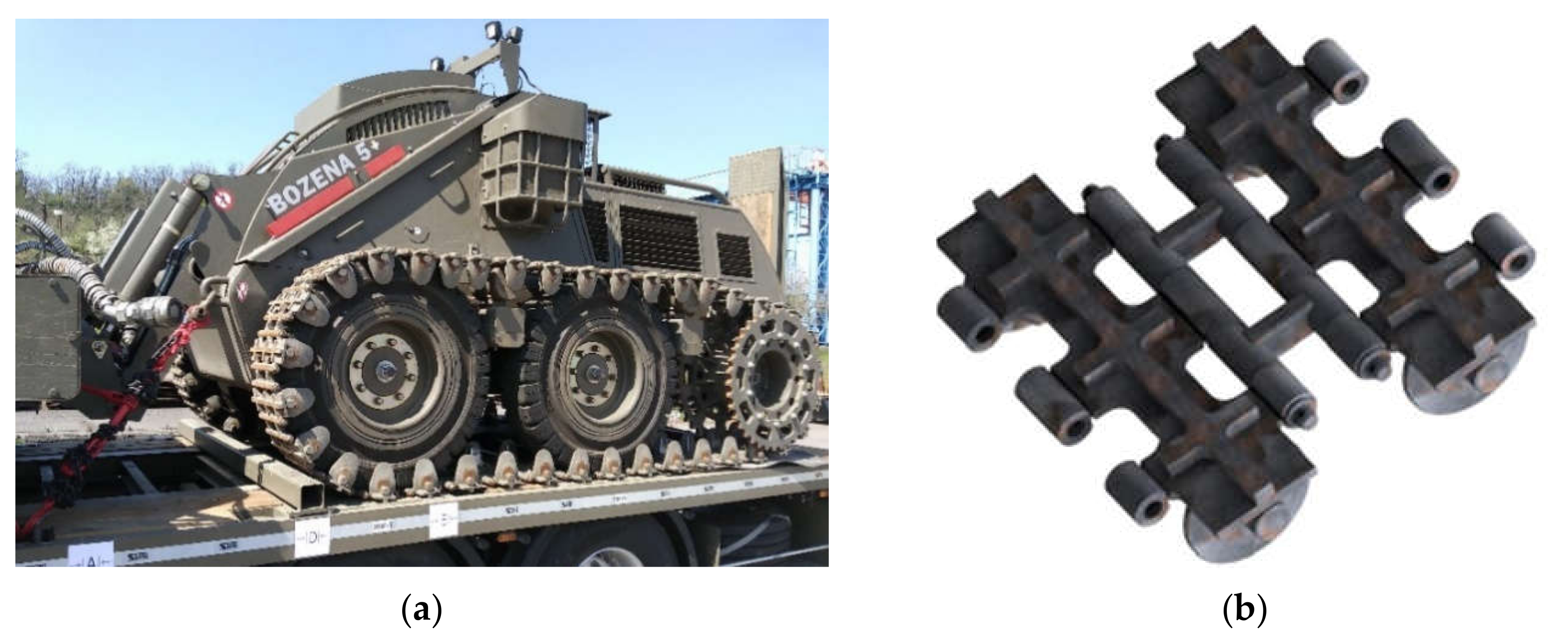
Regarding the facts described above, the authors of this paper wish to point out the possibilities of solving these problems by looking for optimal material for the production of the track, which would ensure reliable operation of the demining machine (Figure 1a). The track is exposed to a significant load from the point of view of the tribological processes during its operation. It is necessary to emphasize that the research underlying the design of a final product of the demining machine Božena 5 was motivated by the authors’ efforts to contribute to protect people in war-torn countries.
By performing the load analysis, we can see (Figure 1b) that the rear part of the solved demining machine Božena 5 is, in certain operational conditions, extraordinarily loaded, which leads to its damage. Sand gets on the contact surfaces and causes an abrasive effect, which leads to damage during the working activity of the tracked chassis. There is gradual wear and loss of the required machine qualities in terms of its lifespan. In the case of a combination of wet sand with mud and high contact pressure, a combination of adhesive and abrasive wear occurs, which finally leads to weakening and a rupture of the track.
Therefore, the choice of proper material took several factors into account including the manufacturing technology (e.g., heat treatment, welding, etc.) and last but not least, the profitability (i.e., the price) has to be taken into consideration [21].
Welding can be understood as one of the methods of the fast and efficient renovation of damaged parts of machines, which is often used in practice. However, it has one major disadvantage, namely, that certain areas of the base material are exposed to a fast thermal as well as a tensile stress-strain cycle. These factors usually degrade the original mechanical properties. Therefore, in terms of the evaluation of the resulting quality of welding joints, it is necessary that a welding joint would have at least approximately the same mechanical properties as a base material. For this purpose, this article presents the results of the experimental measurements of welding joints, which have been realized by means of several welding methods.
The coating process is used in practice to increase the wear resistance of the steel material. Results of some research have shown, that in this manner, it is possible to improve the wear resistance of high-strength steels. The surface of high-strength steel can be treated by electric-arc surfacing electrical-explosion surfacing or electron-beam [22,23]. However, the presented research was to show whether it is possible to achieve increased wear resistance of the high-strength steel material in the weld area without the use of additional treatment processes.
The elementary condition, which must be fulfilled for a selection of vehicle material, is to withstand both static as well as dynamic loads (e.g., from the cockpit of the transportation vehicle or working tool in the case of the handling equipment) [24]. It is necessary to take into account driving on heavy off-road conditions, even, if an unsprung chassis is proposed. All steels, which are currently used (about 2500 types), are defined by their specific properties. These are the result of processing (the technologies) the input raw materials (chemical composition) during manufacturing the material. In this way, we specifically influenced the mechanical properties. The knowledge of the mechanical properties of the used materials reduces the risk of developing a limiting condition. In general, it increases the safety and improves the economy of the structures. The authors wanted to reach this through proper materials and methods.
2. Materials and Methods
The presented research can be considered application research aimed at the use of their results in practice. The application research can be developed only if the basic research has a sufficient progress. There was a problem: the area of the high-strength steels is generally worked out well, however, there is a gap for optimizing the lifespan of the welded high-strength structures [25,26,27,28,29]. Safety is the primary condition for every structure. A resource-based economic approach is proving to be a suitable method for the research. Every designed component must be thoroughly analyzed and also relates to the demining system Božena 5. Therefore, it is necessary to submit an analysis of the current state of the machine. In this way, we recognize all relations (loads, working environment, and processing technologies) that will help find a comprehensive approach to solving an existing problem.
The vehicle manufacturer—Way Industries, a.s.—asked the university to cooperate in optimizing the current solution. The authors checked the real vehicle (Figure 1a) and concluded that change and optimization would be necessary from two points of view.
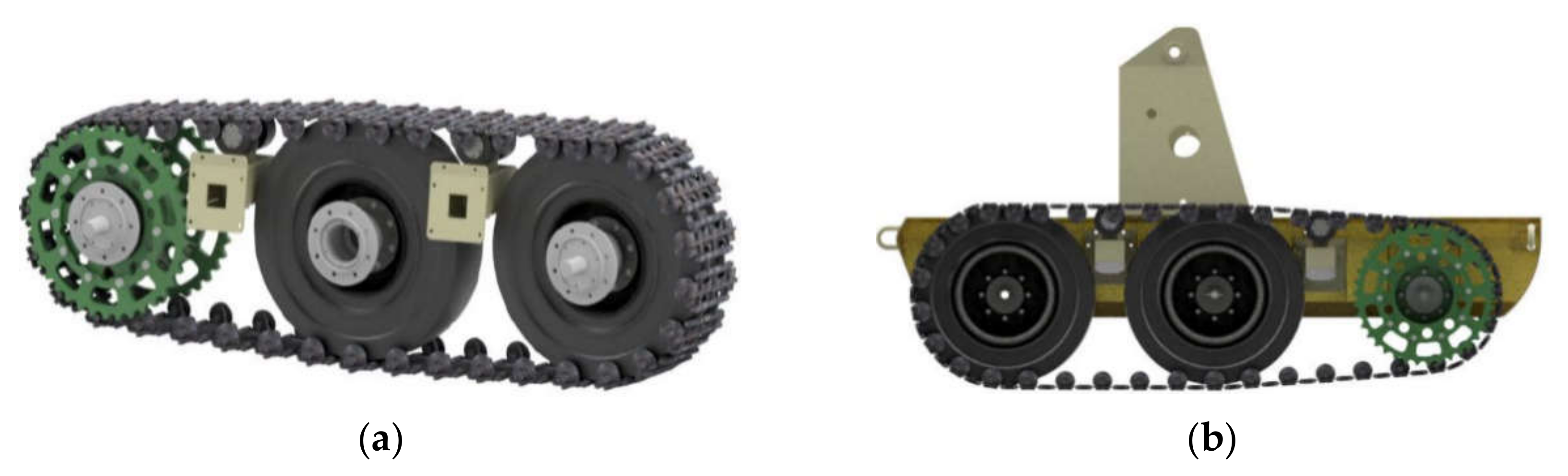
The aspect is the requirement of the company in the production of the demining system Božena 5 with a track chassis without any changes to the wheel chassis. The second aspect is the opinion of the authors [30], which is an implementation of a flexible element to the track chassis (Figure 2).
The original chassis has two idler pulleys for tensioning and their mutual distance is changed by a screw mechanism. However, the entire mechanism does not include any flexible component element between a wheel and the track. The authors think that this element will significantly eliminate the increase in the axial force in the track. Moreover, the track design offers a possibility of optimization. This is caused by the fact that the gear does not fit in the track axis and leads to the generation of additional bending and torsional loads. In this way, we have identified all possible ways and combinations of the track loads (e.g., the tribological stress mentioned in the introduction, fatigue stress, technological interventions (welding), overloading, corrosive environment, incorrect handling, etc.). In the following text, the author deal with wear.
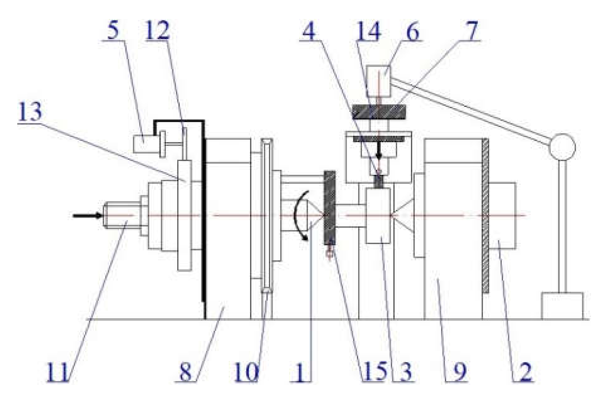
Nowadays, there are several methodologies of experimental wear assessment [4,31,32,33,34]. The mechanical properties of the materials are closely related with the working environment. Components are exposed to the impacts of the environment and the design material also has to be chosen according to this criterion; this reduces the impacts of the wear on the component. The tribological process also develops during mutual movements of bodies and is characteristic of the material interactions of friction units, a substance between them and the environment [35]. The processes run in real time and space. The authors believe that an optimal track design will be created successfully only if information about the material will have sufficient quantity and quality. To investigate the tribological properties of the tested material (one of the ways to load the track), the authors designed a simple testing device, which is shown in Figure 3.
The TriboTester allows for experimental investigation of the adhesive wear of the tested material in combination with an abrasive material.
The essence of the test consists of pressing the testing specimen (the assessed material) against the friction mating part. The electrometer revolutions ensure the movement between these two bodies. The wear of the material is measured by the measuring segment and measuring card connected with computer software (LabWIEW), the results are then recorded and saved in a database. Then, it is possible to create time dependencies of the wear by means of this database.
The software works with the sample frequency of 300 Hz. The arithmetic mean of the measured data is saved to a text file every second. Development of the scanned values can be monitored on the screen in the form of dependence on the wear time.
Parameters of all wear tests are listed in Table 1. Both testing series have been proposed with the same load generated by the mass of m = 2 kg. This load is distributed on a surface S, which is determined by means of Equation (1):
where S is a contact are size; D is a testing roller diameter; b is an edge length of the square testing specimen; and α° is an apex angle of an abrasive roller geometry and a specimen in degrees.
The value of α° = 9.177° is valid for an apex angle for the given geometry of an abrasive roller and a testing specimen. When we take into account other known quantities, the contact area size is S = 16.0171 mm2. The value of pressure p generated between the contacting surfaces of a testing specimen with a cross-section b × b = 4 × 4 mm2 will be in compliance with relation (2):
Hence, the value of the specific pressure was p = 1.225 MPa. The test series No. 1 served for accelerated comparison of the wear results of the used welding methods. A testing time was chosen of 15 h (54,000 s). The authors chose the value of the mutual speed of surfaces being in contact regarding the low operational speed of the deeming machine during operation. Revolutions of the abrasive roller were chosen of n = 3.0 s−1. If we consider the testing roller diameter of D = 50 mm, a resulting peripheral speed was v = 0.4713 m·s−1.
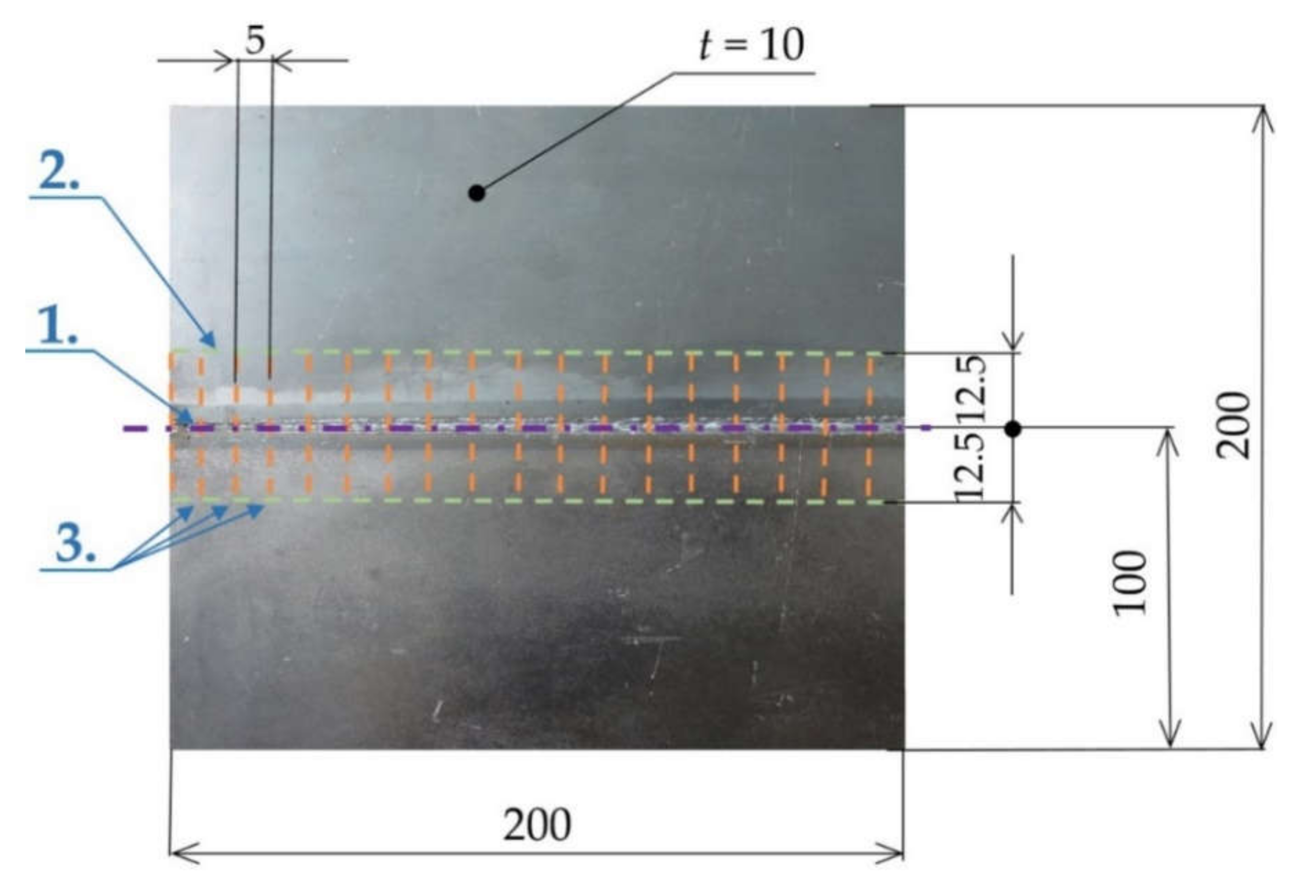
The technological process of the specimens’ preparation for tribological tests was as follows (Figure 4):
- The specimens were created from a weldment. The weldment included two steel plates of the same dimensions of 200 mm × 100 mm × 10 mm. In total, three weldments were produced (i.e., with a laser welding joint, with an electron welding joint, and with a MAG welding joint). This means that the resulting weldment dimensions were 200 mm × 200 mm × 10 mm (Figure 4, step 1).
- In the next step, the weldment (the tested material S960 QL, the plate size—200 mm × 200 mm × 10 mm) was cut by a BOMAR 1300 band (BOMAR Ltd., Brno, Czech Republic) saw in the longitudinal welding joint axis, and subsequently, it was cut to the width of 12.5 mm (Figure 4, step 2). Hence, the dimensions of two semi-products were 200 mm × 10 mm × 12.5 mm. Through the subsequent chip machining on the mill FU-4, both sides of the welding joint were machined, which led to the dimensions of 200 mm × 6 mm × 12.5 mm and roughness of Ra = 3.2.
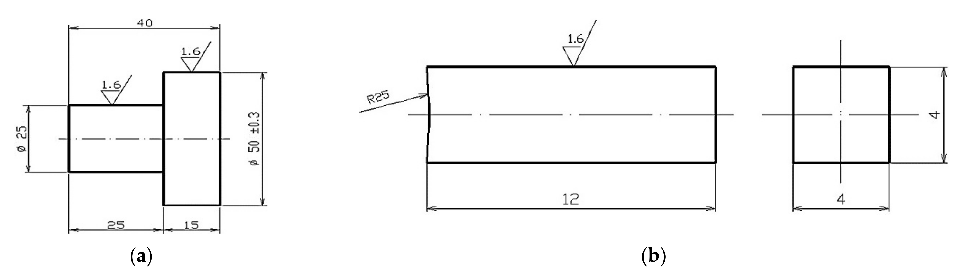
- Another step included cutting of these two semi-products by the BOMAR 1300 band saw to individual specimens for tribological tests with dimensions of 5 mm × 6 mm × 12.5 mm (Figure 4, step 3). Afterward, the specimens were ground on a surface grinding machine BRH 21 (ZVL, Považská Bystrica, Slovakia) to the dimensions of 4 mm × 4 mm × 12 mm with a tolerance of ± 0.04 mm and surface roughness of Ra = 1.6. Before the tribological tests themselves, the contact surfaces of specimens with a radius of R = 25 mm (Figure 5a) were created directly on the TriboTester (University of Žilina, Žilina, Slovakia) by means of sandpaper to the roughness of Ra = 1.6. Before each measurement, the friction surface was cleaned with industrial alcohol. The specimen was dried and then clamped into the testing device (Figure 6).
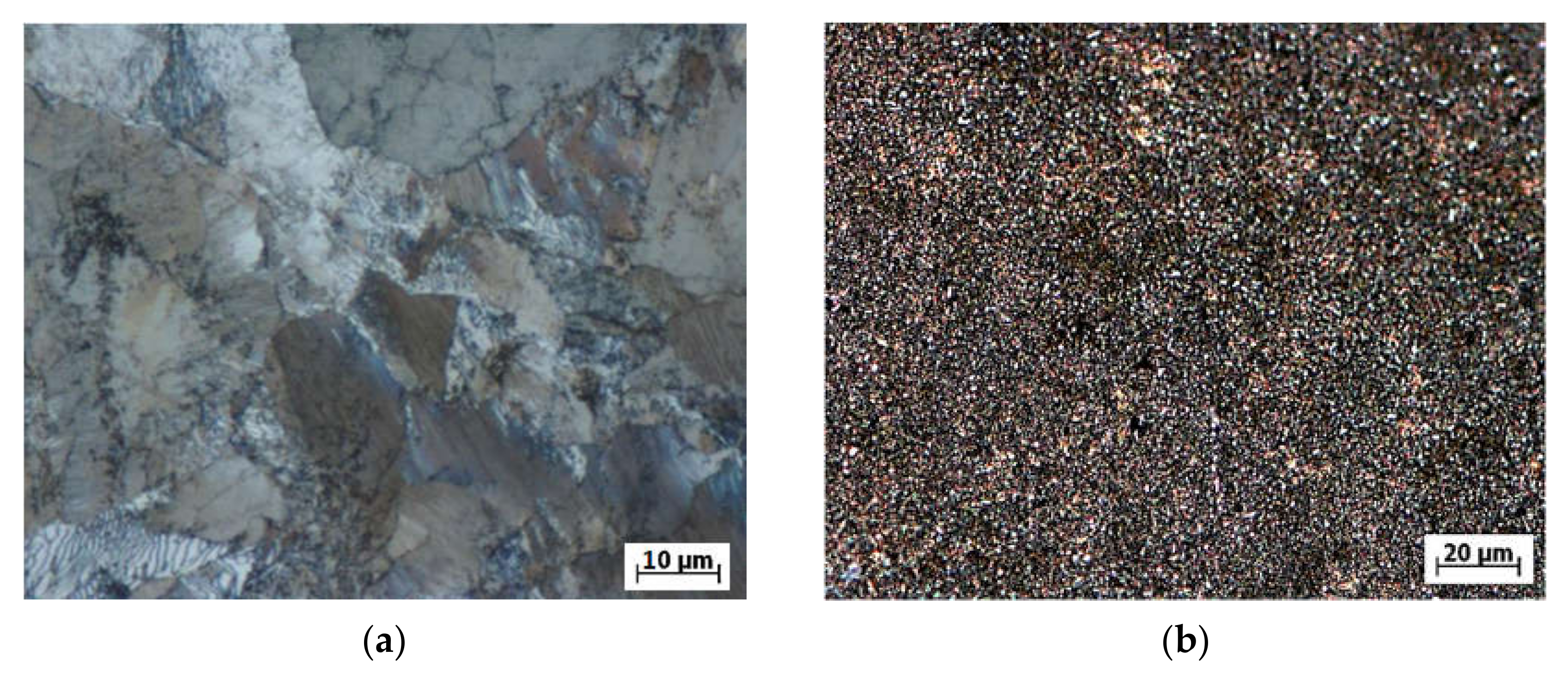
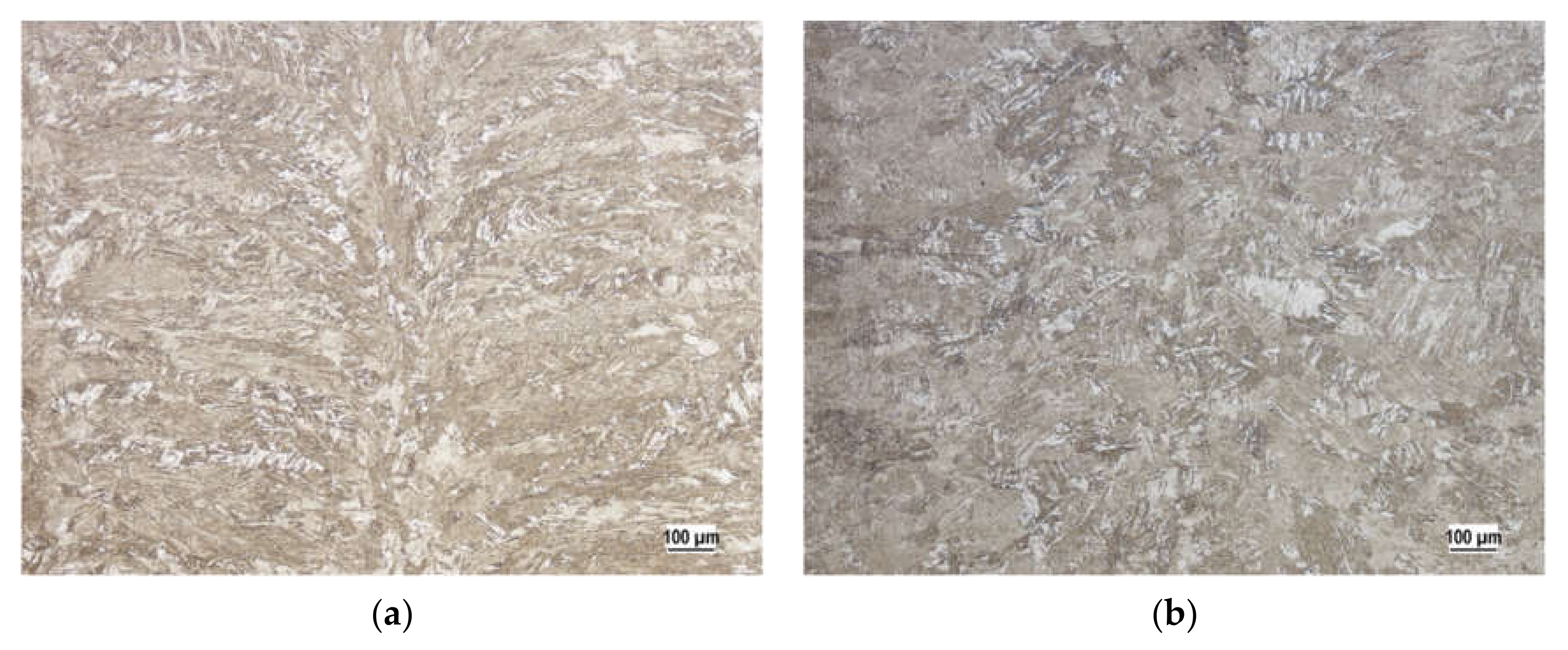
As the contacting body, a grinding roller made of 100CrMnSi6-4 steel was used during the wear process of the tested material. The geometry of the grinding roller is shown in Figure 5a and some parameters of the testing specimen are shown in Figure 5b. The roller was heat treated before the test (because of higher hardness in comparison with the tested material). The state of the grinding roller microstructure before and after heat treatment is shown in Figure 6a,b, respectively. The heat treatment process included hardening (for 40 min in oil of 840 °C), then was tempered at 160 °C for 120 min, and then air cooled. The reached hardness of the roller was 56 HRC on average.
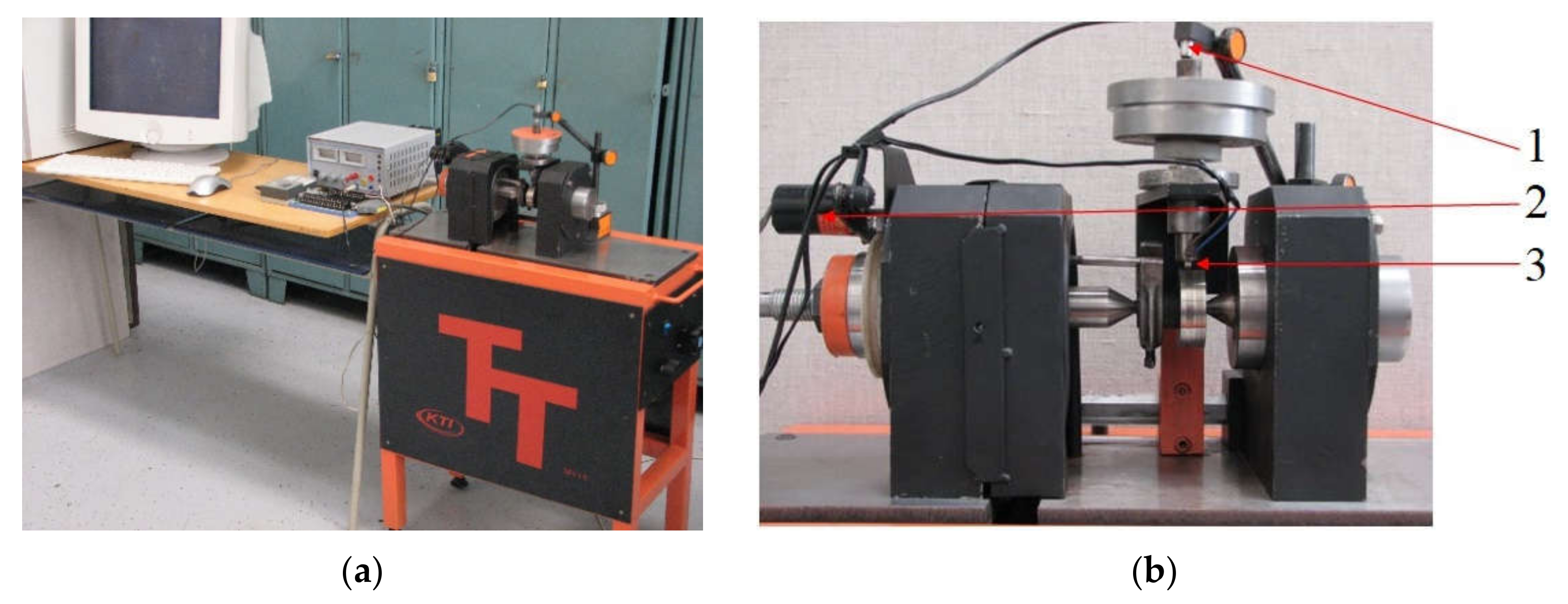
The microstructure of the input grinding roller (Figure 6a) depicted a pearlitic matrix with a small amount of secondary cementite, which was segregated along the boundaries of austenitic grains. Average measured hardness of the 100CrMnSi6-4 steel is listed in Table 2. Table 3 includes the chemical composition of the tested material S960Ql. A layout of the used TriboTester in laboratory is shown in Figure 7.
We observed the microstructure of the base material Strenx 960 (SSAB, Stockholm, Sweden) and also the change of the structure after welding by individual technologies, namely laser beam, the electron beam, and the MAG technology (metal active gas) to achieve a more detailed overview of the investigated material.
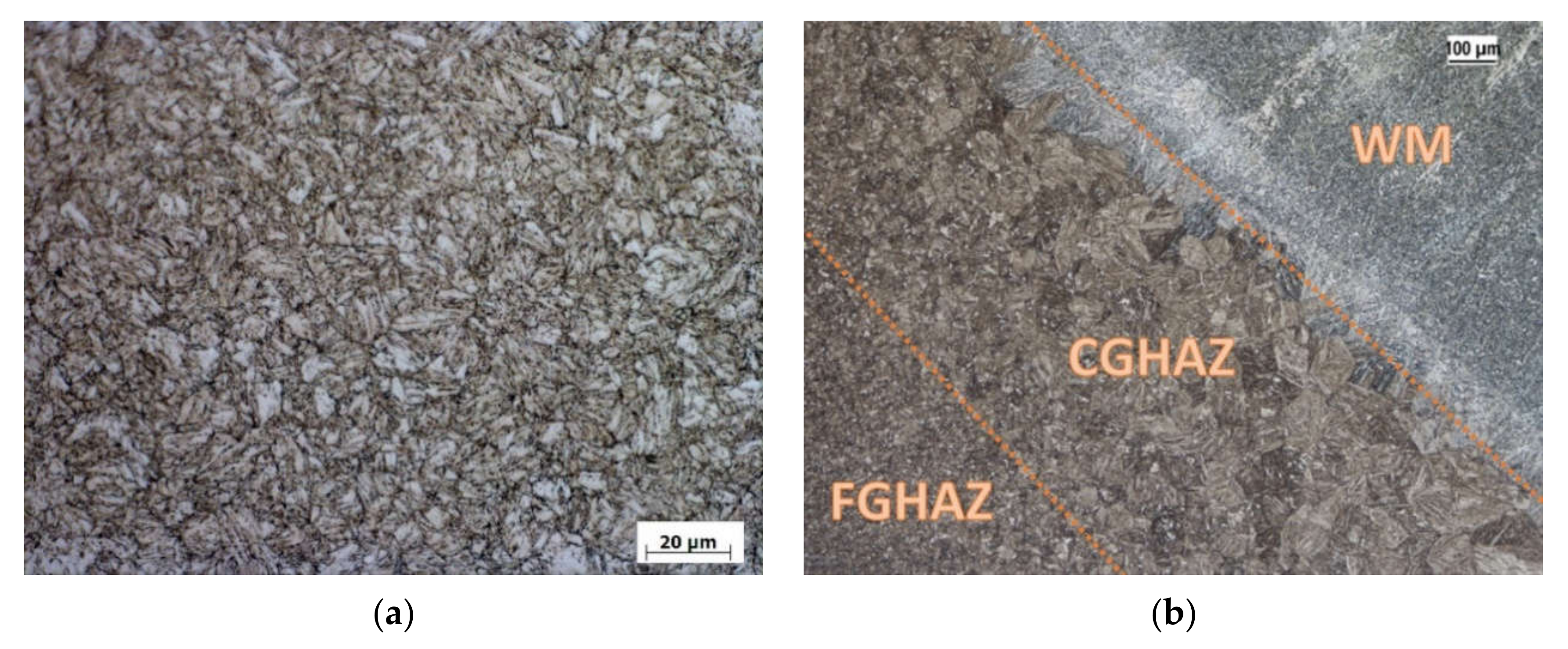
Figure 8a depicts the microstructure of the high-strength steel Strenx 960. It has a fine-grain structure formed by low-carbon tempered martensite. Figure 8b depicts the microstructure of the material Strenx 960 welded by MAG technology in the location of the transition of weld metal to the HAZ. In this figure, it is possible to recognize three zones:
- WM—weld metal;
- CGHAZ—coarse grain heat affected zone, which is the HAZ with a coarse grain structure, heated to a temperature 1100 °C ≤ Tmax ≤ Tm, where Tm is the steel melting point; and
- FGHAZ—fine grain heat affected zone, which is the HAZ with a fine grain structure, heated to temperature above A3 (i.e., 900 °C ≤ Tmax ≤ 1100 °C).
For all three assessed types of welding processes (MAG, electron, laser), the weld microstructure consisted of three main parts: the base material, the heat affected area (HAZ), and weld (filler) metal. Such a typical form of the weld area was also achieved by [36,37,38,39] during their investigation of the weld area of the construction steel by MAG or in [40,41] laser welding. The microstructure of the base material was in all cases created by the tempered martensite. Li at al. [41] also observed locations of martensite structure in the weld during the laser welding of S960QL steel. Figure 9a shows the microstructure of the weld metal of the material Stenx 960 welded by the electron beam and Figure 9b shows the microstructure of the welding metal welded by the laser beam.
Here, we can observe the direction of cooling of the weld metal and creating the columnar crystals in the direction of a temperature gradient. The cooling rate after welding directly relates to the welding speed. In this case, we reached the following speeds: 11 mm·s−1 for the electron beam, 7.5 mm∙s−1 for laser welding, and 5 mm∙s−1 for MAG welding. The thermal input to the material in this case reached the following values: 0.55 kJ∙mm−1 for the electron beam, 0.63 kJ∙mm−1 for laser welding, and 1.67 kJ∙mm−1 for MAG welding. The material thickness was 10 mm for all technologies and the ambient temperature was 20 °C.
The welding of plates was performed by the First Welding Company, Inc. (Bratislava, Slovakia). For the laser welding process, the solid-state fiber laser, type YLS 5000-S1, was used. Parameters of the laser welding conditions are listed in Table 4. The welding process of high-productive methods (i.e., plasma method) were realized by the automated way using a welding robot and welding source OTC Daihen (Daihen Inc., Tipp City, OH, USA). Parameters of electron welding are introduced in Table 5. Finally, the experimental plates were welded by MAG welding technology by means of a common welding automat. The welding automat ensures a constant welding speed in comparison with manual welding. Moreover, electronics control all parameters of the welding process. Therefore, the welding joint quality is much higher. Parameters of the MAG welding technology are presented in Table 6. The authors decided for the laser and electron welding technologies based on their research in [42]. The research has proven the weak influence of the mechanical properties compared with the base material. For documentary purposes, the authors introduced the average results of the research of mechanical properties according to [42] in Table 7.
Then, the authors performed the measurements of tribological properties by means of the introduced unique test device. Based on the obtained results, optimal production technology for the solved tracked machine Božena 5 were chosen.
3. Results
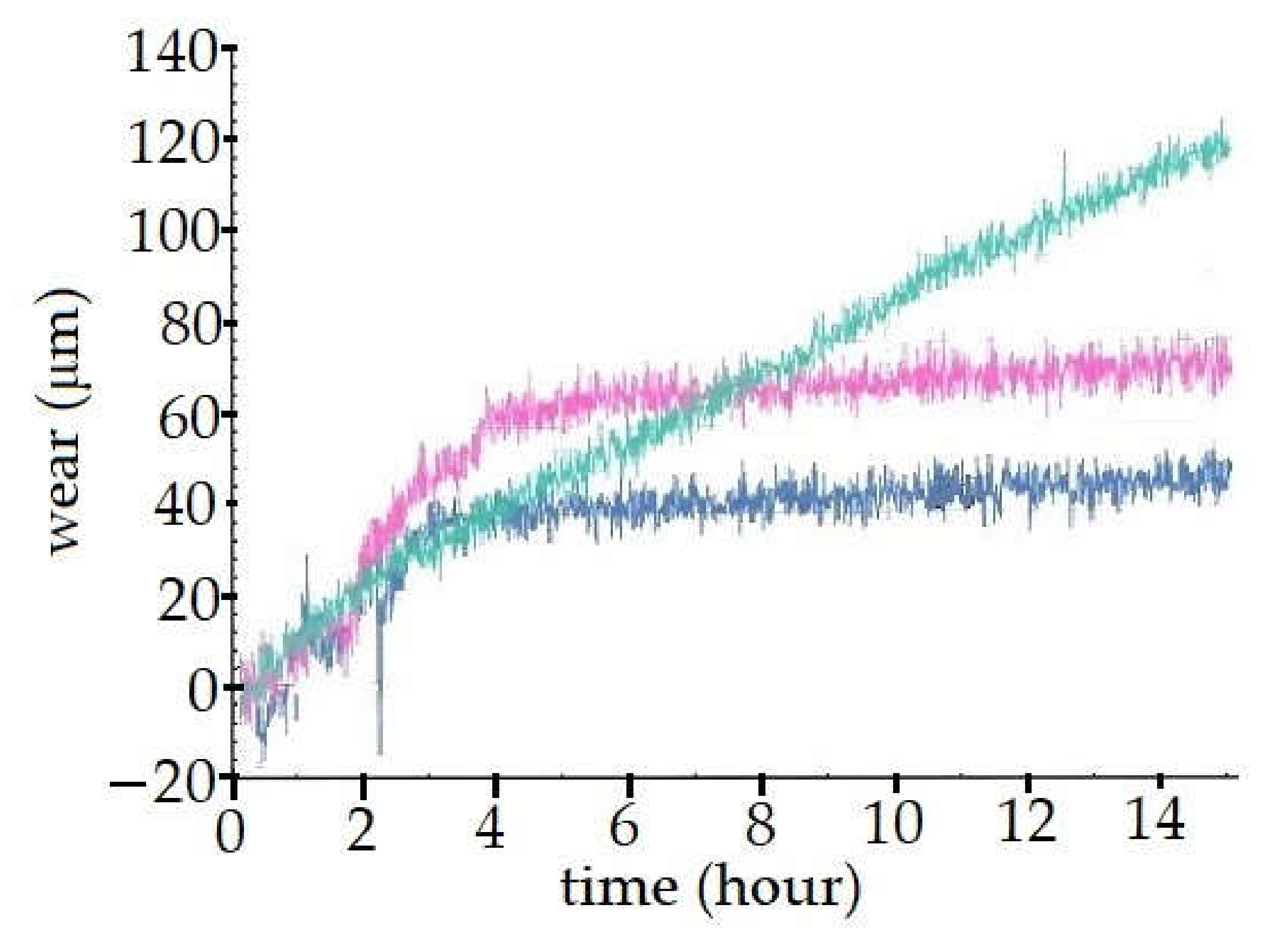
Specimens were attached to the test device. The measuring process began without the measurement data. This step was necessary to fit the components by forming a rounding with a radius of 25 mm on the surface of the specimen according to the shape of the abrasive roller (Figure 5). The number of repetitions of all tests was seven. A diagram of the first comparative measurement is shown in Figure 10 (the green curve). It depicts the average wear values of seven performed measurements of weld metal made by the MAG technology. The wear rate of the specimen (for chosen parameters) at the beginning of the test was 12 µm∙h−1. During the test, the wear rate decreased only slightly (i.e., to the value of 8.5 µm∙h−1). The test time was 15 h. The detected total wear was 133 µm.
As another test, measurement of the wear of the weld material of specimen No. 2 welded by the laser method was performed. A diagram shown in Figure 10 (the red curve) depicts the time dependence of the wear of seven performed measurements for the weld metal of the S960QL steel welded by the laser beam. The test conditions were the same as in the previous test case. It is interesting that the wear behavior was significantly different in comparison with the previous measurement. At the beginning, the wear rate of the specimen was 18 µm∙h−1. After four to six hours of the test, the wear rate significantly decreased (i.e., to the value of 2 µm∙h−1). The total test time was again 15 h. The observed increased wear rate during the run-in was caused by the pushing of harder martensite elements to the softer matrix of the sub-critical HAZ. The wear rate was significantly decreased after saturation of this process. This fact is demonstrated by a right part of the graph in Figure 10. The total found wear had the value of 78 µm (i.e., the results showed lower wear of 41%) at the defined condition in comparison with specimens welded by the MAG technology. This is an essential finding for the implementation of the welded material S960QL for the track of the demining machine Božena 5.
As a final test in the search of optimal welding technology in terms of tribological wear, the specimen welded by the electron beam was tested. The wear time dependence of this test specimen is shown in Figure 10 (the blue curve). Results of the tests [41] indicated higher toughness of the surface layer in comparison with the MAG as well as with the laser welding technology. It had a significant effect on the investigated tribological lifetime. When the results of welding by the laser and electron beam technology were compared (Figure 10, the red and blue curves), their wear rates were very similar, however, the wear rate was smaller for the electron weld. This was caused by the different morphologies of the structure, which is reached by individual welding methods.
At the beginning of the test, the wear rate of the specimen welded by the electron beam was 12 µm∙h−1. The same values were also reached by specimens welded by the MAG technology. After three hours, the wear rate decreased significantly (i.e., to the value of 2 µm∙h−1). It is interesting that this value was the same for both the laser beam and the electron beam. At time t = 4 h since the test started, both curves (electron and laser) began to show parallelism and thus, the same increase in the wear rate for each additional unit of time. The test time was again 15 h. The maximal average value of wear for the laser beam was 44 µm. In comparison with the specimen welded by the MAG technology, it showed a reduction of wear of up to 70%. The authors assumed that to reach similar results for the MAG technology, the heat treatment of the track would have to follow. This technology would influence the final price of the product.
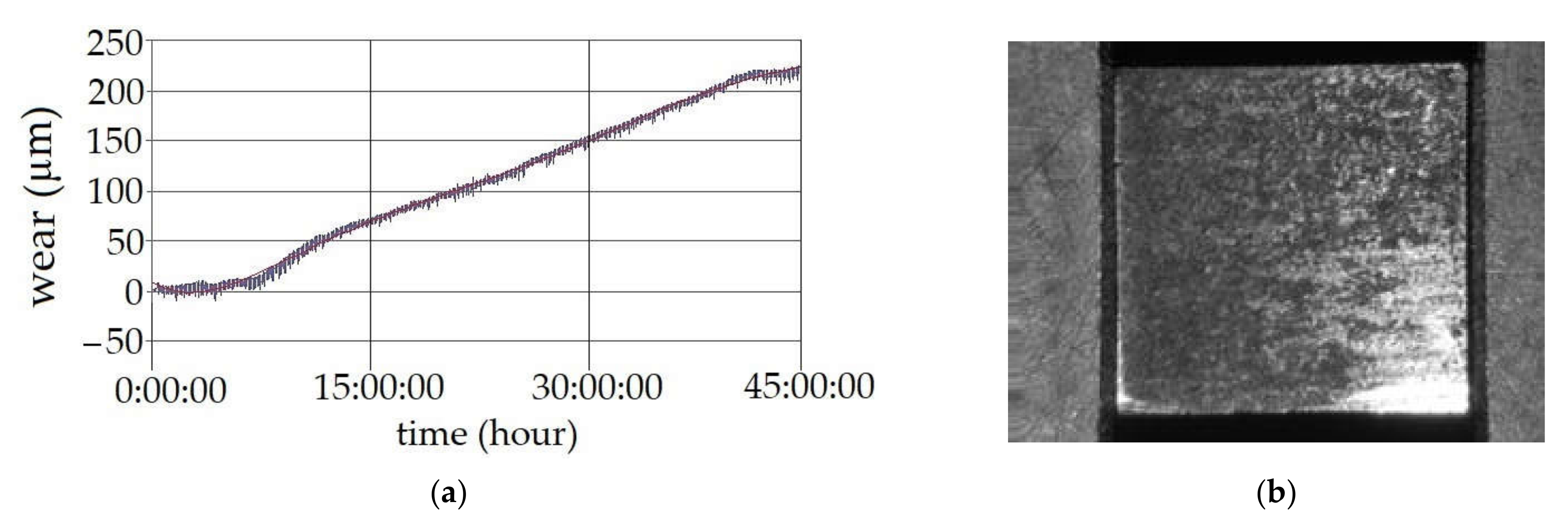
Finally, the authors also measured the tribological properties of the base material. This time, the authors decided on a test duration of 45 h. Other parameters remained the same as in the previous tests. A graph in Figure 11a represents the dependence of the wear size of the testing specimen of the welded material S960 QL by MAG technology. The macrostructure of the friction surface of the testing specimen after the tribological test is depicted in Figure 12b. At the beginning of the test, an almost negligible learning curve was visible. After the test conditions settled, the component started to wear uniformly. The main contribution of the investigation was the comparison with the previous tests of wear after 15 h. Specimens of the base materials have shown an average wear rate of 78 µm. At the given test conditions, the MAG welding technology represented a 41% worsening of tribological wear in comparison with the base material. The laser beam welding technology seems to be neutral in this comparison. The electron beam showed a significant improvement. After 45 h of the test, the observer wear rete was 237 µm. It is approximately three-times higher value of wear reached in 15 h (i.e., just in a third of the test time).
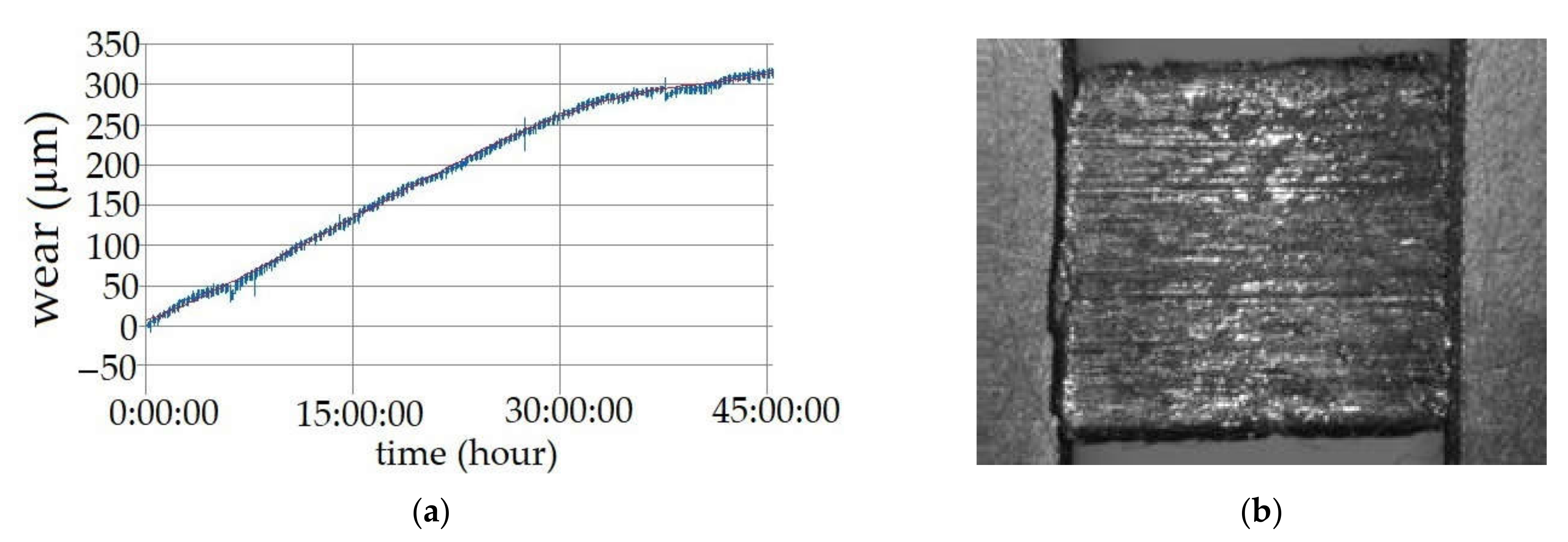
This fact and the graph course indicate an even wear of the structure. Figure 12a shows the macrostructure of the friction surface of one of the tested specimens of the base material. The friction surface was in a good state, and the abrasive effect of the released particles of the material was not seen in this case. Figure 12b depicts the macrostructure of the friction surface of the testing specimen after the tribological test of the welded material S960QL by MAG technology. As the current track technical solution uses MAG technology, the authors performed an investigation of the wear of this weld through another test lasting 45 h.
4. Discussion
Comparing Figure 10 (the green curve) and Figure 11a, it is possible to identify practically the same trend of the material wear process (it is logical, because it is the same material and the same test). After 15 h, both tests showed the same values of wear (130 μm to 140 μm on average). The maximal observed wear of the specimen welded by the MAG technology was 320 μm after 45 h.
Then, the authors realized a comparison of the results for the base and the welded material (Figure 11a and Figure 12a). The graph in Figure 11a) shows that the wear rate of the testing specimen was 9 μm·h−1. The wear rate decreased to 5 μm·h−1 during the test. This fact can be explained by the mechanism of strengthening the welded material during the test. Comparing the graphs in Figure 11a and Figure 12a, we can see that wear on the welded specimen was greater. This was caused due to reduced toughness. These mechanical properties were investigated in [42]. The beginning of the toughness reduction of the welding joint with increasing heat output is caused by the thermomechanical effect of the welding process in the HAZ (heat-affected zone) of the welding joint. It is obvious, that at higher heat outputs, the cooling rate will be lower, however, the heat generated during the welding process will affect a larger area, which will be shown by a much more pronounced deformation and expansion effect in induced heating and cooling of the welded material [39]. Therefore, the solidified material has better adhesive and abrasive properties. The decrease in toughness will be accompanied by increased hardness of the material after welding. This fact has led the authors to an opinion that it is necessary to measure the material hardness.
Figure 11b shows the macrostructure of the abrasive surface of the testing specimen after the test. It can be seen that there was a difference in the friction surfaces (Figure 11b and Figure 12b). During the cyclic mutual movement, the tested material is damaged. After further mutual movements, a disruption occurs and the material is torn out from the component surfaces. This material has no immediate opportunity to leave the space between the materials. This is a typical case of the wear mechanism also described in [43], which investigated the wear of the anti-corrosion steel as well as in [32], who investigated the properties of the bearing steel. Anyway, it remains between the surfaces for a certain time. In this way, it remains on the components’ surfaces—this is the essence of physical wear. The specimen without welding seems to be more suitable in terms of the measured wear values. We observed a lower rate of crumbling of the surface particles as well as lower wear due to this fact. According to the presented research, the effect of the MAG welding technology increased the abrasive wear by 30%. The non-welded material had better homogeneity. Our goal was to confirm that tribological wear of the track will not be the reason of its disruption in practice. This especially relates its welding joints.
Results of the experiments recommend the application of progressive welding technologies for machine components, which are exposed to adhesive and abrasive wear. The results also lead to findings that progressive welding technologies (e.g., the electron beam and the laser beam) can partially substitute heat treatment technologies in order to reach equivalent results. Ultimately, heat treatment of welded structures has dual goals in practice. On one hand, we tried to eliminate or reduce the internal stress in the welded structure and, on the other hand, we need to remove unwanted heterogeneous mechanical, physical, or chemical properties in welding joints by heat treatment.
5. Conclusions
In the presented research, the selected tribological properties of the tested material in combination with adhesive and abrasion processes were investigated. The article has:
- Presented within possibilities (confidential military material) technical and material solutions of the machine for special purposes;
- Briefly described the design and built the test device, which was equipped with the needed measuring technics; and
- Presented a microstructure of the various welding technologies of the welding joints of high-strength steel S960 QL.
It was investigated:
- The base material had better adhesive and abrasive lifespan compared to the welding joints created by the MAG conventional welding technology as well as by the unconventional laser beam welding technology and the electron beam welding technology;
- Presented within possibilities (confidential military material) technical and material solution of the machine for special purposes;
- Wear of the base material during 45-h tests was on average by 30% lower (in comparison with the current MAG solution).
Based on the obtained results, it may be proposed to use progressive welding technologies to improve the lifespan of the machine track. It can also be argued that in certain cases, it is possible to substitute heat treatment of conventional welding joints by progressive welding technologies themselves.
Author Contributions
Conceptualization, M.B., P.K., and M.S.; methodology, M.B., P.K., and M.S.; software, M.B. and J.D.; validation, M.B., J.D., and P.K.; investigation, M.B., P.K., and M.S.; writing—original draft preparation, M.B. and J.D.; writing—review and editing, J.D., M.S., and P.K.; supervision, M.S. All authors have read and agreed to the published version of the manuscript.
Funding
Acknowledgment belongs to the Ministry of Education, Science, Sport, and Sport in the Slovak Republic in connection with the implementation of the Research of intelligent systems and processes with Industry 4.0 focusing on joining materials associated with high energy sources—laser and electron beam, contract number 1227/2018.
Institutional Review Board Statement
Not applicable.
Informed Consent Statement
Not applicable.
Data Availability Statement
Not applicable.
Conflicts of Interest
The authors declare no conflict of interest.
References
- Tobola, D. Impact of Mechanical Processes as a Pre-Sulphonitriding Treatment on Tribology Properties of Selected P/MTool Steels. Materials 2019, 12, 3431. [Google Scholar] [CrossRef] [Green Version]
- Sadhasivam, M.; Mohan, N.; Sankaranarazanan, S.R.; Kumaresh Babu, S.P. Investigation on mechanical and tribological behaviour of titanium diboride reinforced martensitic stainless steel. Mater. Res. Express 2020, 7, 1–13. [Google Scholar] [CrossRef]
- Lisiecki, A. Tribilogy and Surface Engineering. Coatings 2019, 9, 663. [Google Scholar] [CrossRef] [Green Version]
- Akinci, A. Influence of load and speed on sliding tribology of silica-polyamide composites against AlSi 4140 steel. Acta Phys. Pol. A 2014, 125, 478–480. [Google Scholar] [CrossRef]
- Dekys, V.; Stalmach, O.; Soukup, J.; Sapietova, A.; Rychlikova, L. Detection of composite damage by IR NDT using ultrasonic and optic excitation. Matec Web Conf. 2019, 254, 1–7. [Google Scholar] [CrossRef]
- Žmindák, M.; Kaco, M.; Novák, P.; Radziszewski, L.; Soukup, J. Determination of the laminate strains using discrete damage mechanics. Matec Web Conf. 2019, 254, 1–12. [Google Scholar] [CrossRef]
- Kopecky, M.; Cuth, V.; Letko, I.; Vavro, J. Testing equipment for fatigue and damage tests of steel cords. In Proceedings of the 2nd International Conference on Structural and Construction Engineering, Rome, Italy, 23–26 September 2003. [Google Scholar]
- Sławiński, G.; Malesa, P.; Świerczewski, M. Analysis Regarding the Risk of Injuries of Soldiers Inside a Vehicle during Accidents Caused by Improvised Explosive Devices. Appl. Sci. 2019, 9, 4077. [Google Scholar] [CrossRef] [Green Version]
- Bernetič, J.; Vuherer, T.; Marčetič, M.; Vuruna, M. Experimental research on new grade of steel protective material for light armored vehicles. Stroj. Vestn. J. Mech. Eng. 2012, 6, 416–421. [Google Scholar] [CrossRef] [Green Version]
- Rahoui, S.; Turq, V.; Bonino, J.P. Effect of thermal treatment on mechanical and tribological properties of hybrid coatings deposited by sol-gel route on stainless steel. Surf. Coat. Technol. 2013, 235, 15–23. [Google Scholar] [CrossRef] [Green Version]
- Degan, G.A.; Coltrinari, G.; Lipiello, D.; Pinyari, M. Effects of ground conditions on whole-body vibration exposure on cars: A case study of drivers of armored vehicles. Wit Trans. Built Environ. 2017, 176, 431–438. [Google Scholar] [CrossRef] [Green Version]
- Leitner, B.; Decký, M.; Kováč, M. Road pavement longitudinal evenness quantification as stationary stochastic process. Transport 2019, 34, 195–203. [Google Scholar] [CrossRef] [Green Version]
- Chudzikiewitz, A.; Stelmach, A.; Wawryznski, W.; Firlik, B.; Czechyra, B. Vibro-acoustic evaluation of a light rail vehicle. In Proceedings of the International Congress on Sound and Vibration, Athens, Greece, 10–14 July 2016; pp. 1–8, ISBN 978-1-5108-2716-5. [Google Scholar]
- Leitner, B.; Figulli, L. Fatigue life prediction of mechanical structures under stochastic loading. Matec Web Conf. 2018, 157, 1–11. [Google Scholar] [CrossRef] [Green Version]
- Wezssenhoff, A.; Opala, M.; Koziak, S.; Melnik, R. Characteristics and investigation of selected manufacturing defects of passenger car tires. Transp. Res. Procedia 2019, 40, 119–126. [Google Scholar] [CrossRef]
- Chao, Z.; Mao, F.; Liu, X.; Li, H.; Han, S. Research on influence factor about the dynamic characteristic of armored vehicle hydraulic-driven fan system. AIP Conf. Proc. 2017, 1794, 1–8. [Google Scholar] [CrossRef] [Green Version]
- Gerlici, J.; Sakhno, V.; Yefymenko, A.; Verbitskii, V.; Kravchenko, A.; Kravchenko, K. The stability analysis of two-wheeled vehicle model. In Proceedings of the 22nd Slovak-Polish Scientific Conference on Machine Modelling and Simulations, Sklene Teplice, Slovakia, 5–8 September 2017. [Google Scholar]
- Novak, L.; Cornak, S.; Droppa, P. Selected Issue of an Evaluation of Passive Armor. In Proceedings of the 20th International Scientific Conference Transport Means, Palanga, Lithuania, 5–7 October 2016; pp. 127–132, ISBN 2351-7034. [Google Scholar]
- Droppa, P.; Kopecky, I. Possibility of Using Thermo Vision Diagnostics for Special Mobile Technics. In Proceedings of the Transport Means—Proceedings of the International Conference, Kaunas, Lithuania, 23–24 October 2014; pp. 393–396, ISBN 2351-4604. [Google Scholar]
- Erdik, A.; Kilic, S.A.; Kilic, N.; Bedir, S. Numerical simulation of armored vehicles subjected to undercarriage landmine blasts. Shock Waves 2016, 26, 449–464. [Google Scholar] [CrossRef] [Green Version]
- Rohlfs, C.; Sulliva, R. The cost/effectiveness of armored tactical wheeled vehicles for overseas US army operations. Def. Peace Econ. 2013, 24, 293–316. [Google Scholar] [CrossRef] [Green Version]
- Kapralov, E.V.; Rykov, S.V.; Budovskikh, E.A.; Gromov, V.E.; Vashchuk, E.S.; Ivanov, Y.F. Structural-phase states and properties of coatings welded onto steel surfaces using powder wires. Bull. Russ. Acad. Sci. Phys. 2014, 78, 1015–1021. [Google Scholar] [CrossRef]
- Raikov, S.V.; Kapralov, E.V.; Ivanov, Y.F.; Budovskikh, E.A.; Gromov, V.E. Structure gradient in wear-resistant coatings on steel. Steel Transl. 2015, 45, 120–124. [Google Scholar] [CrossRef]
- Gardynski, L.; Caban, J.; Barta, D. Research of composite materials used in the construction of vehicle bodywork. Adv. Sci. Technol. Res. J. 2018, 12, 181–187. [Google Scholar] [CrossRef]
- Mičian, M.; Harmaniak, D.; Nový, F.; Winczek, J.; Moravec, J.; Trško, L. Effect of the t8/5 Cooling Time on the Properties of S960MC Steel in the HAZ of Welded Joints Evaluated by Thermal Physical Simulation. Metals 2020, 10, 229. [Google Scholar] [CrossRef] [Green Version]
- Gáspár, M. Effect of Welding Heat Input on Simulated HAZ Areas in S960QL High Strength Steel. Metals 2019, 9, 1226. [Google Scholar] [CrossRef] [Green Version]
- Kawulok, P.; Schindler, I.; Smetana, B.; Moravec, J.; Mertova, A.; Droydova, L.; Kawulok, R.; Opela, P.; Rusy, S. The Relationship between Nil-Strength Temperature, Zero Strength Temperature and Solidus Temperature of Carbon Steels. Metals 2020, 10, 399. [Google Scholar] [CrossRef] [Green Version]
- Frankovský, P.; Delyová, I.; Sivák, P.; Kurylo, P.; Pivarčiová, E.; Neumann, V. Experimental assessment of time-limited operation and rectification of a bridge crane. Materials 2020, 13, 8. [Google Scholar] [CrossRef]
- Frankovský, P.; Brodnianská, Z.; Bocko, J.; Trebuňová, M.; Kostka, J.; Kicko, M.; Čarák, P. Application of holographic interferometry in the analysis of stress states in a crack root area. Appl. Opt. 2020, 59, D170–D178. [Google Scholar] [CrossRef] [PubMed]
- Blatnický, M.; Dižo, J.; Harušinec, J. Modification of a design of a wheel-tracked chassis of a mine clearing machine. AIP Conf. Proc. 2019, 1–4. [Google Scholar] [CrossRef]
- Uddin, G.M.; Khan, A.A.; Ghufran, M.; Tahir, Z.-U.-R.; Asim, M.; Sagheer, M.; Jawad, M.; Ahmad, J.; Irfan, M.; Waseem, B. Experimental study of tribological and mechanical properties of TiN coating on AISI 52100 bearing steel. Adv. Mech. Eng. 2018, 10, 1–10. [Google Scholar] [CrossRef]
- Acar, N.; Franco, J.M.; Kuhn, E.; Gonçalves, D.E.P.; Seabra, J.H.O. Tribological Investigation on the Friction and Wear Behaviors of Biogenic Lubricating Greases in Steel–Steel Contact. Appl. Sci. 2020, 10, 1477. [Google Scholar] [CrossRef] [Green Version]
- Opaliński, M.; Mazuro, P.; Klasik, A.; Rostek, E. Tribological examination of different steel materials after special heat treatment and salt bath nitriding. Arch. Metall. Mater. 2016, 61, 1881–1888. [Google Scholar] [CrossRef]
- Hernández-Sierra, M.T.; Bravo-Sánchez, M.G.; Báez, J.E.; Aguilera-Camacho, L.D.; García-Miranda, J.S.; Moreno, K.J. Improvement Effect of Green Lubricants on the Tribological and Mechanical Performance of 4140 Steel. Appl. Sci. 2019, 9, 4896. [Google Scholar] [CrossRef] [Green Version]
- Gerlici, J.; Gorbunov, M.; Kravchenko, K.; Prosvirova, O.; Lack, T. Noise and temperature reduction on the contact of tribological elements during braking. In Proceedings of the 22nd Slovak-Polish Scientific Conference on Machine Modelling and Simulations, Sklene Teplice, Slovakia, 5–8 September 2017. [Google Scholar]
- Holmberg, K.; Erdemir, A. Influence of tribology on global energy consumption, costs and emissions. Friction 2017, 5, 263–284. [Google Scholar] [CrossRef]
- Benedetti, M.; Fontanari, V.; Santus, C. Crack growth resistance of MAG butt-welded joints of S355JR construction steel. Eng. Fract. Mech. 2013, 108, 305–315. [Google Scholar] [CrossRef]
- Chiarelli, M.; Lanciotti, A.; Sacchi, M. Fatigue resistance of MAG welded steel elements. Int. J. Fatigue 1999, 21, 1099–1110. [Google Scholar] [CrossRef]
- Vavro, J.; Vavro, J.; Kovacikova, P. Distribution of stress around the graphitic particles in cast iron microstructure. Appl. Mech. Mater. 2014, 486, 20–25. [Google Scholar] [CrossRef]
- Sowards, J.W.; Pfeif, E.A.; Connolly, M.; McColskey, J.D.; Miller, S.L.; Simonds, B.; Fekete, J.R. Low-Cycle fatigue behavior of fiber-laser welded, corrocion-resistant, high-strength low alloy sheet steel. Mater. Des. 2017, 121, 1–13. [Google Scholar] [CrossRef] [Green Version]
- Li, L.; Mi, G.; Wang, C. A comparison between induction pre-heating and induction post-heating of laser-induction hybrid welding on S690QL steel. J. Manuf. Process. 2019, 43, 276–291. [Google Scholar] [CrossRef]
- Sága, M.; Blatnická, M.; Blatnický, M.; Dižo, J.; Gerlici, J. Research of the fatigue life of welded joints of high strength steel S960 QL created using laser and electron beams. Materials 2020, 11, 2539. [Google Scholar] [CrossRef] [PubMed]
- Qin, W.; Kang, J.; Li, J.; Yue, W.; Liu, Y.; She, D.; Mao, Q.; Li, Y. Tribological behavior of the 316L stainless steel with heterogenous lamella structure. Materials 2018, 11, 1839. [Google Scholar] [CrossRef] [PubMed] [Green Version]
Figure 1.
(a) A demining machine Božena 5; (b) a segment of the track.

Figure 2.
(a) A drive-system of the demining machine Božena 5; (b) a side-view of a model.

Figure 3.
A scheme of a testing device TriboTester (developed by the authors): 1—sliding tip of the driving shaft; 2—backstop tip; 3—friction mating part; 4—testing specimen; 5—dynamometric revolution indicator; 6—scanner TESA; 7—pressure balance; 8—driving shaft arrangement; 9—backstop shaft arrangement; 10—drive pulley; 11—spacer bolt of the adjustable tip; 12—speedometer gear; 13—speedometer gear; 14—adjustable device of testing specimen; 15—catch cam.

Figure 4.
A technological process of the testing specimens’ preparation: 1—a welding joint, 2—cutting to the required length, 3—dividing of semi-products to the specimens. Dimensions are in millimeters.
Figure 4.
A technological process of the testing specimens’ preparation: 1—a welding joint, 2—cutting to the required length, 3—dividing of semi-products to the specimens. Dimensions are in millimeters.

Figure 5.
(a) The geometry of the abrasive mating part. (b) The geometry of the testing sample for detecting the tribological properties of the tested material. Dimensions are in millimeters.
Figure 5.
(a) The geometry of the abrasive mating part. (b) The geometry of the testing sample for detecting the tribological properties of the tested material. Dimensions are in millimeters.

Figure 6.
The microstructure of the 100CrMnSi6-4 steel before heat treatment: (a) The microstructure of the abrasive roller from the material 100CrMnSi6-4; (b) the photo taken in the polarized light, etched by Nital 2%.
Figure 6.
The microstructure of the 100CrMnSi6-4 steel before heat treatment: (a) The microstructure of the abrasive roller from the material 100CrMnSi6-4; (b) the photo taken in the polarized light, etched by Nital 2%.

Figure 7.
The experimental workplace for measuring the material wear: (a) A layout in a laboratory. (b) The detail of the device (1—the measuring element TESA; 2—speedometer; 3—a test specimen with a thermo-element).
Figure 7.
The experimental workplace for measuring the material wear: (a) A layout in a laboratory. (b) The detail of the device (1—the measuring element TESA; 2—speedometer; 3—a test specimen with a thermo-element).

Figure 8.
(a) The microstructure of the base material S960 QL, enlarged 500×, etched by Nital 2%. (b) The micro-structure of the transition of the welded metal to HAZ on the material S960 QL welded by the MAG technology: WM—weld metal, CGHAZ—coarse grain HAZ, FGHAZ—fine grain HAZ.
Figure 8.
(a) The microstructure of the base material S960 QL, enlarged 500×, etched by Nital 2%. (b) The micro-structure of the transition of the welded metal to HAZ on the material S960 QL welded by the MAG technology: WM—weld metal, CGHAZ—coarse grain HAZ, FGHAZ—fine grain HAZ.

Figure 9.
(a) The microstructure of the welded metal of the electron beam for the high-strength steel S960 QL. (b) The microstructure of the welded metal of the laser beam for the high-strength steel S960 QL.
Figure 9.
(a) The microstructure of the welded metal of the electron beam for the high-strength steel S960 QL. (b) The microstructure of the welded metal of the laser beam for the high-strength steel S960 QL.

Figure 10.
A comparison of the wear rate of the specimens of the S960QL steel welded by the electron beam (blue curve), the laser beam (red curve), and MAG technology (green curve).
Figure 10.
A comparison of the wear rate of the specimens of the S960QL steel welded by the electron beam (blue curve), the laser beam (red curve), and MAG technology (green curve).

Figure 11.
(a) The time dependence of the wear size of the testing specimen of the base material. (b) The macrostructure of the friction surface of the testing specimen after the tribological test.
Figure 11.
(a) The time dependence of the wear size of the testing specimen of the base material. (b) The macrostructure of the friction surface of the testing specimen after the tribological test.

Figure 12.
(a) The time dependence of the wear size of the testing specimen of the welded material S960 QL by MAG technology. (b) The macrostructure of the friction surface of the testing specimen after the tribological test.
Figure 12.
(a) The time dependence of the wear size of the testing specimen of the welded material S960 QL by MAG technology. (b) The macrostructure of the friction surface of the testing specimen after the tribological test.


Table 1.
Parameters of a tribological test.
| Test Serie No. | Mass m (kg) | Load F (N) | Peripheral Speed v (m·s−1) | Testing Time t (s) | Specific Pressure (MPa) | Initial Roughness of Surfaces Being in Contact Ra |
|---|---|---|---|---|---|---|
| I | 2 | 19.62 | 0.4713 | 54,000 | 1.225 | 1.6 |
| II | 2 | 19.62 | 0.4713 | 172,000 | 1.225 | 1.6 |
Table 2.
Chemical composition of the grinding roller material.
| C | Si | Mn | P | S | Cr | Mo | Ni | Cu | Al | As | Co | N |
|---|---|---|---|---|---|---|---|---|---|---|---|---|
| 1.007 | 0.551 | 1.142 | 0.013 | 0.003 | 1.542 | 0.002 | 0.029 | 0.022 | 0.004 | 0.005 | 0.006 | 0.011 |
Table 3.
Real chemical composition of the given series of S960QL steel.
| C | Si | Mn | B | Nb | Cr | Cu | Ti | Al | Mo | Ni | N | P | S |
|---|---|---|---|---|---|---|---|---|---|---|---|---|---|
| 0.16 | 0.21 | 1.24 | 0.001 | 0.015 | 0.2 | 0.01 | 0.004 | 0.060 | 0.602 | 0.06 | 0.003 | 0.010 | 0.001 |
Table 4.
Parameters of laser welding.
| Laser Power P (W) | Welding Speed v (mm·s−1) | Focusing (mm) | Cable Diameter (mm) |
|---|---|---|---|
| 5000 | 7.5 | −4 | 0.1 |
Table 5.
Parameters of electron welding.
| Current I (mA) | Voltage U (kV) | Welding Speed v (mm·s−1) | Focusing (mm) | Cable Diameter (mm) |
|---|---|---|---|---|
| 115 | 55 | 11 | 0 | 0.09 |
Table 6.
Parameters of MAG welding technology.
| Zones of Welding Joints | Current I (A) | Voltage U (V) | Welding Speed v (mm·s−1) |
|---|---|---|---|
| Weld face | 164 | 23.3 | 4.8 |
| Root face | 230 | 28.2 | 5.0 |
| Electrode | OK Aristorod 69; Ø1.2 | ||
| Protective gas | M21 (82% Ar; 18% CO2) | ||
Table 7.
Average values of the selected mechanical properties of the S960Ql material and its welds.
| Welded Materials | Rp0.2 (MPa) | Rm (MPa) | A (%) |
|---|---|---|---|
| Base material | 1044.5 | 1087.9 | 12.1 |
| Laser | 1058.3 | 1091.7 | 11.14 |
| Electron | 1063.3 | 1099.9 | 11.45 |
| Arc | 811.2 | 930.2 | 3.89 |
Publisher’s Note: MDPI stays neutral with regard to jurisdictional claims in published maps and institutional affiliations. |
© 2021 by the authors. Licensee MDPI, Basel, Switzerland. This article is an open access article distributed under the terms and conditions of the Creative Commons Attribution (CC BY) license (http://creativecommons.org/licenses/by/4.0/).
Share and Cite
MDPI and ACS Style
Blatnický, M.; Dižo, J.; Sága, M.; Kopas, P. Applied Research of Applicability of High-Strength Steel for a Track of a Demining Machine in Term of Its Tribological Properties. Metals 2021, 11, 505. https://doi.org/10.3390/met11030505
AMA Style
Blatnický M, Dižo J, Sága M, Kopas P. Applied Research of Applicability of High-Strength Steel for a Track of a Demining Machine in Term of Its Tribological Properties. Metals. 2021; 11(3):505. https://doi.org/10.3390/met11030505
Chicago/Turabian StyleBlatnický, Miroslav, Ján Dižo, Milan Sága, and Peter Kopas. 2021. "Applied Research of Applicability of High-Strength Steel for a Track of a Demining Machine in Term of Its Tribological Properties" Metals 11, no. 3: 505. https://doi.org/10.3390/met11030505
Note that from the first issue of 2016, this journal uses article numbers instead of page numbers. See further details here.