
Dissimilar Friction Stir Welding of AA2024 and AISI 1018: Microstructure and Mechanical Properties
by
 , , and
Mohamed M. Z. Ahmed
1,2,* ,
,
Nabil Jouini
1,3 ,
,
Bandar Alzahrani
1,
Mohamed M. El-Sayed Seleman
2 and
and
Mohammad Jhaheen
2 1
Mechanical Engineering Department, College of Engineering at Al Kharj, Prince Sattam Bin Abdulaziz University, Al Kharj 16273, Saudi Arabia
2
Department of Metallurgical and Materials Engineering, Faculty of Petroleum and Mining Engineering, Suez University, Suez 43512, Egypt
3
Laboratoire de Mécanique, Matériaux et Procédés (LR99ES05), École Nationale Supérieure d’Ingénieurs de Tunis, Université de Tunis, Tunis 1008, Tunisia
*
Author to whom correspondence should be addressed.
Metals 2021, 11(2), 330; https://doi.org/10.3390/met11020330
Submission received: 29 January 2021
/
Revised: 7 February 2021
/
Accepted: 10 February 2021
/
Published: 14 February 2021
(This article belongs to the Special Issue Friction Stir Welding of Lightweight Alloys)
Abstract
:This study investigated the effect of the friction stir welding rotation rate and welding speed on the quality and properties of the dissimilar joints between aluminum and carbon steel. Plates of 4 mm thickness from both AA2024 and AISI 1018 were successfully friction stir butt welded at rotation speeds of 200, 250, and 300 rpm and welding speeds of 25, 50, and 75 mm/min. The joint quality was investigated along the top surface and the transverse cross-sections. Further investigation using scanning electron microscopy was conducted to assess the intermetallic layers and the grain refining in the stir zone. The mechanical properties were investigated using tensile testing for two samples for each weld that wire cut perpendicular to the welding direction and the hardness profiles were obtained along the transverse cross-section. Both the top surface and the transverse cross-section macrographs indicated defect free joints at a rotation rate of 250 rpm with the different welding speeds. The intermetallic compounds (IMCs) formation was significantly affected by the heat input, where there is no formation of IMCs at the Al/steel interfaces when higher traverse speed (75 mm/min) or lower rotation speed (200 rpm) were used, which gave the maximum tensile strength of about 230 MPa at the low rotation speed (200 rpm) along with 3.2% elongation. This is attributed to the low amount of heat input (22.32 J/mm) experienced. At the low traverse speed (25 mm/min and 250 rpm), a continuous layer of Al-rich IMCs FeAl3 is formed at the joint interface due to the high heat input experienced (79.5 J/mm). The formation of the IMCs facilitates fracture and reduced the tensile strength of the joint to about 98 MPa. The fracture mechanism was found to be of mixed mode and characterized by a cleavage pattern and dimples. The hardness profiles indicated a reduction in the hardness at the aluminum side and an increase at the steel side.
1. Introduction
Aluminum alloys and steels are required to be welded together in a number of industrial applications when weight reduction is needed. However, it is a challenge to produce dissimilar metal joints using conventional fusion welding techniques because of enormous variations in their melting temperature, mechanical, and physical characteristics, as well as the large amounts of brittle intermetallic compounds (IMCs) formed [1,2,3,4]. For example, inhomogeneous solidification microstructure, segregations and complex weld pool shapes are appeared after the process and the severely low solubility of Fe in Al which creates excessive Al-rich FexAly IMCs [5,6]. These IMCs deteriorate the mechanical properties [5] and lead to the rapid fracture of the joints [7]. Recently, new studies on friction stir welding (FSW) have been widely increasing with the focus on the joining of dissimilar metals [3,8], whereas pair metals in automotive and manufacturing industries are highly demanded. The FSW offers numerous advantages such as enhanced fatigue resistance, tensile properties, process quality, and reduced IMC formation, in addition to lower operating costs, energy efficiency, and being environmental and health friendly [9,10,11,12,13]. In the automotive industry, FSW is employed to produce tailor-welded blanks, larger extrusions and the joining of lightweight materials [14,15]. Therefore, light-weight materials are considered a driving force for the development of new joining methods for the dissimilar joints including aluminum alloys and steels in research, or for industrial applications [16,17].
Different techniques such as resistance welding [18,19], friction welding [20,21,22], ultrasonic welding [23], and explosion welding [24] have been used to join aluminum to steel but, most of them are only appropriate for specific weld joint types, limiting their scope of application [25] and weld joint geometries [6]. In addition to other brazing methods, which are successful but provide constrained strength in weld joint (e.g., furnace brazing [26], cold metal transfer (CMT) [27,28] and vacuum brazing [29]). These dissimilar joints require a novel welding technique, mainly solid-state joining method, in which it utilizes low heat input [6,7] and no bulk melting of the basic components is involved [1,16,30]. FSW has become the most remarkable solid state joining technique that provides a viable alternative to join other metallic alloys over other conventional welding methods. This is attributed to several reasons: first, FSW reduces residual stresses, hot cracks, porosity and loss of volatile solutes. Second, it prevents solidification, and melting [6]. Third, it can be applied for different types of joints (e.g., fillet shapes and T-butt) and also to many geometric shapes [15,16]. Fourth, it precipitates distribution size and grain structures are changed via FSW, which affected on the material response related to the projectile impact [31]. Furthermore, by using simple welding tools such as a tool manufactured from steel, the plastic stirring of such lightweight materials (e.g., Al and Mg alloys) is obtained [6]. Shen et al. [32] mentioned a number of advantages of using FSW for the dissimilar materials, such as improving mechanical properties and process quality, lower health and environmental concerns with low operating costs and consumables are completely avoided [4,16,32,33].
The majority of the previous studies have focused on the microstructure of the welding joints, and their mechanical properties were only studied by few of them [3]; for example, Watanabe et al. [34] examined the influence of tool rotation speed and pin position on the tensile strength of the friction stir welded (FSWed) 2 mm-thick SS400 mild steel and AA5083 aluminum sheets. They concluded that the tensile properties were increased with about 86% compared to the ultimate tensile strength of an aluminum base alloy when 10% of the cross-sectional area of pin was placed in the steel side. Furthermore, the fracture path occurred along the interface between the Fe fragments and Al matrix as well as the IMCs with the composition of FeAl3 and FeAl shown at the upper zone of the weld interface [4]. Chen [35] analyzed a parametric study of FSWed Al 6061-T651 aluminum alloy with SS400 steel with the thickness of 6 mm. It was shown that rotation and traverse speeds are relatively significant FSW process parameters compared to the tool tilt angle or pin diameter. Additionally, by applying lower transverse and rotation speeds, the maximum tensile strength was reached to 76% of the base Al alloy. Coelho et al. [6] revealed that IMCs were formed due to the frictional heating and high shear strain. Therefore, IMCs have a significant role in the weld joints strength. Previous works [1,4,32,33] have been noted Fe-rich IMCs and a thin IMC layer enhances the mechanical properties without reducing the joints strength. Nonetheless, other works [1,5,10,34,35] have reported that a thin layer of IMCs decreases the weld strength. Consequently, the mechanical properties of the joints are affected by IMCs. Hence, compared to all the conventional welding techniques, FSW has a main advantage of reducing the growth or creation of brittle IMCs by limiting the temperature rise within the weld region. For such a technique, residual stresses and thermal distortion can be reduced.
Based on the aforementioned research works conducted on Al/steel dissimilar welding by FSW, it can be said that there are is a number of FSW parameters affecting the quality and properties of the joints, such as the tool rotation rate, welding speed, tool offset towards the aluminum side, tool tilt angle and shoulder plunge depth (downward force) [32,33,34,35,36]. In addition, a knowledge gap exists about the elimination of the IMC phase formations due to their detrimental effects on the tensile properties and the quality of the joints. Accordingly, the aim of this work was to explore the options for optimizing the FSW parameters (e.g., welding and rotation speeds) for producing 2024 AA-T4 Al/AISI 1018 steel defect-free joints without IMCs or at least minimum IMC thickness.
2. Materials and Experimental Work
2.1. Friction Stir Welding
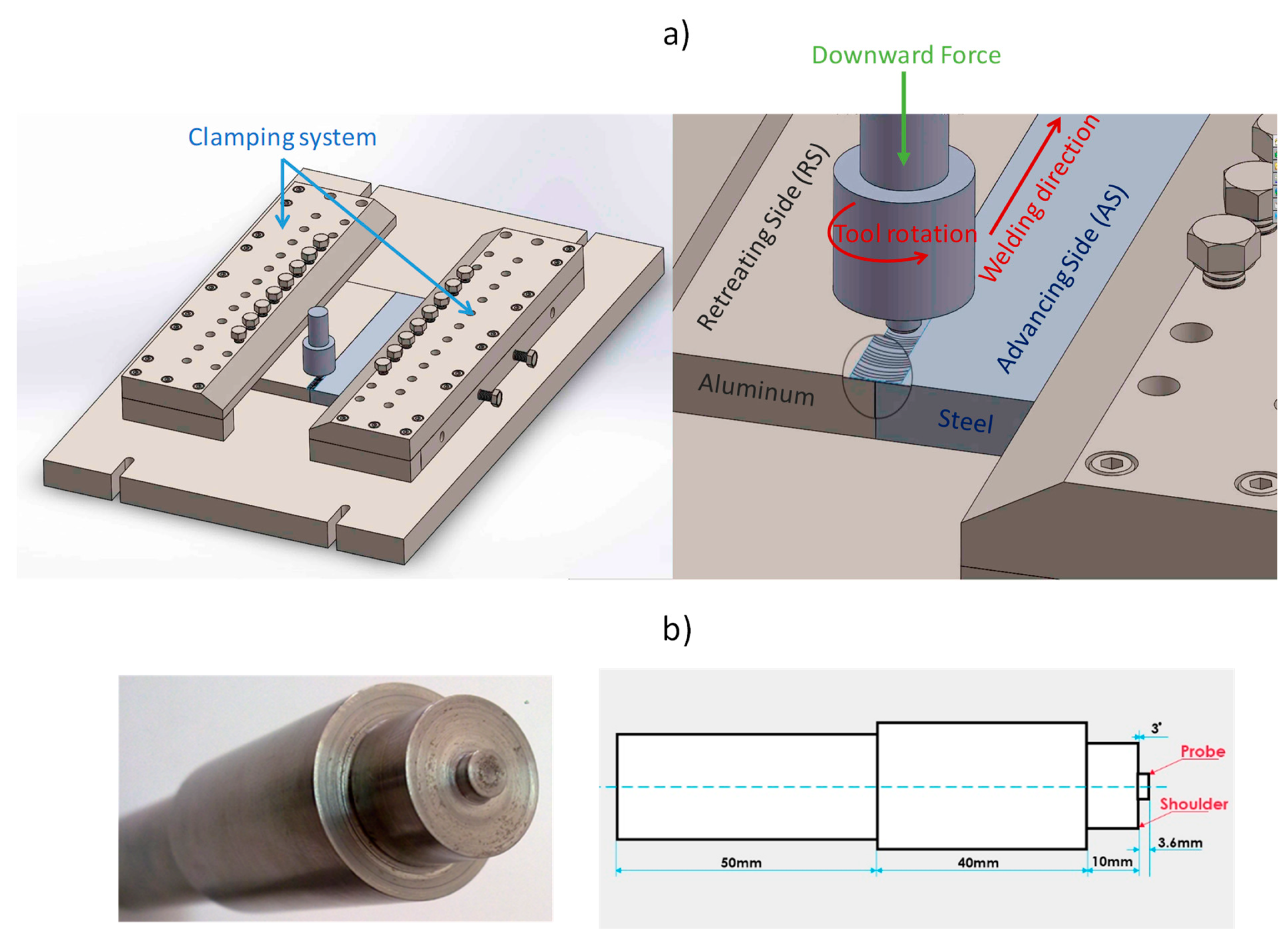
Aluminum alloy (AA2024-T4) and carbon steel (AISI 1018) plates of both 200 mm × 100 mm × 4 mm in dimensions were friction stir butt welded using a homemade gantry type FSW machine (EG-FSW-M1, design and manufacturing supervised by authors at Suez University, Suez, Egypt). The chemical compositions and mechanical properties of these base materials are given in Table 1 and Table 2, respectively. Figure 1a shows the schematic illustrations of the FSW experimental configuration. The tool pin plunged into the soft material AA2024, positioned on the retreating side (RS) with an offset of 0.2 mm, while steel was positioned on the advancing side (AS) to prevent the overheating of aluminum alloy and reducing tool wear. The FSW experiments were carried out at room temperature and using the H13 tool steel composed of a shoulder and unthreaded pin, as shown in Figure 1b. Shoulder diameter, pin diameter, and pin length were 20, 6, and 3.6 mm, respectively. The tool axis was titled by 3° to the normal direction.
In this study, two groups of butt joints were produced. One group at a constant rotation speed and different traverse welding speeds (welds 1, 2, and 3 in Table 3). The second group produced at constant traverse welding speed and different rotation speeds (welds 2, 4, and 5 in Table 4). The FSW process parameters for each butt joint under investigation are listed in Table 3.
2.2. Microstructural Characterization
The welds were sectioned perpendicularly to the welding direction to prepare the metallographic samples and to perform macro/micro-structure characterizations. The cross-sections of the samples were prepared using standard metallography methods. Indeed, they were gently ground using abrasive papers with grades up to 2500, and polished using 0.05 µm Al2O3 suspension. They were then etched using 2% Nital solution for about 8 s. The microstructure analyses of the cross-sections were carried out using optical microscope (OM) Olympus-BX41M-LED, Olympus, Tokyo, Japan and scanning electron microscope (Quanta FEG-250 SEM, FEI company, Hillsboro, OR, USA).
2.3. Mechanical Testing and Failure Investigations
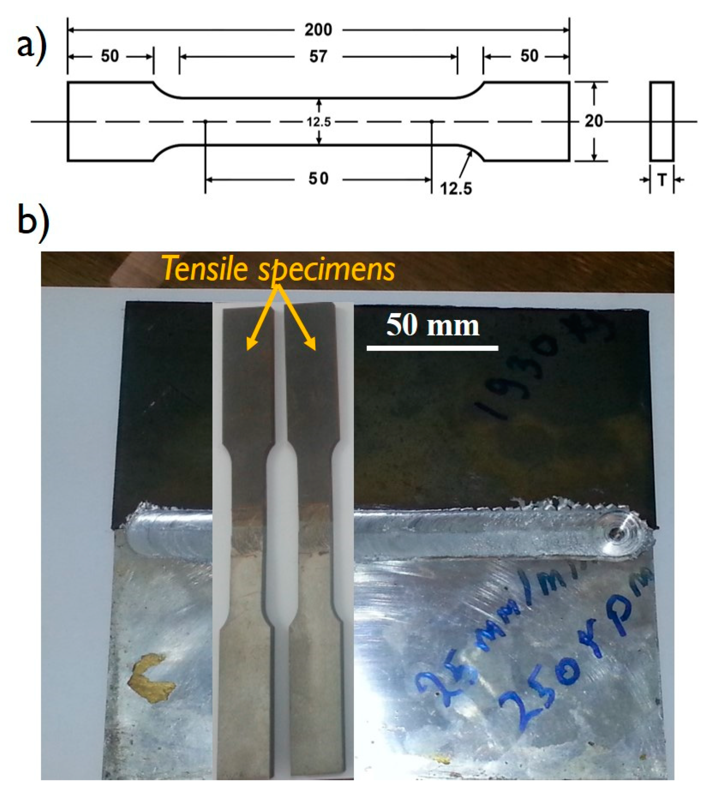
The tensile specimens, two for each weld, were sectioned perpendicularly to the welding direction using a wire electrical discharge machine in accordance with ASTM E8M-04 standard using a 50 mm gage length and their dimensions are shown in Figure 2a. Figure 2b shows the location of the tensile test specimens prepared for the tensile test. The tensile tests were performed at a room temperature using a crosshead speed of 0.1 mm/s using the universal testing machine Instron 4210, Norwood, MA, USA. Fracture morphologies of failed specimens and the phases present at the fracture surface were examined by Quanta 250 with a field emission gun equipped with energy dispersive spectroscopy (EDS) (EDAX, AMETEK, Draper, UT, USA). The Vickers macro-hardness test on the transvers cross-sectional plane of the welds were carried out according to the ASTM: E384-11 standard using load of 2000 gf for 15 s dwell time through the whole processed zone from the Al alloy side through the steel side.
3. Results and Discussion
3.1. Joint Appearance and Macrostructure
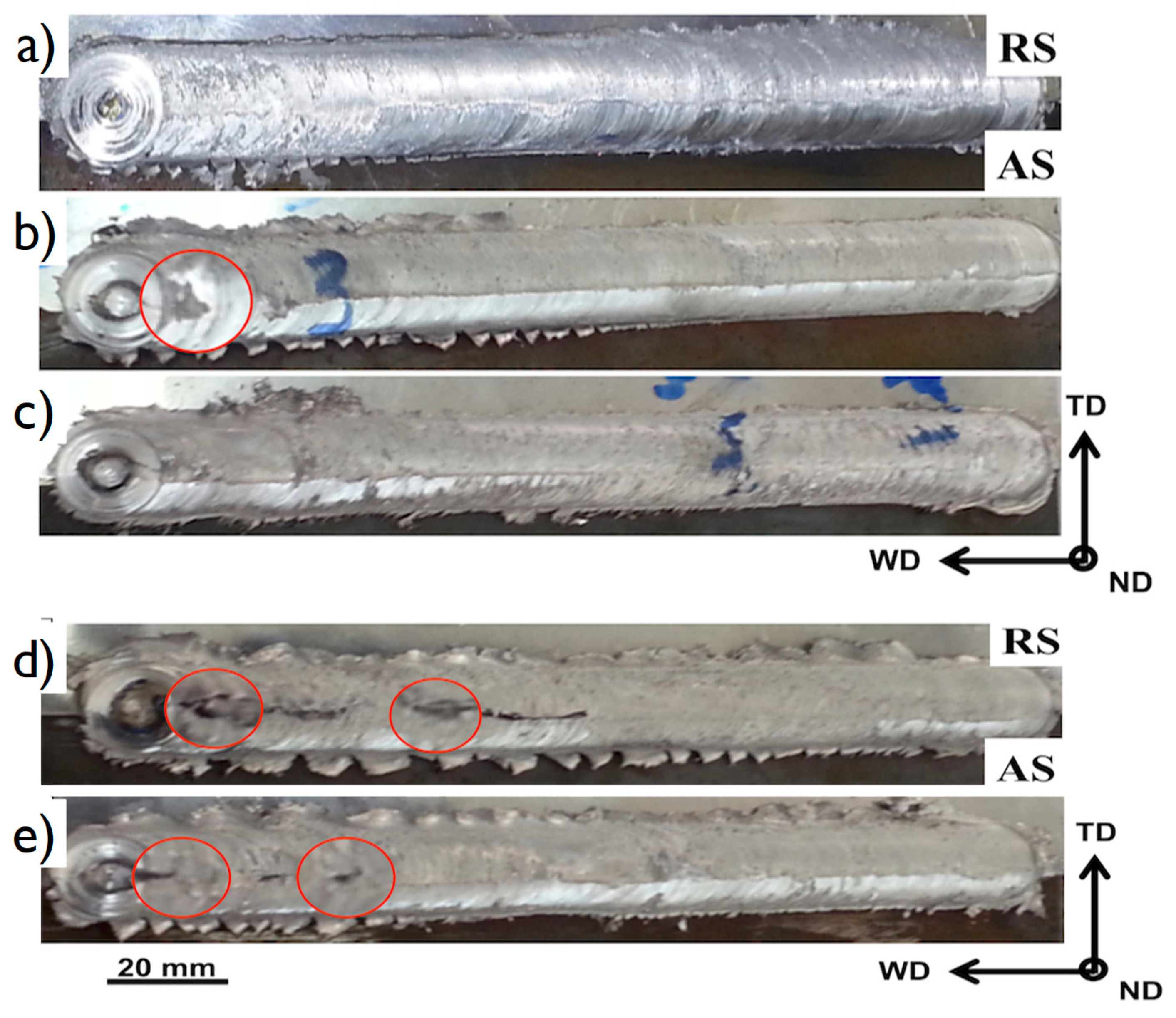
Figure 3 shows the surface appearances of the AA2024/AISI1018 joints welded at different rotation and traverse speeds. This figure shows that all joints welded at 250 rpm rotation speed and different traverse welding speeds are successfully joined without defects such as porosity and cracks (Figure 3a–c). The top surface is smooth, with some flashes observed in both steel and Al sides. However, macro-cracks at the top surface can be seen near the end of the joints produced at 200 and 300 rpm (Figure 3d,e). The joint interface is not vaguely observed at low rotation speed 200 rpm (Figure 3d), and at high traverse speeds of 75 mm/min with 250 rpm rotation speed (Figure 3c).
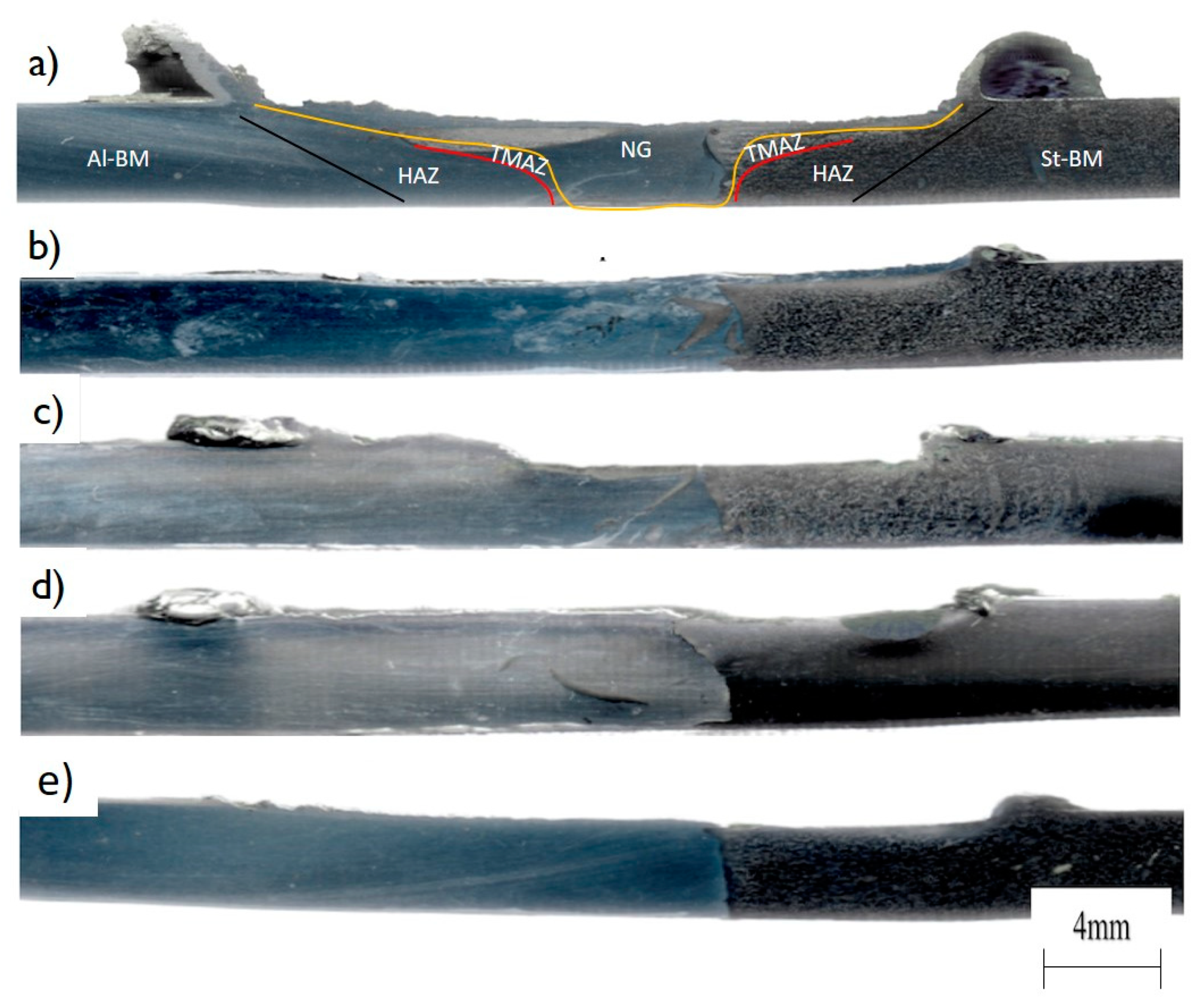
It should be mentioned here that the FSW tool used WAs made from heat-treated tool steel. In order to prevent the sever contact between the tool material and the carbon steel and also to prevent the excessive heat generation that can melt the aluminum, sufficient offset was made towards the aluminum side. Figure 4 shows the macroscopic appearance of the transverse cross-section of the Al/steel joints welded at different conditions. It can be observed that the weld zones between the aluminum and steel are free of any macro-defects and the interface between them can be seen at the different macrographs. The material flow from the steel side to the aluminum side is clearly visible in the weld nugget with the steel fragments in the aluminum side varied in size from a large size (Figure 4a,b,d) to very small size (Figure 4c,e). Due to the offset towards the aluminum side, it can be seen that both materials experienced sufficient stirring in the weld zone, where tiny steel fragments from the advanced side (AS) move to the retreating side (RS) and mixed with the Al, while the aluminum moves from the front of the tool to the back of the tool to generate the joint in the solid state. Recently, Abd Elnabi et al. [36] conducted an experimental investigation to study the dissimilar FSW of pure aluminum AA1050 and annealed low carbon steel. They reported in their optimization step that all joints made at rotational speeds from 255 to 1225 rpm, traverse speed from 422 to 25 mm/min, and pin offset from 0 to 3 mm have sever surface defects. The minimum defect joint was obtained at the high rotation speed of 1550 rpm and at low traverse speed of 17 mm/min. It should be mentioned here that the current study obtained defect free joints at almost all the investigated conditions as the low range of rotation rates and traverse speeds used. This reduced the amount of heat input experienced and enhanced the flow and mixing of the two materials. It can be concluded that the low heat input is required to obtain defect-free joints between aluminum and steel.
3.2. Microstructure Analysis
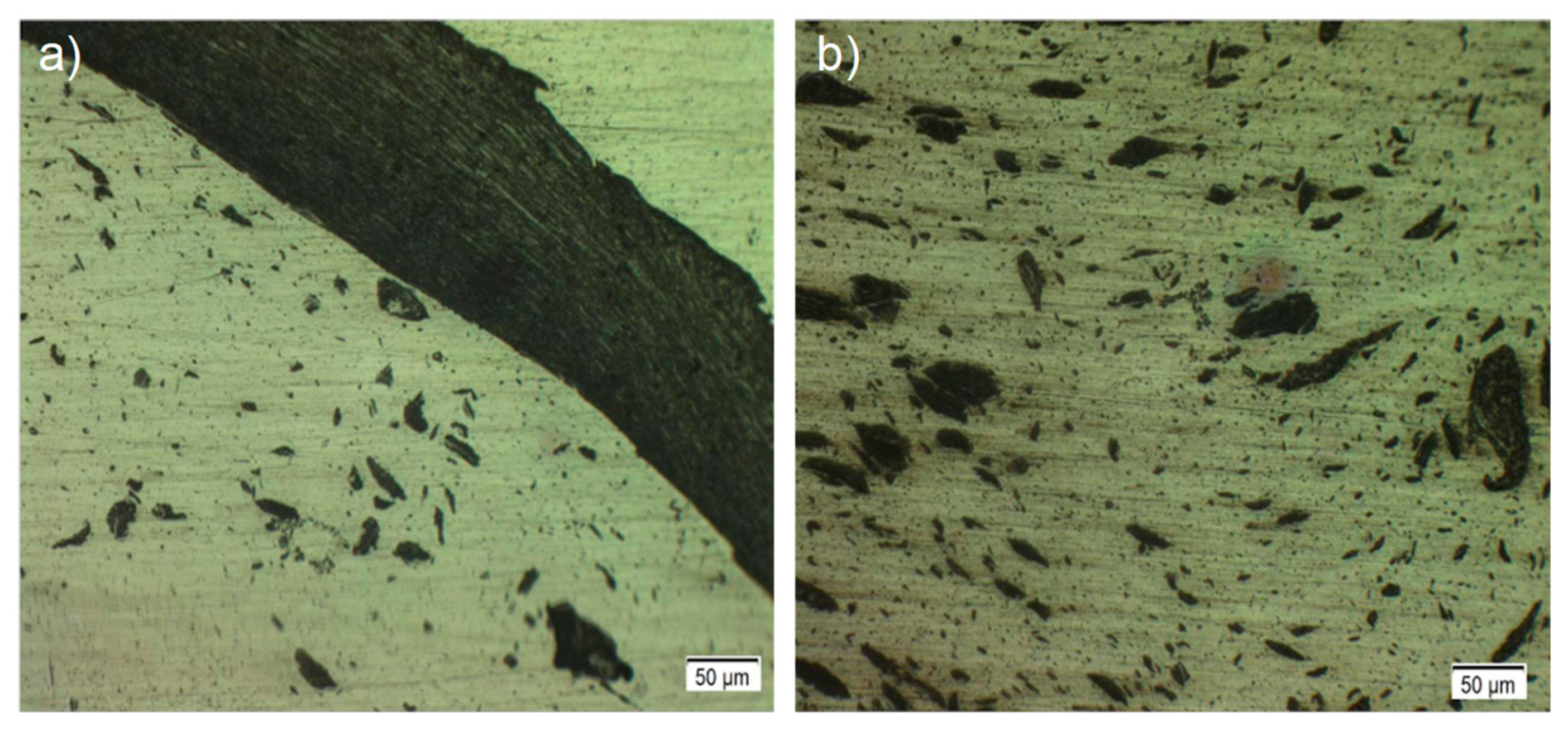
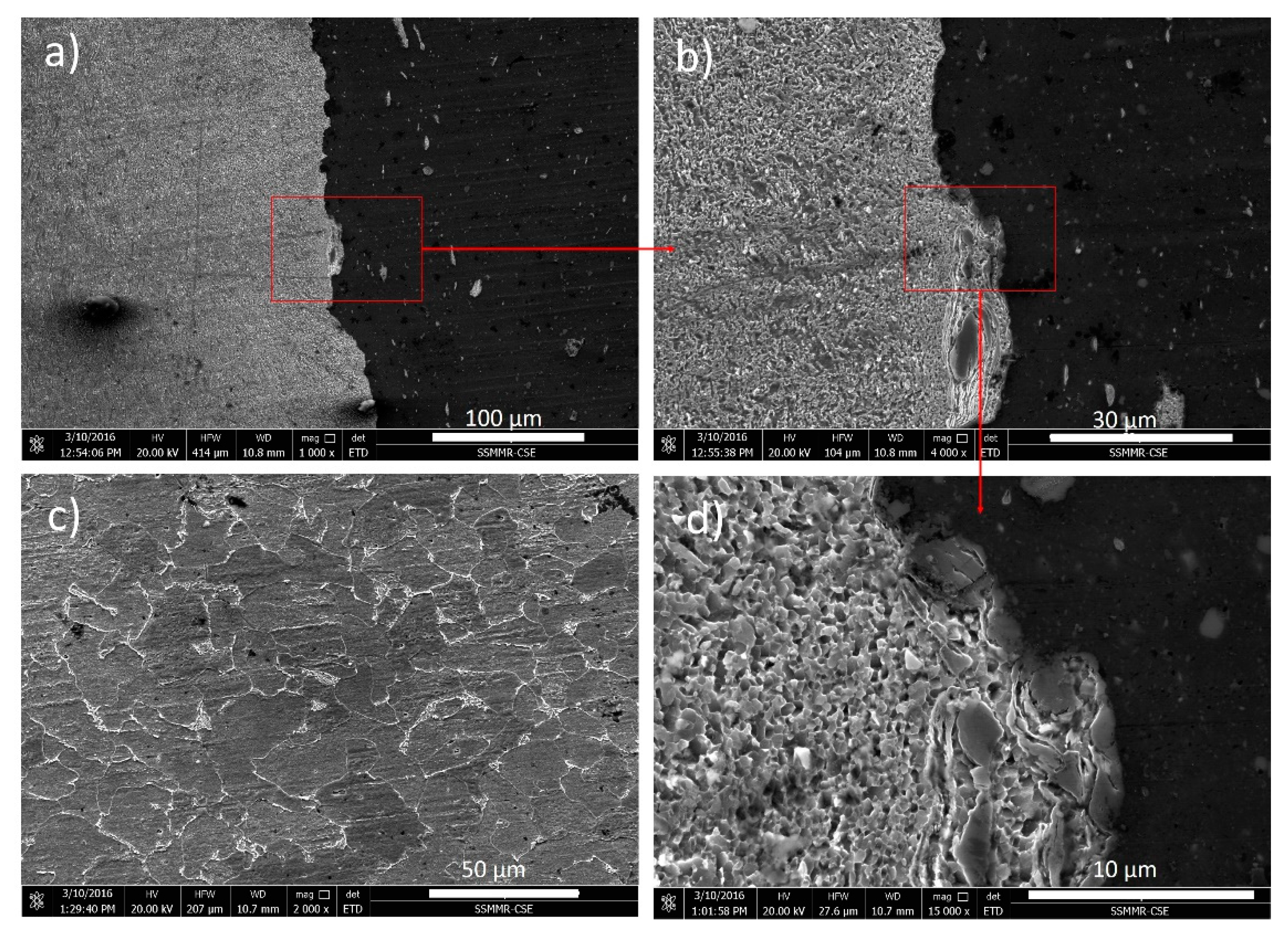
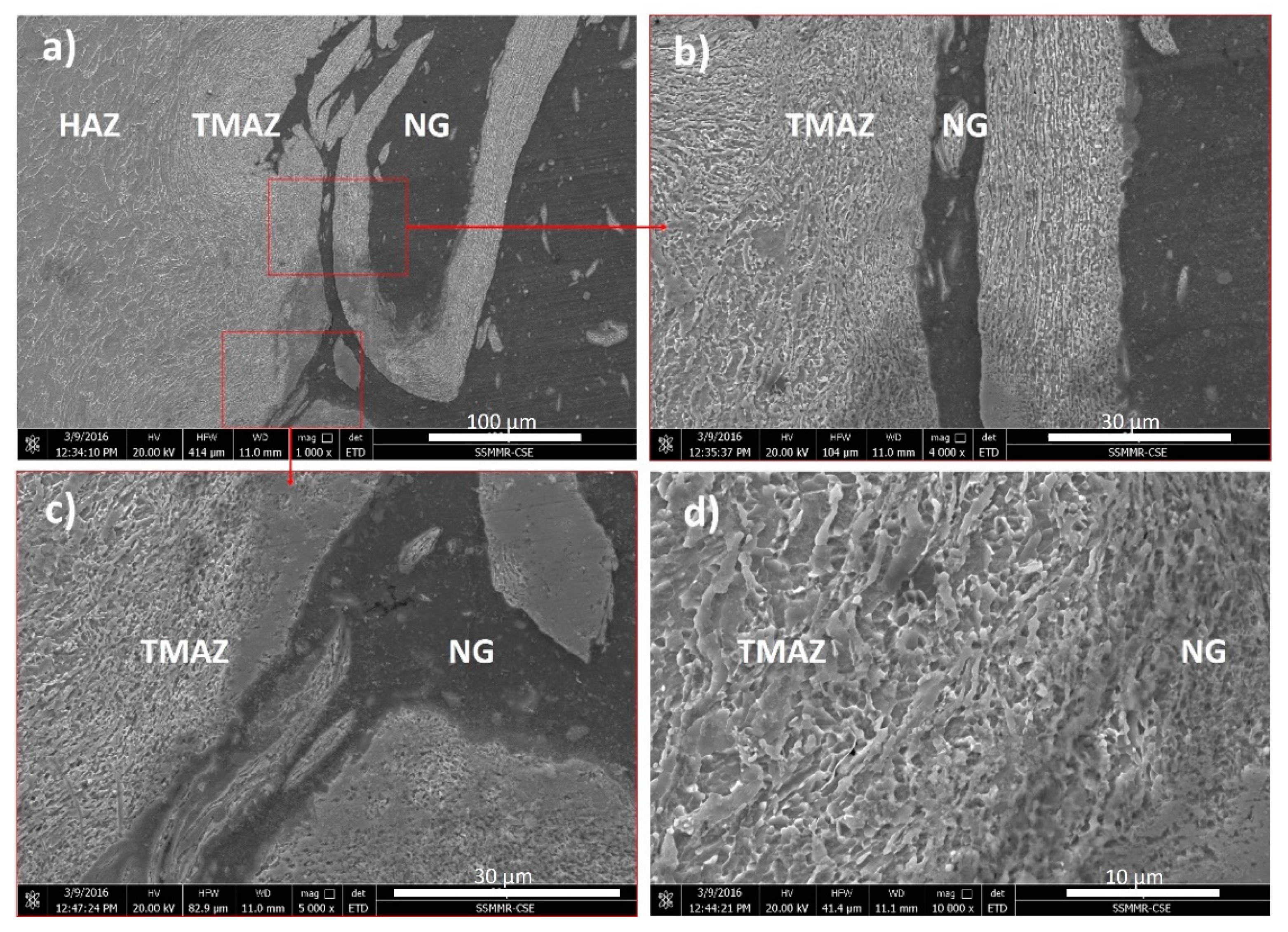
In the case of aluminum alloy FSW, four distinct macrostructural zones, namely the stir zone (SZ), heat affected zone (HAZ), thermo-mechanically affected zone (TMAZ) and base metal (BM) are commonly obtained and reported [10,31,38,39]. In the current case where aluminum and steel undergo dissimilar welding, similar macrostructural features can be observed in the aluminum side in addition to the fragments of steel that these are being mixed with, as can be observed in Figure 5. However, the micro etching used focused mainly on revealing the steel fragments and the SEM was used to trace the microstructural features. Figure 6 shows the SEM micrographs obtained from the joint produced at 200 rpm and at 50 mm/min. It shows different magnification microstructures at the interface between aluminum and steel in Figure 6a,b,d. While Figure 6c shows the BM microstructure, it can be observed that a significant grain refining occurred in the steel and also that the interface has neither micro-cracks or intermetallic compound layer. The fine grains obtained compared to the base material indicates the involved dynamic recrystallization (DRX) mechanism [12,13]. Figure 7 shows the SEM micrographs at the stir zone obtained from the joint produced using 250 rpm and at 25 mm/min in Figure 7a–c. While Figure 7d shows the interface between the SZ and the TMAZ, it can be noted that an intimate bonding occurred between Al and steel through the mixing of the steel fragments with the aluminum and the metallurgical bonding occurs through the diffusion of atoms of both metals in each other. The TMAZ (Figure 7d) is characterized by immensely deformed and elongated grains revealing that the material has been plastically deformed along the rotating direction of the pin tool.
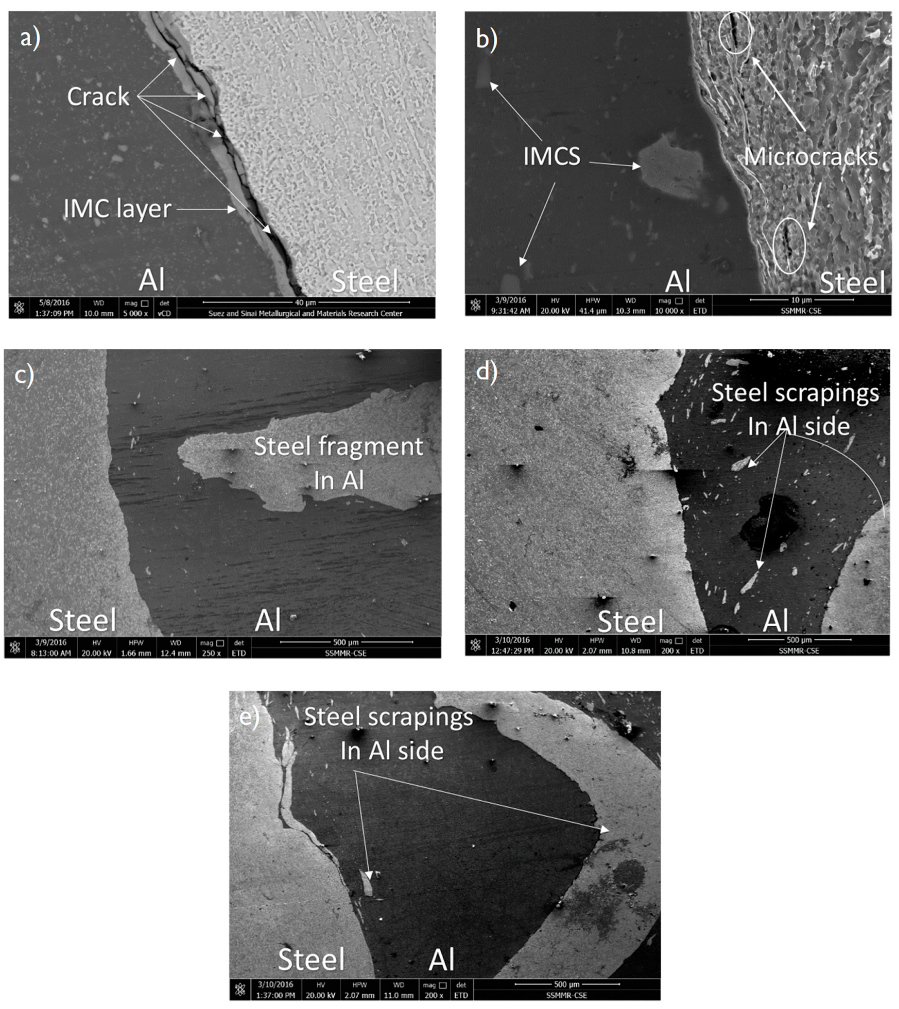
Due to the potential formation of the brittle IMCs, the Al/steel interface is considered a critical zone. Indeed, the presence of IMCs leads to a significant reduction in the weld joint strength. In this study, the effect of traverse and rotation speeds on the IMCs formation at the Al/steel interface was investigated. Figure 8 illustrates the SEM micrographs on the Al/steel joint interfaces under investigation.
At the traverse speed of 25 mm/min, there are some micro-cracks and a continuous a layer of IMC with 2 μm thickness formed at the Al/steel interface as shown in Figure 8a, which can facilitate crack propagation along the Al/steel interface. By increasing the traverse speed to 50 mm/min, it is observed that there are micro-cracks formed on the steel side in SZ and also a few steel fragments on the Al side (Figure 8b). However, there is no IMC layer formed at the Al/steel interface, but larger IMCs have been formed on the Al side which range from 0.6 to 6 µm. At the higher traverse speed of 75 mm/min, Figure 8c revels that a defect-free weld with no voids and micro-cracks are formed. A long steel fragment is observed in the Al side and there is no evidence of IMCs at the Al/steel interface. Accordingly, increasing the traverse speed from 25 to 75 mm/min eliminate the IMCs. Liu et al. [4] showed that in the FSW of 6061-T6 and advanced high strength steel, lower welding speed can increase the thickness of the intermetallic layer due to the longer high temperature period experienced.
At the rotation speed of 200 rpm, Figure 8d reveals that many steel fragments with different sizes scattered into the Al side were formed without any IMCs at the Al/steel interface. However, some IMCs formed between Fe and Al far away from the interface. Increasing the rotation speed to 300 rpm, Figure 8e showed that a little amount of steel fragments with different sizes scattered into the Al side were formed. Few IMCs are formed at the Al/steel interface which measured about 1 µm. Indeed, increasing the rotation speed will increase the heat input created by the friction between the workpiece and the shoulder and then resulted in the formation of IMCs [1]. Only at the lowest welding speed of 25 mm/min and rotation speed of 250 rpm an IMC of 2 µm layer thickness is observed due to the highest heat input experienced of about 79 J/mm. The IMC thickness formed during the friction stir butt welding of aluminum alloy to steel ranges between 0.25 and 5 μm [40,41,42]. This IMC thickness compared to that obtained in other studies [36] for aluminum steel FSW can be considered low. This is attributed to the low tool rotation rates used in this study which significantly reduced the heat input experienced during the welding process.
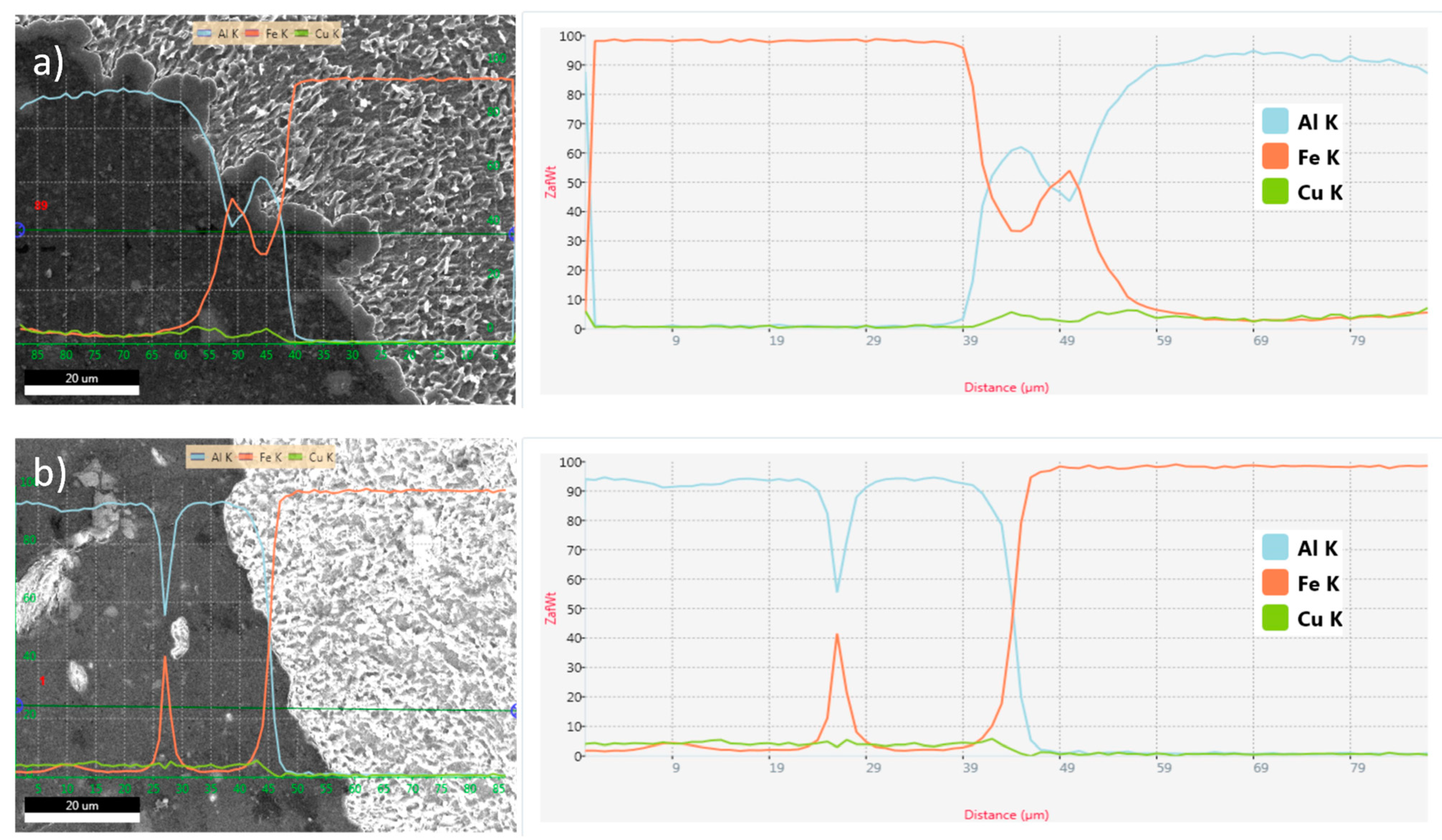
To investigate the type of IMCs, SEM and EDS analysis were conducted. According to the EDS line analyses of Fe and Al and the Fe–Al binary phase diagram the intermetallic layer formed at a traverse speed of 25 mm/min consisted of Al-rich FeAl3 and has a thickness up to 2 µm, as shown in Figure 9. It has been reported that the Al-rich IMCs are more brittle than the Fe-rich ones [30,43]. These brittle Al-rich IMCs are detrimental to the mechanical performance of the joint [34,44]. Watanabe et al. [34] showed that the presence of the brittle Al-rich FeAl3 leads to a decrease in the joint strength. Figure 9b confirms that no intermetallic compounds were formed at the Al/steel interface for 50 mm/min and 200 rpm.
To summarize, higher traverse speed and lower rotation speed do not promote the formation of IMCs at the Al/steel, however, they produce a large amount of steel fragments on the Al side. At lower travel speed (25 mm/min), a continuous layer of IMC is formed at the Al/steel interface.
3.3. Mechanical Properties
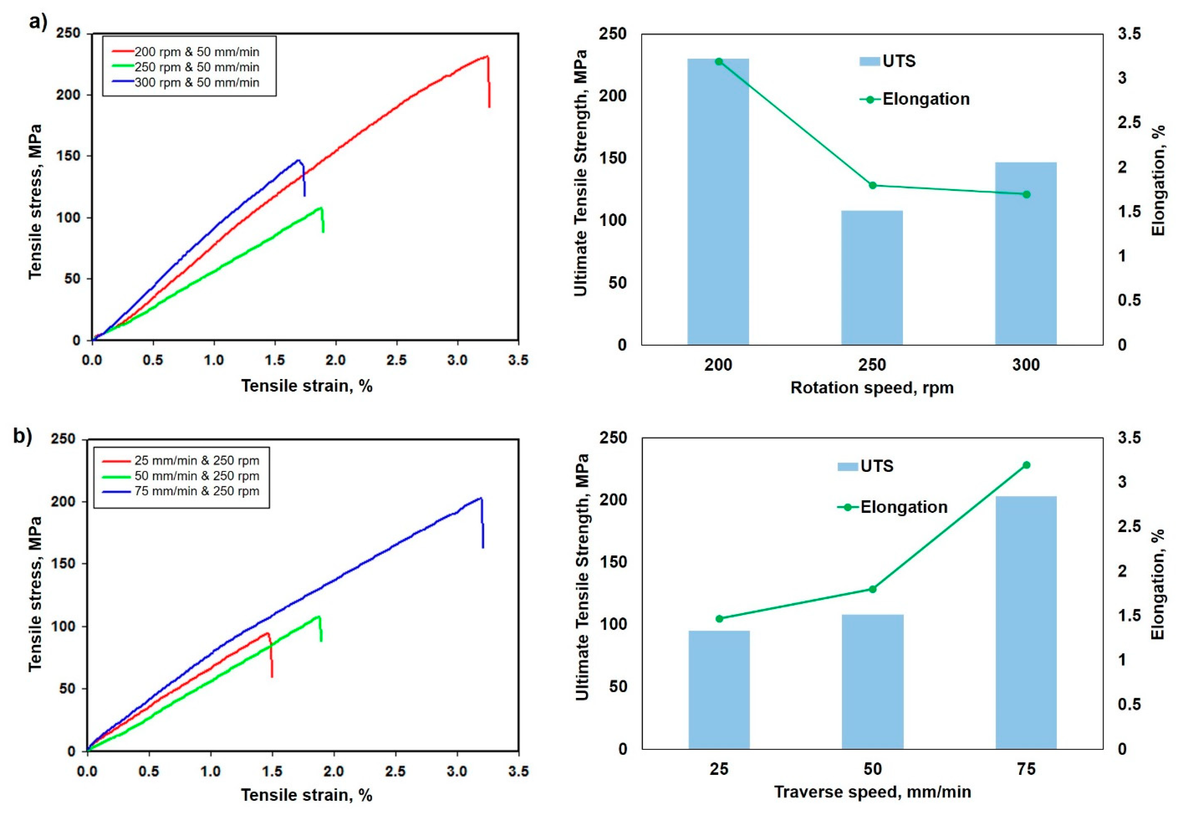
The tensile tests were conducted for all investigated FSWed dissimilar joints. Figure 10a shows the tensile stress–strain curves and the ultimate tensile strength (UTS) and elongation results of the joints welded at three different rotation speeds of 200, 250 and 300 rpm and at a constant traverse speed of 50 mm/min. From Figure 10a, the maximum tensile strength of 230 MPa was obtained at a 200 rpm along with a 3.2% elongation at fracture. By increasing the rotation speed to 250 rpm, the joint strength decreases and reaches the lowest tensile strength of 108 MPa along with 1.8% elongation at fracture. The joint processed at 300 rpm provided a tensile strength of 147 MPa along with 1.7% elongation at fracture. Indeed, according to the Table 4, which summarizes the amount of heat input, and the IMCs generated at Al/steel interface and fracture position for each rotation speed under investigated. It is interesting to note that the strength decreases as the heat input increases (i.e., as the rotation speed increases). Moreover, there is no IMC formed at the Al/steel interface.
Figure 10b shows the tensile stress–strain curves and UTS and elongation results of joints welded at three different traverse speeds of 25, 50 and 75 mm/min and at constant rotation speed of 250 rpm. From Figure 10b, the maximum tensile strength of 203 MPa was obtained at 75 mm/min due the absence of IMCs at the Al/steel interface. By decreasing the traverse speed to 50 mm/min, the joint strength decreases and reaches a tensile strength of 108 MPa. The joint processed at 25 mm/min provided the lowest tensile strength. Table 5 summarizes the amount of heat input, and the IMCs generated at the Al/steel interface and fracture position for each traverse speed under investigated. The table shows that the strength increases with the traverse speed increasing from 25 to 75 mm/min as the heat input amount decreases. Wang et al. [40] showed that the strength of defect-free joints increased with reduction in IMC thickness. Ultimate tensile strength of 289 MPa (90% of base aluminum alloy) was achieved at the tool rotation rate of 500 rpm and traverse speed of 15 mm/min.
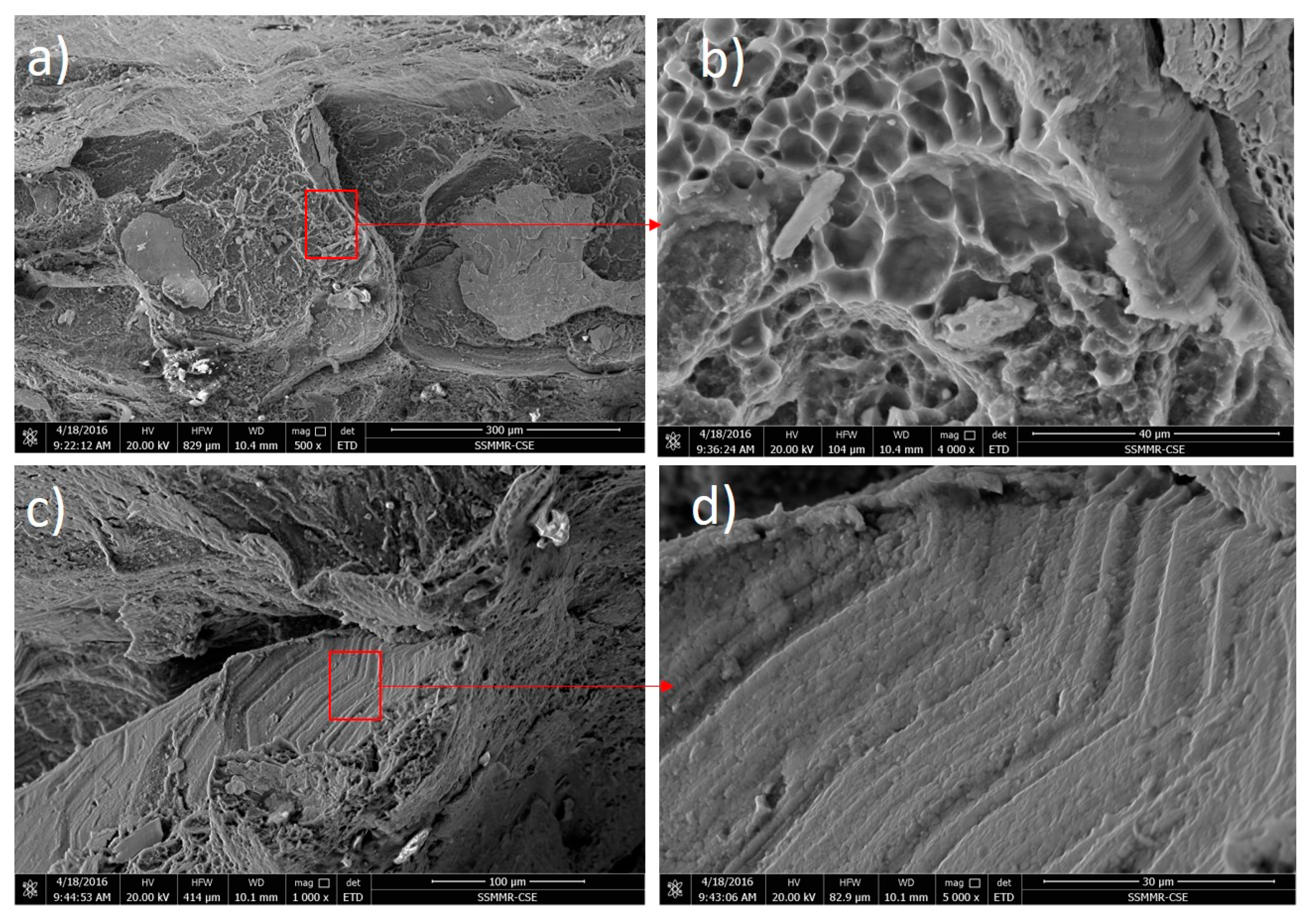
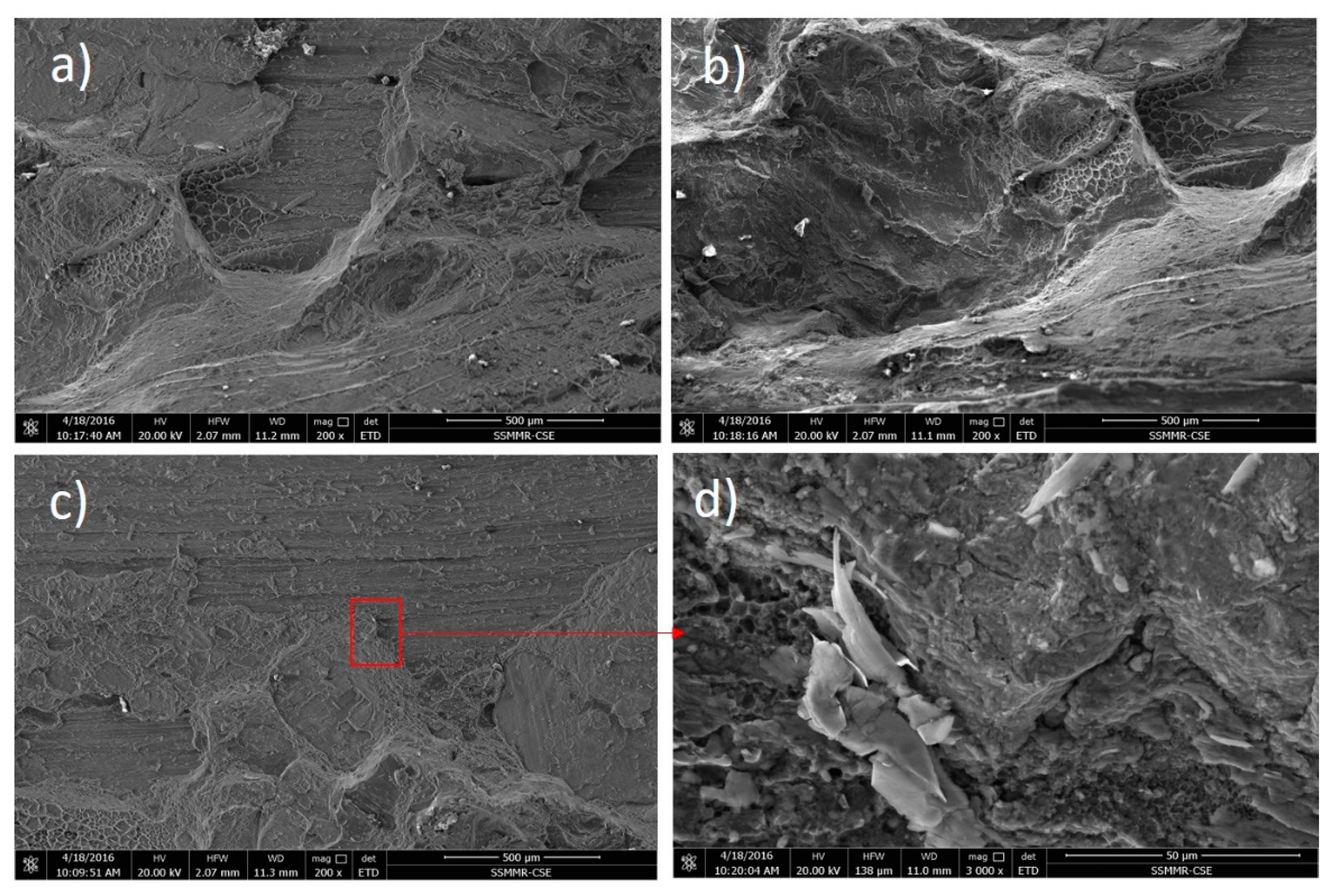
To investigate the failure mode, the highest tensile strength joint (200 rpm and 50 mm/min) and the lowest tensile strength joint (250 rpm and 25 mm/min) tensile specimens fracture surfaces were examined using SEM imaging. Figure 11 shows the SEM micrographs of the fracture surface of FSWed joints welded at 200 rpm and 50 mm/min at different positions. Figure 11a,b show low and high magnification for a dimple feature position and Figure 11c,d show low and high magnification in cleavage a fracture position. It can be observed that there is a mixed mode fracture characterized by dimples (Figure 11a,b) and cleavage (Figure 11c,d). Figure 12 shows the SEM micrographs of the fracture surface of the FSWed joints welded at 250 rpm and 25 mm/min at different positions. Figure 12a,b show low magnification and high magnification for mixed fracture mode features and Figure 12c,d show low and high magnification for high-density IMC positions. It can be noted that the fracture of high tensile strength sample is dominated by ductile fracture with little features of the brittle fracture, whereas the fracture low tensile strength sample is dominated by brittle fracture mode with a little ductile fracture feature. This is consistent with the obtained tensile strength values. The bimodal behavior was reported by Zandsalimi et al. [45] when investigating the dissimilar FSW of 430 stainless steel and 6061 aluminum alloy. These showed that this bimodal fracture occurs in the aluminum HAZ, which has the lowest hardness.
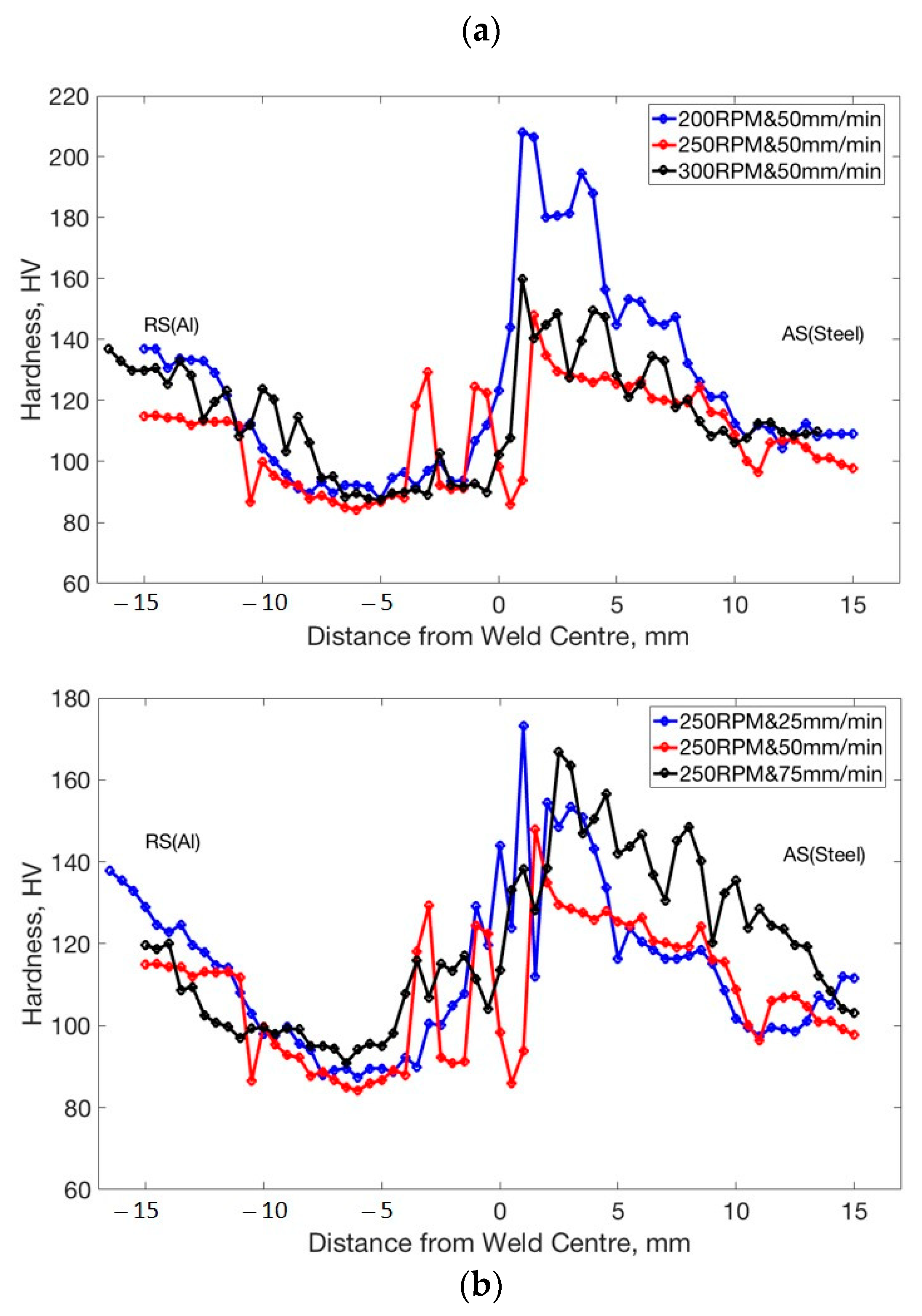
Figure 13 shows the hardness profile across the FSWed joint interface that was measured at the same position for all samples. This figure reveals two distinct hardness profiles at the retreating side (Al) and advancing side (steel) due to the difference in the material properties of steel and Al. At the Al side, the hardness values of the stirred zone (SZ), thermo-mechanically affected zone (TMAZ), and heat affected zone (HAZ) are lower than the base material due to the softening which occurred during the high thermal cycle experienced which causes the dissolution of the hardening precipitates in the TMAZ and coarsening in the HAZ/SZ region. It was reported that the coarsening and dissolution of strengthening precipitates during the thermal cycle of the FSW cause softening [15,38,46,47,48,49,50]. However, IMCs and steel fragments in the Al side cause peaks of hardness in the weld zone as observed in the joint of 250 rpm and 50 mm/min. At the steel side, the hardness values of SZ, TMAZ, and HAZ are higher than the base material. This can be due to the grain refining which occurs due to the stirring action in the stir zone and also due to the fast cooling occurring through the aluminum of high thermal conductivity. Thus, the peak hardness values appear at SZ.
4. Conclusions
In this study, 4 mm-thick AA2024 and AISI 1018 were friction stir butt welded. The welding was carried out at rotation speeds of 200, 250, 300 rpm and welding speeds of 25, 50, and 75 mm/min. After the careful characterization of the joints, the following conclusions can be outlined:
- Defect-free joints are obtained at a rotation rate of 250 rpm with the different welding speeds applied and also 200 rpm with 50 mm/min;
- The key factor in the intermetallic formation at the interface between Al/steel is the level of heat input experienced during FSW. Reducing the heat input through either the increase in the welding speed up to 75 mm/min or reducing the rotation rate up to 200 mm/min eliminates the IMCs formation. Only at the lowest welding speed of 25 mm/min is an IMC of 2 µm layer thickness observed due to the highest heat input experienced of about 79 J/mm.
- The maximum tensile strength of the joint is achieved (~230 MPa) at low rotation speed (200 rpm) along with 3.2% elongation. No IMCs are formed at this condition due to the lowest amount of heat input experienced (22.32 J/mm).
- Fracture surface of the highest (200 rpm and 50 mm/min) and lowest (250 rpm and 25 mm/min) tensile strength joints were investigated using SEM. Both showed mixed-mode fracture mechanism characterized by cleavage pattern and dimples. However, in the lowest tensile sample, the IMCs played a significant role in the failure acceleration.
- The hardness at the aluminum side showed the conventional behavior of the precipitation hardened alloys with a reduction in hardness in the weld zone to values below 90 Hv from about 140 Hv; however, a significant increase in the hardness of the steel side up to 150 Hv from about 120 Hv is observed, which could be due to the grain refining observed.
Author Contributions
Data curation, M.M.Z.A., M.M.E.-S.S. and M.J.; formal analysis, M.M.Z.A., N.J., M.M.E.-S.S. and B.A.; investigation, M.M.Z.A., M.M.E.-S.S. and M.J.; methodology, M.M.Z.A., M.M.E.-S.S. and M.J.; software, N.J. and B.A. supervision, M.M.Z.A. and M.M.E.-S.S.; visualization, N.J. and B.A.; writing—original draft, M.M.Z.A., M.M.E.-S.S. and M.J.; writing—review and editing, M.M.Z.A., M.J., B.A. and M.M.E.-S.S. All authors have read and agreed to the published version of the manuscript.
Funding
This research received no external funding.
Institutional Review Board Statement
Not applicable.
Informed Consent Statement
Not applicable.
Data Availability Statement
The data presented in this study are available on request from the corresponding author. The data are not publicly available due to the extremely large size.
Acknowledgments
The authors would like to thank Mohamed Refat at the BUE for his assistance in the drawings of Figure 1.
Conflicts of Interest
The authors declare no conflict of interest.
References
- Pourali, M.; Abdollah-zadeh, A.; Saeid, T.; Kargar, F. Influence of Welding Parameters on Intermetallic Compounds Formation in Dissimilar Steel/Aluminum Friction Stir Welds. J. Alloys Compd. 2017, 715, 1–8. [Google Scholar] [CrossRef]
- Piccini, J.M.; Svoboda, H.G. Effect of Pin Length on Friction Stir Spot Welding (FSSW) of Dissimilar Aluminum-Steel Joints. Procedia Mater. Sci. 2015, 9, 504–513. [Google Scholar] [CrossRef] [Green Version]
- Khodir, S.A.; Ahmed, M.M.Z.; Ahmed, E.; Mohamed, S.M.R.; Abdel-Aleem, H. Effect of Intermetallic Compound Phases on the Mechanical Properties of the Dissimilar Al/Cu Friction Stir Welded Joints. J. Mater. Eng. Perform. 2016, 25, 4637–4648. [Google Scholar] [CrossRef]
- Liu, X.; Lan, S.; Ni, J. Analysis of Process Parameters Effects on Friction Stir Welding of Dissimilar Aluminum Alloy to Advanced High Strength Steel. Mater. Des. 2014, 59, 50–62. [Google Scholar] [CrossRef]
- Springer, H.; Kostka, A.; Payton, E.J.; Raabe, D.; Kaysser-Pyzalla, A.; Eggeler, G. On the Formation and Growth of Intermetallic Phases during Interdiffusion between Low-Carbon Steel and Aluminum Alloys. Acta Mater. 2011, 59, 1586–1600. [Google Scholar] [CrossRef]
- Coelho, R.S.; Kostka, A.; dos Santos, J.F.; Kaysser-Pyzalla, A. Friction-Stir Dissimilar Welding of Aluminium Alloy to High Strength Steels: Mechanical Properties and Their Relation to Microstructure. Mater. Sci. Eng. A 2012, 556, 175–183. [Google Scholar] [CrossRef]
- Tanaka, T.; Hirata, T.; Shinomiya, N.; Shirakawa, N. Analysis of Material Flow in the Sheet Forming of Friction-Stir Welds on Alloys of Mild Steel and Aluminum. J. Mater. Process. Technol. 2015, 226, 115–124. [Google Scholar] [CrossRef]
- Tamadon, A.; Pons, D.J.; Clucas, D.; Zealand, N. Ebsd Characterization of Bobbin Friction Stir Welding of Aa6082-T6 Aluminium Alloy. Adv. Mater. Sci. 2020, 20. [Google Scholar] [CrossRef]
- Ahmed, M.M.Z.; Ahmed, E.; Hamada, A.S.; Khodir, S.A.; El-Sayed Seleman, M.M.; Wynne, B.P. Microstructure and Mechanical Properties Evolution of Friction Stir Spot Welded High-Mn Twinning-Induced Plasticity Steel. Mater. Des. 2016, 91, 378–387. [Google Scholar] [CrossRef]
- Ahmed, M.M.Z.; Wynne, B.P.; Rainforth, W.M.; Addison, A.; Martin, J.P.; Threadgill, P.L. Effect of Tool Geometry and Heat Input on the Hardness, Grain Structure, and Crystallographic Texture of Thick-Section Friction Stir-Welded Aluminium. Metall. Mater. Trans. A 2019, 50, 271–284. [Google Scholar] [CrossRef]
- Ahmed, M.M.Z.; Elnaml, A.; Shazly, M.; Seleman, M.M.E. The Effect of Top Surface Lubrication on the Friction Stir Welding of Polycarbonate Sheets. Intern. Polym. Process. 2021, 1–9. [Google Scholar] [CrossRef]
- Ahmed, M.M.Z.M.Z.; Ataya, S.; El-Sayed Seleman, M.M.M.; Ammar, H.R.R.; Ahmed, E. Friction Stir Welding of Similar and Dissimilar AA7075 and AA5083. J. Mater. Process. Technol. 2017, 242, 77–91. [Google Scholar] [CrossRef]
- Ahmed, M.M.Z.; Wynne, B.P.; El-Sayed Seleman, M.M.; Rainforth, W.M. A Comparison of Crystallographic Texture and Grain Structure Development in Aluminum Generated by Friction Stir Welding and High Strain Torsion. Mater. Des. 2016, 103, 259–267. [Google Scholar] [CrossRef]
- Buffa, G.; Fratini, L.; Hua, J.; Shivpuri, R. Friction Stir Welding of Tailored Blanks: Investigation on Process Feasibility. CIRP Ann. 2006, 55, 2–5. [Google Scholar] [CrossRef]
- Ahmed, M.M.Z.; Seleman, M.M.E.; Zidan, Z.A.; Ramadan, R.M.; Ataya, S.; Alsaleh, N.A. Microstructure and Mechanical Properties of Dissimilar Friction Stir Welded AA2024-T4/AA7075-T6 T-Butt Joints. Metals 2021, 11, 128. [Google Scholar] [CrossRef]
- Mishra, R.S.; Ma, Z.Y. Friction Stir Welding and Processing. Mater. Sci. Eng. R 2005, 50, 1–78. [Google Scholar] [CrossRef]
- Miles, M.P.; Nelson, T.W.; Steel, R.; Olsen, E.; Gallagher, M. Effect of Friction Stir Welding Conditions on Properties and Microstructures of High Strength Automotive Steel. Sci. Technol. Weld. Join. 2009, 14, 228–232. [Google Scholar] [CrossRef]
- Ataya, S. Load Carrying Capacity And Microstructure Of Resistance Spot Welded Dual-Phase (Dp600) Steel. In Characterization of Minerals, Metals, and Materials; Carpenter, J.S., Bai, C., Hwang, J.-Y., Eds.; John Wiley & Sons: New York, NY, USA, 2014; pp. 297–304. [Google Scholar]
- Hwang, I.H.; Watanabe, T.; Doi, Y. Dissimilar Metal Welding of Steel to Al-Mg Alloy by Spot Resistance Welding. Adv. Mater. Res. 2007, 15–17, 381–386. [Google Scholar] [CrossRef]
- Qiu, R.; Iwamoto, C.; Satonaka, S. Interfacial Microstructure and Strength of Steel/Aluminum Alloy Joints Welded by Resistance Spot Welding with Cover Plate. J. Mater. Process. Technol. 2009, 209, 4186–4193. [Google Scholar] [CrossRef]
- Zhang, W.; Sun, D.; Han, L.; Liu, D. Interfacial Microstructure and Mechanical Property of Resistance Spot Welded Joint of High Strength Steel and Aluminium Alloy with 4047 AlSi12 Interlayer. Mater. Des. 2014, 57, 186–194. [Google Scholar] [CrossRef]
- Habibnia, M.; Shakeri, M.; Nourouzi, S.; Givi, M.K.B. Microstructural and Mechanical Properties of Friction Stir Welded 5050 Al Alloy and 304 Stainless Steel Plates. Int. J. Adv. Manuf. Technol. 2014, 76, 819–829. [Google Scholar] [CrossRef]
- Haddadi, F.; Abu-Farha, F. Microstructural and Mechanical Performance of Aluminium to Steel High Power Ultrasonic Spot Welding. J. Mater. Process. Technol. 2015, 225, 262–274. [Google Scholar] [CrossRef]
- Tricarico, L.; Spina, R. Experimental Investigation of Laser Beam Welding of Explosion-Welded Steel/Aluminum Structural Transition Joints. Mater. Des. 2010, 31, 1981–1992. [Google Scholar] [CrossRef]
- Wang, P.; Chen, X.; Pan, Q.; Madigan, B.; Long, J. Laser Welding Dissimilar Materials of Aluminum to Steel: An Overview. Int. J. Adv. Manuf. Technol. 2016, 87, 3081–3090. [Google Scholar] [CrossRef]
- Roulin, M.; Luster, J.W.; Karadeniz, G.; Mortensen, A. Strength and Structure of Furnace-Brazed Joints between Aluminum and Stainless Steel. Weld. J. 1999, 78, 151-s. [Google Scholar]
- Cao, R.; Sun, J.H.; Chen, J.H.; Wang, P.-C. Cold Metal Transfer Joining of Aluminum AA6061-T6-to-Galvanized Boron Steel. J. Manuf. Sci. Eng. 2014, 136. [Google Scholar] [CrossRef]
- Cao, R.; Yu, G.; Chen, J.H.; Wang, P.C. Cold Metal Transfer Joining Aluminum Alloys-to-Galvanized Mild Steel. J. Mater. Process. Technol. 2013, 213, 1753–1763. [Google Scholar] [CrossRef]
- Peng, L.; Yajiang, L.; Juan, W.; Jishi, G. Vacuum Brazing Technology and Microstructure near the Interface of Al/18-8 Stainless Steel. Mater. Res. Bull. 2003, 38, 1493–1499. [Google Scholar] [CrossRef]
- Nandan, R.; Debroy, T.; Bhadeshia, H.K.D.H. Recent Advances in Friction-Stir Welding–Process, Weldment Structure and Properties. Prog. Mater. Sci. 2008, 53, 980–1023. [Google Scholar] [CrossRef] [Green Version]
- Refat, M.; Elashery, A.; Toschi, S.; Ahmed, M.M.Z.; Morri, A.; El-Mahallawi, I.; Ceschini, L. Microstructure, Hardness and Impact Toughness of Heat-Treated Nanodispersed Surface and Friction Stir-Processed Aluminum Alloy AA7075. J. Mater. Eng. Perform. 2016, 25, 5087–5101. [Google Scholar] [CrossRef]
- Shen, Z.; Chen, Y.; Haghshenas, M.; Gerlich, A.P. Role of Welding Parameters on Interfacial Bonding in Dissimilar Steel/Aluminum Friction Stir Welds. Eng. Sci. Technol. Int. J. 2015, 18, 270–277. [Google Scholar] [CrossRef] [Green Version]
- Threadgill, P.L.; Leonard, A.J.; Shercliff, H.R.; Withers, P.J. Friction Stir Welding of Aluminium Alloys. Int. Mater. Rev. 2009, 54, 49–93. [Google Scholar] [CrossRef]
- Watanabe, T.; Takayama, H.; Yanagisawa, A. Joining of Aluminum Alloy to Steel by Friction Stir Welding. J. Mater. Process. Technol. 2006, 178, 342–349. [Google Scholar] [CrossRef]
- Chen, T. Process Parameters Study on FSW Joint of Dissimilar Metals for Aluminum-Steel. J. Mater. Sci. 2009, 44, 2573–2580. [Google Scholar] [CrossRef]
- Abd, M.M.; Osman, T.A.; El Mokadem, A.; Bakr, A. Evaluation of the Formation of Intermetallic Compounds at the Intermixing Lines and in the Nugget of Dissimilar Steel/Aluminum Friction Stir Welds. J. Mater. Res. Technol. 2020, 9, 10209–10222. [Google Scholar] [CrossRef]
- ASM International. ASM Handbook Volume 1: Properties and Selection: Irons, Steels, and High-Performance Alloys, 10th ed.; ASM International: Materials Park, OH, USA, 1990; ISBN 0-87170-380-7. [Google Scholar]
- Ahmed, M.M.Z.; Wynne, B.P.; Rainforth, W.M.; Threadgill, P.L. Microstructure, Crystallographic Texture and Mechanical Properties of Friction Stir Welded AA2017A. Mater. Charact. 2012, 64, 107–117. [Google Scholar] [CrossRef]
- Zayed, E.M.; El-Tayeb, N.S.M.; Ahmed, M.M.Z.; Rashad, R.M. Development and Characterization of AA5083 Reinforced with SiC and Al2O3 Particles by Friction Stir Processing. In Engineering Design Applications; Springer: Cham, Switzerland, 2019; Volume 92. [Google Scholar]
- Wang, T.; Komarasamy, M.; Liu, K.; Mishra, R.S. Materials Science & Engineering A Friction Stir Butt Welding of Strain-Hardened Aluminum Alloy with High Strength Steel. Mater. Sci. Eng. A 2018, 737, 85–89. [Google Scholar] [CrossRef]
- Tanaka, T.; Morishige, T.; Hirata, T. Comprehensive Analysis of Joint Strength for Dissimilar Friction Stir Welds of Mild Steel to Aluminum Alloys. Scr. Mater. 2009, 61, 756–759. [Google Scholar] [CrossRef]
- Lee, W.B.; Schmuecker, M.; Mercardo, U.A.; Biallas, G.; Jung, S.B. Interfacial Reaction in Steel-Aluminum Joints Made by Friction Stir Welding. Scr. Mater. 2006, 55, 355–358. [Google Scholar] [CrossRef]
- Potesser, M.; Schoeberl, T.; Antrekowitsch, H.; Bruckner, J. The Characterization of the Intermetallic Fe-Al Layer of Steel-Aluminum Weldings. TMS Annu. Meet. 2006, 2006, 167–176. [Google Scholar]
- Safeen, M.W.; Spena, P.R. Main Issues in Quality of Friction Stir Welding Joints of Aluminum Alloy and Steel Sheets. Metals 2019, 9, 610. [Google Scholar] [CrossRef] [Green Version]
- Zandsalimi, S.; Heidarzadeh, A.; Saeid, T. Dissimilar Friction-Stir Welding of 430 Stainless Steel and 6061 Aluminum Alloy: Microstructure and Mechanical Properties of the Joints. Proc. Inst. Mech. Eng. Part L J. Mater. Des. Appl. 2019, 233, 1791–1801. [Google Scholar] [CrossRef]
- Hamada, A.S.; Järvenpää, A.; Ahmed, M.M.Z.; Jaskari, M.; Wynne, B.P.; Porter, D.A.; Karjalainen, L.P. The Microstructural Evolution of Friction Stir Welded AA6082-T6 Alu- Minum Alloy during Cyclic Deformation. Mater. Sci. Eng. A 2015, 642, 366–376. [Google Scholar] [CrossRef]
- Ahmed, M.M.Z.; Ataya, S.; Seleman, M.M.E.; Mahdy, A.M.A.; Alsaleh, N.A.; Ahmed, E. Heat Input and Mechanical Properties Investigation of Friction Stir Welded AA5083/AA5754 and AA5083/AA7020. Metals 2021, 11, 68. [Google Scholar] [CrossRef]
- Ahmed, M.M.Z.; Ataya, S.; Seleman, M.M.E.; Allam, T. Grain Structure, Crystallographic Texture, and Hardening Behavior of Dissimilar Friction Stir Welded AA5083-O and AA5754-H14. Metals 2021, 11, 181. [Google Scholar] [CrossRef]
- Ahmed, M.M.Z.; Wynne, B.P.; Martin, J.P. Effect of Friction Stir Welding Speed on Mechanical Properties and Microstructure of Nickel Based Super Alloy Inconel 718. Sci. Technol. Weld. Join. 2013, 18, 680–687. [Google Scholar] [CrossRef]
- Ahmed, M.M.Z.; Barakat, W.S.; Mohamed, A.Y.A.; Alsaleh, N.A. The Development of WC-Based Composite Tools for Friction Stir Welding of High-Softening-Temperature Materials. Metals 2021, 11, 285. [Google Scholar] [CrossRef]
Figure 1.
(a) Schematic illustration of the dissimilar friction stir welding (FSW) of aluminum and steel, and (b) photograph and dimensions of the FSW tool used in this work made from H13 tool steel.
Figure 1.
(a) Schematic illustration of the dissimilar friction stir welding (FSW) of aluminum and steel, and (b) photograph and dimensions of the FSW tool used in this work made from H13 tool steel.

Figure 2.
(a) Schematic representation and dimensions of the tensile test specimens according to ASTM E8M-04 standard and (b) a top image for one of the aluminum–steel friction stir welded (FSWed) joints with the tensile specimens superimposed. Note: All dimensions in (a) are in mm.
Figure 2.
(a) Schematic representation and dimensions of the tensile test specimens according to ASTM E8M-04 standard and (b) a top image for one of the aluminum–steel friction stir welded (FSWed) joints with the tensile specimens superimposed. Note: All dimensions in (a) are in mm.

Figure 3.
Top surface appearance along the joint line for the FSWed aluminum alloy AA2024 and carbon steel 1018 joints at different welding conditions: (a) 250 rpm and 25 mm/min; (b) 250 rpm and 50 mm/min; (c) 250 rpm and 75 mm/min; (d) 200 rpm and 50 mm/min; and (e) 300 rpm and 50 mm/min.
Figure 3.
Top surface appearance along the joint line for the FSWed aluminum alloy AA2024 and carbon steel 1018 joints at different welding conditions: (a) 250 rpm and 25 mm/min; (b) 250 rpm and 50 mm/min; (c) 250 rpm and 75 mm/min; (d) 200 rpm and 50 mm/min; and (e) 300 rpm and 50 mm/min.

Figure 4.
Optical macrographs of the transverse cross-sections of the FSWed aluminum alloy AA2024 and mild steel 1018 joints at different welding conditions: (a) 200 rpm and 50 mm/min; (b) 250 rpm and 50 mm/min; (c) 300 rpm and 50 mm/min; (d) 250 rpm and 25 mm/min; and (e) 250 rpm and 75 mm/min.
Figure 4.
Optical macrographs of the transverse cross-sections of the FSWed aluminum alloy AA2024 and mild steel 1018 joints at different welding conditions: (a) 200 rpm and 50 mm/min; (b) 250 rpm and 50 mm/min; (c) 300 rpm and 50 mm/min; (d) 250 rpm and 25 mm/min; and (e) 250 rpm and 75 mm/min.

Figure 5.
Optical microscopy images for the steel fragment at the Al side: (a) mixed small and large size steel fragments and (b) small size steel fragments.
Figure 5.
Optical microscopy images for the steel fragment at the Al side: (a) mixed small and large size steel fragments and (b) small size steel fragments.

Figure 6.
SEM micrographs for the FSWed joint produced at 200 rpm and 50 mm/min showing different magnifications at the interface between Al and steel in (a), (b) and (d); (c) SEM image for the base material.
Figure 6.
SEM micrographs for the FSWed joint produced at 200 rpm and 50 mm/min showing different magnifications at the interface between Al and steel in (a), (b) and (d); (c) SEM image for the base material.

Figure 7.
SEM micrographs for the FSWed joint produced at 250 rpm and 25 mm/min showing different magnifications at the interface between Al and steel in (a–c); (d) at the interface between the thermo-mechanically affected zone (TMAZ) and nugget (NG). The different zones are indicated on the micrographs: Heat affected zone (HAZ), TMAZ and NG.

Figure 8.
SEM micrographs at the Al–steel interfaces obtained from the FSWed aluminum alloy AA2024 and mild steel 1018 joints produced at different welding conditions: (a) 250 rpm and 25 mm/min; (b) 250 rpm and 50 mm/min; (c) 250 rpm and 75 mm/min; (d) 200 rpm and 50 mm/min; and (e) 300 rpm and 50 mm/min. Intermetallics (IMCs) positions are indicated on the micrographs.

Figure 9.
SEM images and line analysis of Fe and Al around the Al/steel interface at (a) 25 mm/min and 250 rpm and (b) 50 mm/min and 200 rpm.
Figure 9.
SEM images and line analysis of Fe and Al around the Al/steel interface at (a) 25 mm/min and 250 rpm and (b) 50 mm/min and 200 rpm.

Figure 10.
Stress–strain curves obtained by tensile test for the FSWed joints welded at (a) various rotation speeds; (b) various traverse speeds.
Figure 10.
Stress–strain curves obtained by tensile test for the FSWed joints welded at (a) various rotation speeds; (b) various traverse speeds.

Figure 11.
SEM micrographs of the fracture surfaces of FSWed joints welded at 200 rpm and 50 mm/min at different positions: (a,b) low and high magnification for a dimple feature position and (c,d) low and high magnification in the cleavage fracture position.
Figure 11.
SEM micrographs of the fracture surfaces of FSWed joints welded at 200 rpm and 50 mm/min at different positions: (a,b) low and high magnification for a dimple feature position and (c,d) low and high magnification in the cleavage fracture position.

Figure 12.
SEM micrographs of the fracture surfaces of FSWed joints welded at 250 rpm and 25 mm/min at different positions: (a,b) low magnification and high magnification for a mixed fracture mode features and (c,d) low and high magnification for high-density IMC positions.
Figure 12.
SEM micrographs of the fracture surfaces of FSWed joints welded at 250 rpm and 25 mm/min at different positions: (a,b) low magnification and high magnification for a mixed fracture mode features and (c,d) low and high magnification for high-density IMC positions.

Figure 13.
Hardness profiles across the joint interface along the transverse cross section of the joint at the middle in the thickness direction. (a) Constant welding speed and different rotation rates, (b) Constant rotation rate and different welding speeds.
Figure 13.
Hardness profiles across the joint interface along the transverse cross section of the joint at the middle in the thickness direction. (a) Constant welding speed and different rotation rates, (b) Constant rotation rate and different welding speeds.


Table 1.
Nominal chemical compositions (in wt.%) of AA2024-T4 and AISI 1018 base materials, data from [37].
Table 1.
Nominal chemical compositions (in wt.%) of AA2024-T4 and AISI 1018 base materials, data from [37].
| AA2024-T4 | Al | Cu | Mn | Mg | Si |
| Bal. | 3.8–4.9 | 0.3–0.9 | 1.2–1.8 | ≤0.05 | |
| AISI 1018 | Fe | C | Mn | P | S |
| Bal. | 0.14–0.2 | 0.6–0.9 | ≤0.04 | ≤0.05 |
Table 2.
The standard mechanical properties of AA2024-T4 and AISI 1018 base materials, data from [37].
Table 2.
The standard mechanical properties of AA2024-T4 and AISI 1018 base materials, data from [37].
| Mechanical Properties | AA2024-T4 | AISI 1018 |
|---|---|---|
| Ultimate tensile strength (MPa) | 469 | 440 |
| Yield strength (MPa) | 324 | 370 |
| % elongation | 19 | 15 |
| Hardness (HV) | 137 | 131 |
Table 3.
FSW parameters of the friction stir welding applied for the aluminum–steel welds under investigation.
Table 3.
FSW parameters of the friction stir welding applied for the aluminum–steel welds under investigation.
| FSW Process Parameters | Welds | ||||
|---|---|---|---|---|---|
| 1 | 2 | 3 | 4 | 5 | |
| Rotation speed (rpm) | 250 | 250 | 250 | 200 | 300 |
| Traverse speed (mm/min) | 25 | 50 | 75 | 50 | 50 |
| Offset (mm) | 0.2 | 0.2 | 0.2 | 0.2 | 0.2 |
Table 4.
Shows amount of heat input, IMC thickness and fracture position for each rotation speed.
| Rotation Speed (rpm) | Heat Input (Joule/mm) | IMC Thickness at Al/Steel Interface (μm) | Fracture Position |
|---|---|---|---|
| 200 | 22.32 | N/A | Al side |
| 250 | 39.77 | N/A | Interface |
| 300 | 56.24 | N/A | Al side |
Table 5.
Shows the amount of heat input, IMC thickness and fracture position for each traverse speed.
Table 5.
Shows the amount of heat input, IMC thickness and fracture position for each traverse speed.
| Traverse Speed (mm/min) | Heat Input (Joule/mm) | IMC Thickness at Al/Steel Interface (μm) | Fracture Position |
|---|---|---|---|
| 25 | 79.55 | 2 | Al side |
| 50 | 39.77 | N/A | Interface |
| 75 | 26.52 | N/A | Al side |
Publisher’s Note: MDPI stays neutral with regard to jurisdictional claims in published maps and institutional affiliations. |
© 2021 by the authors. Licensee MDPI, Basel, Switzerland. This article is an open access article distributed under the terms and conditions of the Creative Commons Attribution (CC BY) license (http://creativecommons.org/licenses/by/4.0/).
Share and Cite
MDPI and ACS Style
Ahmed, M.M.Z.; Jouini, N.; Alzahrani, B.; Seleman, M.M.E.-S.; Jhaheen, M. Dissimilar Friction Stir Welding of AA2024 and AISI 1018: Microstructure and Mechanical Properties. Metals 2021, 11, 330. https://doi.org/10.3390/met11020330
AMA Style
Ahmed MMZ, Jouini N, Alzahrani B, Seleman MME-S, Jhaheen M. Dissimilar Friction Stir Welding of AA2024 and AISI 1018: Microstructure and Mechanical Properties. Metals. 2021; 11(2):330. https://doi.org/10.3390/met11020330
Chicago/Turabian StyleAhmed, Mohamed M. Z., Nabil Jouini, Bandar Alzahrani, Mohamed M. El-Sayed Seleman, and Mohammad Jhaheen. 2021. "Dissimilar Friction Stir Welding of AA2024 and AISI 1018: Microstructure and Mechanical Properties" Metals 11, no. 2: 330. https://doi.org/10.3390/met11020330
Note that from the first issue of 2016, this journal uses article numbers instead of page numbers. See further details here.