Article

Fabrication of Magnesium–NiTip Composites via Friction Stir Processing: Effect of Tool Profile

1
Mechanical Engineering Department, Ajay Kumar Garg Engineering College, Uttar Pradesh 201009, India
2
Department of Mechanical and Industrial Engineering, Ryerson University, Toronto, ON M5B 2K3, Canada
3
Department of Mechanical Engineering, Jamia Millia Islamia, A Central University, New Delhi 110025, India
4
Manufacturing Processes and Automation Engineering, Netaji Subhas University of Technology, New Delhi 110025, India
*
Authors to whom correspondence should be addressed.
Metals 2020, 10(11), 1425; https://doi.org/10.3390/met10111425
Submission received: 7 October 2020 / Revised: 24 October 2020 / Accepted: 26 October 2020 / Published: 27 October 2020

Abstract

:
In this study, a solid-state fabrication route via friction stir processing (FSP) was used to fabricate Nitinol particulate (NiTip)-reinforced magnesium-based composites to avoid the diffusion reaction and the formation of brittle interfacial compounds. The effect of four tool profiles on the homogeneity in the dispersion of NiTip particles in the magnesium matrix and microhardness was examined and analyzed. A counter-clockwise scrolled shoulder with a plain cylindrical pin and three tools with a flat shoulder having plain cylindrical pin, left-hand, and right-hand threaded pins were used and compared. The tool profiles were observed to exhibit a significant influence on the microstructure of the fabricated Mg/NiTip composites. A wider and more uniform distribution of NiTip particles along with superior bonding with magnesium matrix was achieved with a left-hand threaded cylindrical pin tool. The incorporation of NiTip gave rise to a significant increase in the microhardness of the fabricated composites due to a variety of strengthening mechanisms.

1. Introduction

Nickel–titanium (NiTi) alloy, also called as Nitinol, is a popular shape memory alloy (SMA). SMA is being recognized as a smart material because of its typical shape memory effect (SME): a unique property that enables them to “memorize” their shape when exposed to specific external stimulus such as thermal, mechanical, and electromagnetic vibrations [1,2]. SMA demonstrates a unique amalgamation of properties such as super-elasticity, SME, good resilience, vibration damping and mechanical properties, compactness, and lightness, which makes it different from the other alloy systems [3,4]. Likewise, these unique properties can be carried forward if the SMAs are implanted in a base matrix to form composites. It is a favorite type of engineering materials and finds important applications in the field of driving, sensing, vibration damping, and structural and biomedical applications [5,6].
SMA-reinforced metal matrix composites would be a pioneering solution to fabricate cost-effective high actuation energy devices. The advantages derived as the composites can be made from initial SMA powder stock (which is highly cost-effective in comparison with virgin SME in bulk shape). The unique behavior of the SMA can be endowed in the composites by reinforcing it in a suitable matrix. Even in a polymer matrix, SMA insertion has been fruitfully investigated [7,8,9]. Additionally, the hybridization of composites using ceramic and SMA is one of the explanations in the improvement of several properties (e.g., impact), as SMA shows the capability to assimilate the energy of the impact due to their SME or super-elastic effect, which effectively diminishes the effects of impact [10]. Moreover, their thermal expansion coefficient is higher than that of the matrix materials; it can impart the residual compressive stresses, so that the tensile strength and fracture toughness of the composites reinforced with SMAs can be enhanced as they shrink in the matrices at the applied stress or temperature and induce residual compressive stresses [11]. Based on the available literature and research work, it is worthwhile to state that the SMAs are an outstanding candidate as reinforcement for composite fabrication. It is expected that by the incorporation of SMAs into any matrix, the resultant composites can perform special functions. SMA-embedded composites can not only exhibit self-healing characteristics but also reveal quality service life by strengthening as well [12].
Among various SMAs, NiTi alloy is of particular interest in the research community due to its numerous advantages over others. NiTi SMAs in various forms such as long fiber, short fiber (NiTif) [13,14,15], and particulate (NiTip) [16,17] are being exploited and investigated as reinforcements in various metal matrices including aluminum [18], magnesium [12,19,20], and titanium [21]. Various conventional processes have been used to fabricate NiTi–SMA-reinforced composites including liquid metallurgy [16,17,18,22] and powder metallurgy [15,16,17,18,19,20,21,22,23]. Conventionally available routes for composite fabrication normally accompany high temperatures, which are detrimental to NiTip-reinforced composite properties due to their high reactivity, which leads to the formation of a diffusion or interfacial layer. The common intermetallic compounds (IMCs) in the diffusion layer are Mg2Ni, Ti2Ni, TiNi3, TiAl, TiAl2, TiAl3, Al9FeNi, AlNi2Ti, Mg–Ti–O, Mg–O, TiO2, etc. [13,15,20,21].
Recently, a lot of attention is being paid toward solid-state fabrication routes. The ultrasonic consolidation technique is used to embed fiber reinforcements [14,24]. For particulate reinforcements and especially for NiTip, friction stir processing is becoming a process of choice as it experiences significantly lower energy and process temperature, and shorter process time. Dixit et al. [25] were the first to report NiTip-reinforced composite fabrication via friction stir processing (FSP) on aluminum (Al) alloy. Subsequently, some studies have been reported on NiTi-embedded Al-based composite fabrication via FSP [26,27,28,29]. These investigations utilized 6061-T651 [26], 1100-H14 [27], 1050-H14 [29], and 5083-H112 [28] aluminum alloys as substrate. Recently, Gangil et al. [30] explored magnesium (Mg) matrix for the incorporation of NiTip by FSP. The Mg with a hexagonal close-packed (HCP) crystal structure significantly softens in the process zone, whereas the rest still remains less ductile, which is difficult to process. Yet, it is very lightweight with a density of ≈2 g/cm3 and excellent biocompatibility, and it becomes promising in biomedical applications due to its comparable elastic modulus to human bone tissues (25–45 GPa) and high specific strength. While NiTi-based SMAs are increasingly popular in biomedical applications such as orthodontic braces, stents, implants, cannula, etc., NiTi is a costly material, and their mechanical properties, especially fatigue and fracture characteristics, are poor [2]. The composites made by the incorporation of NiTi in a powder form into a magnesium matrix can be an effective alternative to fabricate cost-effective high actuation energy NiTi-based biocompatible devices with good mechanical properties. Therefore, the present investigation concentrates on utilizing a pure magnesium matrix to fabricate Ni-rich NiTip-embedded composite through FSP, and it identifies the influence of various FSP tool profiles on the NiTip distribution in the matrix as well as the microhardness in the fabrication of composites.

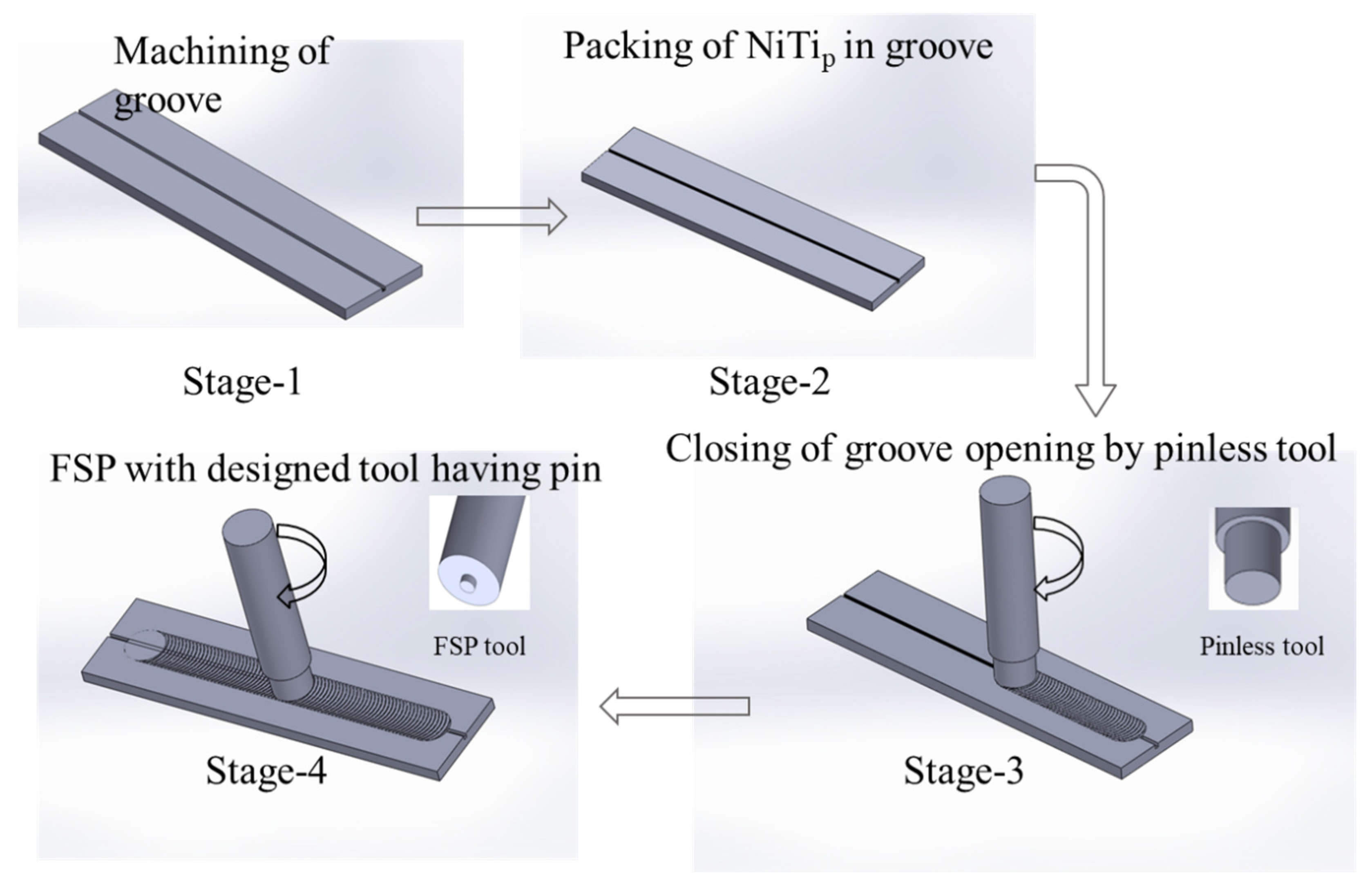
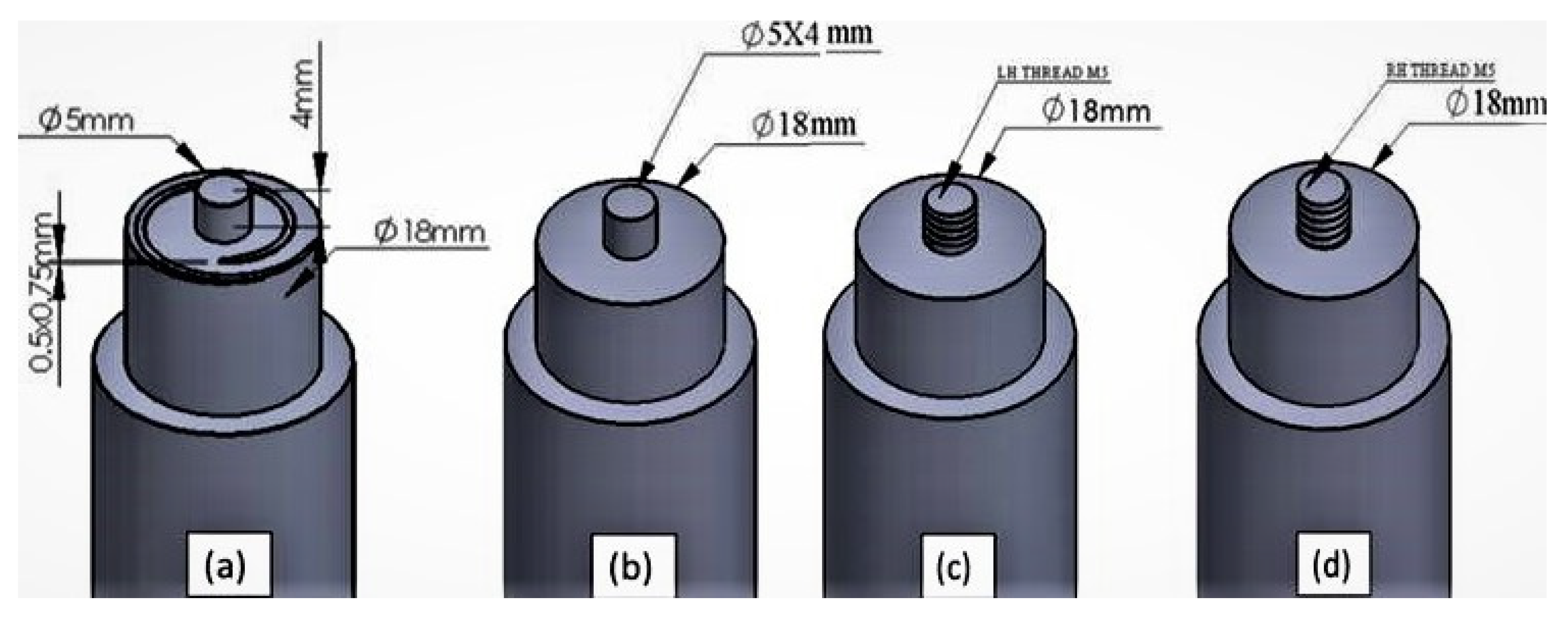
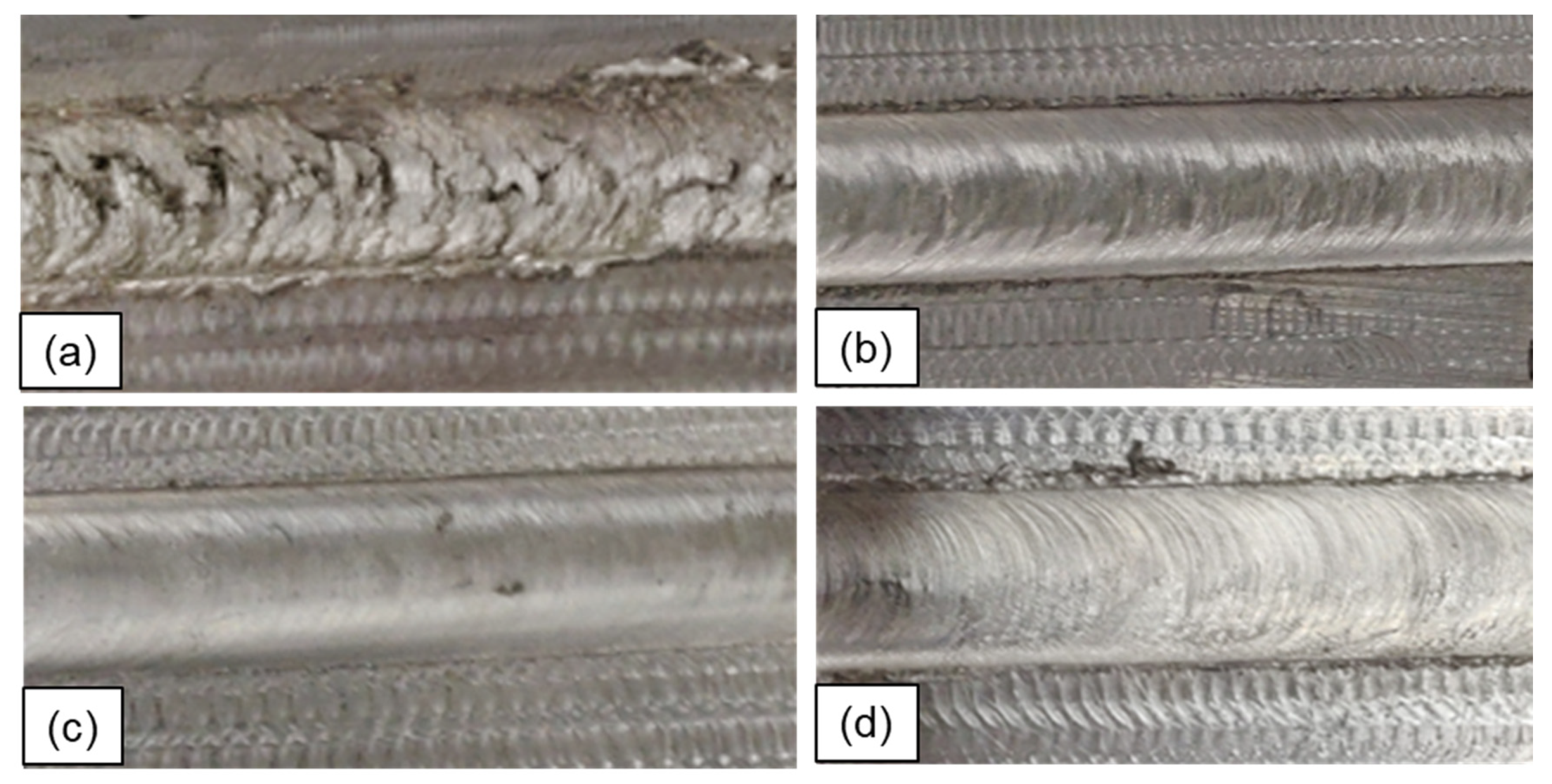
2. Materials and Methods

The elemental concentration of substrate (magnesium) is presented in Table 1. The NiTi SMA with an atomic ratio of 54.9/45.1 was chosen as reinforcement in the particulate form with an average particle size of ≈5 µm. The morphology and particle size of as-received NiTi particles are shown in scanning electron microscopic (SEM) images (Figure 1a,b). Magnesium plates were prepared to a size of 150 mm × 60 mm × 8 mm. The stages involved in the composite fabrication through FSP are shown in a schematic diagram (Figure 2). A deeper slot of 2.5 mm × 3 mm was prepared on the top surface of each plate subsequently filled with reinforcement and enclosed using a plain shouldered tool. The FSP tools were made of high-speed steel. Single-pass FSP was carried out at a fixed setting of a tool tilt angle (2°), tool rotational rate (560 rpm), and traversing speed (100 mm/min). The tool rotational direction was clockwise during the experiment.
Four experiments were carried out using various tool profiles as illustrated in Figure 3 and Table 2. The tool profiles were selected in this study for investigating the material stirring and particle distribution during FSP. The counter or anti-clockwise (ACW) scroll was made on the shoulder for the first experiment (Figure 3a). The left-hand threaded and right-hand threaded tools are abbreviated as LHT and RHT, respectively. The detailed specification of the tool profiles is shown in Figure 3a–d.
The specimens for the microstructural investigation were sectioned across the processing direction from the composite plates and prepared using a standard metallographic procedure, including a rotating disc polisher (QS Metrology, New Delhi, India) up to a grit size of #2500, followed by diamond polishing using a 0.5 μm diamond abrasive paste on a velvet cloth. For the examination of microstructures, the polished coupons were chemically etched with acetic–picral solution [30]. Microstructures were observed using light microscopy (LM) (QS Metrology, New Delhi, India) and SEM (ZEISS EVO MA 15, Jena, Germany). A Vickers microhardness indenter (Mitutoyo, Kawasaki-shi, Kanagawa, Japan) was used to measure the indentation behavior of the composite plates at a load of 1 N for a dwell time of 15 s.

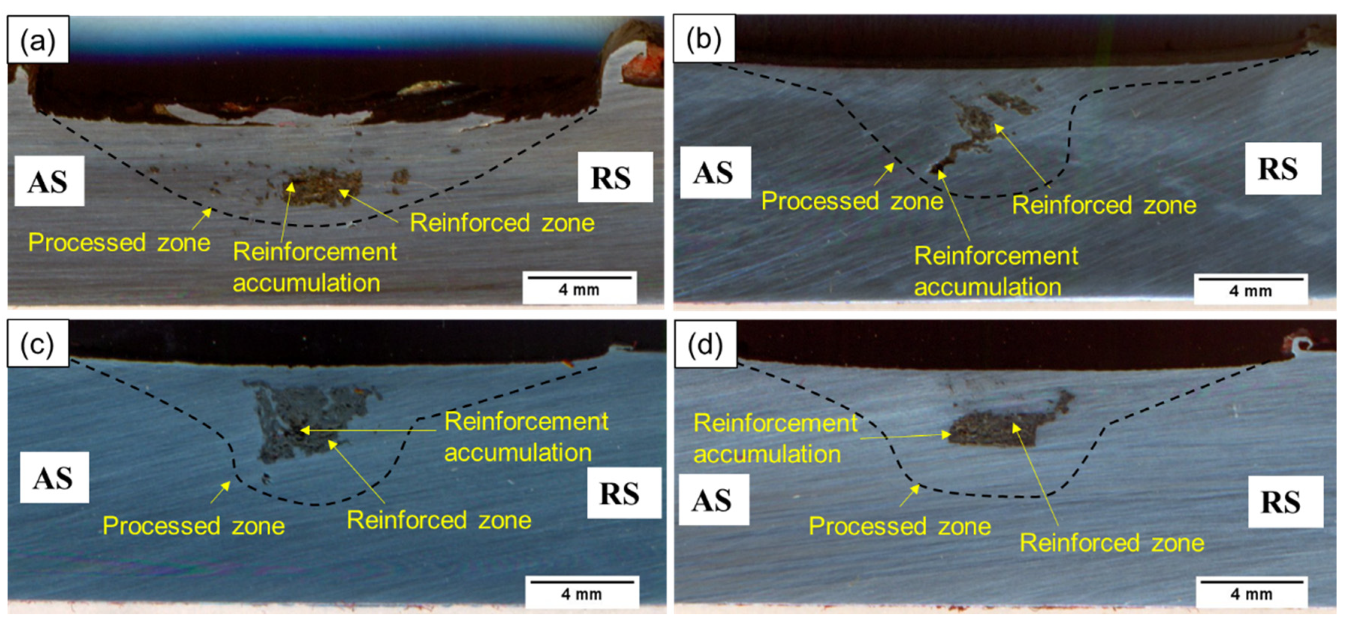
3. Results and Discussion

Friction stir processing was effective in the fabrication of NiTip SMA-reinforced magnesium-based composites. Microstructural characterization together with an indentation test was carried out to identify the role of tool profiles in the fabrication of Mg–NiTip composites. The surface morphology of all the composite plates is presented in Figure 4a–d. Close examination of the surfaces revealed that the composite processed using the ACW tool profile results in a thin layer of material being peeled off from the surface of the unaltered base metal (BM) plate during FSP, leading to flash, material loss, and a very rough top surface (Figure 4a). The processed surfaces of other experiments exhibited good surface quality and are visibly defect-free (Figure 4b–d).
Macrographs of the specimens processed using various tool profiles are shown in Figure 5a–d. No macroscopic defects such as tunnel, cavity, and pores were observed in the macrographs of the fabricated composites. These images show a typical cross-sectional view of processed zones (in the transverse section of composite specimens), where AS and RS indicate the advancing side and the retreating side, respectively. These macrographs reveal the existence of different zones such as a processed zone (PZ), reinforced zone (RZ), and an unaltered base metal (BM). PZ is a zone that has experienced stirring action by the rotating tool. It consists of reinforced and particle-free regions. A minute region of clusters of NiTi particles is also witnessed in the RZ of all the specimens. It is observed from the Figure 5a,b,d that the scrolled shoulder with a plain cylindrical pin, plain shoulder with a plain cylindrical pin, and plain shoulder with a right-hand threaded cylindrical (RHT) cylindrical pin FSP tools could not disperse NiTi particles widely in the magnesium matrix, whereas the composite processed with the plain shoulder with a left-hand threaded cylindrical (LHT) cylindrical pin tool could more effectively disperse the NiTip in a wider zone (Figure 5c).
The flow of plasticized material during friction stir welding/processing (FSW/P) can be better understood via the model of Schneider and Nunes (2004). Important material movement patterns—namely, ring vortex, rigid disc rotational, and uniform translational—may evolve during FSW/P (Figure 6a–c) [31]. The pin thread supports ring vortex flow through the pin/probe threads driving the material up in the outward direction and subsequently inward at the tool shoulder surface, down from the probe threads, and then outward again from the bottom portion of the probe, thus helping mix the reinforcement with the BM matrix (Figure 7a). This type of flow is observed when the directions of the pin thread and tool rotation are opposite. Reversing the tool rotational direction may change the vortex movement direction of the material (Figure 7b) [31,32]. The flow of material during processing is influenced by both the traverse and rotational directions of the tool [33]. Chances for the formation of defects such as the porosity and poor bonding near the lower part are high when processing with an RHT pin tool due to opposite vortex movement direction [32]. In the present investigation, no such porosity was observed with the RHT pin tool. It is clear that the ring vortex flow has been experienced by the material during processing with an LHT pin tool, while the tool rotates in the clockwise direction and could contribute to the better distribution of NiTip.
Higher magnification LM images of the clustered zone of the processed specimens are shown in Figure 8a–d. In the clustered regions, reinforcement shows poor bonding with the metal matrix, as the reinforcement was washed out during etching, giving a dark-pit type appearance. The LM images of the NiTip-dispersed region near the AS interface/transition are shown in Figure 9a–d. In these regions, the NiTip shows intimate bonding with the magnesium matrix.
Typical scanning electron micrographs (SEM) of specimen 3 processed with an LHT pin is shown in Figure 10a,b. Regions of clustering and the dispersion of NiTip are displayed in Figure 10a,b, respectively. The interface between NiTip and the magnesium matrix is clean. Furthermore, one of the most favorable observations is that there are no signs of diffusion and interfacial product around the NiTi particles in the magnesium matrix as a consequence of FSP. Thus, one of the greatest challenges in the processing of NiTi metal matrix composites, i.e., the control of interfacial reactions to form Mg2Ni, Mg–Ti–O, Mg–O, etc., in the case of powder and liquid metallurgy practices due to the high activity of NiTi at the processing temperature and time, can be effectively avoided. The reaction products are brittle IMCs and are harmful for interfacial bonding strength [17,20,34]. Moreover, as the NiTip has special SME characteristics, the presence of interface reactions could also spoil this useful property. The highest temperature and time, which evolve during processing in FSP, is significantly lower as compared with liquid and powder metallurgy practices. During the FSP of the Al or Mg metal matrix, the temperature of the plasticized material is about 400 °C in the stir zone, and the thermal cycle is very short (a few seconds), which significantly lowers the likelihood of interfacial/diffusion reactions; hence, no diffusion/interfacial products are formed during NiTip-reinforced composite fabrication [25,26,27,28,29].
The microhardness distribution across the fabricated composites is shown in Figure 11. It was measured 2 mm below the top surface, along the width from AS to RS of the processed region. The notable enhancement in hardness of all the specimens was observed in the RZ region in comparison with the BM hardness, which was measured as 35 ± 5 HV. The average values of microhardness in the PZ was observed to be about 59, 45, 97, and 106 HV for specimens 1, 2, 3, and 4, respectively. The peak hardness of 385 HV was observed in specimen number 4 at the middle of the PZ. A close examination of this specimen revealed the localized accumulation of reinforcement NiTip, which leads to a spike in the peak hardness value in the indented region. A relatively more homogeneous distribution of hardness values was observed in specimen number 3, which was processed with an LHT cylindrical pin tool.
Zheng et al. [35] compared the microhardness of NZ30K magnesium alloy in unprocessed and FSPed conditions. An improvement of ~26% was observed at the center of the stir zone of the FSPed sample as compared to the unprocessed region. The improvement in the microhardness of the FSPed sample was attributed to the significant grain refinement during FSP. In the present investigation, a careful observation on the indentation values and particle distribution indicates that the processed region without reinforcement shows a ~30–55% improvement in microhardness values, and a more than three-fold increase in the microhardness value was observed in the composited region due to the presence of NiTip reinforcement as compared to BM.
During FSP, heat is generated due to friction between the FSP tool and matrix material, which plasticizes the material underneath, and the rotating tool produces plastic deformation and stirring of the BM along with reinforcement. As the tool starts its travel, the material ahead of the tool pin is deposited behind, which fills the void created by the advancing tool pin. The FSP causes intense or severe plastic deformation, which mixes the NiTip with the matrix material and refines the grains due to the occurrence of dynamic recrystallization (DRX) [36,37]. During continued stirring, the NiTip further refine the grains successively by impeding the growth of grains via Zener pinning [38]. In the phenomenon of Zener pinning, the incorporated reinforcement particles in the matrix act as obstacles to the movement of grain boundaries. The difference in the coefficients of thermal expansion (CTE) of the deformed matrix and NiTip reinforcement results in an increase in dislocations and further increases the hardness of composites [39,40,41]. All these simultaneous occurring phenomena increase the microhardness of composites. Apart from the above discussed mechanisms, the higher hardness of the reinforcement particles also contributes to the higher hardness of composites [38,39,42].
It should be noted that the functional benefits of NiTip reinforcement cannot be reaped until the distribution of these particles in the matrix is proper and also in a desired volume fraction. Stirring with a uniform distribution of reinforcement particles within Mg is challenging, and this study represents some preliminary attempts of producing acceptable surface composites from NiTip in pure Mg affected by the tool profiles. More studies in this aspect, including the effect of processing speed and rotational rate, are needed to optimize the FSP so as to produce the high-performance composites for functional advantages.

4. Conclusions

The Mg/NiTip composites were developed via the FSP technique and investigated for their microstructural aspects. The present study demonstrated that the tool profile greatly affected the microstructure in the Mg/NiTip composite fabrication. The results obtained could be concluded as follows:
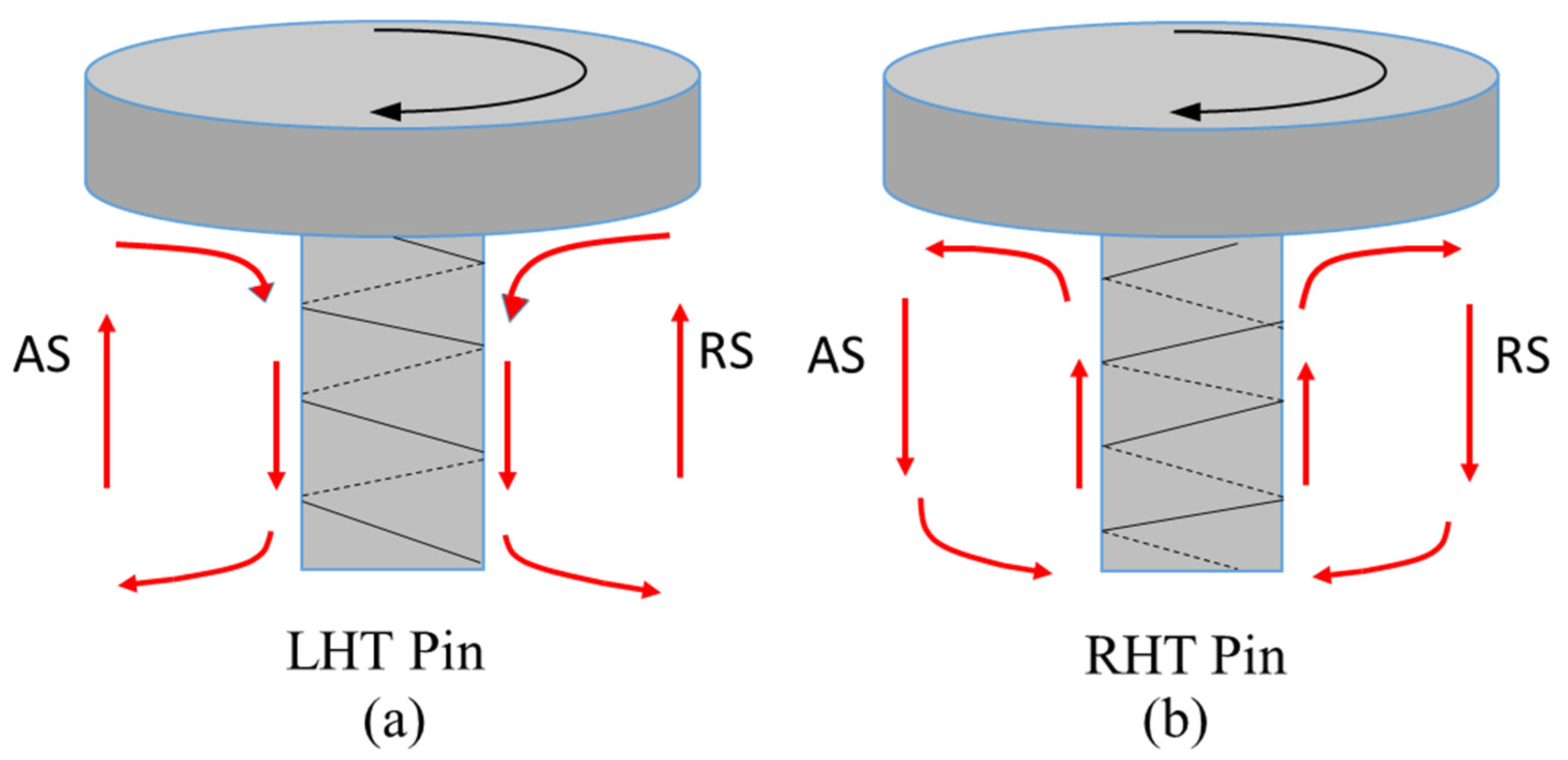
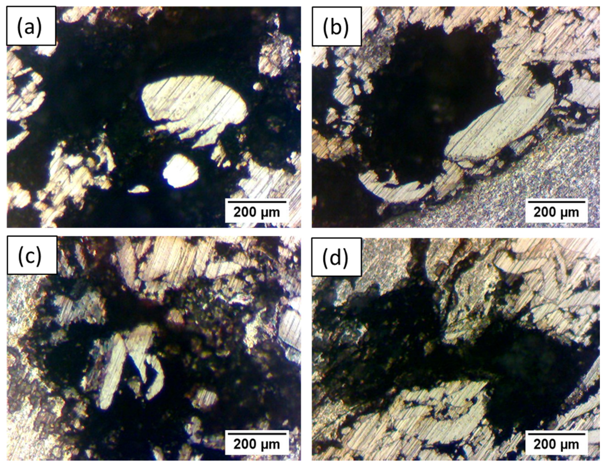
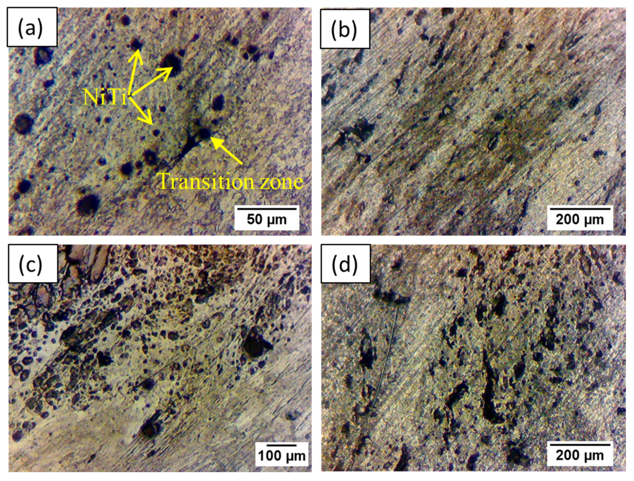
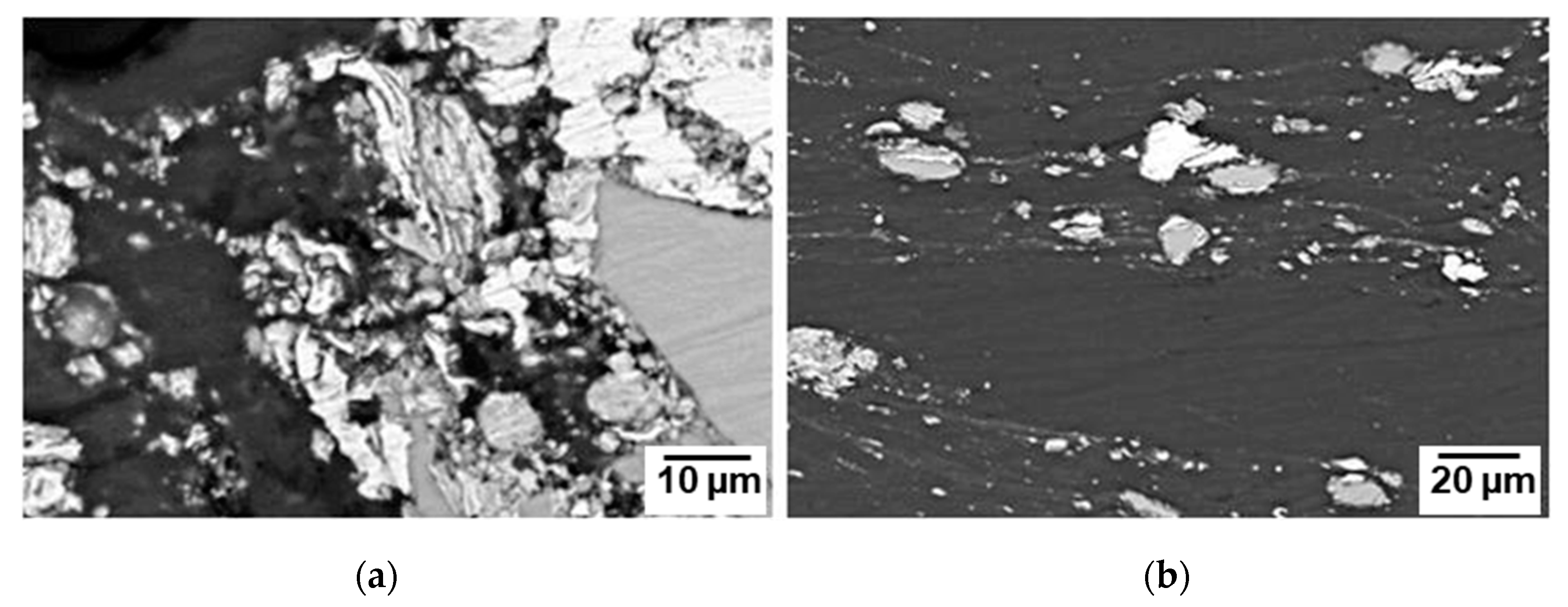
  • A wider distribution of NiTip was attained with a left-hand threaded (LHT) cylindrical pin tool among the four tool profiles. SEM observations indicated good bonding of NiTip with the magnesium matrix.
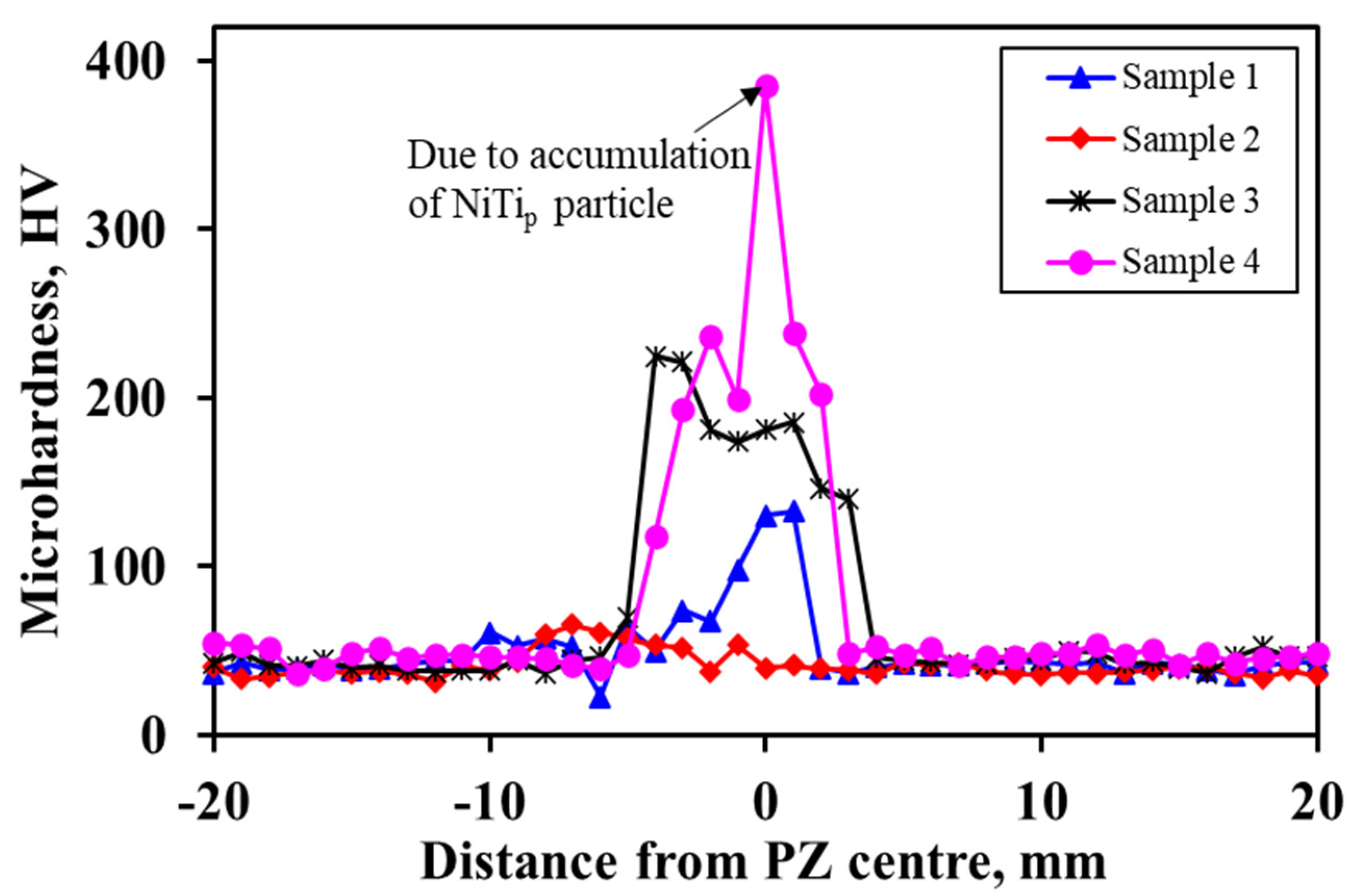
  • The incorporation of NiTip resulted in a significant increase in the microhardness of the fabricated composites due to a variety of hardening mechanisms presented.
  • The LHT pin tool processed composite showed a more uniform hardness profile across the processed zone, with an average microhardness value of 97 HV.

Author Contributions

Conceptualization, N.G. and A.N.S.; methodology, N.G., S.M., D.S.; software/plots, S.M.A.K.M.; formal analysis, N.G. and A.N.S.; investigation, N.G., H.N. and S.M.; resources, N.G., D.S. and A.N.S.; data curation, N.G., H.N., and S.M.A.K.M.; writing—original draft preparation, N.G., A.N.S.; writing—review and editing, N.G., S.M.A.K.M., A.N.S. and D.L.C.; visualization, N.G.; supervision, N.G.; project administration, N.G. and A.N.S.; funding acquisition, N.G. All authors have read and agreed to the published version of the manuscript.

Funding

This research was funded by A.P.J. Abdul Kalam Technical University (AKTU), Lucknow, India under CRIP TEQIP-III, grant number AKTU/Dean-PGSR/2019/CRIP/34.

Conflicts of Interest

The authors declare no conflict of interest.

References

  1. Mahmoudi, M.; Tapia, G.; Franco, B.; Ma, J.; Arroyave, R.; Karaman, I.; Elwany, A. On the printability and transformation behavior of nickel-titanium shape memory alloys fabricated using laser powder-bed fusion additive manufacturing. J. Manuf. Process. 2018, 35, 672–680. [Google Scholar] [CrossRef]
  2. Gangil, N.; Siddiquee, A.N.; Maheshwari, S. Towards applications, processing and advancements in shape memory alloy and its composites. J. Manuf. Process. 2020, 59, 205–222. [Google Scholar] [CrossRef]
  3. Chen, X.; Liu, K.; Guo, W.; Gangil, N.; Siddiquee, A.N.; Konovalov, S. The fabrication of NiTi shape memory alloy by selective laser melting: A review. Rapid Prototyp. J. 2019, 25, 1421–1432. [Google Scholar] [CrossRef]
  4. Vollmer, M.; Arold, T.; Kriegel, M.J.; Klemm, V.; Degener, S.; Freudenberger, J.; Niendorf, T. Promoting abnormal grain growth in Fe-based shape memory alloys through compositional adjustments. Nat. Commun. 2019, 10, 1–10. [Google Scholar] [CrossRef] [Green Version]
  5. Ni, D.R.; Ma, Z.Y. Shape memory alloy-reinforced metal-matrix composites: A review. Acta Metall. Sin. Engl. Lett. 2014, 27, 739–761. [Google Scholar] [CrossRef]
  6. Wen, C.; Yu, X.; Zeng, W.; Zhao, S.; Wang, L.; Wan, G.; Huang, S.; Grover, H.; Chen, Z. Mechanical behaviors and biomedical applications of shape memory materials: A review. AIMS Mater. Sci. 2018, 5, 559–590. [Google Scholar] [CrossRef]
  7. Worch, J.C.; Andrew, C.W.; Jiayi, Y.; Maria, C.A.; Thomas, R.W.; Robert, T.R.H.; Rachel, K.O.; Matthew, L.B.; Andrew, P.D. Elastomeric polyamide biomaterials with stereochemically tuneable mechanical properties and shape memory. Nat. Commun. 2020, 11, 1–11. [Google Scholar] [CrossRef]
  8. Zhao, S.; Teng, J.; Wang, Z.; Sun, X.; Yang, B. Investigation on the mechanical properties of SMA/GF/epoxy hybrid composite laminates: Flexural, impact, and interfacial shear performance. Materials 2018, 11, 246. [Google Scholar] [CrossRef] [Green Version]
  9. Quade, D.J.; Jana, S.C.; Morscher, G.N.; Kanaan, M. The effect of thin film adhesives on mode I interlaminar fracture toughness in carbon fibre composites with shape memory alloy inserts. Eng. Fract. Mech. 2019, 206, 131–146. [Google Scholar] [CrossRef] [Green Version]
  10. Angioni, S.L.; Meo, M.; Foreman, A. Impact damage resistance and damage suppression properties of shape memory alloys in hybrid composites-A review. Smart Mater. Struct. 2010, 20, 013001. [Google Scholar] [CrossRef]
  11. Wei, Z.G.; Tang, C.Y.; Lee, W.B. Design and fabrication of intelligent composites based on shape memory alloys. J. Mater. Process. Technol. 1997, 69, 68–74. [Google Scholar] [CrossRef]
  12. Wakeel, S.; Manakari, V.; Parande, G.; Kujur, M.S.; Khan, A.A.; Gupta, M. Synthesis and mechanical response of NiTi SMA nanoparticle reinforced mg composites synthesized through microwave sintering process. Mater. Today Proc. 2018, 5, 28203–28210. [Google Scholar] [CrossRef]
  13. Liu, Y.; Al-Matar, B.; Newaz, G. An investigation on the interface in a NiTi short-fiber-reinforced 6061 aluminum composite by transmission electron microscope. Metall. Mater. Trans. A 2008, 39A, 2749–2759. [Google Scholar] [CrossRef]
  14. Hahnlen, R.; Dapino, M.J. NiTi-Al interface strength in ultrasonic additive manufacturing composites. Compos. Part B 2014, 59, 101–108. [Google Scholar] [CrossRef]
  15. Wang, Z.; Dong, P.; Wang, W.; Yan, Z.; Ding, M. Interface formation of TiNif/Al composites fabricated by spark plasma sintering. J. Alloys Compd. 2017, 726, 507–513. [Google Scholar] [CrossRef]
  16. Guo, W.; Kato, H.; Lu, S.; Wu, S. Porous NiTi particle dispersed Mg-Zn-Ca bulk metallic glass matrix composites. Materials 2018, 11, 1959. [Google Scholar] [CrossRef] [PubMed] [Green Version]
  17. Parande, G.; Manakari, V.; Wakeel, S.; Kujur, M.S.; Gupta, M. Enhancing mechanical response of monolithic magnesium using nano-NiTi (Nitinol) particles. Metals 2018, 8, 1014. [Google Scholar] [CrossRef] [Green Version]
  18. Hu, J.; Wu, G.; Zhang, Q.; Kang, P.; Liu, Y. Microstructure of multilayer interface in an Al matrix composite reinforced by TiNi fiber. Micron 2014, 64, 57–65. [Google Scholar] [CrossRef]
  19. Guo, W.; Wada, T.; Kato, H. Work-hardenable Mg-based bulk metallic glass matrix composites reinforced by ex-situ porous shape-memory-alloy particles. Mater. Lett. 2016, 183, 454–458. [Google Scholar] [CrossRef]
  20. Li, X.; Jiang, F.; Wang, Z.; Guo, C.; Wang, J.; Niu, Z.; Chang, Y. Interfacial characteristics and normal mechanical strength of a NiTi shape memory alloy fiber reinforced Mg3AlZn (SMAFR-AZ31) composite sheet. Mater. Sci. Eng. A 2019, 765, 138283. [Google Scholar] [CrossRef]
  21. Wang, E.; Tian, Y.; Wang, Z.; Jiao, F.; Guo, C.; Jiang, F. A study of shape memory alloy NiTi fiber/plate reinforced (SMAFR/SMAPR) Ti-Al laminated composites. J. Alloys Compd. 2017, 696, 1059–1066. [Google Scholar] [CrossRef]
  22. Tun, K.; Zhang, Y.; Parande, G.; Manakari, V.; Gupta, M. Enhancing the hardness and compressive response of magnesium using complex composition alloy reinforcement. Metals 2018, 8, 276. [Google Scholar] [CrossRef] [Green Version]
  23. Barta, N.E.; Karaman, I. Embedded magnetic shape memory sensory particles in lightweight composites for crack detection. Mater. Sci. Eng. A 2019, 751, 201–213. [Google Scholar] [CrossRef]
  24. Kong, C.Y.; Soar, R.C.; Dickens, P.M. Ultrasonic consolidation for embedding SMA fibres within aluminum matrices. Compos. Struct. 2004, 66, 421–427. [Google Scholar] [CrossRef]
  25. Dixit, M.; Newkirk, J.W.; Mishra, R.S. Properties of friction stir-processed Al 1100-NiTi composite. Scr. Mater. 2007, 56, 541–544. [Google Scholar] [CrossRef]
  26. Ni, D.R.; Wang, J.J.; Zhou, Z.N.; Ma, Z.Y. Fabrication and mechanical properties of bulk NiTip/Al composites prepared by friction stir processing. J. Alloys Compd. 2014, 586, 368–374. [Google Scholar] [CrossRef]
  27. Oliveira, J.P.; Duarte, J.F.; Inacio, P.; Schell, N.; Miranda, R.M.; Santos, T.G. Production of Al/NiTi composites by friction stir welding assisted by electrical current. Mater. Des. 2017, 113, 311–318. [Google Scholar] [CrossRef] [Green Version]
  28. Huang, G.Q.; Yan, Y.F.; Wu, J.; Shen, Y.F.; Gerlich, A.P. Microstructure and mechanical properties of fine-grained aluminum matrix composite reinforced with Nitinol shape memory alloy particulates produced by underwater friction stir processing. J. Alloys Compd. 2019, 786, 257–271. [Google Scholar] [CrossRef]
  29. Zhao, L.; Ding, L.; Soete, J.; Idrissi, H.; Kerckhofs, G.; Simar, A. Fostering crack deviation via local internal stresses in Al/NiTi composites and its correlation with fracture toughness. Compos. Part A 2019, 126, 105617. [Google Scholar] [CrossRef]
  30. Gangil, N.; Nagar, H.; Kumar, R.; Singh, D. Shape memory alloy reinforced magnesium matrix composite fabricated via friction stir processing. Mater. Today Proc. 2020. [Google Scholar] [CrossRef]
  31. Schneider, J.A.; Nunes, A.C., Jr. Characterization of plastic flow and resulting microstructures in a friction stir weld. Metall. Mater. Trans. B 2004, 35B, 777–783. [Google Scholar] [CrossRef]
  32. Chowdhury, S.M.; Chen, D.L.; Bhole, S.D.; Cao, X. Effect of pin tool thread orientation on fatigue strength of friction stir welded AZ31B-H24 Mg butt joints. Procedia Eng. 2010, 2, 825–833. [Google Scholar] [CrossRef] [Green Version]
  33. Rai, R.; De, A.; Bhadeshia, H.K.D.H.; DebRoy, T. Review: Friction stir welding tools. Sci. Technol. Weld. Join. 2011, 16, 325–342. [Google Scholar] [CrossRef]
  34. Mizuuchi, K.; Inoue, K.; Hamada, K.; Sugioka, M.; Itami, M.; Fukusumi, M.; Kawahara, M. Processing of TiNi SMA fiber reinforced AZ31 Mg alloy matrix composite by pulsed current hot pressing. Mater. Sci. Eng. A 2004, 367, 343–349. [Google Scholar] [CrossRef]
  35. Zheng, F.Y.; Wu, Y.J.; Peng, L.M.; Li, X.W.; Fu, P.H.; Ding, W.J. Microstructures and mechanical properties of friction stir processed Mg-2.0Nd-0.3Zn-1.0Zr magnesium alloy. J. Magnes. Alloys 2013, 1, 122–127. [Google Scholar] [CrossRef] [Green Version]
  36. Gangil, N.; Maheshwari, S.; Siddiquee, A.N. Influence of tool pin and shoulder geometries on microstructure of friction stir processed AA6063/SiC composites. Mech. Ind. 2018, 19, 211. [Google Scholar] [CrossRef]
  37. Gangil, N.; Maheshwari, S.; Nasr, E.A.; El-Tamimi, A.M.; El-Meligy, M.A.; Siddiquee, A.N. Another approach to characterize particle distribution during surface composite fabrication using friction stir processing. Metals 2018, 8, 568. [Google Scholar] [CrossRef] [Green Version]
  38. Gangil, N.; Siddiquee, A.N.; Maheshwari, S.; AL-Ahmari, A.M.; Abidi, M.H. State of the art of ex-situ aluminum matrix composite fabrication through friction stir processing. Arch. Metall. Mater. 2018, 63, 719–738. [Google Scholar]
  39. Qu, J.; Xu, H.; Feng, Z.; Frederick, D.A.; An, L.; Heinrich, H. Improving the tribological characteristics of aluminum 6061 alloy by surface compositing with sub-micro-size ceramic particles via friction stir processing. Wear 2011, 271, 1940–1945. [Google Scholar] [CrossRef]
  40. Zhang, Z.; Chen, D.L. Consideration of Orowan strengthening effect in particulate-reinforced metal matrix nanocomposites: A model for predicting their yield strength. Scr. Mater. 2006, 54, 1321–1326. [Google Scholar] [CrossRef]
  41. Zhang, Z.; Chen, D.L. Contribution of Orowan strengthening effect in particulate-reinforced metal matrix nanocomposites. Mater. Sci. Eng. A 2008, 483, 148–152. [Google Scholar] [CrossRef]
  42. Kurt, A.; Uygur, A.; Cete, E. Surface modification of aluminum by friction stir processing. J. Mater. Process. Technol. 2011, 211, 313–317. [Google Scholar] [CrossRef]
Figure 1. (a,b) Scanning electron microscope (SEM) images of Nitinol particulate (NiTip) used in the present study.
Metals 10 01425 g001
Figure 2. Schematic diagram showing the stages involved in the composite fabrication via friction stir processing (FSP).
Metals 10 01425 g002
Figure 3. (ad) Models of tool profiles.
Metals 10 01425 g003
Figure 4. Top surface of the plates processed using (a) anti-clockwise (ACW) scroll shoulder having a plain cylindrical pin, (b) plain shoulder having a plain cylindrical pin, (c) plain shoulder having a left-hand threaded cylindrical (LHT) pin, and (d) plain shoulder having a right-hand threaded cylindrical (RHT) pin.
Metals 10 01425 g004
Figure 5. Macro images of the transverse section of processed plates (a) specimen 1, (b) specimen 2, (c) specimen 3, and (d) specimen 4.
Metals 10 01425 g005
Figure 6. Material flow pattern during friction stir welding/processing (FSW/P) showing (a) ring vortex, (b) rigid disc rotational, and (c) uniform translational flow fields.
Metals 10 01425 g006
Figure 7. Schematic diagram showing (a) an LHT pin tool and (b) RHT pin tool, depicting the dependence of ring vortex flow direction on the pin thread type.
Metals 10 01425 g007
Figure 8. Light microscopy (LM) images showing the clustered regions of (a) specimen 1, (b) specimen 2, (c) specimen 3, and (d) specimen 4.
Metals 10 01425 g008
Figure 9. LM images showing the composited regions of (a) specimen 1, (b) specimen 2, (c) specimen 3, and (d) specimen 4.
Metals 10 01425 g009
Figure 10. SEM images of cross-section of specimen 3, showing (a) a clustered region and (b) a reinforced region.
Metals 10 01425 g010
Figure 11. Microhardness profile measured across the cross-section of the fabricated composites.
Metals 10 01425 g011
Table 1. Elemental composition of pure magnesium (wt %).
ElementCuPbFeAlNiCdZnMnSiMg
wt %0.0250.0020.0040.0560.002<0.0010.0050.0010.005Remainder
Table 2. Tool profiles designed for the present study.
Sample NumberShoulder ProfilePin Profile
1ACW scrollPlain cylindrical
2PlainPlain cylindrical
3PlainLeft-hand threaded cylindrical (LHT)
4PlainRight-hand threaded cylindrical (RHT)
Publisher’s Note: MDPI stays neutral with regard to jurisdictional claims in published maps and institutional affiliations.

