

Torque Ripple Suppression of Switched Reluctance Motor with Reference Torque Online Correction

1
School of Electronic and Automation, Guilin University of Electronic Technology, Guilin 541004, China
2
School of Electronic Information and Automation, Guilin University of Aerospace Technology, Guilin 541004, China
*
Author to whom correspondence should be addressed.
Machines 2023, 11(2), 179; https://doi.org/10.3390/machines11020179
Submission received: 26 December 2022
/
Revised: 12 January 2023
/
Accepted: 17 January 2023
/
Published: 28 January 2023
(This article belongs to the Topic Advanced Electrical Machines and Drives Technologies)
Abstract
:High torque ripple dramatically affects the switched reluctance motor (SRM) application. To reduce the torque ripple, a reference torque neural network (RTNN) is proposed to adjust the reference torque online. Firstly, the RTNN is built on the torque sharing function (TSF) method. Furthermore, the RTNN is designed as a single-input and -output network. As the periodic relationship between the torque ripple and the rotor angle, the rotor angle constitutes the central node parameter of the implicit function in RTNN. Therefore, one-step adjustment of the RTNN can perform well at restraining reference torque. Lastly, the torque error is used to adjust the parameters of RTNN to reduce the torque ripple. In the MATLAB environment, through the simulation comparison with fuzzy torque and PD current compensation method, the effectiveness of RTNN at torque ripple suppression is proven with different loads and speeds.
1. Introduction
The switched reluctance motor (SRM) has the advantages of high power density, wide speed range, high reliability, and low manufacturing cost. In addition, due to the simple and robust structure, SRMs have high reliability and can operate in harsh environments [1,2,3]. However, due to its unique doubly salient structure, a large torque ripple will occur, which can be attributed to the nonlinear relationship between torque and current in the operation process [4,5].
Current control-based methods to reduce torque ripple mainly include current mode predictive control (MPC), torque sharing function (TSF), instant torque compensation, and current injection method.
The voltage prediction can be calculated by MPC via the micro-step method, according to the rotor voltage and flux equation [6]. Firstly, the cost function of minimum flux is designed following the flux model. Then, the MPC algorithm is employed for flux prediction and control [7]. On the basis of this idea, the predictive current control method can be further utilized [8]. An unconstrained MPC for current control can cope with the measurement noise and uncertainties within the machine inductance profile [9]. Nonetheless, the MPC Model recommendations can take a long time depending on the precise mathematical model of the SRM [10].
The TSF method has the advantage of a simple structure. The torque ripple and copper loss can reach their lowest levels by adding coefficients to the transient phase and using a genetic algorithm for optimization [11]. The torque sharing function can be further optimized according to the reference current of the torque distribution at different angles [12]. The above three methods require offline training. In comparison, the online method can adjust reference current without training. The iterative optimization method is divided into the outer loop and inner loop, the outer loop optimization of the turn-off angle to reduce copper loss, the inner loop optimization of torque ripple, the introduction of feedback torque, and the optimization of the turn-on angle [13]. The inductance derivatives under different rotor angles and phase currents are calculated through finite element analysis, and the partial derivatives can be used to calculate the given current [14]. However, this method needs to adapt better to load changes, and improvement in the accuracy of the rotor angle is required [15]. Therefore, the accuracy of rotor angle needs to be considered [16].
To reduce torque ripple, instant torque can be employed as compensation for current. During the commutation interval, the difference between the reference and instant torque can be used to obtain the modified reference torque, which will finally translate to the reference current [17]. As the torque ripple in the commutation section is more serious, the feedback torque is used to reduce the torque ripple in the commutation section, and the effect is more pronounced [18]. The Lagrangian multiplier method can also be employed to minimize current ripple and optimize the copper loss and torque ripple [19]. As the flux change rate influences the speed and output torque, the torque error is used to adjust the reference torque of the first and second half of the transition section [20]. Changing the supply voltage can also reduce the torque ripple by avoiding torque generation in the negative torque region [21]. At the same time, the genetic algorithm and least square method can also reduce torque ripple by optimizing the opening angle and transition angle [22]. The error between the reference and the instant torque constitutes a fuzzy set to generate a reference current insensitive to rotor angles [23]. According to the current voltage and speed, the maximum output torque capacity of the current phase is calculated, and the other phase compensates for the defective part to obtain the phase reference torque of the commutation [24]. Torque error fuzzy processing, resulting in compensation current, can also reduce torque ripple [25].
A proper compensation current is essential in the current injection method. The torque error can be used as a ratio to inject into the present current, and repeat the process in the iterative learning process to obtain a proper compensation current [26]. The DC and first and second current harmonics mainly contribute to the average torque. In comparison, the fourth and fifth current harmonics significantly influence the torque ripple, but contribute much lower to the average torque [27]. Therefore, finite element analysis and current profiling adjustment can effectively reduce torque ripple through torque error [28]. To obtain the inductance value and change rate in the coefficient of torque formula, injecting high-frequency voltage is feasible [29]. The coefficient of the relationship between compensation current and torque error is complex. Reference torque, instant torque deviation, and rotor angle are input into the fuzzy controller to obtain compensation current [30]. The feed-forward plus torque compensation can reduce the dynamic response time and improve the steady-state accuracy of electromagnetic torque [31]. The fuzzy compensator adjusts the torque error, and the torque ripple can also be reduced by compensating the result to the reference torque [32].
The speed controller can generate the reference torque in TSF, but there is always a difference between the reference and instant torque. This difference is attributed to the reference current generated by the TSF, which is not the actual current required, resulting in a large torque ripple.
Based on parameter adjustment learning, neural networks can be employed for model identification and control [33]. The robustness of the system to speed control can be enhanced by introducing a neural network into the sensorless speed [34]. Similarly, the optimal control parameters of the SRM can be calculated using a dynamic SRM model, and the parameter curve can be fitted by a neural network [35]. A nonlinear flux linkage model can be trained by constructing a network of two hidden layers with two-dimensional positions, current inputs, and flux linkage output [36]. Applying the improved generalized regression neural network optimized by the fruit fly optimization algorithm to the modeling of the SRM can further improve the effectiveness and superiority of the neural network [37]. A neural network based on learning error pretreatment for flux linkage control of the SRM can effectively reduce torque ripple and has excellent repeatability [38].
Based on the above analysis, a reference torque neural network (RTNN) is herein designed to adjust the reference torque online to reduce torque ripple. The contribution of this manuscript is
(1) A RTNN is designed to correct the reference torque, employing the instant torque as feedback and rotor angle as the center of the neural network.
(2) The implicit function in the RTNN is constructed according to the total current’s characteristics. Compared with the fuzzy and proportional derivative (PD) compensation, the RTNN can compensate the current more effectively, reducing the torque ripple more noticeably.
(3) The RTNN is designed for online learning and one-step adjustment, avoiding offline training.
The rest of this article is organized as follows. In Section 2, the principle of reference torque generating is introduced. Section 3 proposes the strategy of reference torque modified by RTNN. In Section 4, the performances of the proposed scheme are evaluated via simulations under different operating conditions. Finally, Section 5 concludes this article.
2. Reference Torque Generation
SRM has a double salient pole structure, its operation follows the principle of minimum reluctance, and to obtain higher energy conversion efficiency, SRM works in the magnetic saturation region, which makes the nonlinear problem of the motor more serious.
The electromagnetic torque of SRM, which is related to current and rotor angle, can be calculated from the partial derivative of the co-energy to the rotor angle, as follows:
where is the co-energy. As the effect of magnetic saturation is very low, neglecting the saturated nature, we apply the formula as
By substituting Equation (2) into Equation (1), we obtain
where i is phase current, L is phase inductance, and is rotor angle.
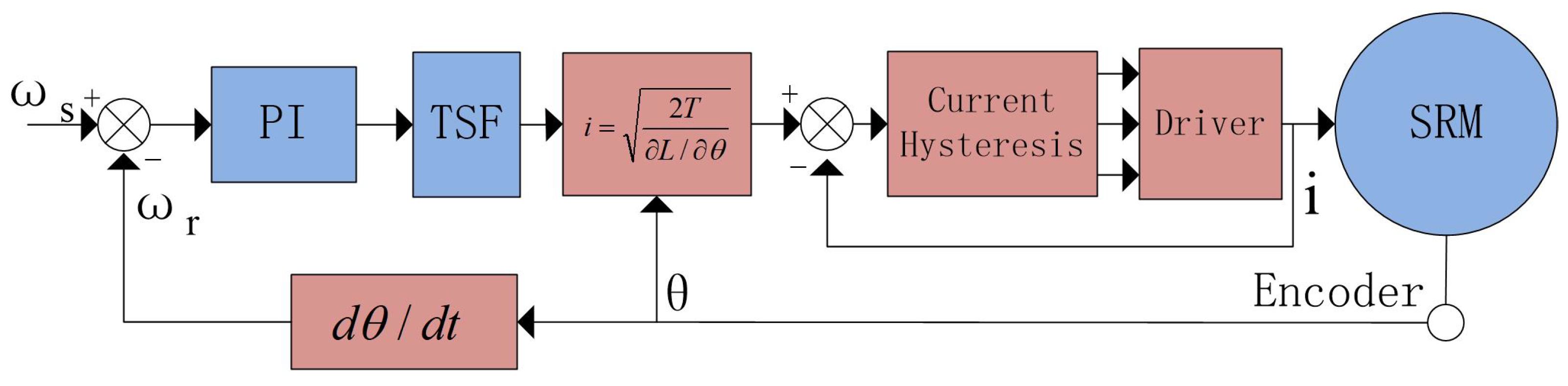
The torque distribution formula is distributed to each phase as the reference torque is obtained, as Figure 1 shows. The typical TSF includes linear TSF, sinusoidal TSF, and cubic TSF. Among them, the transition section in cubic TSF is more stable. Therefore, the cubic TSF is employed, and its distribution function is presented as Equation (4).
where is the on angle, is the off angle, is the overlap angle, and is the period.
The distributed torque is converted into current by Equation (5).
The reference torque of each phase is then converted into the reference current, and the given current is compared with the feedback current to control the drive circuit on and off angle, thereby realizing the motor control. In the linearized TSF control method, , is treated as a constant value because its value varies negligibly compared to the value of the current. Current can be calculated by Equation (5). This allows the SRM to operate under different conditions. However, is not a constant value, its value changes with instant current and rotor angle. The improper selection of the inductive derivative will lead to a detrimental reference current, resulting in torque ripple.
3. Reference Torque Modified by RTNN
3.1. Relationship between Reference Torque and Instant Torque
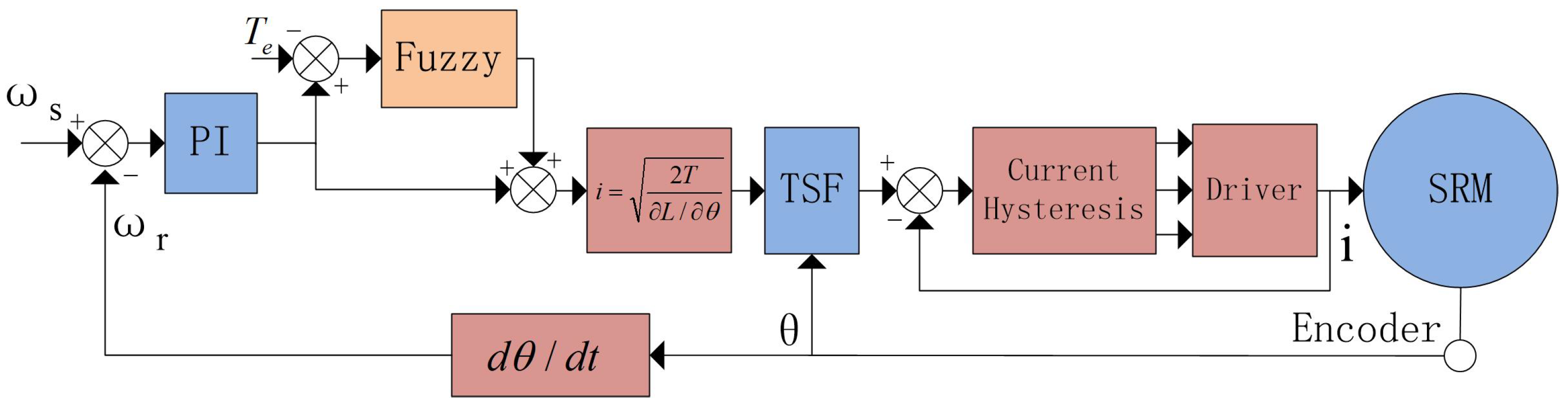
It is a standard method to reduce torque ripple using the difference between instantaneous torque and reference torque, using the difference to compensate for the reference torque. However, as the compensation basis needs to be clarified, the fuzzy method must work with an unclear model [32].
Calculate the difference between the instantaneous and reference torque and form the fuzzy torque compensation according to the difference and the change in the difference. The resulting system control structure is shown in Figure 2. The designed fuzzy controller combines the artificial experience value to provide compensation torque.
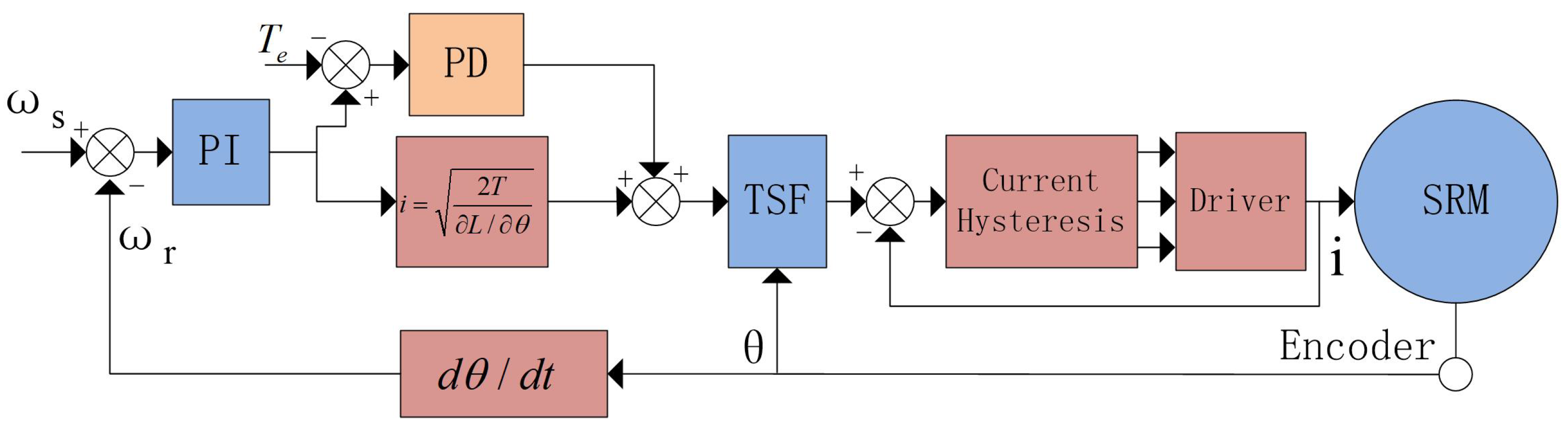
Since the final control object is current, the method of transforming torque error to the reference current is designed. The instantaneous torque is introduced to compensate for the reference current in advance, and the PD controller is used to compensate [31]. The structure designed is shown in Figure 3.
The PD algorithm can be classified as the model-free control method. The transformation from the torque error to the compensation current does not need any SRM model, but its parameter adjustment consumes lots of time. Therefore, whether the parameter selection is reasonable or not has a significant influence on the compensation effect.
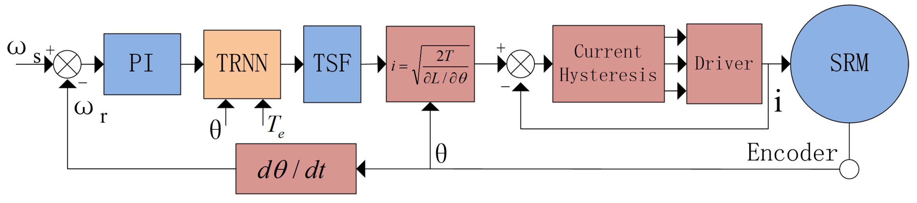
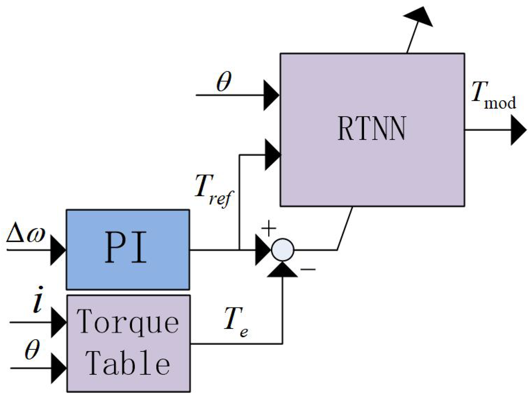
This paper considers the compensation method of parameter self-adjustment and self-learning. Due to the fact that the neural network has excellent self-learning ability, the neural network is introduced to learn the compensation amount according to the present rotor angle and torque error. The structure is shown in Figure 4.
The RTNN is placed following the PI speed controller, which adjusts the reference torque slightly according to the present rotor angle and torque error. The subsequent process is the same as the conventional TSF method to maintain the simplicity and stability of the control structure.
In the TSF method, the reference torque is calculated according to the mechanical equation of the motor. Nonetheless, there should always be a difference between the reference and feedback torque.
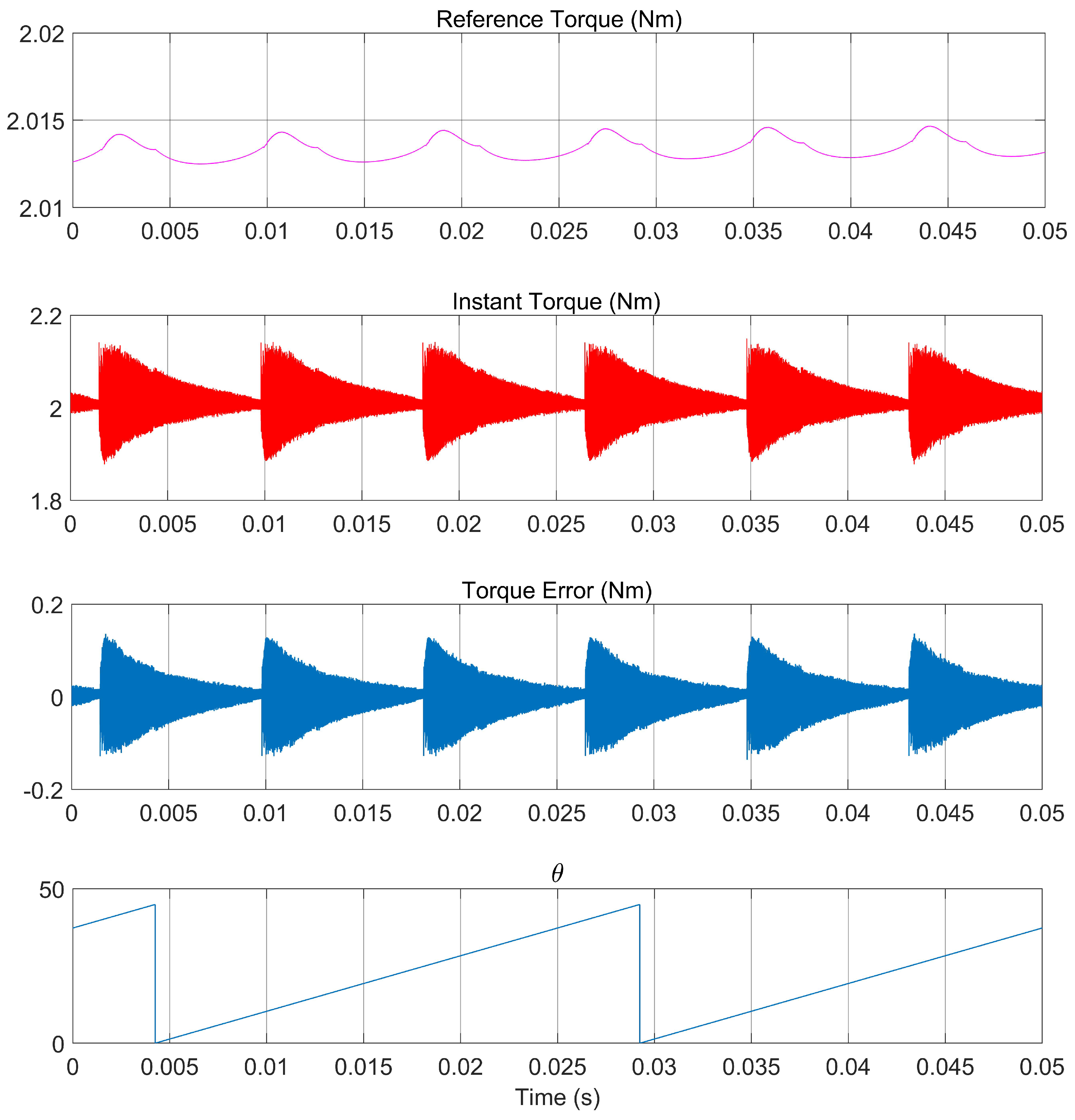
To better illustrate the proposed algorithm, the speed is set as 300 rpm, and the load torque is 2 Nm; the reference and instantaneous torque curves are shown in Figure 5. The four curves, generated according to the control structure in Figure 4, from top to bottom are reference and instant torque, torque error, and rotor angle, respectively. The torque error always exists as the speed closed loop is designed according to the motor’s mechanical equation, ignoring the speed fluctuation. At the same time, the reference torque lags behind the instant torque. The PI controller is also employed to compensate for the instability in the speed control, with inferior performance. Although more complex algorithms can be introduced to reduce the calculation time from the speed error to the given torque, they cannot fundamentally solve the problem.
3.2. RTNN
RTNN is used in the system to fine-tune the reference torque online according to the rotor angle. The working principle of RTNN is shown in Figure 6.
The PI speed controller calculates the speed error to obtain the reference torque, which constitutes the input of the neural network and the rotor angle. At the same time, the instantaneous torque is obtained via a look-up table, according to the feedback current and rotor angle. Finally, the difference between the instant and the reference torque is used to adjust the internal parameters of the neural network.
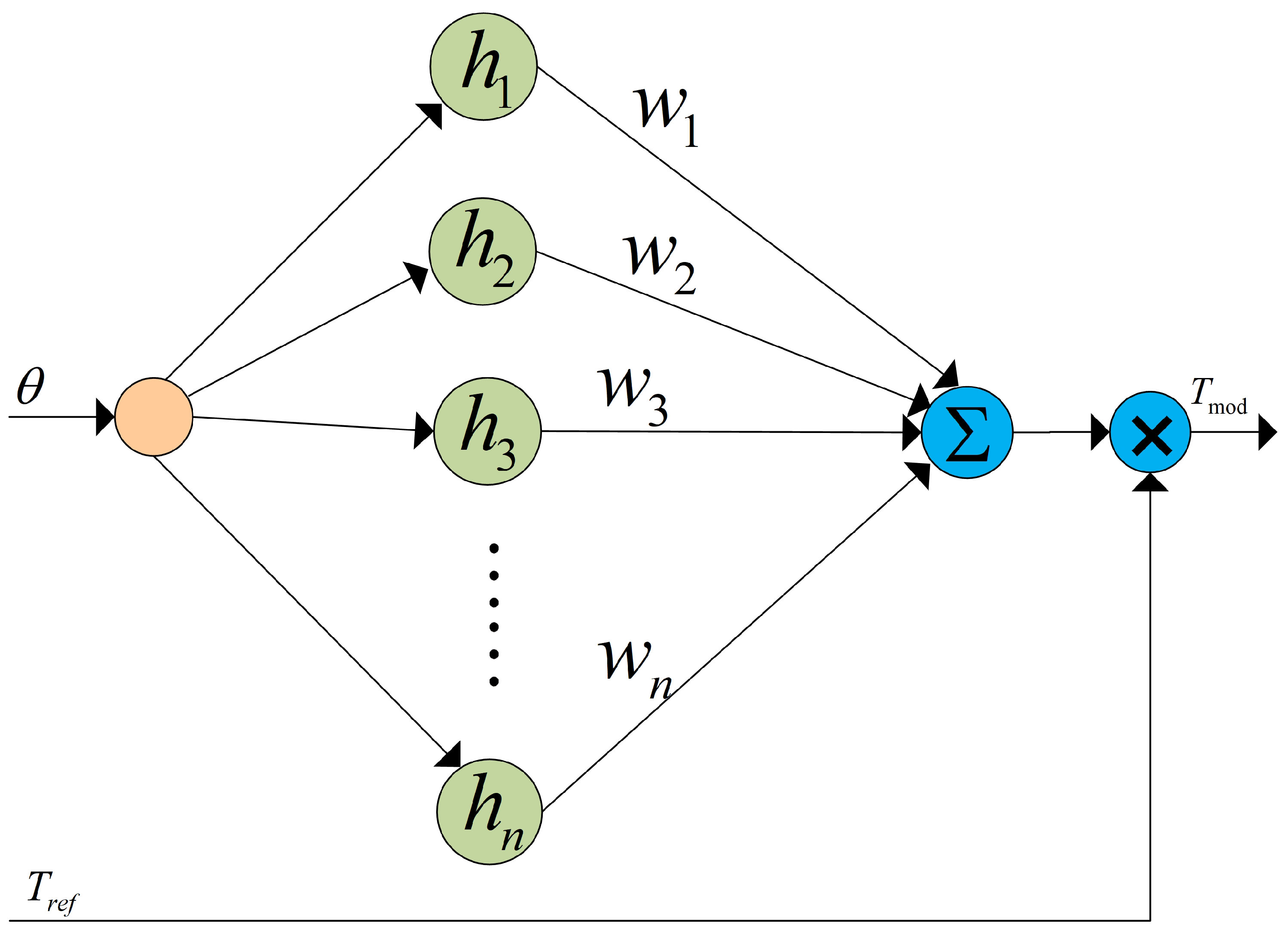
The internal structure of the constructed RTNN is shown in Figure 7.
The RBF neural network is a network with the radial basis function as its core. It is usually designed as a three-layer structure, including an input layer, hidden layer, and output layer. The neuron activation function of the hidden layer is composed of radial basis functions. The array operation of the hidden layer is called the hidden layer node. Each hidden layer contains a central vector c, which has the same dimension as the input vector X. The radial basis function is usually selected as the Gaussian function, which is
where is the Euclidean distance, is the center vector, and is the network width.
The training of the RBF network is the learning process of network parameters, including the center of the hidden layer, network width, number of hidden layer nodes, and the connection weight value from the hidden layer to the output layer. The hidden layer center is generally trained by random selection or unsupervised clustering based on data samples.
Referring to the RBF structure, the RTNN proposed in this paper is a single-input network and uses a feed-forward link. As a result, the reference torque does not go through the network node, but directly multiplies with the neural network output to obtain the corrected reference torque . Therefore, the neural network in the RTNN plays a role in adjusting the size of the reference torque according to the rotor angle.
The construction of the RTNN refers to the structure of the RBF network. The implicit function is the radial basis function, and its expression is
At the same time, the error back propagation algorithm is used to correct the weights and coefficients, where the error is defined as the square of the error, and the goal is to minimize the error.
The output of the neural network is defined as , and its expression is
The parameter learning process of neural network is
where is the learning rate.
The coefficients update equation is
where the momentum factor.
Thus, after RTNN correction, the final reference torque becomes
The center point in RBF is often random and then adjusted by the error backpropagation. Unlike the random selection of hidden layer center in the traditional RBF, in the proposed method, the RBF neural network’s center point significantly influences its tracking effect. Although the center value can be adjusted and changed by error feedback, the neural network is used to correct the reference torque online in this paper, the optimized adjustment needs to be completed in one step, and the one-step adjustment effect directly affects the size of the reference torque, which has a significant influence on the torque ripple.
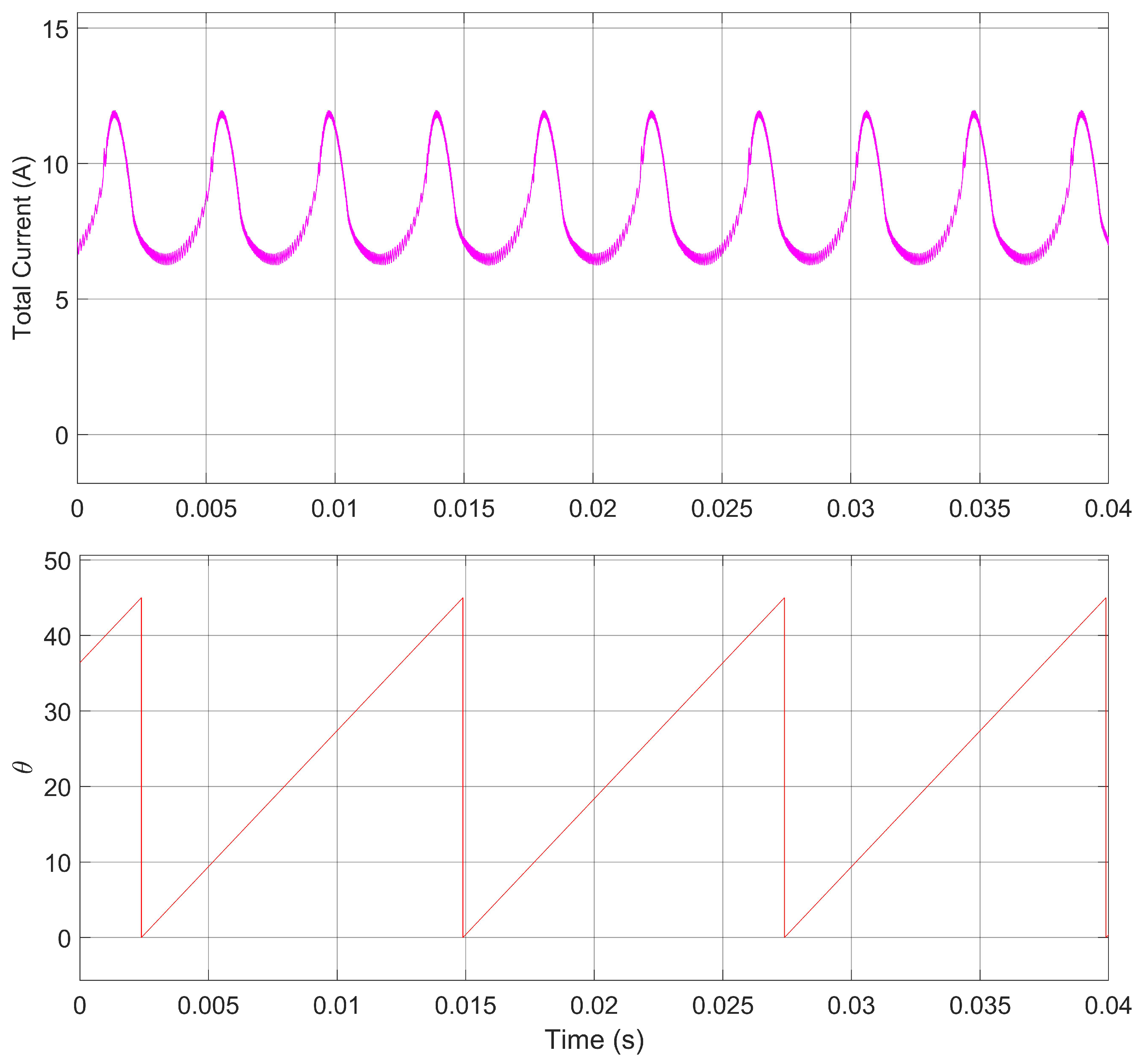
By observing the total current during SRM operation, it is found that the total current presents a regular change in approximate sine wave. There are three peaks and troughs in one rotor angle period, as shown in Figure 8. According to this characteristic, the implicit function is customized to speed up the correction of the reference torque.
According to the characteristics of 12/8 SRM, the center point of the implicit function is initialized to
Thus, after the initialization is completed, the peak points of the total current are in the middle of each phase.
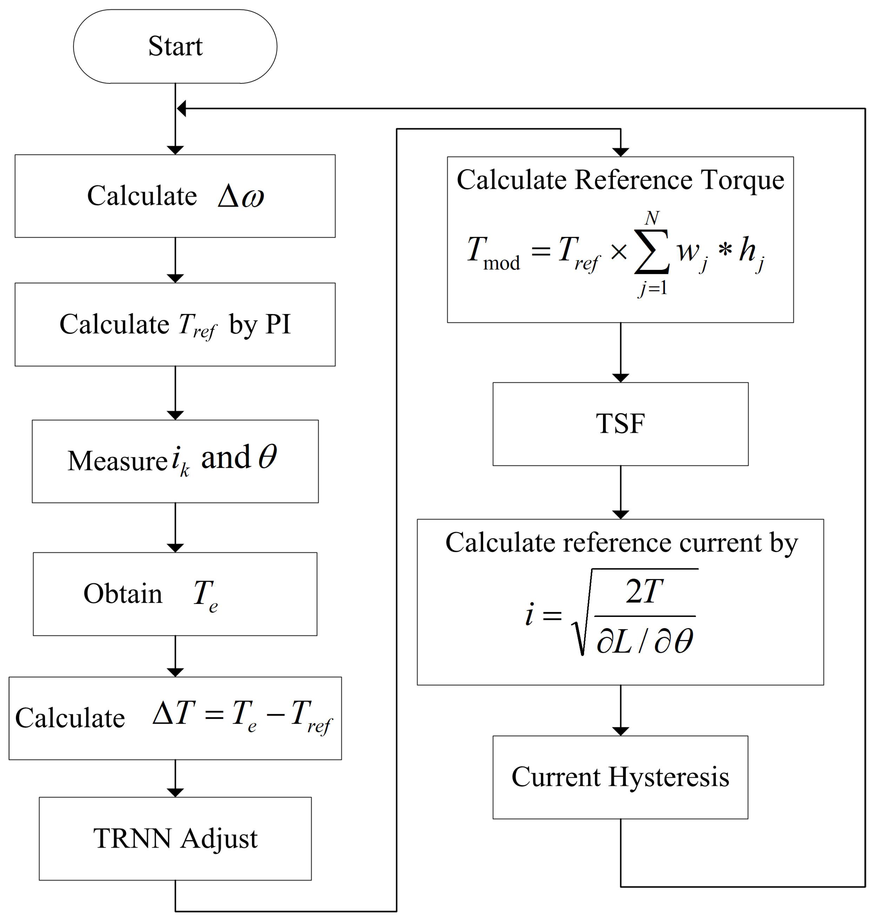
3.3. Flow Chart of Algorithm Steps
STEP 1 Calculate the speed error according to the set speed and real speed.
STEP 2 Calculate reference torque by PI controller.
STEP 3 Measure the rotor angle and phase current.
STEP 4 Obtain the instant torque according to the torque look-up table.
STEP 5 Calculate the torque error according to the reference torque and instant torque.
STEP 6 Adjust the network weight coefficient according to torque error.
STEP 7 Calculate the modified reference torque.
STEP 8 Share the reference torque by TSF.
STEP 9 Calculate reference current.
STEP 10 Current hysteresis calculation.
The RTNN adjusts the weight and width vector of the neural network in each calculation step, as shown in Figure 9. Therefore, the output modified the reference torque periodically according to the rotor angle. RTNN is an online parameter adjustment method. Hence, its one-step adjustment results are directly used to generate the reference torque.
4. Verify Simulation
To verify the proposed algorithm’s correctness and compare it with the PD compensation algorithm, the simulation model of switched reluctance motor is built in MATLAB/Simulink. The SRM chosen is the 12/8 type, with rated voltage 240 V, rated speed 3000 rpm, stator resistance 0.01 , stator alignment at the maximum inductance 0.00015 mH, friction coefficient 0.01 N.m.s, and inertia 0.0082 kg·m.
In the simulation, the inner loop is the current loop control, and the current hysteresis loop is symmetrically designed as 0.1 A. This method is compared with the fuzzy and PD compensation algorithm. In the PD compensation algorithm, the total current is obtained first, and then the total current is distributed. The proposed RTNN compensates the reference torque first, then the corrected reference torque is distributed, and finally, the torque to current conversion is performed. The distribution method used in the above three methods, whether or not the torque or current is distributed, is the cubic distribution function. As a result, the essence of the distribution of reference torque first, then torque–current conversion, and first torque–current conversion, then current distribution is the same.
In order to better measure the suppression of torque ripple under different control methods, the calculation formula of torque ripple is designed in the form of Equation (14).
where is torque ripple, is maximum torque during the measuring circle, is minimum torque during the measuring circle, and is average torque during the measuring circle.
Considering the response characteristics of the actual motor object, the torque table used in the simulation is based on the data obtained from the actual motor test. The instantaneous torque in the simulation is obtained by testing the actual electromagnetic torque by fixing the rotor at different rotor angles and providing different currents to measure its electromagnetic torque. The electromagnetic torque in simulation is also provided by the established torque table. It corresponds to the real-world motor output.
Thus, the RTNN proposed in this paper is compared with the fuzzy and PD compensation method. The parameters of the PD compensator were optimized and selected as and . The central value in RTNN is given as above, and the other parameters are specified as and , The neural network node is selected to be 7, w is initialized to a 1-row 7-column matrix of 5, and b and c are initialized to a 1-row 7-column matrix of 10 and 1.5.
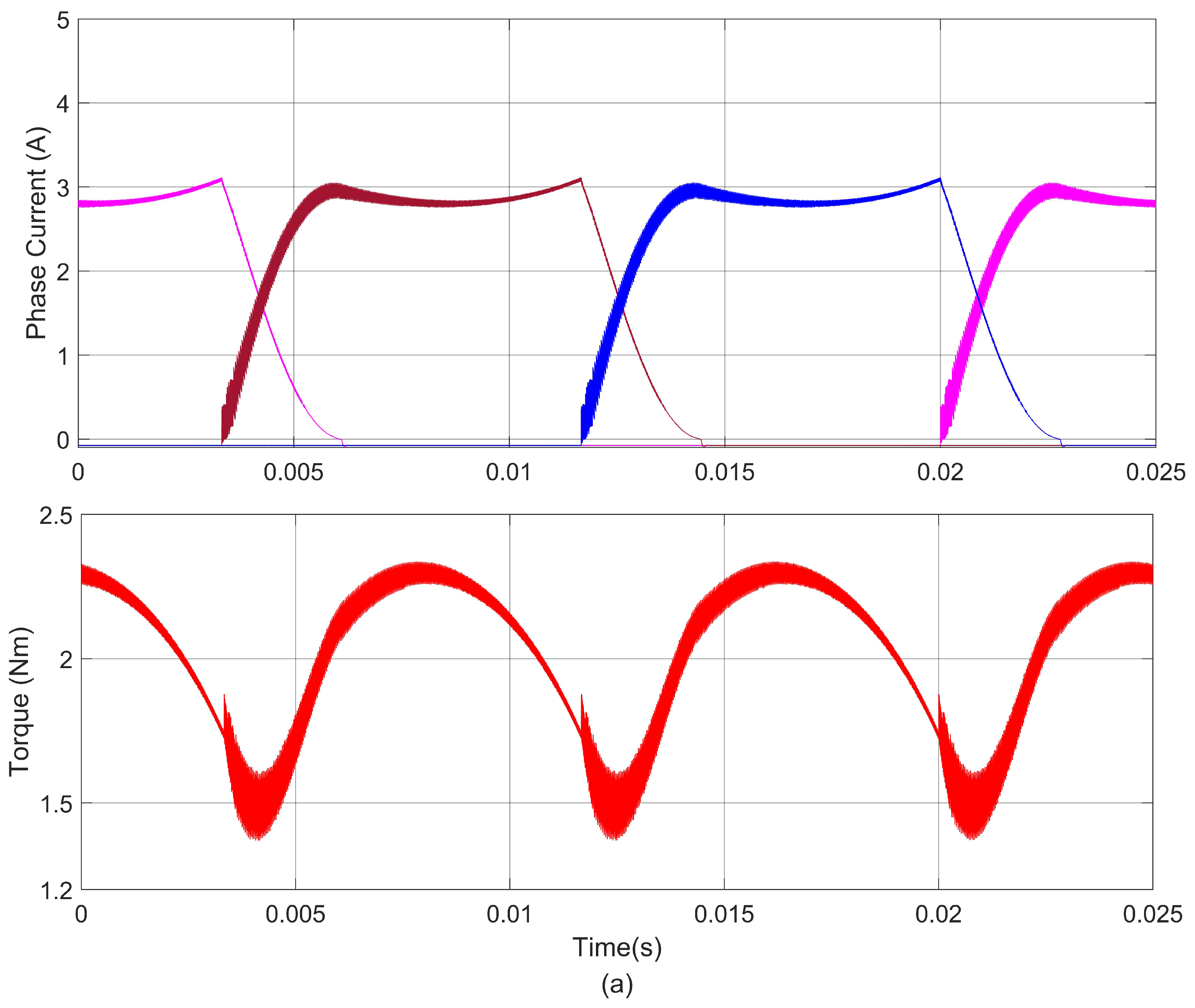
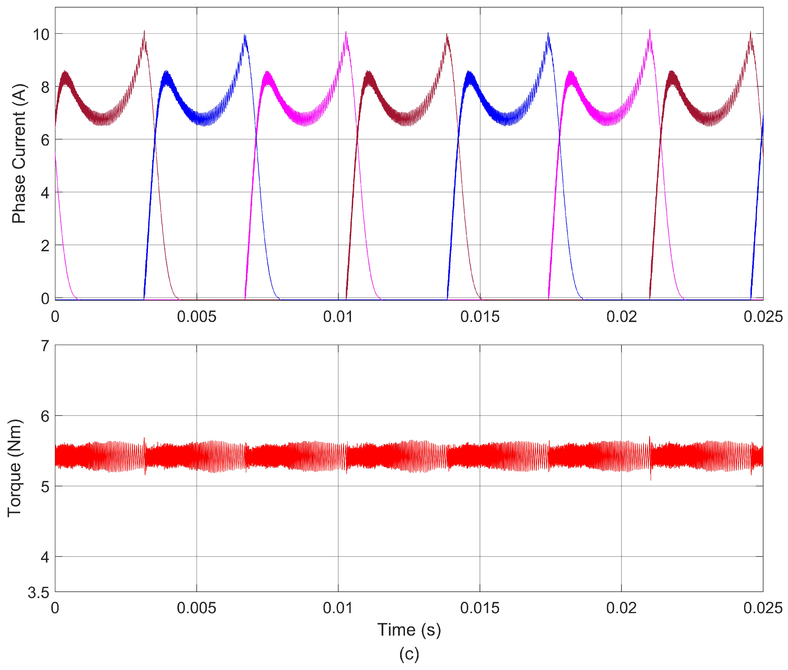
The load torque is set to 2 Nm, and the speed is 300 rpm. The three methods mentioned above are used to compensate respectively. The simulation results are shown in Figure 10. Figure 10a–c show the torque and current response curves using the fuzzy compensation method, PD compensation method, and the proposed RTNN method, respectively. The more significant value of torque ripple is generated during the commutation process. The torque ripples caused by the fuzzy compensation, PD compensation algorithm and the RTNN algorithm are 47.5%, 20.9%, and 13.5%, respectively. With the proposed RTNN, the torque ripple can be reduced by 71% and 35%.
The fuzzy compensation algorithm has a minimal ability to reduce torque ripple. In addition, as the reference torque lags behind the instantaneous torque, the fuzzy algorithm can not correct the lag problem by compensating the reference torque. The PD compensation algorithm cannot adjust the compensation current value according to the rotor angle due to its fixed parameters. Therefore, it only relies on the reference torque error to compensate, and the improved performance is limited. On the other hand, the RTNN method adjusts the compensation system according to the rotor angle. It fully considers that the torque ripple of SRM is enormous in the commutation process. Therefore, the reference torque is adjusted according to the torque error, and the effect of suppressing the torque ripple is noticeable.
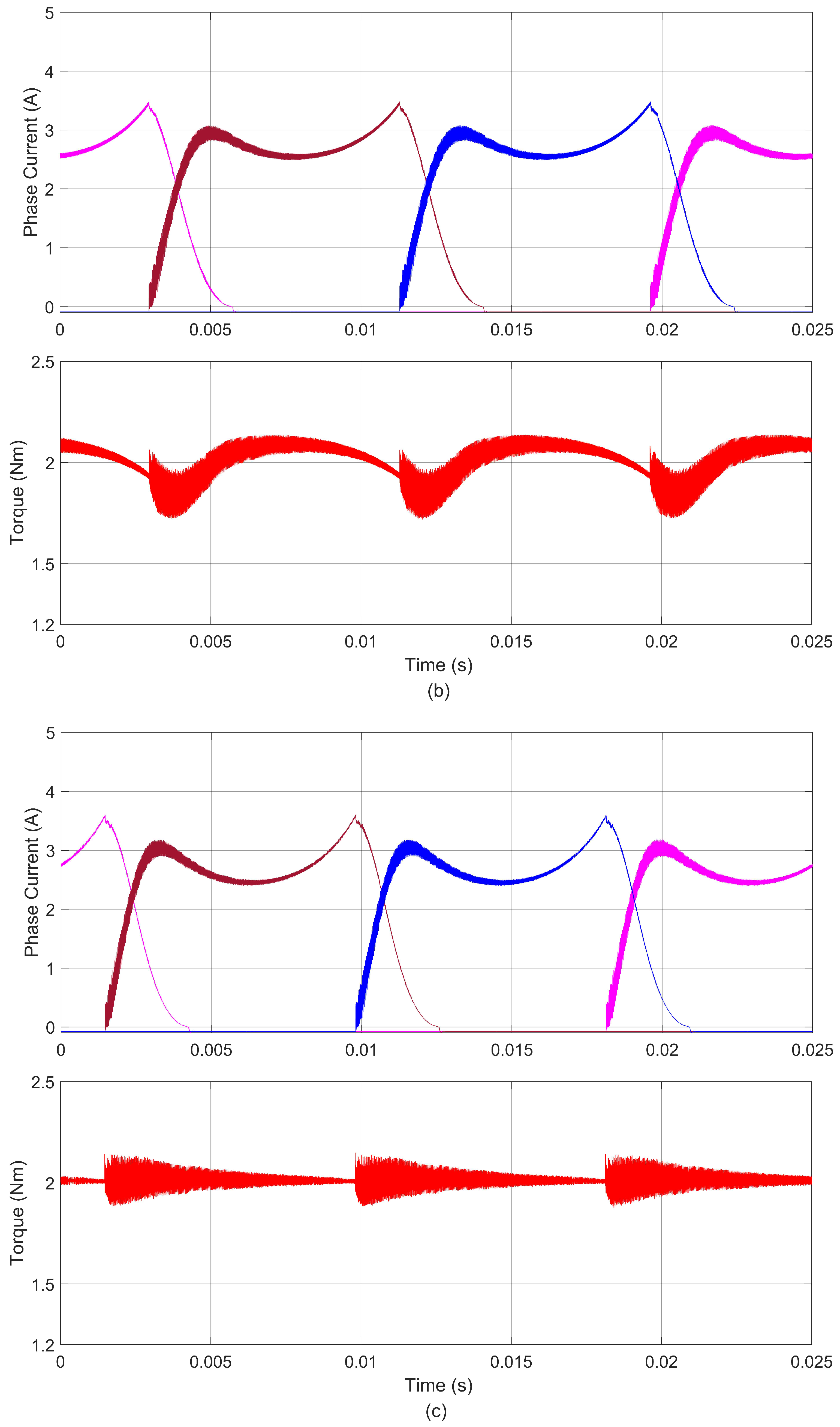
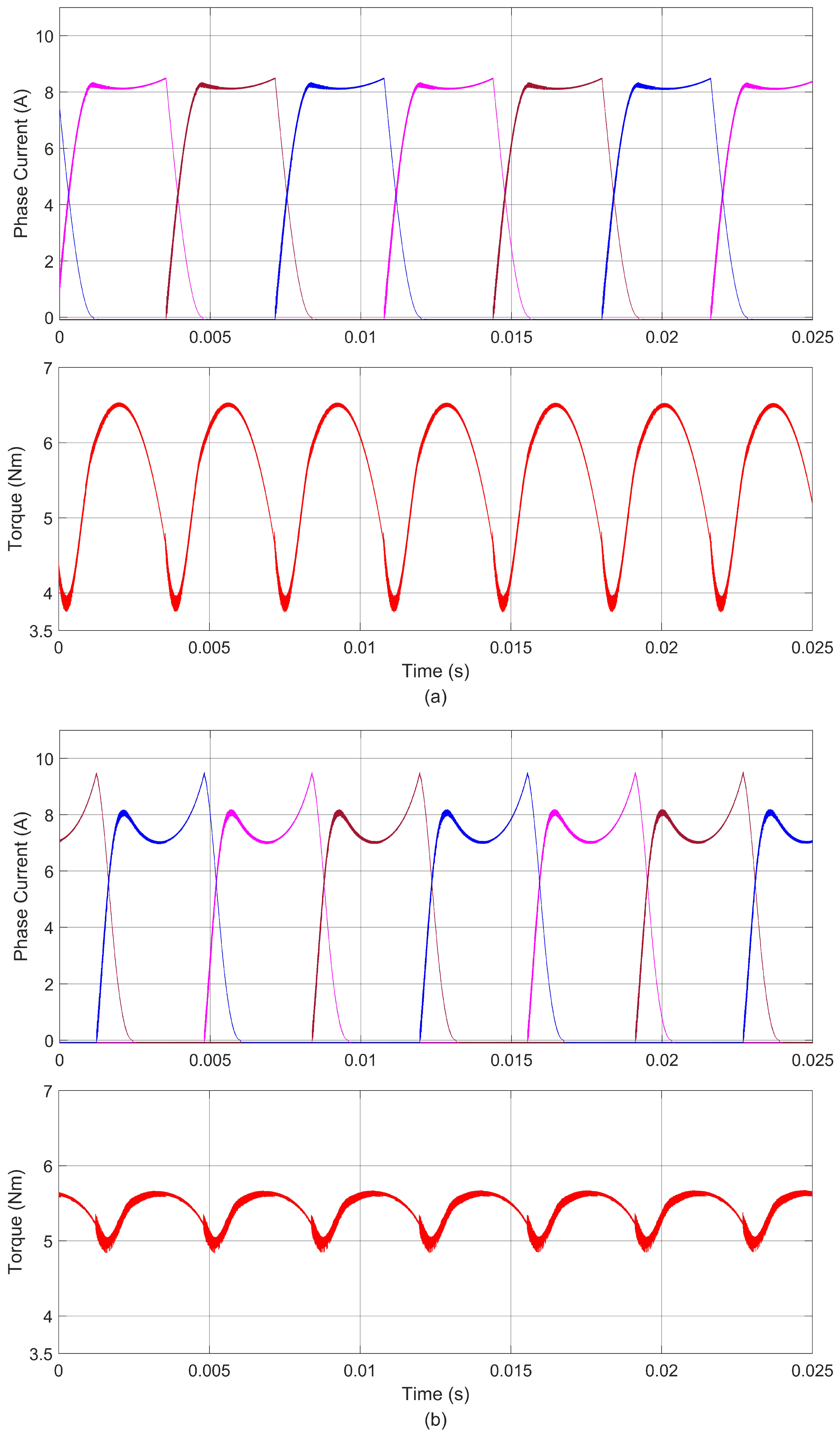
Similarly, the load torque is changed to 5 Nm, and the speed is adjusted to 700 rpm. The fuzzy compensation, PD compensation, and RTNN methods proposed in this paper are also compared and tested. The simulation results are shown in Figure 11. The torque ripples generated by the fuzzy compensation, PD compensation algorithm, and the RTNN algorithm are 51.7 %, 15.7%, and 11.8%, respectively, and the torque ripples are reduced by 77% and 25% with the proposed RTNN. Through the performance of torque ripple, it is found that the torque ripple is reduced to varying degrees after increasing the speed and load torque.
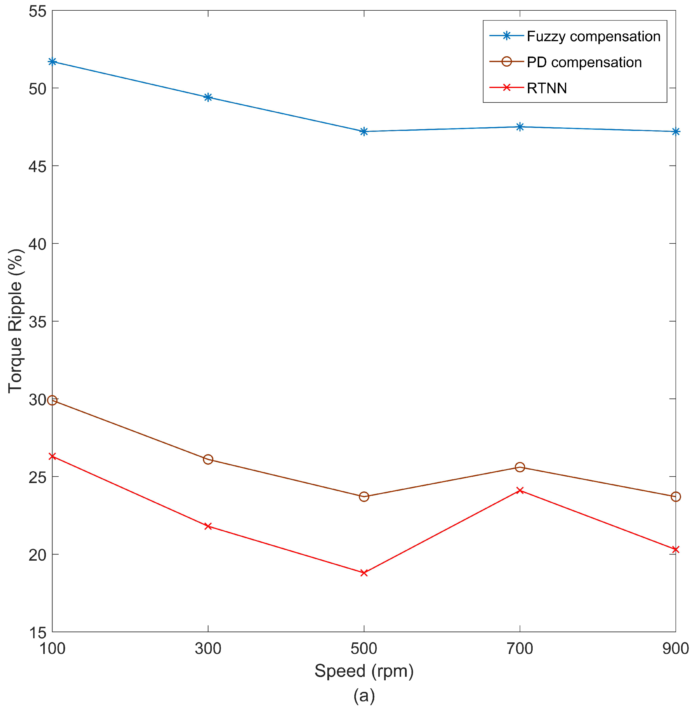
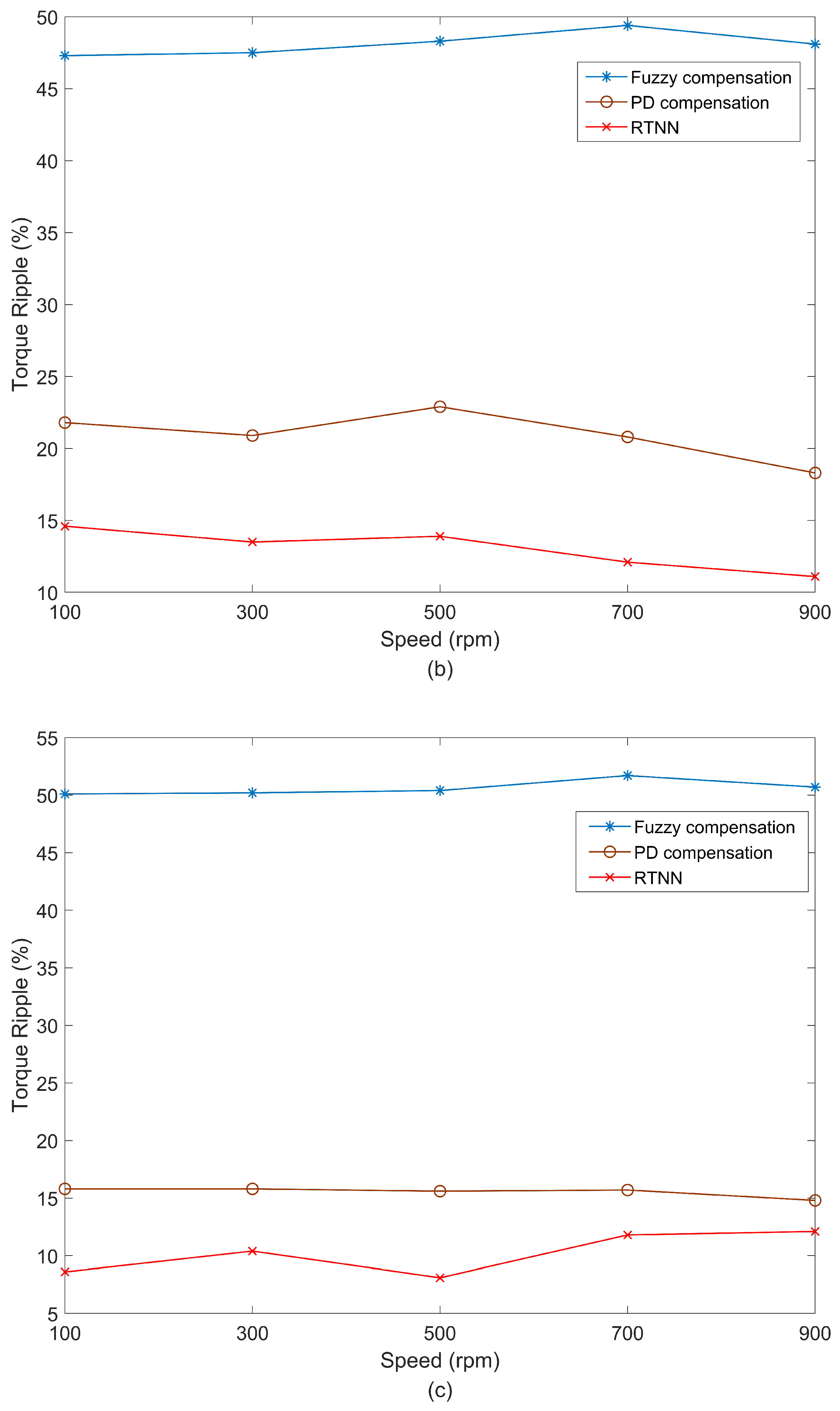
The performance of the three methods at different operating points is shown in Figure 12, with speed changed from 100 rpm to 900 rpm, an interval of 200 rpm, and with a load torque of 1 Nm, 2 Nm, and 5 Nm, respectively. The specific torque ripple value is shown in Table 1. The numerical results show that the torque ripple of the fuzzy compensation algorithm is unchanged with the torque increase. In contrast, the torque ripple of PD and RTNN algorithms decreased. In the case of small load torque, the effect of the RTNN algorithm to reduce torque ripple is not apparent, mainly because, in this case, small control current changes will cause significant electromagnetic torque changes. Therefore, the electromagnetic torque is not easily controlled.
The advantages, disadvantages, and performance comparisons of the three algorithms are shown in Table 2. The fuzzy compensation algorithm can optimize the reference torque, which can combine well with the human experience, but searching the fuzzy rule table consumes more processor time and increases the algorithm’s complexity. PD algorithm is a model-free compensation algorithm that realizes the calculation from torque error to compensation current. The computation is low, but its parameters are fixed, so the adjustment amount is fixed. The RTNN algorithm aims at optimizing the reference torque, has the ability of self-learning, needs model information, and requires rotor angle accuracy. The suppression is evident using the method proposed in this paper. The torque ripple suppression effect of the proposed RTNN method is better than that of the fuzzy and PD compensation methods under different operating conditions.
5. Conclusions
To reduce the torque ripple in the SRM, this paper proposes an online neural network based on the TSF method that adjusts the reference torque online. Considering the periodic relationship between the fluctuation of torque ripple and the rotor angle, the implicit function of RTNN is directly related to the rotor angle, and the center point of the implicit function is set according to the current characteristics of SRM. Therefore, the one-step adjustment of RTNN can better suppress the torque ripple. Compared with the fuzzy torque compensation and PD current compensation methods, it is found that the torque ripple is effectively reduced under different loads and speeds.
The RTNN algorithm proposed in this paper can optimize the reference torque in one step, requiring high angle measurement accuracy. In future research, RTNN can be developed into a recurrent neural network in which the optimized value of the previous cycle can be used to optimize the next motorcycle. Therefore, online iterative optimization can be realized, and the effect will be further improved.
Author Contributions
Conceptualization, B.J.; Data curation, B.J.; Formal analysis, B.J., X.D. and Z.L.; Investigation, B.J., Z.L. and J.J.; Methodology, B.J. and X.D.; Software, B.J., Z.L. and J.J.; Supervision, X.D., Z.L. and J.J.; Writing—original draft, B.J.; Writing—review and editing, X.D., Z.L. and J.J. All authors have read and agreed to the published version of the manuscript.
Funding
This work was financially supported partly by the National Natural Science Foundation of China under Grant 61863008 and Grant 62263009 and partly by the Fundamental Ability Enhancement Project for Young and Middle-aged University Teachers in Guangxi Province under Grant 2021KY0801.
Institutional Review Board Statement
Not applicable.
Informed Consent Statement
Not applicable.
Data Availability Statement
Not applicable.
Conflicts of Interest
The authors declare no conflict of interest.
References
- Bostanci, E.; Moallem, M.; Parsapour, A.; Fahimi, B. Opportunities and Challenges of Switched Reluctance Motor Drives for Electric Propulsion: A Comparative Study. IEEE Trans. Transp. Electrif. 2017, 3, 58–75. [Google Scholar] [CrossRef]
- Castano, S.M.; Bilgin, B.; Lin, J.; Emadi, A. Radial forces and vibration analysis in an external-rotor switched reluctance machine. IET Electr. Power Appl. 2017, 11, 252–259. [Google Scholar] [CrossRef]
- Ahn, J.-W.; Lukman, G.F. Switched reluctance motor: Research trends and overview. CES Trans. Electr. Mach. Syst. 2018, 2, 339–347. [Google Scholar] [CrossRef]
- Gan, C.; Wu, J.; Sun, Q.; Kong, W.; Li, H.; Hu, Y. A Review on Machine Topologies and Control Techniques for Low-Noise Switched Reluctance Motors in Electric Vehicle Applications. IEEE Access 2018, 6, 31430–31443. [Google Scholar] [CrossRef]
- Fang, G.; Scalcon, F.P.; Xiao, D.; Vieira, R.P.; Gründling, H.A.; Emadi, A. Advanced Control of Switched Reluctance Motors (SRMs): A Review on Current Regulation, Torque Control and Vibration Suppression. IEEE Open J. Ind. Electron. Soc. 2021, 2, 280–301. [Google Scholar] [CrossRef]
- Mikail, R.; Husain, I.; Sozer, Y.; Islam, M.S.; Sebastian, T. A Fixed Switching Frequency Predictive Current Control Method for Switched Reluctance Machines. IEEE Trans. Ind. Appl. 2014, 50, 3717–3726. [Google Scholar] [CrossRef]
- Xu, A.; Shang, C.; Chen, J.; Zhu, J.; Han, L. A New Control Method Based on DTC and MPC to Reduce Torque Ripple in SRM. IEEE Access 2019, 7, 68584–68593. [Google Scholar] [CrossRef]
- Shang, C.; Xu, A.; Huang, L.; Chen, J. Flux linkage optimization for direct torque control of switched reluctance motor based on model predictive control. IEEJ Trans. Electr. Electron. Eng. 2019, 14, 1105–1113. [Google Scholar] [CrossRef]
- Li, X.; Shamsi, P. Model Predictive Current Control of Switched Reluctance Motors With Inductance Auto-Calibration. IEEE Trans. Ind. Electron. 2016, 63, 3934–3941. [Google Scholar] [CrossRef]
- Valencia, D.F.; Tarvirdilu-Asl, R.; Garcia, C.; Rodriguez, J.; Emadi, A. A Review of Predictive Control Techniques for Switched Reluctance Machine Drives. Part I: Fundamentals and Current Control. IEEE Trans. Energy Convers. 2021, 36, 1313–1322. [Google Scholar] [CrossRef]
- Li, H.; Bilgin, B.; Emadi, A. An Improved Torque Sharing Function for Torque Ripple Reduction in Switched Reluctance Machines. IEEE Trans. Power Electron. 2019, 34, 1635–1644. [Google Scholar] [CrossRef]
- Xia, Z.; Bilgin, B.; Nalakath, S.; Emadi, A. A New Torque Sharing Function Method for Switched Reluctance Machines with Lower Current Tracking Error. IEEE Trans. Ind. Electron. 2020, 68, 10612–10622. [Google Scholar] [CrossRef]
- Xia, Z.; Fang, G.; Xiao, D.; Emadi, A.; Bilgin, B. An Online Torque Sharing Function Method Involving Current Dynamics for Switched Reluctance Motor Drives. IEEE Trans. Transp. Electrif. 2022. [Google Scholar] [CrossRef]
- Rana, A.K.; Raviteja, A. A Mathematical Torque Ripple Minimization Technique Based on Nonlinear Modulating Factor for Switched Reluctance Motor Drives. IEEE Trans. Ind. Electron. 2021, 69, 1356–1366. [Google Scholar] [CrossRef]
- Zhang, Z. Sensorless Back EMF Based Control of Synchronous PM and Reluctance Motor Drives—A Review. IEEE Trans. Power Electron. 2022, 37, 10290–10305. [Google Scholar] [CrossRef]
- Lopac, N.; Bulić, N.; Vrkić, N. Sliding Mode Observer-Based Load Angle Estimation for Salient-Pole Wound Rotor Synchronous Generators. Energies 2019, 12, 1609. [Google Scholar] [CrossRef] [Green Version]
- Dong-Hee, L.; Jianing, L.; Zhen-Guo, L.; Jin-Woo, A. A Simple Nonlinear Logical Torque Sharing Function for Low-Torque Ripple SR Drive. IEEE Trans. Ind. Electron. 2009, 56, 3021–3028. [Google Scholar] [CrossRef]
- Song, S.; Hei, R.; Ma, R.; Liu, W. Model Predictive Control of Switched Reluctance Starter/Generator With Torque Sharing and Compensation. IEEE Trans. Transp. Electrif. 2020, 6, 1519–1527. [Google Scholar] [CrossRef]
- Ye, J.; Bilgin, B.; Emadi, A. An Offline Torque Sharing Function for Torque Ripple Reduction in Switched Reluctance Motor Drives. IEEE Trans. Energy Convers. 2015, 30, 726–735. [Google Scholar] [CrossRef]
- Ye, J.; Bilgin, B.; Emadi, A. An Extended-Speed Low-Ripple Torque Control of Switched Reluctance Motor Drives. IEEE Trans. Power Electron. 2015, 30, 1457–1470. [Google Scholar] [CrossRef]
- Changhwan, C.; Seungho, K.; Yongdae, K.; Kyihwan, P. A new torque control method of a switched reluctance motor using a torque-sharing function. IEEE Trans. Magn. 2002, 38, 3288–3290. [Google Scholar] [CrossRef]
- Xue, X.D.; Cheng, K.W.E.; Ho, S.L. Optimization and Evaluation of Torque-Sharing Functions for Torque Ripple Minimization in Switched Reluctance Motor Drives. IEEE Trans. Power Electron. 2009, 24, 2076–2090. [Google Scholar] [CrossRef] [Green Version]
- Mir, S.; Elbuluk, M.E.; Husain, I. Torque-ripple minimization in switched reluctance motors using adaptive fuzzy control. IEEE Trans. Ind. Appl. 1999, 35, 461–468. [Google Scholar] [CrossRef]
- Song, S.; Huang, S.; Zhao, Y.; Zhao, X.; Duan, X.; Ma, R.; Liu, W. Torque Ripple Reduction of Switched Reluctance Machine with Torque Distribution and Online Correction. IEEE Trans. Ind. Electron. 2022. [Google Scholar] [CrossRef]
- Jing, B.; Dang, X.; Liu, Z.; Long, S. Torque Ripple Suppression of Switched Reluctance Motor Based on Fuzzy Indirect Instant Torque Control. IEEE Access 2022, 10, 75472–75481. [Google Scholar] [CrossRef]
- Sahoo, N.C.; Xu, J.X.; Panda, S.K. Low Torque Ripple Control of Switched Reluctance Motors Using Iterative Learning. IEEE Power Eng. Rev. 2001, 21, 66. [Google Scholar] [CrossRef]
- Zhu, Z.Q.; Lee, B.; Huang, L.; Chu, W. Contribution of Current Harmonics to Average Torque and Torque Ripple in Switched Reluctance Machines. IEEE Trans. Magn. 2017, 53, 1–9. [Google Scholar] [CrossRef]
- Mikail, R.; Husain, I.; Sozer, Y.; Islam, M.S.; Sebastian, T. Torque-Ripple Minimization of Switched Reluctance Machines through Current Profiling. IEEE Trans. Ind. Appl. 2013, 49, 1258–1267. [Google Scholar] [CrossRef]
- Reddy, B.P.; Vemula, J.R.; Keerthipati, S. Torque ripple minimisation of switched reluctance motor using sense coils. IET Electr. Power Appl. 2020, 14, 614–621. [Google Scholar] [CrossRef]
- Ma, M.; Ling, F.; Li, F.; Liu, F. Torque ripple suppression of switched reluctance motor by segmented harmonic currents injection based on adaptive fuzzy logic control. IET Electr. Power Appl. 2020, 14, 325–335. [Google Scholar] [CrossRef]
- Cheng, H.; Chen, H.; Yang, Z.; Huang, W. Braking Torque Closed-Loop Control of Switched Reluctance Machines for Electric Vehicles. J. Power Electron. 2015, 15, 469–478. [Google Scholar] [CrossRef] [Green Version]
- Ro, H.-S.; Lee, K.-G.; Lee, J.-S.; Jeong, H.-G.; Lee, K.-B. Torque ripple minimization scheme using torque sharing function based fuzzy logic control for a switched reluctance motor. J. Electr. Eng. Technol. 2015, 10, 118–127. [Google Scholar] [CrossRef] [Green Version]
- Narendra, K.S.; Parthasarathy, K. Identification and control of dynamical systems using neural networks. IEEE Trans. Neural Netw. 1990, 1, 4–27. [Google Scholar] [CrossRef] [PubMed] [Green Version]
- Hoai, H.-K.; Chen, S.-C.; Chang, C.-F. Realization of the Neural Fuzzy Controller for the Sensorless PMSM Drive Control System. Electronics 2020, 9, 1371. [Google Scholar] [CrossRef]
- Rahman, K.M.; Gopalakrishnan, S.; Fahimi, B.; Rajarathnam, A.V.; Ehsani, M. Optimized torque control of switched reluctance motor at all operational regimes using neural network. IEEE Trans. Ind. Appl. 2001, 37, 904–913. [Google Scholar] [CrossRef]
- Cao, G.; Chen, N.; Huang, S.; Xiao, S.; He, J. Nonlinear Modeling of the Flux Linkage in 2-D Plane for the Planar Switched Reluctance Motor. IEEE Trans. Magn. 2018, 54, 1–5. [Google Scholar] [CrossRef]
- Zhang, Z.; Rao, S.; Zhang, X. Performance prediction of switched reluctance motor using improved generalized regression neural networks for design optimization. CES Trans. Electr. Mach. Syst. 2018, 2, 371–376. [Google Scholar] [CrossRef]
- Dang, X.; Shi, Y.; Peng, H. Torque–flux linkage recurrent neural network adaptive inversion control of torque for switched reluctance motor. IET Electr. Power Appl. 2020, 14, 1612–1623. [Google Scholar] [CrossRef]
Figure 1.
TSF control schematic.

Figure 2.
Reference torque compensation by fuzzy controller.

Figure 3.
Compensation by PD controller.

Figure 4.
RTNN structure.

Figure 5.
Curves of reference torque and instantaneous torque.

Figure 6.
Framework of the RTNN.

Figure 7.
RTNN internal node.

Figure 8.
Relationship between total current and rotor angle.

Figure 9.
Algorithm flow chart.

Figure 10.
Phase current and electromagnetic torque at 2 Nm, 300 rpm with (a) fuzzy compensator, (b) PD compensator, and (c) RTNN.
Figure 10.
Phase current and electromagnetic torque at 2 Nm, 300 rpm with (a) fuzzy compensator, (b) PD compensator, and (c) RTNN.


Figure 11.
Phase current and electromagnetic torque at 5 Nm, 700 rpm with (a) fuzzy compensator, (b) PD compensator, and (c) RTNN.
Figure 11.
Phase current and electromagnetic torque at 5 Nm, 700 rpm with (a) fuzzy compensator, (b) PD compensator, and (c) RTNN.


Figure 12.
Torque ripple compare under different speeds with (a) 1 Nm torque load, (b) 2 Nm torque load, and (c) 5 Nm torque load.
Figure 12.
Torque ripple compare under different speeds with (a) 1 Nm torque load, (b) 2 Nm torque load, and (c) 5 Nm torque load.


Table 1.
Torque ripple comparison of the three methods (%).
| Torque Load | Control Method | 100 rpm | 300 rpm | 500 rpm | 700 rpm | 900 rpm |
|---|---|---|---|---|---|---|
| 1 Nm | Fuzzy compensation | 51.7 | 49.4 | 47.2 | 47.5 | 47.2 |
| PD compensation | 29.9 | 26.1 | 23.7 | 25.6 | 23.7 | |
| RTNN | 26.3 | 21.8 | 18.8 | 24.1 | 20.3 | |
| 2 Nm | Fuzzy compensation | 47.3 | 47.5 | 48.3 | 49.4 | 48.1 |
| PD compensation | 21.8 | 20.9 | 22.9 | 20.8 | 18.3 | |
| RTNN | 14.6 | 13.5 | 13.9 | 12.1 | 11.1 | |
| 5 Nm | Fuzzy compensation | 50.1 | 50.2 | 50.4 | 51.7 | 50.7 |
| PD compensation | 15.8 | 15.8 | 15.6 | 15.7 | 14.8 | |
| RTNN | 8.6 | 10.4 | 8.1 | 11.8 | 12.1 |
Table 2.
Performance comparison of the three methods.
| Technique | Advantages | Disadvantages | Model Information | Computational Complexity | Optimization Object |
|---|---|---|---|---|---|
| Fuzzy compensation | Artificial experience | Costly at searching table | No | Medium | Reference torque |
| PD compensation | Simplicity | Fixed adjustment | No | Low | Reference current |
| RTNN | Learning ability | Rely on accurate rotor angle | Yes | Medium | Reference torque |
Disclaimer/Publisher’s Note: The statements, opinions and data contained in all publications are solely those of the individual author(s) and contributor(s) and not of MDPI and/or the editor(s). MDPI and/or the editor(s) disclaim responsibility for any injury to people or property resulting from any ideas, methods, instructions or products referred to in the content. |
© 2023 by the authors. Licensee MDPI, Basel, Switzerland. This article is an open access article distributed under the terms and conditions of the Creative Commons Attribution (CC BY) license (https://creativecommons.org/licenses/by/4.0/).
Share and Cite
MDPI and ACS Style
Jing, B.; Dang, X.; Liu, Z.; Ji, J. Torque Ripple Suppression of Switched Reluctance Motor with Reference Torque Online Correction. Machines 2023, 11, 179. https://doi.org/10.3390/machines11020179
AMA Style
Jing B, Dang X, Liu Z, Ji J. Torque Ripple Suppression of Switched Reluctance Motor with Reference Torque Online Correction. Machines. 2023; 11(2):179. https://doi.org/10.3390/machines11020179
Chicago/Turabian StyleJing, Benqin, Xuanju Dang, Zheng Liu, and Jianbo Ji. 2023. "Torque Ripple Suppression of Switched Reluctance Motor with Reference Torque Online Correction" Machines 11, no. 2: 179. https://doi.org/10.3390/machines11020179
Note that from the first issue of 2016, this journal uses article numbers instead of page numbers. See further details here.