

A Review of Lightweight Design for Space Mirror Core Structure: Tradition and Future

1
Changchun Institute of Optics, Fine Mechanics and Physics, Chinese Academy of Sciences, Changchun 130033, China
2
University of Chinese Academy of Sciences, Beijing 100049, China
3
Key Laboratory of Space-Based Dynamic and Rapid Optical Imaging Technology, Chinese Academy of Sciences, Changchun 130033, China
*
Author to whom correspondence should be addressed.
Machines 2022, 10(11), 1066; https://doi.org/10.3390/machines10111066
Submission received: 11 October 2022
/
Revised: 4 November 2022
/
Accepted: 7 November 2022
/
Published: 11 November 2022
(This article belongs to the Special Issue 3D-Printed Machine Elements and Mechanical Devices)
Abstract
:With the continuous improvement of the imaging quality requirement of the space optical system, the large-aperture mirror becomes the research focus. However, the increase of the aperture will increase the whole weight which results in high launch cost and degrades the mirror surface figure accuracy. Therefore, the lightweight design method of the mirror structure is of great importance. In recent years, many space telescope system schemes have demonstrated the progress of the structural lightweight design of mirrors, such as Spitzer, SOFIA, JWST, etc. This article reviews the main content and innovations of the research on the structural designs of mirrors including conventional machining designs and topology optimization structures. Meanwhile, some emerging designs (e.g., lattices and Voronoi structures) considering additive manufacturing (AM) are also introduced. Several key elements of different structural design approaches for lightweight mirrors are discussed and compared, such as material, lightweight ratio, design methods, surface figure, etc. Finally, future challenges, trends, and prospects of lightweight design for mirrors are discussed. This article provides a reference for further related research and engineering applications.
1. Introduction
With the increasingly important applications of modern space optical technology in civilian, military, and commercial fields, there is a demand for optical systems with the improvement of resolution [1]. As we know, the larger the aperture of the telescope, the longer the focal length, and the better to obtain a stronger light collection ability and higher resolution [2]. It’s noteworthy that mirrors, as the core component of the telescope, are critical elements that directly affect the resolution and other optical systems’ characteristics. Meanwhile, the increase of the aperture of the space mirror will enlarge the weight of the whole structural system, thus raising the launch cost. Consequently, to reduce the cost, and to control the rigid body motion and surface figure error of the mirror under the gravity load, the space mirror must be lightweight [3]. The design and optimization of lightweight mirrors have become a major challenge for optical scientists and engineers [4].
Over the last decades, multifarious lightweight design methods have been proposed, among which contoured-back solid mirrors, open-back mirrors, and sandwich mirrors are the most representatively and widely used in engineering (Figure 1a–c) [5]. These conventional designs are convenient to be designed and processed, and many researchers designed the mirror assembly by experience. However, with increasing requirements of the mass and precision requirement of optical-space systems, the mirrors must be further optimized. Topology optimization has been developed as a mainstream structural design technique for lightweight design. On the one hand, the mirror’s structures with a conventional design could be optimized as a starting point to obtain ameliorated structure (Figure 1d) [6]. On the other hand, due to the development of manufacturing technology, complex structures obtained by topology optimization can be directly processed. Subsequently, with the use of 3D printing in opto-mechanical manufacturing, newly unconventional structures are adopted gradually in recent years, which opens a special spectrum of creativity for mirror design. The work of design and optimization of lattices and Voronoi structures of lightweight mirror have been brought forward and the prototypes printed in metals also show excellent performance [7]. Figure 1e,f highlight some examples of how lattices and Voronoi cells were implemented in lightweight design [8,9].
This paper aims to review the recent advances in lightweight mirror designs and provide future trends. Firstly, the summary and comparison among conventional designs have been made in Section 2. Some research progress and innovations on topology optimization for reduced-weight mirrors are listed in Section 3. Then, Section 4 introduces non-conventional designs, especially lattices and Voronoi structures for mirrors. Lightweight mirrors’ current process and future trends are discussed in Section 5. Finally, Section 6 illustrates the conclusion.
2. Conventional Design
2.1. Contoured-Back Solid Mirrors
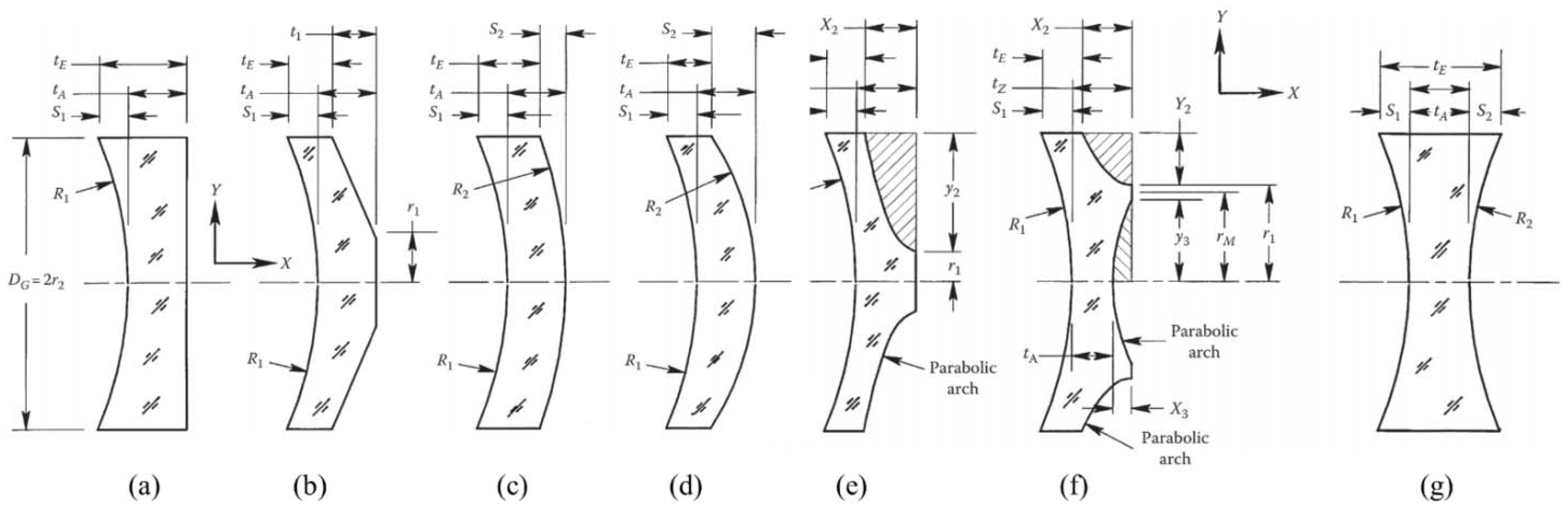
Thinning the baseline substrate is a rapid and convenient way to lightweight solid mirrors with concave, flat, and convex first (reflecting) surfaces. However, this method will reduce stiffness, increase self-weight deflection, and increase susceptibility to acceleration forces. Hence, a better way to reduce the weight of mirrors is to contour the second (back) surface. Seven models were shown in Figure 2, in which the mirror diameters, thicknesses, radii of curvature of the reflecting surfaces, and material types were identical, but their R2 surfaces were contoured in diverse ways. Yoder discussed them comprehensively and obtained Table 1 to show the volumes, weights, and other relevant parameters for these optically equivalent mirrors [10]. The KAO (Korea Astronomy Observatory) telescope used a Zerodur primary mirror which has a double arch back contour shape [11]. The Spitzer space telescope was launched on 25 August 2003, which is a typical example of an ultra-lightweight single arch mirror [12].
2.2. Open-Back Cellular Mirrors
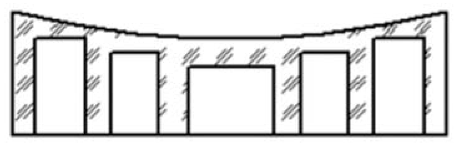
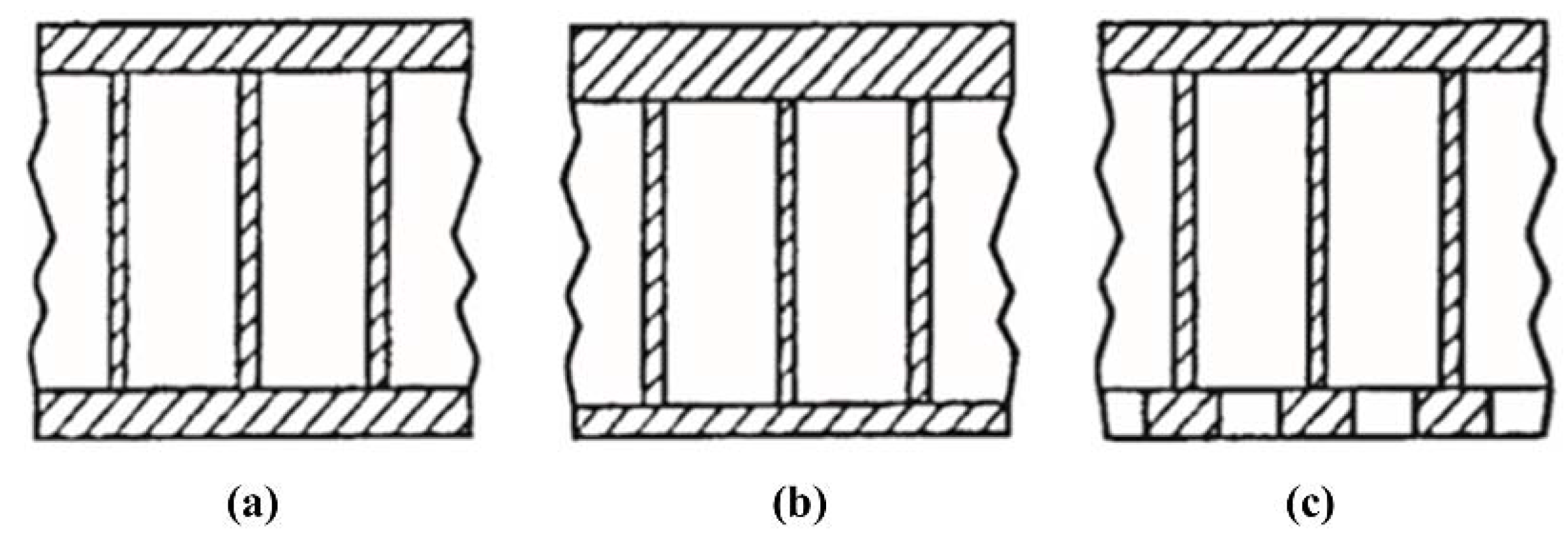
A mirror lightweighted with a cellular section is usually structurally more efficient than its equivalent-sized solid version. This type of design could be divided into two types, open-back, and sandwich mirrors, according to whether a back sheet exists. Open-back mirrors consist of a thin face sheet stiffened or reinforced with a regular arrangement of perpendicular ribs forming open pockets or cells in the back of the mirror, as shown in Figure 3. So the fabrication is usually less difficult than the more complex sandwich structure and the application is also more general [10,15].
Five common polygon core configurations are shown in the Figure 4 [16]. Trapezoidal pockets are generally used for circular mirrors with a central hole. Circular holes which have low lightweight ability could be regarded as the simplification of hexagonal pockets; however, the uneven spacings between circular cells negatively affect the structural stiffness of the mirror [17,18].
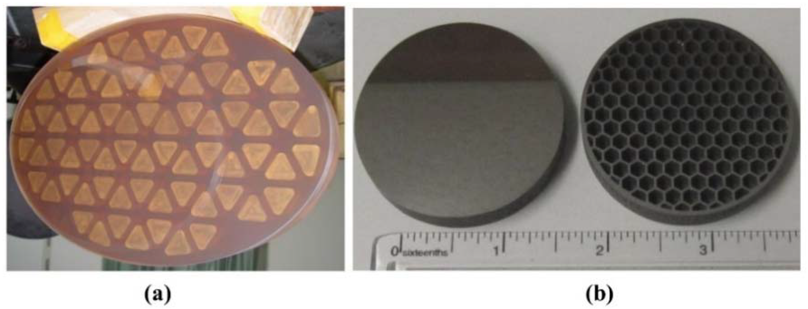
Considering the complexity of design and processing, triangular and hexagonal pockets are widely adopted in the lightweight design of mirrors. Here are two examples, below. Chen ya et al. designed the triangular cells scheme based on the oval planar reflector, and the lightweight rate of the lightweight reflector is 33% (Figure 5a) [15]. The team from Corning fabricated a small mirror with honeycombed lightweight structure by DMLS (Direct Metal Laser Sintering) in 2015 in Figure 5b [19]. There are multiple instructive studies about which of the two kinds of designs, triangular or hexagonal pockets, has better performance. So typical research and conclusions for this issue were listed to provide information on the relative merits of designs in Table 2.
2.3. Sandwich Cellular Mirrors
The sandwich mirror adds a back sheet compared to the open-back mirror, consisting of a core intercalated between two solid layers. The typical sections of sandwich mirrors are shown in Figure 6. They are traditionally produced by bonding plate material to a honeycomb core or using reaction-bonded technology in the mirror manufacturing industry [28]. Symmetry for a sandwich mirror means that the thickness of the face and back sheets are the same and that the inscribed circle diameter and rib thickness are constant. However, mirror performance is not improved with a non-symmetric design (Figure 6b), which is normally used to allow for more material removal during the grinding and polishing of the optical surface [10].
Wang Xiaoyong et al. [29] adopted the arch back thick honeycomb sandwich structure according to the technical requirements of the 1.3 m-caliber space mirror, as shown in Figure 7. The sandwich structure consists of a reflector, a base plate, and a sandwich layer. After optimizing optical processing and other processes, the developed reflector components have been analyzed by FEA (Finite Element Analysis), tested in a lab, and reached the technical requirements.
Carolyn Atkins et al. [30,31] aimed to investigate different AM materials and methods toward lightweight mirrors for space. The mirror lightweighted in the form of arches (Figure 8a) was printed commercially using metal laser sintering (MLS) in the aluminum alloy AlSi10Mg and was lightweighted to 44% of a solid equivalent. They compared the properties of a mechanical manufacturing honeycomb design with a 3D-printed lightweight design (arches) by FEA. The arch design was stiffer and showed fewer node displacements than the honeycomb design [32]. Accounting for the actual process properties of CFRP (Carbon Fiber Reinforced Plastic), Ding Jiaoteng et al. [33] formed mirror panels laminated based on thermal stability design for a Φ 300 mm CFRP mirror. Then, the honeycomb sandwich structure was fabricated using one innovative inlaying-grafting design method as shown in Figure 8b,c.
In the study of Enrico Hilpert et al. [34], a series of different mirror designs were investigated, including a full solid mirror, an empty shell model, and three different designs. Figure 9a shows the model which contains holes in a cross-directional pattern along the neutral plane and represents a lightweight design manufacturable by cutting techniques. The “honeycomb” mirror was developed (Figure 9c), which could only be manufacturable by AM. The inner part of the mirror consists of a hexagon (honeycomb) structure, with additional holes on all faces. Although the mass reduction of this design, 63.5%, is less than the honeycomb mirror (Figure 9b), it has a higher stiffness compared to other designs tested by FEA.
2.4. Summary
Table 3 summarizes typical conventional designs. The manufacture and installation of contoured-back solid mirrors are relatively easy; however, the weight reduction effect and deformation cannot be outstanding at the same time [10,35]. Mirrors lightweighted with a cellular section are usually structurally more efficient than their equivalent-sized solid version. Open-back lightweight mirrors display high effective weight loss, which is also more common because fabrication is always less difficult than the more complex sandwich structure. However, better structural performance is obtained with a sandwich scheme [18]. With the rapid development of AM technologies, it is possible to fabricate a closed-back sandwich mirror with a complex internal structure [36].
Polina A. Abdula et al. [41] have verified the above conclusion by comparing the performance of different designs. The team achieved a simulation and comparative study of the typical structures by diverse sorts of models as shown in Table 4. The parameters of the initial model are as follows:
Diameter, 1 m; Thickness, 0.15 m; Central screening, 20%; Material, Titanium; Surface type, Spherica.
3. Topology Optimization
Topology optimization technology is an advanced structural design method which can obtain the optimal structure configuration via reasonable material distribution satisfying specified load conditions, performance, and constraints [42]. Since the theoretical background of topology optimization was set by Bendsøe and Kikuchi in 1988, this technology has been developed rapidly [43]. With the increasing improvement of the lightweight ratio and performance of modern space optical systems, the traditional cellular designs gradually could not satisfy engineering requirements. The technology of topology optimization has played an important role and gained popularity in lightweight design studies with a conventional open-back or sandwich design as a baseline. With the advance of technology in AM, topologically optimized structures with complex geometric configurations could also be directly processed, which provides more possibilities for the non-conventional lightweight designs of space optical mirrors [44,45,46].
3.1. Topology Optimization with a Baseline
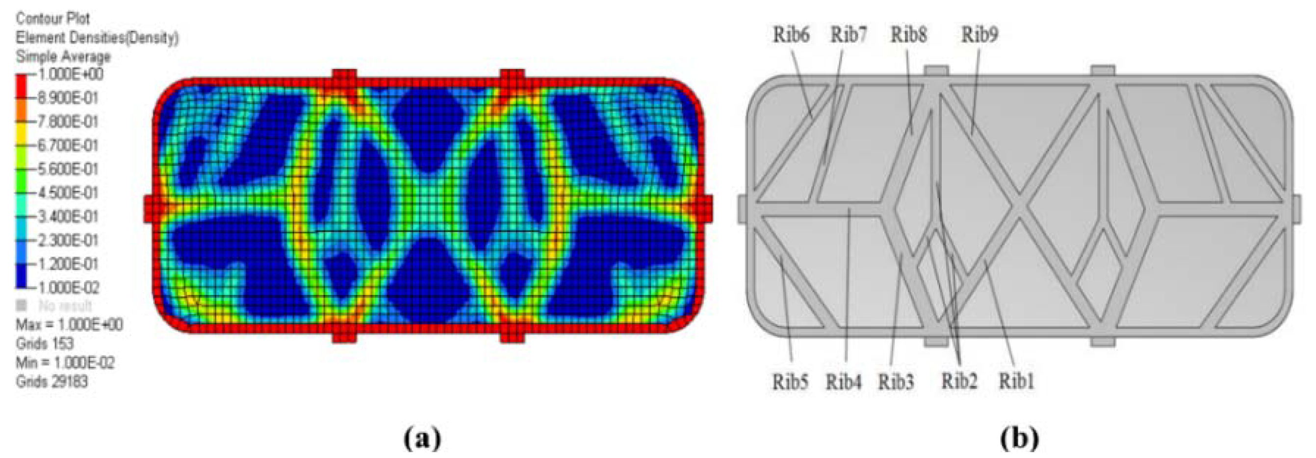
Liu Fengchang et al. [47] proposed a topology optimization method by using triangular polygon core configurations as the initial design. The lightweight ribs are grouped according to the optimal material distribution obtained from topology optimization (Figure 10). They used the compromise programming method to find a compromise solution because this design is a multi-objective optimization problem, such as the RMS value of the surface shape error, the total mass, and the eigen-frequency. The FEA results show that this design method is relatively effective.
Qu Yanjun et al. [48] optimized the horizontally placed mirror using six-point peripheral supports under the effect of gravity by OptiStruct. According to the topology optimization results in Figure 11a, they modified the initial structure and established a 3D model in Figure 11b. Through the above calculation and analysis, the ratio of lightweight, structure stiffness, and surface accuracy of the optimized rectangular mirror was superior to that of the traditional triangular lightening mirror.
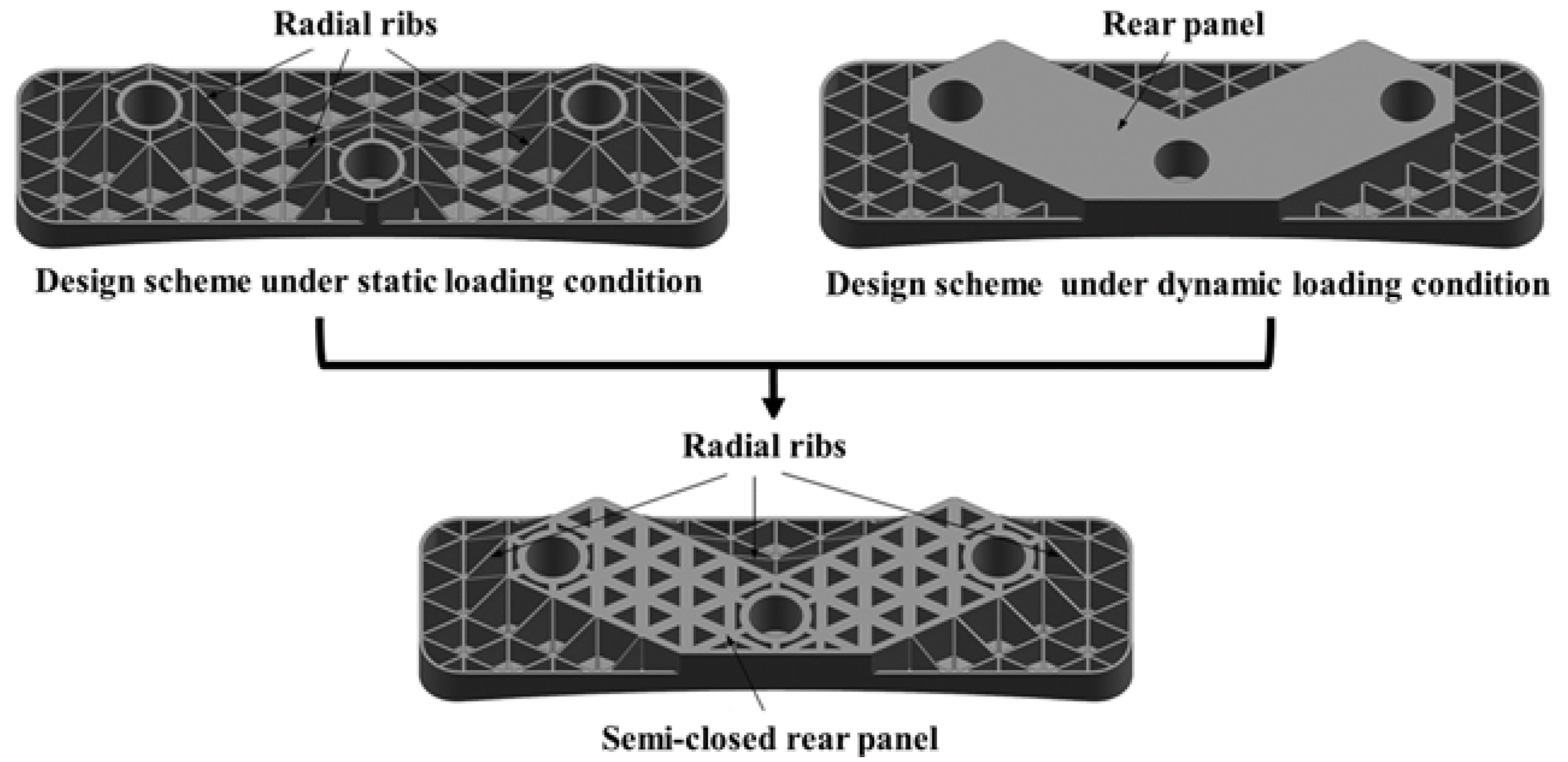
Li Yewen et al. [49] used the topology optimization method with variable density to obtain the mirror topology models with maximum stiffness and maximum first-order frequency respectively (Figure 12). The integrated design scheme of the mirror was obtained by synthesizing the two topology models. The result of FEA showed that the surface figure of the mirror after optimization has been significantly improved.
3.2. Direct Topology Optimization and Design
Harrison Herzog et al. [50] optimized the mirror using Altair Hyperworks with minimal surface displacement as a merit function. As shown in Figure 13a,b, two different models obtained, top mount and side mount, were optimized, processed, and tested in both aluminum and titanium, then, both of them can meet the needs of practical optical applications. Dong Deyi et al. [51] fabricated the lightweight 3D model established directly according to the topology optimization results, then, they used the method of density filtering to solve the problem of unsmooth structure. As shown in Figure 13c is the radial structure manufactured by selective laser melting (SLM) technology. The surface density and the mirror deformation under the self-weight of the mirror all met the requirements after tests in a lab.
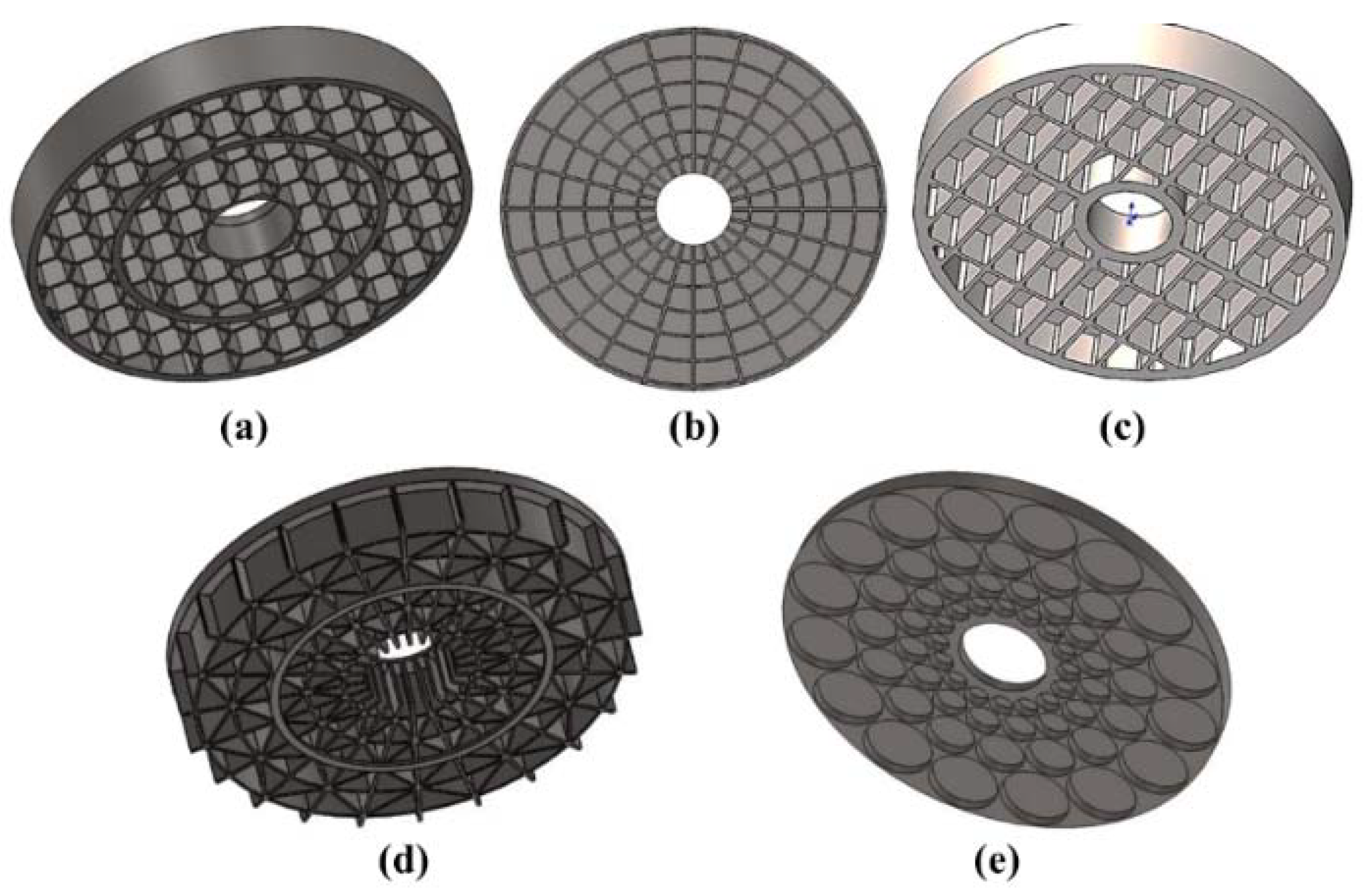
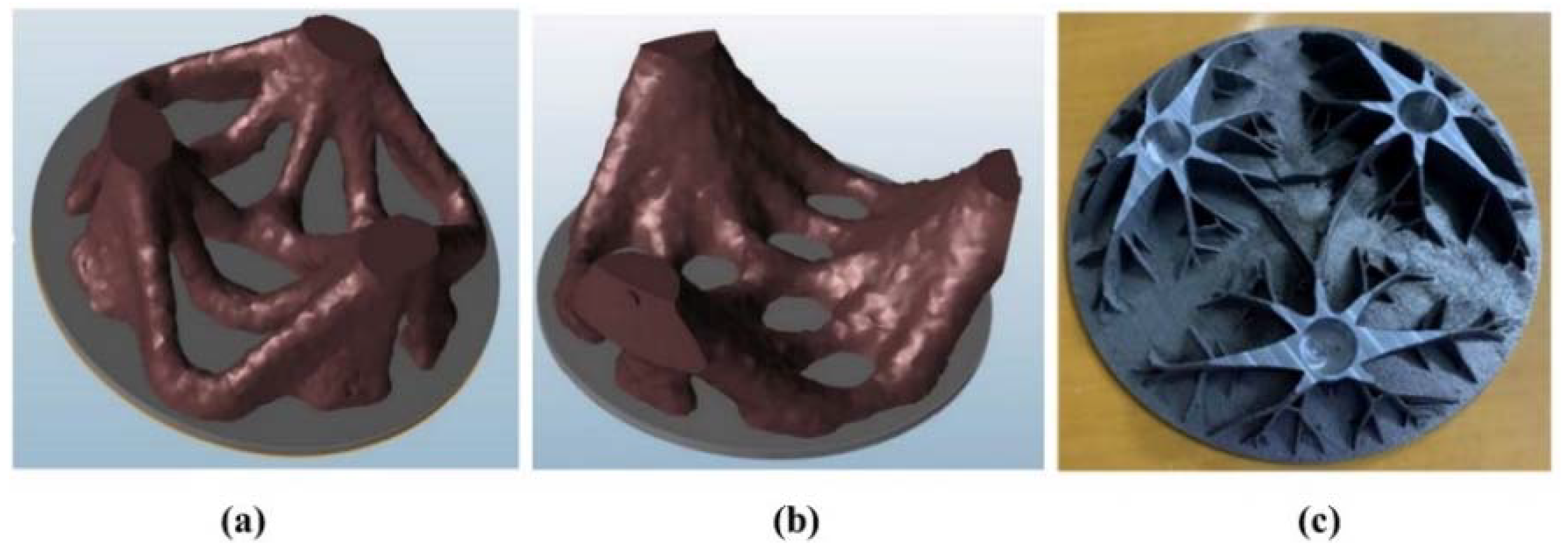
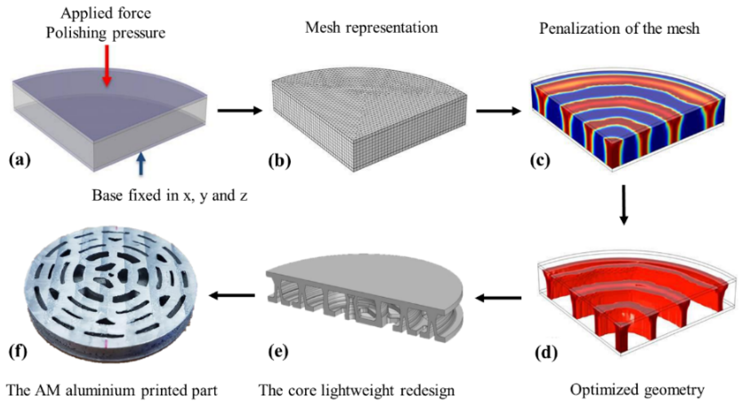
Carolyn Atkins et al. [30,31] designed the non-conventional lightweight mirror designs by the FEA tool topology optimization. Figure 14 shows the process of the design and after some detailed adjustments, the final optimized samples depicted in Figure 14e,f are a series of co-axial tapered rings radiating from a central pillar. The design did show better PV and RMS; however, the expected surface roughness figure was not achieved.
Table 5 summarizes typical topological optimization designs for space mirrors.
4. Non-Conventional Design
4.1. Foam Cores
For conventional lightweight mirrors (Section 2), the core mesh must be separated by distances large relative to their thickness, thereby allowing the mirror face sheet to sag between the webs during polishing forces or under the gravitational load. Mirrors with foam cores significantly improve these problems in several aspects. Due to the fact that a large percentage of open space (typically 90%) within the foam structure, a high lightweight ratio could also be realized. Goodman and Jacoby compared some characteristics of conventional webs and foam cores for mirrors, as indicated in Table 6 [53].
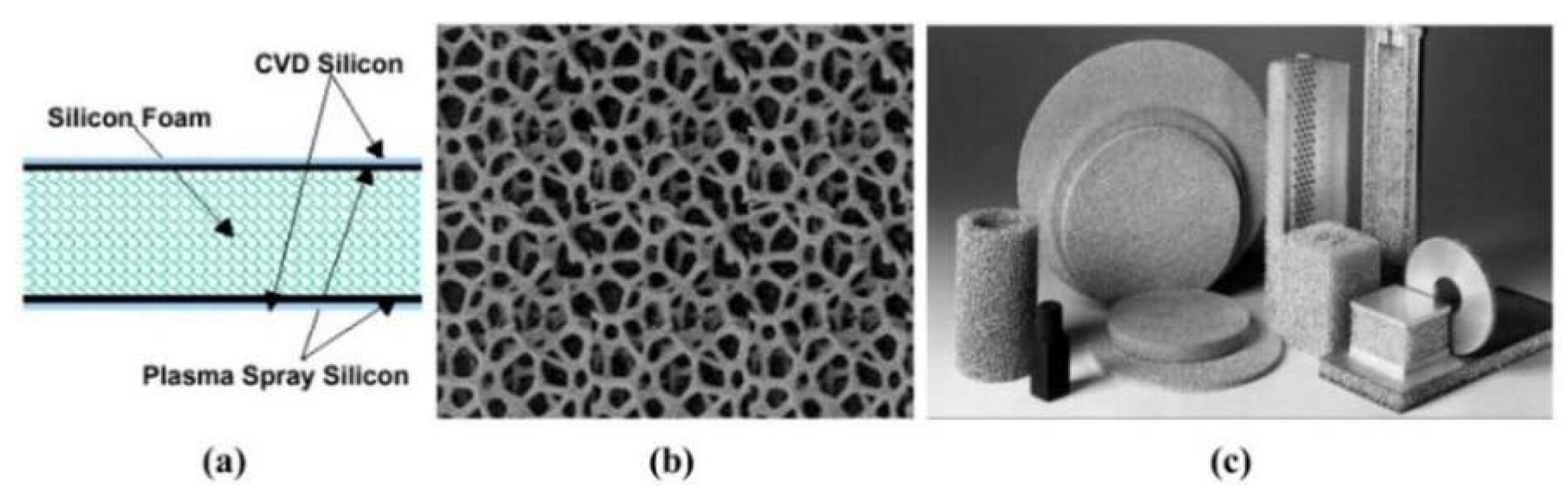
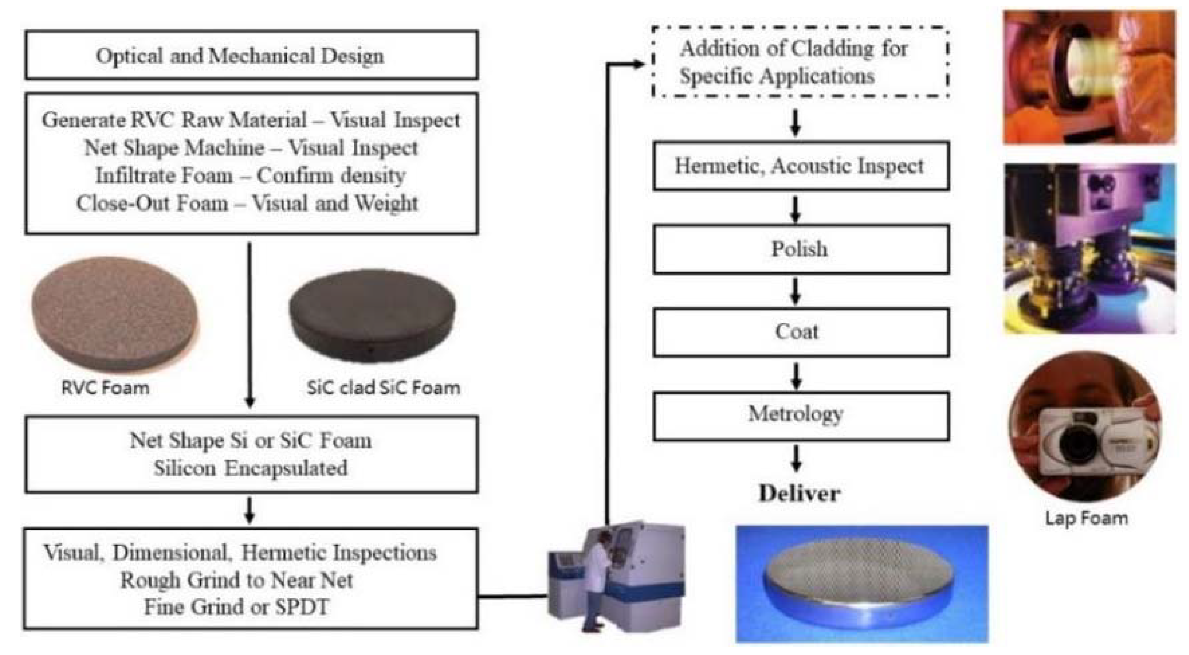
Goodman et al. [54,55,56,57] used silicon foam which can be machined to any shape (sphere, asphere, etc.) to manufacture the silicon lightweight mirror (SLM). The basic structure for a silicon foam composite optic is shown in Figure 15a and the basic elements of it are two silicon faceplates that are bonded to an open-cell silicon foam core. Then, they developed silicon and silicon carbide lightweight mirror systems (SLMSTM and SiC-SLMSTM). The manufacturing process of the SLMSTM described above is shown in Figure 16.
4.2. Lattices
For conventional methods of fabricating metallic cellular materials which allow for some control over pore shape and size, they remain limited to producing randomly organized structures. Additive manufacturing (AM), also known as 3D printing, manufactures parts via joining the material layer-by-layer. The layer-upon-layer methodology dramatically increases the design possibilities of non-conventional structures that exhibit complex structural configurations and the ease and speed by which fabrication occurs. This contrasts with AM which enables the creation of non-conventional structures with a predefined external geometry and internal architecture. In recent years, AM has shown an effective way of fabricating components with complex configurations, opening the possibility to manufacture complex lightweight structures for mirrors, especially for lattice and foam structures [58,59,60].
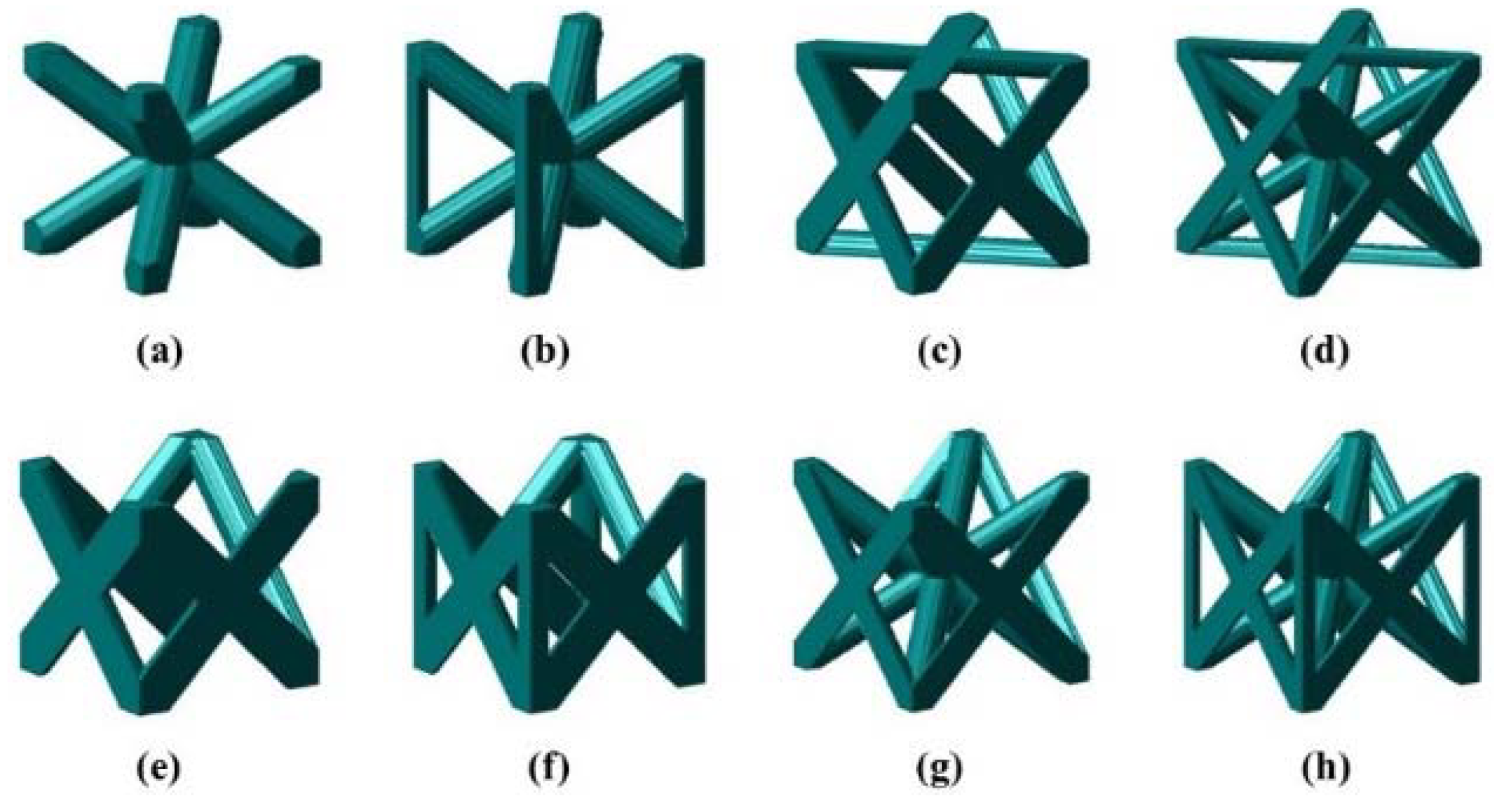
In the context of modeling for AM, a lattice is a set of points and line segments between the points embedded in the 3-dimensional space of the mirrors [61]. Lattice unit cells can be constructed using (a) strut-based members which are more widely used in optical mirror manufacturing or (b) surface-based representation. The nomenclature for the library of strut-based unit cells presented in Figure 17 are as follows: BCC is Body Cantered Cubic; BCCz is BCC with ‘z’ direction reinforcement; FCC is Face Centered Cubic; FBCC results from the union of FCC and BCC; names with ‘S’ prefix are self-supporting variants which have no members that lay parallel to the x-y plane [62]. From the existing research, the BCC lattice is adopted most concerning the stability of the space truss structure and design difficulty.
In 2021, Zhang Muyao et al. [63] introduced the BCC lattice structure into a small-diameter aluminum alloy mirror structure design, as shown in Figure 18. They topologically optimized the lattice structure based on the MIST method, and the cross-sectional area of the rod is taken as the optimization object. It is verified by FEA that the lightweight rate and surface accuracy requirements of the optimized reflector are better than those of the traditional lightweight form reflector.
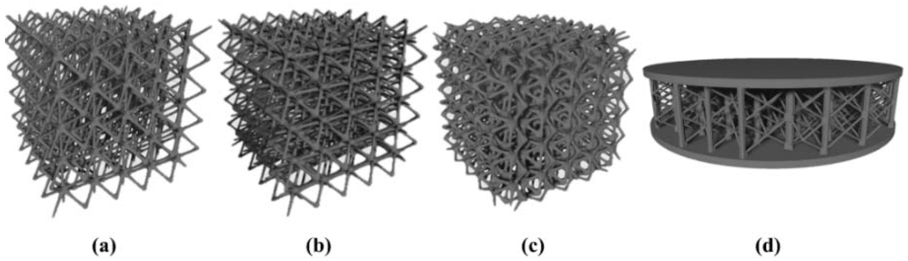
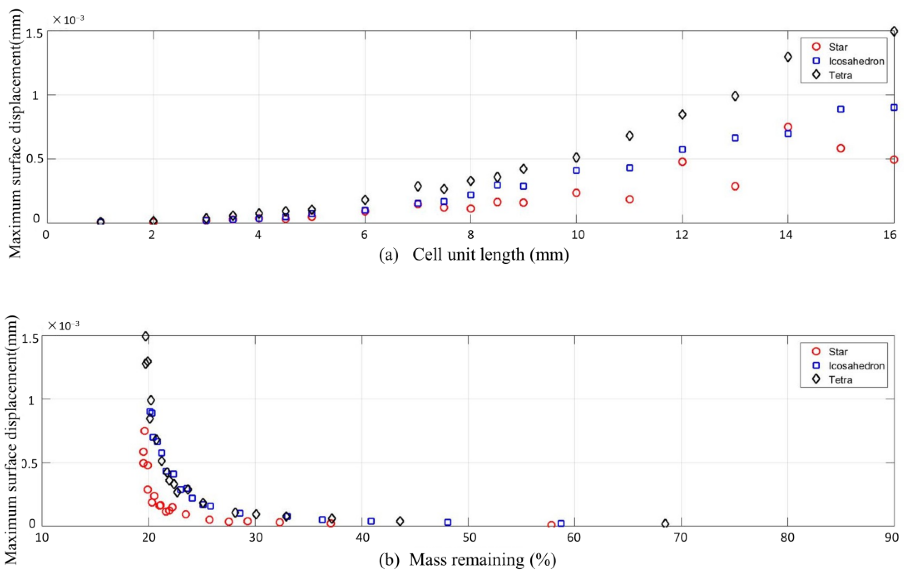
Carolyn Atkins et al. [64] selected three lattice structures which are Star (BCCz), Icosahedron, and Tetra, shown in Figure 19 for further study. The two plots in Figure 20 show that the star lattice exhibits the minimum change in displacement with cell length and presents a clear reduction in weight for given displacement in relation to the other lattices. Then, they optimized the Star lattice by two properties, the length of the unit cell and the threshold value of the optimization, in NetFabb. Figure 19d depicts the optimum Star lattice.
4.3. Voronoi Cells
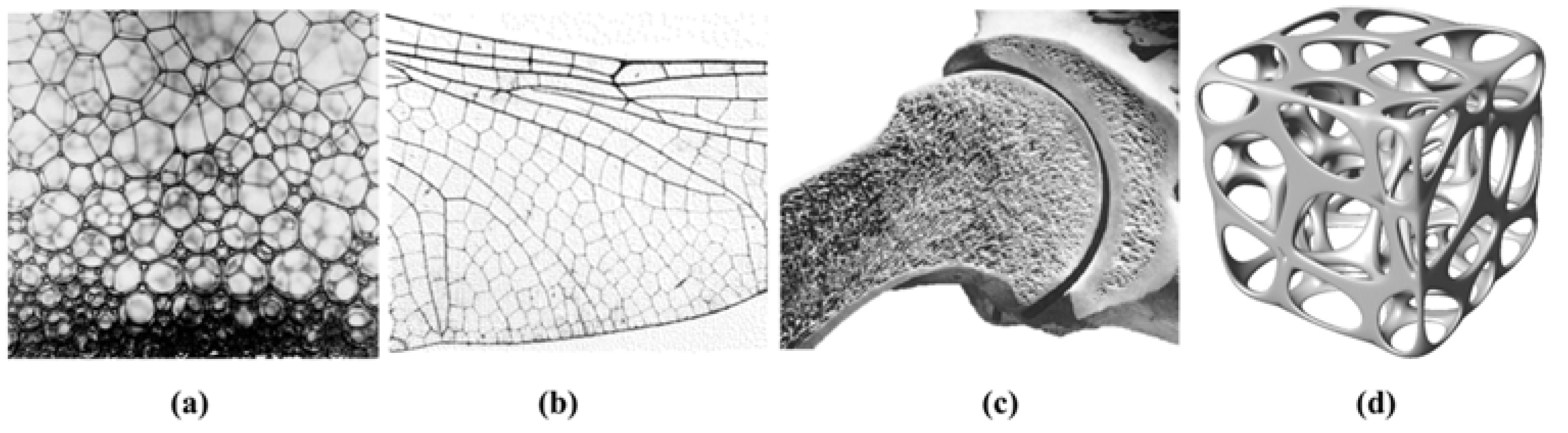
Over millions of years of natural evolution, nature has developed extensive high-performance structures, and Voronoi structure or Voronoi media exists widely in nature (Figure 21a–c) [5,65]. For example, Voronoi scaffolds shown in Figure 21d are inspired by bone. Ref. [66] Voronoi tessellation is a space division technique developed by mathematician G.F.Voronoi in 1905. This method produces regions called “cells” from a set of points called “seeds”, and it has the characteristic property that any point within a cell will be closer to the cell’s seed than any other point in the space [67,68]. Voronoi cells offer an element of randomization in the structure which is the primary difference between the lattices and Voronoi cells. If the seeds were distributed in a regular pattern, a Voronoi pattern would be a regular grid structure. However, a random Voronoi structure can be obtained by adding a random component to the seed placement, which has unique advantages and characteristics different from other structures.
Previous scholars have found that Voronoi structures perform excellently in mirror design. As shown in Table 7, in the research of Joni Mici et al. [61], Voronoi designs achieved the greatest volume loss among eight schemes. Meanwhile, Voronoi mirrors showed significant improvements, compared with the traditional design, in thermal displacement, thermal strain, and displacement under pressure. Furthermore, Voronoi structures provide more degrees of freedom for structural optimization so the optimized design can achieve better performance [34].
Voronoi can be divided into 2D and 3D manufacturing types according to the spatial distribution. A 3D-Voronoi structure, which could be regarded as a similar foam core structure (Section 4.1), could own similar advantages. At the same time, a 3D-Voronoi structure can be controlled and adjusted by algorithms instead of completely random foam so it’s more suitable for engineering applications.
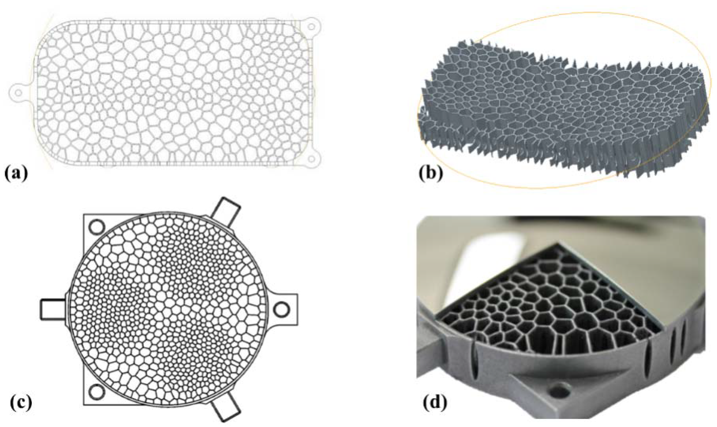
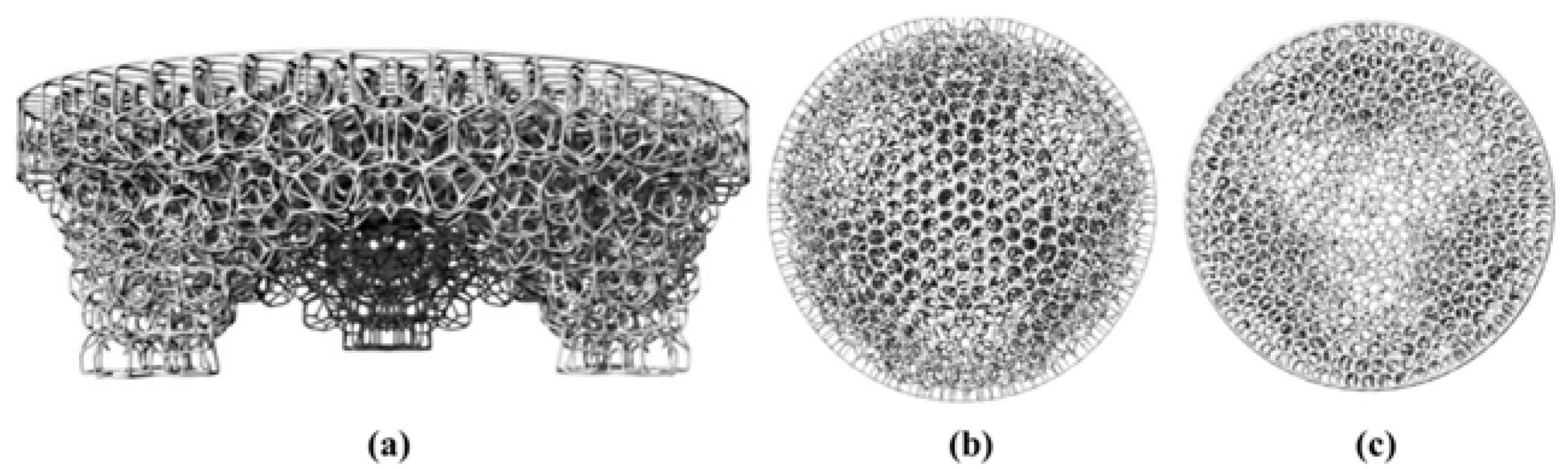
Enrico Hilpert et al. [69,70,71] from Fraunhofer Institute, systematically studied the mirrors filled with a stochastic 2D-Voronoi foam. As shown in Figure 22a,b the density distribution of the foam is based on static load cases. As shown in Figure 22c Voronoi cells from Poisson disk sampling for the nearest-neighbor distance, which assumes smaller minimal values than in the surrounding area in the three areas. As a result, the mass could be reduced significantly, meanwhile, the stiffness is increased, resulting in a significant increase in the specific stiffness.
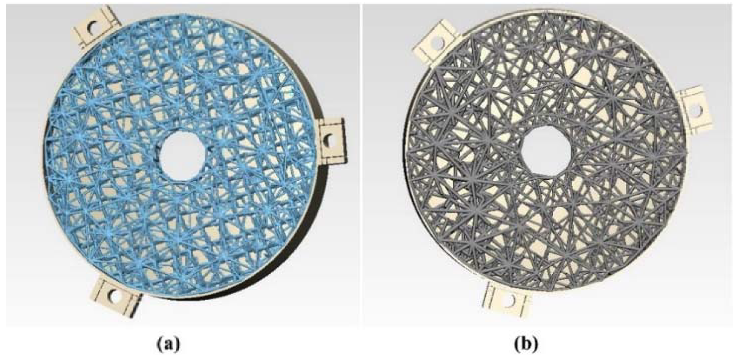
Figure 23a shows an open 3D-Voronoi structure with 1000 points generated using Lloyd’s algorithm [72] inside of the topology-optimized mirror shape [61]. Changing the number of cells (structural members) as well as the size of the structural members will affect stiffness under load. Thermal variations under operational loads during processing could also alter structural properties. The follow-up research on these 3D-Voronoi structures ought to be continued, which will promote the innovation of the mirror design.
5. Future Trends
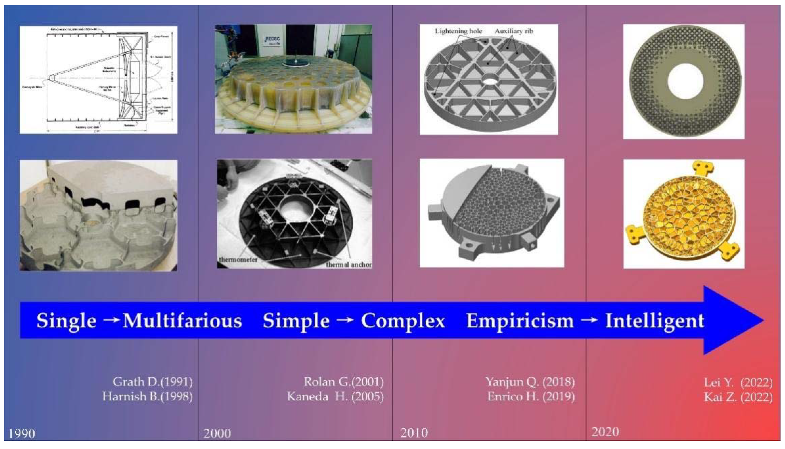
As we all know, the designing and manufacturing criteria for space mirrors are lightweight and high stiffness. The traditional lightweight mirror structures of web and arch design have played an important role in the past decades and have been widely used. With the development of the aerospace industry and the improvement of relevant technical requirements of space optical systems, a variety of design and optimization methods have been applied to the field of lightweight design for mirror core structures. In recent years, especially after the rapid development of metal 3D printing, irregular structures, represented by lattice and Voronoi, which show multifaced outstanding performance and greatly increase the freedom of mirror design, will play an important role in the future [5]. Looking back at the development history of the recent dozens of lightweight design and optimization of space mirrors (Figure 24), the design level has been continuously improved while the manufacturing technology has been constantly iterative so that innovative structures have been continuously manufactured with complex surface shapes and complex mechanical geometric shapes, which are characterized by lightweight, high strength/stiffness relative to weight and aesthetics.
Therefore, future work and trends of optimizing the design of reduced-weight mirrors may focus on the following four topics:
- (1)
- Explore and develop the application of 3D printing in the field of mirror manufacturing, including extending the usable materials, perfecting the printing technology to enable the fabrication of more refined bio-inspired structures, etc. With the rapid development of this technology, the mirror with complex geometries could be manufactured successfully [77]. The future priorities to introduce AM-made mirrors are developing a reliable and traceable process chain from design and development via manufacturing, post-processing, assembly, and integration to verification and final inspection [78,79].
- (2)
- Topology optimization technology will continue to play an important role in the field of lightweight mirror design. Especially for mirrors manufactured by AM, they will be occasionally affected by process parameters, material properties, and structures during processing. Future related research will endeavor to develop an effective model to accurately predict product performance and simulate a more accurate polishing, or diamond turning, environment with the intention to realize the integrated design of the material, process, structure, and performance [31,44].
- (3)
- Lattice and Voronoi, unconventional structures realized by 3D printing technology, show excellent weight reduction and mechanical properties, will become a significant direction with a good development prospect. It’s a promising idea to use the combination of topology optimization, lattice, and other methods to improve structures synergistically, then reasonable tools and indicators should be used to verify the structural performance. Mirrors with complex structures are limited by some factors, such as the accuracy of AM, lack of mature structural algorithms, and tough post-processing, which will be a promising issue and possess extensive engineering application prospects [79].
- (4)
- Scientific and technological problems can be solved via the investigation of natural structures and materials. For example, the honeycomb structure, constantly used in lightweight mirrors, is inspired by the bee honeycomb. Biomimicry can be used to improve mirror structures by learning naturally excellent structures. Artificial intelligence (AI) and machine learning could also facilitate the design of bio-inspired structures [80].
6. Conclusions
The present review introduces a series of advances in the structural design of space mirrors mainly including traditional machining structural design, topology optimization, and special designs such as lattices and Voronoi structures. Meanwhile, the application and performance of different designs are compared for reference. With the continuous development of design technologies and AM, more mirrors with innovative structures and excellent performance will be put into practical engineering applications in the future.
Author Contributions
Conceptualization, C.Z. and Z.L.; methodology, C.Z. and Z.L.; investigation, C.Z. and Z.L.; writing—original draft preparation, C.Z.; writing—review and editing, Z.L.; supervision, Z.L. All authors have read and agreed to the published version of the manuscript.
Funding
This research was funded by the Foundation of Key Laboratory of Space-based Dynamic and Rapid Optical Imaging Technology, Chinese Academy of Sciences, grant number CXJJ-21S040.
Institutional Review Board Statement
Not applicable.
Informed Consent Statement
Not applicable.
Data Availability Statement
All data in this review are available in the documents referenced in bibliography.
Conflicts of Interest
The authors declare no conflict of interest.
References
- Liu, R.; Li, Z.; Xu, W.; Yang, X.; Zhang, D.; Yao, Z.; Yang, K. Dynamic Analysis and Experiment of a Space Mirror Based on a Linear State Space Expression. Appl. Sci. 2021, 11, 5379. [Google Scholar] [CrossRef]
- Li, Y.; Li, Z.; Yong, Q.; Wang, T.; Zhang, D. Design of athermalized mounting structure for the sub-aperture primary mirror of a synthetic aperture telescope. Adv. Mech. Eng. 2022, 14, 16878140211067044. [Google Scholar] [CrossRef]
- Chen, Y.C.; Huang, B.K.; You, Z.T.; Chan, C.Y.; Huang, T.M. Optimization of lightweight structure and supporting bipod flexure for a space mirror. Appl. Opt. 2016, 55, 10382–10391. [Google Scholar] [CrossRef]
- Dournaux, J.L.; Consortium, C.T.A. Application of the topography optimization technique to the design of a lightweight primary mirror for the GCT, a dual-mirror telescope proposed for the Cherenkov Telescope Array. In Proceedings of the Conference on Advances in Optical and Mechanical Technologies for Telescopes and Instrumentation III, Austin, TX, USA, 10–15 June 2018. [Google Scholar]
- Zhang, K.; Qu, H.; Guan, H.; Zhang, J.; Zhang, X.; Xie, X.; Yan, L.; Wang, C. Design and fabrication technology of metal mirrors based on additive manufacturing: A review. Appl. Sci. 2021, 11, 10630. [Google Scholar] [CrossRef]
- Liu, F.; Li, W.; Zhao, W.; Wang, X.; Wang, X. Fast Optimization Design of the Flexure for a Space Mirror Based on Mesh Deformation. Photonics 2021, 8, 567. [Google Scholar] [CrossRef]
- Roulet, M.; Atkins, C.; Hugot, E.; Snell, R.; van de Vorst, B.; Morris, K.; Marcos, M.; Todd, I.; Miller, C.; Dufils, J. Use of 3D printing in astronomical mirror fabrication. In Proceedings of the 3D Printed Optics and Additive Photonic Manufacturing II, Online Event, 6–10 April 2020; pp. 33–44. [Google Scholar]
- Yan, L.; Zhang, X.; Fu, Q.; Wang, L.; Shi, G.; Tan, S.; Zhang, K.; Liu, M. Assembly-level topology optimization and additive manufacturing of aluminum alloy primary mirrors. Opt. Express 2022, 30, 6258–6273. [Google Scholar] [CrossRef]
- Zhang, K.; Xie, X.; Wang, C.; Wang, H.; Xu, F.; Wang, H.; Zhang, X.; Guan, H.; Qu, H.; Zhang, J. Optomechanical Performances of Advanced Lightweight Mirrors Based on Additive Manufacturing. Micromachines 2022, 13, 1334. [Google Scholar] [CrossRef]
- Yoder, P.; Vukobratovich, D. Opto-Mechanical Systems Design; CRC Press: Boca Raton, FL, USA, 2015. [Google Scholar]
- Moon, I.K.; Han, I.; Chang, B.S.; Kim, H.K.; Cho, M.K. Design study of a KAO telescope with a 1-m double arch primary mirror. In Proceedings of the Conference on Optomechanical and Precision Instrument Design, San Diego, CA, USA, 10–11 July 1995; pp. 154–166. [Google Scholar]
- Werner, M. The Spitzer Space Telescope. Opt. Eng. 2012, 51, 011008. [Google Scholar] [CrossRef]
- Yoder, P.R. Mounting Optics in Optical Instruments, 2nd ed.; SPIE Press: Bellingham, WA, USA, 2008. [Google Scholar]
- Pearson, E. Thin mirror support systems. In Optical Infrared Telescopes for the 1990s; Kitt Peak National Observatory: Tucson, AZ, USA, 1980; p. 555. [Google Scholar]
- Chen, Y.; Xie, J. Manufacturing technology of lightweight mirror for space optics. In Proceedings of the 6th International Symposium on Advanced Optical Manufacturing and Testing Technologies: Advanced Optical Manufacturing Technologies; 2012; pp. 185–190. [Google Scholar]
- Abdula, P.A.; Tolstoba, N.D. Comparing and analysis of design lightweight large mirrors for space basing. In Optical Modelling and Design IV; SPIE: Bellingham, WA, USA, 2016. [Google Scholar]
- Fruit, M.; Antoine, P.; Varin, J.L. Development of the SOFIA silicon carbide secondary mirror. In Proceedings of the Conference on Airborne Telescope Systems II, Waikoloa, HI, USA, 27–28 August 2002; pp. 274–285. [Google Scholar]
- Valente, T.M.; Vukobratovich, D. A Comparison of the Merits of Open-Back, Symmetric Sandwich and Contoured Back Mirrors as Light-Weighted Optics. In Precision Engineering and Optomechanics; SPIE: Bellingham, WA, USA, 1989; pp. 20–36. [Google Scholar]
- Woodard, K.S.; Myrick, B.H. Progress on High-Performance Rapid Prototype Aluminum Mirrors. In Proceedings of the Conference on Advanced Optics for Defense Applications—UV through LWIR II, Anaheim, CA, USA, 9–10 April 2017. [Google Scholar]
- Barnes, W.P. Hexagonal vs. Triangular Core Lightweight Mirror Structures. Appl. Opt. 1972, 11, 2748–2751. [Google Scholar] [CrossRef]
- Richard, R.M.; Malvick, A.J. Comment on: Hexagonal vs. Triangular Core Lightweight Mirror Structures. Appl. Opt. 1973, 12, 893. [Google Scholar] [CrossRef]
- Sheng, S.C.F. Lightweight mirror structures best core shapes—A reversal of historical belief. Appl. Opt. 1988, 27, 354–359. [Google Scholar] [CrossRef] [PubMed]
- Richard, R.M.; Malvick, A.J. Elastic deformation of lightweight mirrors. Appl. Opt. 1973, 12, 1220–1226. [Google Scholar] [CrossRef] [PubMed]
- Barnes, W.P. Lightweight mirror structures best core shapes: A reversal of historical belief; comment. Appl. Opt. 1988, 27, 354–359. [Google Scholar] [CrossRef] [PubMed]
- Sheng, S.C.F. Lightweight mirror structures best core shapes—A reversal of historical belief: Author’s reply to comment. Appl. Opt. 1988, 27, 216. [Google Scholar] [CrossRef]
- Yu, K.; Zhang, C.; Cao, Y.; Liu, R. Hole Element Design of Honeycomb Elliptical Mirror. J. Chin. Soc. Astronaut. 2010, 31, 1475–1481. [Google Scholar]
- Shah, U.B.; Kapania, R.K. Failure of Hexagonal and Triangular Honeycomb Core Sandwich Panels. AIAA J. 2020, 58, 4923–4940. [Google Scholar] [CrossRef]
- Chen, X.A.; Cheng, Y.T.; Zeng, Q.N.; Liu, H.; Fang, J.Z.; Rao, C.H. Optimized Analysis of Geometry Parameters for Honeycomb Sandwich Mirror. In Proceedings of the Conference on Advances in Optical and Mechanical Technologies for Telescopes and Instrumentation, Montreal, QC, Canada, 23–27 June 2014. [Google Scholar]
- Wang, X.; Guo, C.; Liu, Y.; Chen, J.; Wang, Y.; Hu, Y. Design and manufacture of 1.3 meter large caliber light-weighted Space optical components. In Proceedings of the International Conference on Space Optics—ICSO 2018, Chania, Greece, 9–12 October 2019; pp. 304–321. [Google Scholar]
- Atkins, C.; Feldman, C.; Brooks, D.; Watson, S.; Cochrane, W.; Roulet, M.; Doel, P.; Willingale, R.; Hugot, E. Additive manufactured X-ray optics for astronomy. In Proceedings of the Conference on Optics for EUV, X-ray and Gamma-Ray Astronomy VIII, San Diego, CA, USA, 8–10 August 2017. [Google Scholar]
- Atkins, C.; Feldman, C.; Brooks, D.; Watson, S.; Cochrane, W.; Roulet, M.; Hugot, E.; Beardsley, M.; Harris, M.; Spindloe, C. Topological design of lightweight additively manufactured mirrors for space. In Advances in Optical and Mechanical Technologies for Telescopes and Instrumentation III; SPIE: Bellingham, WA, USA, 2018; pp. 123–139. [Google Scholar]
- Roulet, M.; Atkins, C.; Hugot, E.; Lemared, S.; Lombardo, S.; Ferrari, M. 3D printing for astronomical mirrors. In Proceedings of the Conference on 3D Printed Optics and Additive Photonic Manufacturing, Strasbourg, France, 23–24 April 2018. [Google Scholar]
- Ding, J.T.; Xu, L.; Ma, Z.; Xie, Y.J.; Luo, Y.; Wang, Y.J.; Pang, Z.H. The Lightweight Structure Design of a CFRP Mirror. In Proceedings of the 8th International Symposium on Advanced Optical Manufacturing and Testing Technologies—Advanced Optical Manufacturing Technologies, Suzhou, China, 26–29 April 2016. [Google Scholar]
- Hilpert, E.; Hartung, J.; Risse, S.; Eberhardt, R.; Tünnermann, A. Precision manufacturing of a lightweight mirror body made by selective laser melting. Precis. Eng. 2018, 53, 310–317. [Google Scholar] [CrossRef] [Green Version]
- Schwertz, K.; Burge, J.H. Field Guide to Optomechanical Design and Analysis; Society of Photo-Optical Instrumentation Engineers (SPIE): Bellingham, WA, USA, 2012. [Google Scholar]
- Hu, R.; Chen, W.J.; Li, Q.H.; Liu, S.T.; Zhou, P.; Dong, Z.G.; Kang, R.K. Design Optimization Method for Additive Manufacturing of the Primary Mirror of a Large-Aperture Space Telescope. J. Aerosp. Eng. 2017, 30, 04016093. [Google Scholar] [CrossRef]
- Zhang, D.; Li, W.; Lv, Q.; Liu, Y.; Chen, X. Lightweight design and finite element analysis of primary mirror for the space telescope. In Proceedings of the Optical Systems Design 2015: Optical Design and Engineering VI, Jena, Germany, 7–10 September 2015; pp. 632–638. [Google Scholar]
- Zhou, H.; Zhang, C.-R.; Cao, Y.-B.; Zhou, X.-G. Lightweight C/SiC mirrors for space application. In Proceedings of the 2nd International Symposium on Advanced Optical Manufacturing and Testing Technologies: Large Mirrors and Telescopes, Xian, China, 2–5 November 2005; pp. 169–174. [Google Scholar]
- Wührer, C.; Kühl, C.; Lucarelli, S.; Bode, M. MERLIN: Overview of the design status of the lidar Instrument. In Proceedings of the International Conference on Space Optics—ICSO 2018, Chania, Greece, 9–12 October 2018; pp. 839–851. [Google Scholar]
- Geyl, R.; Ruch, E. Progress in ultra-lightweight glass ceramic space optics. In Proceedings of the International Conference on Space Optics—ICSO 2020, Virutal Event, 30 March–2 April 2021; pp. 79–89. [Google Scholar]
- Abdula, P.A.; Neutov, M.Y.; Tolstoba, N.D. Simulation and analysis of lightweight space mirror design. In Proceedings of the Conference on Modeling Aspects in Optical Metrology V, Munich, Germany, 23–25 June 2015. [Google Scholar]
- Sigmund, O.; Maute, K. Topology optimization approaches. Struct. Multidiscip. Optim. 2013, 48, 1031–1055. [Google Scholar] [CrossRef]
- Bendsøe, M.; Kikuchi, N. Generating optimal topologies in structural design using a homogenization method. Comput. Methods Appl. Mech. Eng. 1988, 71, 197–224. [Google Scholar] [CrossRef]
- Jihong, Z.; Han, Z.; Chuang, W.; Lu, Z.; Shangqin, Y.; Zhang, W. A review of topology optimization for additive manufacturing: Status and challenges. Chin. J. Aeronaut. 2021, 34, 91–110. [Google Scholar]
- Mutters, D.K. Mirror topology optimization. In Proceedings of the Optomechanical Engineering Conference, San Diego, CA, USA, 14 August 2019. [Google Scholar]
- Park, K.S.; Lee, J.H.; Youn, S.K. Lightweight mirror design method using topology optimization. Opt. Eng. 2005, 44, 053002. [Google Scholar]
- Liu, F.; Li, W.; Zhao, W.; Zhao, H.; Lin, G.; Wang, X. Topology Optimization Based Parametric Design of Balloon Borne Telescope’s Primary Mirror. Appl. Sci. 2021, 11, 5077. [Google Scholar] [CrossRef]
- Qu, Y.; Wang, W.; Liu, B.; Li, X. Topology optimization design of space rectangular mirror. In Proceedings of the Advanced Optical Design and Manufacturing Technology and Astronomical Telescopes and Instrumentation, Beijing, China, 9–11 May 2016. [Google Scholar]
- Li, Y.; Li, Z.; Liu, R.; Song, W.; Zhang, L. Integrated optimization design of rectangular mirror for space optical remote sensor. Sci. Technol. Eng. 2019, 19, 7. [Google Scholar]
- Herzog, H.; Segal, J.; Smith, J.; Bates, R.; Calis, J.; De La Torre, A.; Kim, D.W.; Mici, J.; Mireles, J.; Stubbs, D.M.; et al. Optical fabrication of lightweighted 3D printed mirrors. In Proceedings of the Conference on Optomechanical Engineering, San Diego, CA, USA, 10–12 August 2015. [Google Scholar]
- Fan, Y.C.; Dong, D.Y.; Li, C.; Sun, Y.X.; Zhang, Z.Y.; Wu, F.L.; Yang, L.W.; Li, Q.H.; Guan, Y.J. Research and Experimental Verification on Topology-Optimization Design Method of Space Mirror Based on Additive-Manufacturing Technology. Machines 2021, 9, 354. [Google Scholar] [CrossRef]
- Liu, G.; Liang, G.; Wang, X.; Wu, Q. Topology and parametric optimization based lightweight design of a space reflective mirror. Opt. Eng. 2018, 57, 1. [Google Scholar] [CrossRef]
- Goodman, W.A.; Jacoby, M.T. Dimensionally stable ultralightweight silicon optics for both cryogenic and high-energy laser applications. In Optomechanical Engineering 2000; SPIE: Bellingham, WA, USA, 2001; Volume 4198, pp. 260–270. [Google Scholar]
- Goodman, W.A.; Jacoby, M.T. Lightweight athermal SLMS innovative telescope. In Proceedings of the Space Systems Engineering and Optical Alignment Mechanisms, Denver, CO, USA, 4–6 August 2004; pp. 72–82. [Google Scholar]
- Jacoby, M.T.; Goodman, W.A. Material properties of silicon and silicon carbide foams. In Optical Materials and Structures Technologies II; SPIE: Bellingham, WA, USA, 2005; pp. 159–170. [Google Scholar]
- Jacoby, M.T.; Goodman, W.A.; Content, D.A. Results for silicon lightweight mirrors (SLMS). In Proceedings of the Optical Manufacturing and Testing IV; 2001; pp. 67–76. [Google Scholar]
- Jacoby, M.T.; Montgomery, E.E., IV; Fortini, A.J.; Goodman, W.A. Design, fabrication, and testing of lightweight silicon mirrors. In Proceedings of the Optomechanical Engineering and Vibration Control, Denver, CO, USA, 20–23 July 1999; pp. 460–467. [Google Scholar]
- Blakey-Milner, B.; Gradl, P.; Snedden, G.; Brooks, M.; Pitot, J.; Lopez, E.; Leary, M.; Berto, F.; du Plessis, A. Metal additive manufacturing in aerospace: A review. Mater. Des. 2021, 209, 110008. [Google Scholar] [CrossRef]
- Moghaddam, A.O.; Shaburova, N.A.; Samodurova, M.N.; Abdollahzadeh, A.; Trofimov, E.A. Additive manufacturing of high entropy alloys: A practical review. J. Mater. Sci. Technol. 2021, 32, 131–162. [Google Scholar] [CrossRef]
- Sanaei, N.; Fatemi, A. Defects in Additive Manufactured Metals and Their Effect on Fatigue Performance: A State-of-the-Art Review. Prog. Mater. Sci. 2020, 117, 100724. [Google Scholar] [CrossRef]
- Mici, J.; Rothenberg, B.; Brisson, E.; Wicks, S.; Stubbs, D.M. Optomechanical performance of 3D-printed mirrors with embedded cooling channels and substructures. In Optomechanical Engineering 2015; SPIE: Bellingham, WA, USA, 2015; pp. 30–43. [Google Scholar]
- Panesar, A.; Abdi, M.; Hickman, D.; Ashcroft, I. Strategies for functionally graded lattice structures derived using topology optimisation for additive manufacturing. Addit. Manuf. 2018, 19, 81–94. [Google Scholar] [CrossRef]
- Zhang, M.; Su, Y.; Wang, C. A Non-uniform Lattice Structure Size Optimization Design Based on Space Mirror. Spacecr. Recovery Remote Sens. 2021, 42, 123–129. [Google Scholar]
- Atkins, C.; Brzozowski, W.; Dobson, N.; Milanova, M.; Todd, S.; Pearson, D.; Bourgenot, C.; Brooks, D.; Snell, R.; Sun, W. Lightweighting design optimisation for additively manufactured mirrors. In Proceedings of the Astronomical Optics: Design, Manufacture and Test of Space and Ground Systems II, San Diego, CA, USA, 12–15 August 2019; pp. 353–371. [Google Scholar]
- Pearce, P. Structure in Nature is a Strategy for Design; MIT Press: Cambridge, MA, USA, 1978. [Google Scholar]
- Gómez, S.; Vlad, M.D.; López, J.; Fernández, E. Design and properties of 3D scaffolds for bone tissue engineering. Acta Biomater. 2016, 42, 341–350. [Google Scholar] [CrossRef] [PubMed]
- Abdullahi, H.S.; Gao, S. A novel multi-cell square tubal structure based on Voronoi tessellation for enhanced crashworthiness. Thin-Walled Struct. 2020, 150, 106690. [Google Scholar] [CrossRef]
- Abdullahi, H.S.; Liang, Y.; Gao, S. Predicting the elastic properties of closed-cell aluminum foams: A mesoscopic geometric modeling approach. SN Appl. Sci. 2019, 1, 380. [Google Scholar] [CrossRef] [Green Version]
- Heidler, N.; Hilpert, E.; Hartung, J.; von Lukowicz, H.; Damm, C.; Peschel, T.; Risse, S. Additive manufacturing of metal mirrors for TMA telescope. In Proceedings of the Conference on Optical Fabrication, Testing and Metrology VI, Frankfurt, Germany, 15–17 May 2018. [Google Scholar]
- Hilpert, E.; Hartung, J.; von Lukowicz, H.; Herffurth, T.; Heidler, N. Design, additive manufacturing, processing and characterization of metal mirror made of aluminum silicon alloy for space applications. Opt. Eng. 2019, 58, 092613. [Google Scholar] [CrossRef]
- Von Lukowicz, H.; Hartung, J.; Hilpert, E.; Damm, C.; Peschel, T.; Heidler, N. Optimization and additive manufacturing of a three-mirror-anastigmatic telescope. In Proceedings of the International Conference on Space Optics—ICSO 2020, Virtual Event, 30 March–2 April 2021; pp. 67–78. [Google Scholar]
- Lloyd, S.P. Least Squares Quantization In PCM. IEEE Trans. Inf. Theory 1982, 28, 129–137. [Google Scholar] [CrossRef] [Green Version]
- Kaneda, H.; Onaka, T.; Nakagawa, T.; Enya, K.; Murakami, H.; Yamashiro, R.; Ezaki, T.; Numao, Y.; Sugiyama, Y. Cryogenic optical performance of the ASTRO-F SiC telescope. Appl. Opt. 2005, 44, 6823–6832. [Google Scholar] [CrossRef]
- Qu, Y.J.; Jiang, Y.R.; Feng, L.J.; Li, X.P.; Liu, B.; Wang, W. Lightweight Design of Multi-Objective Topology for a Large-Aperture Space Mirror. Appl. Sci. 2018, 8, 2259. [Google Scholar] [CrossRef] [Green Version]
- Illingworth, G.D. Next-generation space telescope: A large UV-IR successor to HST. In Proceedings of the Space Astronomical Telescopes and Instruments, Orlando, FL, USA, 1–4 April 1991; pp. 86–97. [Google Scholar]
- Harnisch, B.; Kunkel, B.; Deyerler, M.; Bauereisen, S.; Papenburg, U. Ultra-lightweight C/SiC mirrors and structures. ESA Bull. 1998, 95, 148–152. [Google Scholar]
- Polonsky, A.T.; Pollock, T.M. Closing the science gap in 3D metal printing. Science 2020, 368, 583–584. [Google Scholar] [CrossRef]
- Gu, D.; Shi, X.; Poprawe, R.; Bourell, D.L.; Zhu, J. Material-structure-performance integrated laser-metal additive manufacturing. Science 2021, 372, eabg1487. [Google Scholar] [CrossRef] [PubMed]
- Pham, M.S.; Liu, C.; Todd, I.; Lertthanasarn, J. Damage-tolerant architected materials inspired by crystal microstructure. Nature 2019, 565, 305. [Google Scholar] [CrossRef] [PubMed]
- Yang, J.; Gu, D.; Lin, K.; Zhang, Y.; Guo, M.; Yuan, L.; Zhang, H.; Zhang, H. Laser Additive Manufacturing of Bio-inspired Metallic Structures. Chin. J. Mech. Eng. Addit. Manuf. Front. 2022, 1, 11. [Google Scholar] [CrossRef]
Figure 1.
(a) Model of a contoured-back solid mirror, (b) Model of an open-back mirror, (c) Model of a sandwich mirror, (d) Topology optimization result of a space mirror, (e) The sectional view of lattice arrangement in a mirror’s closed cavity, (f) An open 3D Voronoi structure.
Figure 1.
(a) Model of a contoured-back solid mirror, (b) Model of an open-back mirror, (c) Model of a sandwich mirror, (d) Topology optimization result of a space mirror, (e) The sectional view of lattice arrangement in a mirror’s closed cavity, (f) An open 3D Voronoi structure.

Figure 2.
(a) Baseline with flat rear surface, (b) Tapered (conical) rear surface, (c) Concentric spherical front and rear surfaces with R2 = R1 + tA, (d) Spherical rear surface with R2 < R1, (e) Single-arch configuration, (f) Double-arch configuration, (g) Double-concave configuration (not lightweighted) for comparison [13].

Figure 3.
Cross section of open-back mirrors.

Figure 4.
(a) Hexagonal pockets, (b) Trapezoidal pockets, (c) Rectangular pockets, (d) Triangular pockets, (e) Holes.
Figure 4.
(a) Hexagonal pockets, (b) Trapezoidal pockets, (c) Rectangular pockets, (d) Triangular pockets, (e) Holes.

Figure 5.
(a) Polished mirror with triangular lightweight, (b) Mirror with honeycombed lightweight.

Figure 6.
(a) Symmetrical sandwich, (b) Unsymmetrical sandwich, (c) Partially open back.

Figure 7.
The honeycomb sandwich mirror.

Figure 8.
(a) The arch design model, (b,c) The production of lightweight CFRP sandwich mirror.

Figure 9.
(a) Model of the “drill” mirror, (b) Model of honeycomb mirror with open backside (upside down), (c) Model of the honeycomb mirror with sectioning planes added to demonstrate the hollow structure.
Figure 9.
(a) Model of the “drill” mirror, (b) Model of honeycomb mirror with open backside (upside down), (c) Model of the honeycomb mirror with sectioning planes added to demonstrate the hollow structure.

Figure 10.
Grouping of the mirror ribs based on topology optimization. (a) the mirror face and each ribs group number, (b) the back face and edge rib height group number.
Figure 10.
Grouping of the mirror ribs based on topology optimization. (a) the mirror face and each ribs group number, (b) the back face and edge rib height group number.

Figure 11.
(a) Optimization results of the reflector, (b) Optimal model.

Figure 12.
Mirror design schemes combining different loading conditions.

Figure 13.
(a) Model of top mount, (b) Model of side mount, (c) The optimized mirror manufactured by SLM.
Figure 13.
(a) Model of top mount, (b) Model of side mount, (c) The optimized mirror manufactured by SLM.

Figure 14.
The technological process of a topology optimized mirror.

Figure 15.
(a) SLM composite structure, (b) SLMSTM composite structure, (c) Open-cell foam can be CNC machined into virtually any shape.
Figure 15.
(a) SLM composite structure, (b) SLMSTM composite structure, (c) Open-cell foam can be CNC machined into virtually any shape.

Figure 16.
SLMSTM manufacturing process.

Figure 17.
Library of truss-based unit cells (Vf = 0.2): (a) BCC, (b) BCCz, (c) FCC, (d) FBCC, (e) S-FCC, (f) S-FCCz, (g) S-FBCC, (h) S-FBCCz.
Figure 17.
Library of truss-based unit cells (Vf = 0.2): (a) BCC, (b) BCCz, (c) FCC, (d) FBCC, (e) S-FCC, (f) S-FCCz, (g) S-FBCC, (h) S-FBCCz.

Figure 18.
(a) Uniform lattice infill space mirror, (b) Non-uniform lattice after optimization.

Figure 19.
(a) Star lattice (BCCz), (b) Tetra, (c) Icosahedron, (d) A 3D-representation of the optimized Star lattice structure.
Figure 19.
(a) Star lattice (BCCz), (b) Tetra, (c) Icosahedron, (d) A 3D-representation of the optimized Star lattice structure.

Figure 20.
(a) The change in maximum displacement with unit cell length for the three lattice geometries, (b) The change in maximum displacement as a function of mass remaining percentage.
Figure 20.
(a) The change in maximum displacement with unit cell length for the three lattice geometries, (b) The change in maximum displacement as a function of mass remaining percentage.

Figure 21.
(a–c) Examples of Voronoi cells, (d) Bio-inspired models.

Figure 22.
(a) Mirror lightweighted by Voronoi foam, (b) Internal lightweight structure, (c) Optimized mirror light-weighted by Voronoi foam, (d) Diamond-turned mirror with 2D-Voronoi structure.
Figure 22.
(a) Mirror lightweighted by Voronoi foam, (b) Internal lightweight structure, (c) Optimized mirror light-weighted by Voronoi foam, (d) Diamond-turned mirror with 2D-Voronoi structure.

Figure 23.
(a) A Voronoi-based structure for mirrors, (b) Thickness varies from 0.75 mm at the circumference to 2 mm in the center, (c) Thickness varies from 2 mm at the circumference to 0.75 mm in the center.
Figure 23.
(a) A Voronoi-based structure for mirrors, (b) Thickness varies from 0.75 mm at the circumference to 2 mm in the center, (c) Thickness varies from 2 mm at the circumference to 0.75 mm in the center.

Figure 24.
Typical lightweight mirror designs at different development stages in recent decades [8,9,40,70,73,74,75,76].


Table 1.
Comparison of Volumes and Weights of Contoured-Back Mirrors [13]. DG = 457.2 mm (18.0 in.), tA = 76.2 mm (3.0 in.), R1 = 1828.8 mm (72.0 in.), Corning ULE.
Table 1.
Comparison of Volumes and Weights of Contoured-Back Mirrors [13]. DG = 457.2 mm (18.0 in.), tA = 76.2 mm (3.0 in.), R1 = 1828.8 mm (72.0 in.), Corning ULE.
| Configuration | Figure View | Volume | Weight | Lightweight Rate 1 | Pearson’s Ratio 2 |
|---|---|---|---|---|---|
| Flat back (baseline) | Figure 2a | 13,686.4 cm3 | 30.2 kg | 0% | 4.9 |
| Tapered back | Figure 2b | 7472.5 cm3 | 16.5 kg | 45.5% | 8.9 |
| Concentric meniscus | Figure 2c | 12,557.3 cm3 | 27.7 kg | 8.3% | 5.3 |
| Meniscus (R2 < R1) | Figure 2d | 7542.9 cm3 | 16.6 kg | 44.9% | 8.8 |
| Single-arch (Y-axis parabolic) | Figure 2e | 4218.0 cm3 | 9.3 kg | 69.2% | 15.8 |
| Single-arch (X-axis parabolic) | Figure 2e | 3923.0 cm3 | 8.7 kg | 71.3% | 16.9 |
| Double-arch | Figure 2f | 6377.8 cm3 | 14.1 kg | 53.5% | 10.4 |
| Double concave (not lightweighted) | Figure 2g | 14,861.4 cm3 | 32.8 kg | N/A | 4.5 |
1 The lightweight rate is (the loss weight of optimized mirror)/(the weight of original mirror) in this review. 2 Pearson suggested that the ratio (surface area)1.5/(mirror volume) > 7, the mirror could be defined as a lightweight mirror [14].
Table 2.
Typical research for “Hexagonal vs. Triangular”.
| Researcher | Hexagonal vs. Triangular | Comment |
|---|---|---|
| Barnes, W.P. [20] | The hexagonal structure is superior, substantially stiffer (about 20%), showing less deflection overall. | The superiority of the hexagonal core mirror might be 5% instead of 20% [21,22]. |
| Richard, R.M.; Malvick, A.J. [23] | Both structural deformation and deviation are shown to be dependent upon cell-wall thickness and generally independent of cell shape. | The element used for this research might not have been accurate enough to produce satisfactory results [22]. |
| Simon, C.; Sheng, F. [24] | The stiffness of following core geometries decreases in order: the triangular core, square core, and hexagonal core. | Torsion loading makes the hexagonal cell configuration much weaker for open-back mirror structures [24,25]. |
| Yu, k.; et al. [26] | One kind of triangular hole element array shows best overall performance in the comparison of multiple graphic structures. | N/A |
| Udit, B.; Shah, R.; Kapania, K. [27] | The triangular cores outperform hexagonal cores for applications where in-plane loading is dominant. | N/A |
Table 3.
Technical parameters of typical research on conventional design.
| Designer | Material | Dimensions | Lightweight Design | Lightweight Rate | Surface Accuracy |
|---|---|---|---|---|---|
| Moon, I.K. et al. [11] | Zerodur | ∅ 1000 mm | double arch back | 30% | 63.3 nm (RMS) |
| Chen ya et al. [15] | Glass-ceramic | Ellipse | Triangular hole, open-back | 33% | 32.96 nm (PV) |
| 730 × 525 mm | 8.68 nm (RMS) | ||||
| Carolyn Atkins et al. [30,31] | AlSi10Mg | ∅ 40 mm | Arches, sandwich | 44% | 16 nm (RMS) |
| Zhang Dandan et al. [37] | Zerodur | ∅ 280 mm | Single arch back | 51.7% | 48.34 nm (PV) |
| 15.56 nm (RMS) | |||||
| Zhang Dandan et al. [37] | Zerodur | ∅ 280 mm | Hexagonal hole, open-back | 52.9% | 34.08 nm (PV) |
| 10.29 nm (RMS) | |||||
| Enrico Hilpert et al. [34] | AlSi12 | ∅ 200 mm | Hexagonal hole, sandwich | 63.5% | 12.5 nm (RMS) |
| Zhou Hao et al. [38] | C/SiC | Ellipse | Hexagonal hole, open-back | 65% | 38.27 nm (PV) |
| 225 × 165 mm | |||||
| Ch. Wührer [39,40] | Glass | Ellipse | Triangular hole, open-back | close to 90% | 50 nm (RMS) |
| 732 × 690 mm |
Table 4.
Summary table for typical designs.
| Design | Mass | Lightweight Rate | Maximum Deformation | |
|---|---|---|---|---|
| Contoured-back solid mirrors | Single arch | 160.53 kg | 66% | 1.088 μm |
| Double arch | 246.38 kg | 48% | 0.112 μm | |
| Open-back mirrors | Holes | 174.95 kg | 63% | 0.485 μm |
| Trapezoidal pockets | 151 kg | 68% | 0.375 μm | |
| Triangular pockets | 174.7 kg | 63% | 0.264 μm | |
| Hexagonal pockets | 227.4 kg | 52% | 0.429 μm | |
| Sandwich | 185.77 kg | 61% | 0.236 μm | |
| Solid | 478.48 kg | 0% | 0.191 μm | |
Table 5.
Summary table for typical topological optimization designs.
| Design | Material | Dimensions | Optimization Methods and Software | Lightweight Rate | Surface Accuracy | |
|---|---|---|---|---|---|---|
| Liu Fengchang et al. [47] | SiC | ∅ 800 mm | The parametric design, The compromise programming method |
| 8.6% 1 | N/A |
| Qu Yanjun et al. [48] | SiC | Rectangular 700 × 280 mm | OptiStruct, The mathematical programming method |
| 62.05% | 26.59 nm (PV) 5.82 nm (RMS) |
| Li Yewen et al. [49] | SiC | Rectangular 800 × 230 mm | SIMP, The integrated optimization method |
| 80.9% | 23.70 nm (PV) 4.54 nm (RMS) |
| Harrison Herzog et al. [50] | Ti6Al4V, AlSi10Mg | ∅ 101.6 mm (4 in) | Altair Hyperworks |
| N/A | 255 nm (PV) 22 nm (RMS) (AlSi10Mg) |
| Dong Deyi et al. [51] | Al alloy | ∅ 600 mm | SIMP, The density filtering method |
| 81.2% | 25.91 nm (RMS) |
| Guo Liang et al. [52] | SiC | ∅ 676 mm | SIMP, The orthogonal arrays method |
| About 78% | 2.39 nm (RMS) |
1 This lightweight rate is obtained by comparing the optimized mirror and the initial cellular mirror.
Table 6.
Advantages of foam core mirrors relative to conventional web core mirrors.
| Roles/Requirements | Foam | Webs |
|---|---|---|
| Self-weight deflection (varies with pocket width) | Pockets typically 10 μm | Pockets typically 10 to 100 mm |
| Micrometeoroid susceptibility | Natural bumper material and ripstop | Little or no protection |
| Support against polishing pressure | Distributed load paths under mirror surface, easier to support axially | Concentrated load paths leading to print-through of web outlines |
| Dynamics/stability/stiffness/vibrational mode frequency | Higher stiffness, higher resonance frequency | More mass for the same stiffness and resonant frequency |
| Reliability/redundancy | Many alternate load paths, moregraceful failure | Structural failure effect, greater, catastrophic failure |
Table 7.
Volume comparison among different structures.
| Model | Volume | Volume Reduction |
|---|---|---|
| Titanium Solid | 299.23 cm3 | 0% |
| Titanium Skin | 53.18 cm3 | 82% |
| Regular Voronoi—1000 pts | 110.65 cm3 | 63% |
| Delaunay—1000 pts | 231.97 cm3 | 22% |
| BCC A (0.75 mm center—1.5 mm ring) | 206.69 cm3 | 31% |
| BCC B (1.5 mm center—0.75 mm ring) | 152.30 cm3 | 49% |
| Voronoi A (0.75 mm center—1.5 mm ring) | 141.50 cm3 | 53% |
| Voronoi B (1.5 mm center—0.75 mm ring) | 99.96 cm3 | 67% |
Publisher’s Note: MDPI stays neutral with regard to jurisdictional claims in published maps and institutional affiliations. |
© 2022 by the authors. Licensee MDPI, Basel, Switzerland. This article is an open access article distributed under the terms and conditions of the Creative Commons Attribution (CC BY) license (https://creativecommons.org/licenses/by/4.0/).
Share and Cite
MDPI and ACS Style
Zhang, C.; Li, Z. A Review of Lightweight Design for Space Mirror Core Structure: Tradition and Future. Machines 2022, 10, 1066. https://doi.org/10.3390/machines10111066
AMA Style
Zhang C, Li Z. A Review of Lightweight Design for Space Mirror Core Structure: Tradition and Future. Machines. 2022; 10(11):1066. https://doi.org/10.3390/machines10111066
Chicago/Turabian StyleZhang, Changhao, and Zongxuan Li. 2022. "A Review of Lightweight Design for Space Mirror Core Structure: Tradition and Future" Machines 10, no. 11: 1066. https://doi.org/10.3390/machines10111066
Note that from the first issue of 2016, this journal uses article numbers instead of page numbers. See further details here.