Article

Deformation and Response Analysis of Spur Gear Pairs with Flexible Ring Gears and Localized Spalling Faults

1
School of Mechanical Engineering, Anhui Polytechnic University, Wuhu 241000, China
2
State Key Laboratory of Engines, Tianjin University, Tianjin 300072, China
3
School of Mechanical Engineering, Guizhou University, Guiyang 550025, China
4
Anhui Peiji Intelligent Technology Co., Ltd., Wuhu 241000, China
*
Author to whom correspondence should be addressed.
Machines 2022, 10(7), 560; https://doi.org/10.3390/machines10070560
Submission received: 18 June 2022 / Revised: 8 July 2022 / Accepted: 9 July 2022 / Published: 11 July 2022

Abstract

:
For the analysis on the deformation of flexible ring gears in spur gear pairs, the complete flexible ring is discretized, and the boundary condition is added to the connecting points to develop a calculation method for the flexible deformation. The ovality index is used to describe the deformation degree of flexible ring gears, then the influences of ring-gear width and the spalling defects on the flexible deformation of ring gears are discussed. The result shows that the flexible deformation of ring gears is caused by the gear pair meshing force, and the deformed shape is close to an ellipse. In the single-tooth meshing interval of gear pairs, the main form of deformation is being stretched, and while in the double-tooth meshes, the main form is bending deformation. When the width of the ring gear rims is increased, the flexible deformation of the ring gears can be effectively suppressed, and the vibration amplitude of the gear pairs can be reduced. Additionally, when there is a localized spalling fault on gear pairs, the sudden changes in the deformation of flexible ring gears are generated by the shock of the meshing force. Finally, through the finite element analysis model and the experiment, the mathematical model of gear pairs with flexible rings is confirmed.

1. Introduction

The spur gear transmission system is frequently used in wind turbines and transportation vehicles for transmitting mechanical power and configuring the required torque. [1,2]. However, in order to meet the requirements of lightweight systems and optimize the load sharing performance of the gear pair [3,4], the width of gear pairs is designed to be smaller and smaller, which causes the deformation of flexible ring gears and can no longer be ignored as it has an important influence on the dynamic response of the gear pair [5,6]. Moreover, due to factors such as lubrication failure and fatigue wear, a local fault is easily caused, which seriously reduces the service life and performance of transmission systems [7,8]. In addition, spalling is a common defect in gear pair systems [9,10]. At present, the lumped parameter method is used by lots of researchers to investigate the vibration response of spur gear pairs, while the gears are regarded as rigid bodies [11]. The deformation mechanism of flexible ring gears has not been clearly revealed and explained, so this work is dedicated to the development of a method to investigate the flexible deformation of the ring gear, and the deformation law of the flexible ring gear is expected to be confirmed and explained.
Based on this assumption that the gear is generally considered to be a rigid component, the dynamic characteristic of gear pairs has been explored by many researchers through finite element methods and mathematical models. The 2D finite element program (FEM) was written by Lewiki and Ballarini [12] to simulate the crack fault propagation path, and then the influence of tooth width on development directions was summarized using this program. The calculation result showed that spalling and crack faults can be distinguished according to the modulation phenomenon in the vibration signal. Jia [13] also used the FEM to simulate the comprehensive meshing stiffness (TVMS) of gear pairs with crack defects and discussed the change of localized defects and friction to the vibration characteristics. Howard [14] established a dynamic model with 26 DOFs to obtain and compare the response signal of gear pairs with localized defects. The four DOFs mathematical model of gear pair systems with faults was established by Ma and Chen [15]. By using the mathematical model, Chen [16] also explored the effect of crack propagation paths on the TVMS of gear pairs. Liang [17] proposed a mathematical method to determine the TVMS of gear pairs with localized spalling faults. In this method, the contour equations of fault shapes were added to the model, and the effect of fault shapes on the TVMS was discovered, and then the result was compared with that obtained from the FEM. The simulation model was improved by Chen and Ma [18,19,20] for quantifying the TVMS and understanding the influence of tooth profile modification on the TVMS. The meshing process of gear pairs was regarded as the contact of two cylinders by Wu [21], who then proposed a calculation method to guide research on non-uniform wear.
Many researchers have also begun to pay attention to the deformation of flexible ring gears. Sainsot [22] assumed that the gear was elastic rings while the gear teeth were rigid, according to the elastic ring theory, and a computational model was first established for the stiffness caused by the gear body’s flexible deformation. Kahraman and Vijayakar [23] considered the flexibility of ring gears, and they mainly studied the changes in the stress of ring gears with different rim thicknesses through the FEM under static conditions. Abousleiman and Velex [24] proposed a rigid–flexible coupling model that was more accurate than the lumped parameter method. The FEM was mainly used in this model to process the internal gear ring into flexibility, and other components were treated as rigid components. The concentrated mass method was adopted to couple the two models together, and it provided theoretical support for the research of influences of flexible deformation on system dynamics. The elastic–discrete hybrid model was proposed by Parker and Wu [25]. In this model, the ring gear was simplified to an elastomer, and other components were still represented by rigid bodies. Wu [26] also considered the elasticity of ring gears and investigated the influence of the fixed distribution of the planetary gear on the inherent characteristics of the system. The Timoshenko beam theory was used by Chen and Shao [27] to discretize the ring gear in the planetary gear train and develop a meshing stiffness calculation model; then, they explained the changing law of the TVMS under different support forms and amounts of support.
In the related research mentioned above, the deformation of planetary gear trains with fixed flexible ring gears have been discussed by lots of researchers, and the obtained results can be used to effectively guide the design of the planetary gear train. However, as the base body of the gear pair is usually considered to be a rigid body, an empirical equation is developed to describe the elastic deformation, which cannot represent the true deformation of the ring gear. Moreover, the ring gear of the gear pair shows strong flexibility under the action of the meshing force, and the flexible deformation has not been clearly understood and investigated. Thus, an eight-DOFs model of spur gear pairs with flexible ring gears is developed in the paper. In this model, the complete ring gear is discretized according to the Timoshenko beam theory, and boundary conditions are applied at the connection points of adjacent segments. Then, the deformation of the flexible ring gears and vibration characteristics of the gear pairs with localized faults are analyzed.

2. The Model of Spur Gear Pairs with Flexible Ring Gears

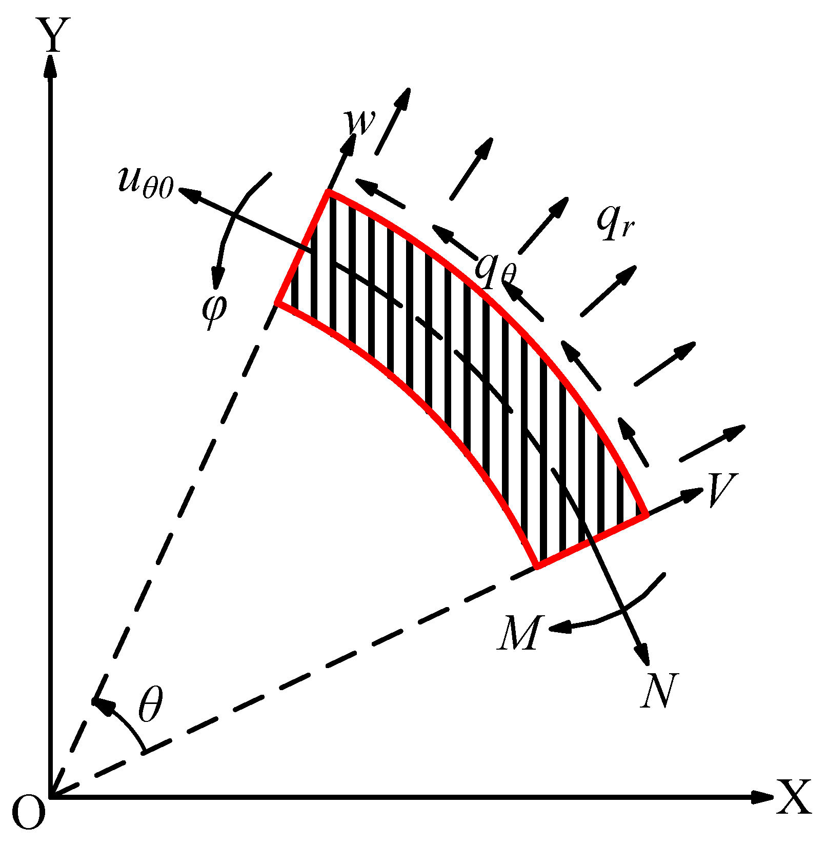
2.1. Curved Timoshenko Beam

Due to the larger diameter of the low-speed gear, and flexible deformation is more likely to be generated, so high-speed gears are still considered rigid bodies, and the ring gear of the low-speed gear is replaced by a flexible smooth ring. The model of uniformly curved Timoshenko beams is shown in Figure 1, and the deformation of the beam can be divided into lateral displacement ( w ), axial displacement ( u θ 0 ) and the rotational displacement of the cross section relative to the section centroid ( φ ), which is calculated by Equation (1) [28]:
{ 5 w θ 5 + 2 3 w θ 3 + w θ = R 2 L ( R 2 E A ) E I E A · q r θ R 2 L G A · 3 q r θ 3 + R 4 L E I · q θ R 2 L ( E A + G A ) G A E A · 2 q θ θ 2 u θ 0 θ = P · ( 4 w θ 4 + 2 w θ 2 ) w + R 2 L E A · q r P R 2 L G A · 2 q r θ 2 P R 2 L ( E A + G A ) G A E A · q θ θ φ = 1 R ( u θ 0 G A + E A G A · w θ ) E A R G A · 2 u θ 0 θ 2 R L G A · q θ P = E I G A R 2 E A G A + E I G A + E I E A
where G and E are the shear modulus and elastic modulus; I and A represent the inertia moment and cross-sectional area of rectangular section of ring gears; θ represents the calculated angular position of the beam; R and L represent the radius and width of flexible ring gears in low-speed gears; and q θ and q r represent axial and radial distributed loads. Assuming zero distributed load, for a uniformly curved Timoshenko beam, the general homogeneous solution for Equation (1) is as follows:
{ w ( θ ) = C 2 C 3 cos θ + C 4 sin θ C 5 ( θ cos θ + P 1 sin θ ) + C 6 ( θ sin θ P 1 cos θ ) u θ 0 ( θ ) = C 1 + C 2 θ + C 3 sin θ + C 4 cos θ + C 5 θ sin θ + C 6 θ cos θ φ ( θ ) = C 1 1 R + C 2 θ R + C 5 P 2 cos θ C 6 P 2 sin θ N ( θ ) = P 3 R ( C 5 sin θ + C 6 cos θ ) V ( θ ) = P 3 R ( C 5 cos θ + C 6 sin θ ) M ( θ ) = C 2 E I R 2 P 3 ( C 5 sin θ + C 6 cos θ )
where C i ( 1 i 6 ) are unknown undetermined coefficients; N ( θ ) , V ( θ ) and M ( θ ) represent the internal force of the beam; and the symbols P i ( 1 i 3 ) can be expressed by the following equation:
{ P 1 = R 2 G A E A + E I E A E I G A R 2 G A E A + E I E A + E I G A P 2 = 2 R G A E A R 2 G A E A + E I E A + E I G A P 3 = 2 E I A E A R 2 G A E A + E I E A + E I G A

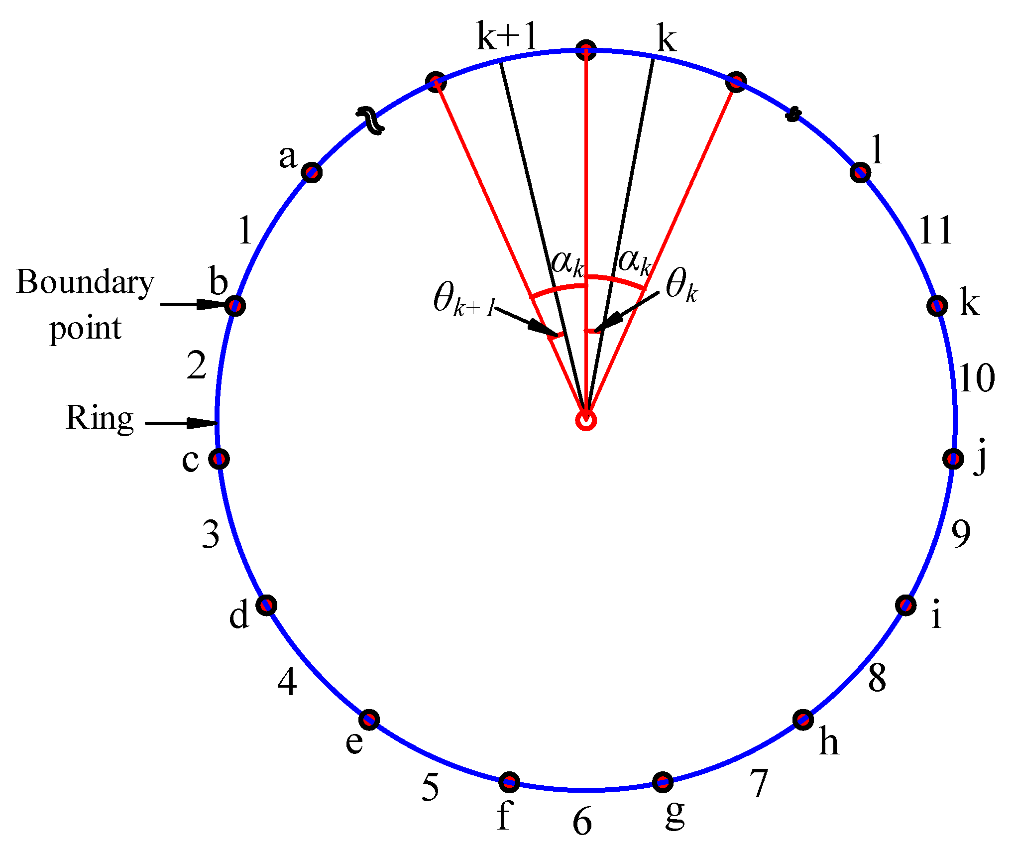
2.2. Discretization of Ring Gears

The ring gear of low-speed gears is divided into m-sections of uniformly curved Timoshenko beams. As shown in Figure 2, the numbers 1, 2, 3… indicate the number of divided curved beams, and the symbols a, b, c… indicate the connection points of two adjacent sections of the beams. θ k / θ k + 1 represents the calculated angular position of two adjacent beams, and α k / α k + 1 represents the corresponding center angle of the two beams. For the boundary conditions imposed at the connection point x of two adjacent beams, two boundary conditions are set according to different forces, as follows:
(1)
When the actual meshing point of gear pairs is close to the k-th section of ring gears, the ring gear of this section is supported by external force, and the boundary conditions are:
{ u θ 0 ( θ k + ) = u θ 0 ( θ k + 1 ) w ( θ k + ) = w ( θ k + 1 ) φ ( θ k + ) = φ ( θ k + 1 ) M ( θ k + 1 ) M ( θ k + ) = m o V ( θ k + 1 ) V ( θ k + ) = F r N ( θ k + 1 ) N ( θ k + ) = F t
(2)
Free support is used in the remaining (m−1) ring gears, and their boundary conditions are:
{ u θ 0 ( θ i + ) = u θ 0 ( θ i + 1 ) w ( θ i + ) = w ( θ i + 1 ) φ ( θ i + ) = φ ( θ i + 1 ) M ( θ i + 1 ) = M ( θ i + ) V ( θ i + 1 ) = V ( θ i + ) N ( θ i + 1 ) = N ( θ i + ) 1 i m , i k
where the symbol ‘+’ indicates the lower boundary of ring gear segments; the symbol ‘−’ indicates the upper boundary of the ring gear segments. The rotation of the low-speed gear ring gear causes the angular position of each ring gear segment to change from time to time. The range of calculated angles θ k of the k-th ring gear segment is [ α 0 + θ g e + 2 k π / m , α 0 + θ g e + 2 ( k + 1 ) π / m ], where, α 0 is the initial phase of the ring gears and θ g e is the rotational angular displacement of low-speed gears.
Figure 3 shows a model of the meshing force and deformation of the ring gear segments. Point A is the actual meshing point; Point O is the center of mass of the ring gear segment where the meshing tooth is located; Point B is the intersection of the action line of the radial force Fb and the center line of the gear tooth; and Fm represents the meshing force of the gear pairs [29].
The deformation δ r i n g of ring gear segments in the direction of LOA and the deformation   δ r i n g perpendicular to LOA are:
{ δ r i n g = w cos θ + u sin θ + φ | OA | sin φ 1         δ r i n g = w sin θ + u cos θ + φ | OA | cos φ 1      
After boundary conditions at each connection point are imposed, six equations can be obtained, and each ring gear segment is described by six unknown, undetermined coefficients, C i k ( 1 i 6 ,   1 k m ) . In this way, after the ring gear is divided into m sections, 6m unknown undetermined coefficients and 6m equations are obtained. Therefore, each unknown undetermined coefficient C i k can be solved. Then undetermined coefficients are put into Equation (2), and the deformation of the ring gear at any time can be obtained.

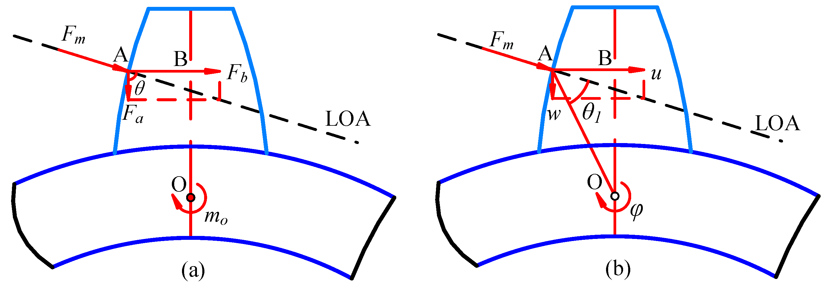
2.3. The Model for TVMS

When there are rectangular spalling faults at the pitch circle of high-speed gears, the model of the spalling fault and the calculated model for the TVMS are as is shown in Figure 4. The length, width and depth of faults are marked as a s ,   b s and h s   , respectively. By using the potential energy method, the TVMS of the gear pairs can be calculated [30,31].
In Figure 4, Ra, Rf and R are the tip circle radius, root circle radius and pitch circle radius, respectively, W and h are the tooth width and total tooth height, a 1 is the actual pressure angle, a 2 represents the half of the center angle corresponding to a gear tooth, h x represents the distance between OP and the meshing point and a x and a s are the pressure angles corresponding to the edge of the spalling fault area. F represents the equivalent concentrated force of the meshing force F M , and F a and F b can be obtained after the meshing force F is decomposed.
Bending deformation energy U b :
U b = 0 d [ F b ( d x ) F a h ] 2 2 E I s d x = F 2 2 k b = R b 1 R 1 1 2 b s [ F cos α 1 ( d x ) F sin α 1 h ] 2 2 E I s d x + R 1 1 2 b s R 1 + 1 2 b s [ F cos α 1 ( d x ) F cos θ sin α 1 h ] 2 2 E I s d x + R 1 + 1 2 b s R a 1 [ F cos α 1 ( d x ) F sin α 1 h ] 2 2 E I s d x
Shear deformation energy U s :
    U s = 0 d ( 1.2 F b ) 2 2 G A x d x = F 2 2 k s = R b 1 R 1 1 2 b s ( 1.2 F cos θ cos α 1 ) 2 2 G A s d x + R 1 1 2 b s R 1 + 1 2 b s ( 1.2 F cos θ cos α 1 ) 2 2 G A s d x + R 1 + 1 2 b s R a 1 ( 1.2 F cos θ cos α 1 ) 2 2 G A s d x  
Radial compression deformation energy U a :
U a = 0 d F a 2 2 E A x d x = F 2 2 k a = R b 1 R 1 1 2 b s ( F cos θ sin α 1 ) 2 2 E A s d x + R 1 1 2 b s R 1 + 1 2 b s ( F cos θ sin α 1 ) 2 2 E A s d x + R 1 + 1 2 b s R a 1 ( F cos θ sin α 1 ) 2 2 E A s d x
A x ,     I x are the cross-sectional area and inertia moment of the tooth, which is determined by the following equations:
{ A s = 2 h x W Healthy A s = 2 h x W a s h s Spalling
{ I s = ( 2 h x W ) 3 12 Healthy I s = ( 2 h x W ) 3 h s 3 a s 12 Spalling
Then, the stiffness components are obtained.
Bending stiffness k b :
1 k b = α 1 α x 3 cos α ( α 2 α ) { 1 cos α 1 [ cos α ( α 2 α ) sin α ] } 2 2 E W [ ( α 2 α ) cos α + sin α ] 3 d α + α x α s 12 cos α ( α 2 α ) { 1 cos α 1 [ cos α ( α 2 α ) sin α ] } 2 E { 8 W [ ( α 2 α ) cos α + sin α ] 3 ( h s / R b 1 ) 3 a s } d α + α s α 2 3 cos α ( α 2 α ) { 1 cos α 1 [ cos α ( α 2 α ) sin α ] } 2 2 E W [ ( α 2 α ) cos α + sin α ] 3 d α
Shear stiffness k s :
1 k s = α 1 α x 1.2 ( 1 + v ) ( α 2 α ) cos α cos 2 α 1 cos 2 θ E W [ ( α 2 α ) cos α + sin α ] d α + α x α s 2.4 ( 1 + v ) ( α 2 α ) cos α cos 2 α 1 cos 2 θ E { 2 W [ ( α 2 α ) cos α + sin α ] ( h s / R b 1 ) a s } d α + α s α 2 1.2 ( 1 + v ) ( α 2 α ) cos 2 α 1 cos 2 θ cos α E W [ ( α 2 α ) cos α + sin α ] d α
Radial compression stiffness k a :
1   k a = α 1 α x ( α 2 α ) cos α sin 2 α 1 cos 2 θ 2 E W [ ( α 2 α ) cos α + sin α ] d α + α x α s ( α 2 α ) cos α sin 2 α 1 cos 2 θ E { 2 W [ ( α 2 α ) cos α + sin α ] ( h s / R b 1 ) a s } d α + α s α 2 ( α 2 α ) cos α sin 2 α 1 cos 2 θ 2 E W [ sin α + ( α 2 α ) cos α ] d α
The stiffness k ring caused by the deformation of the ring gears is introduced, so the TVMS of the gear pairs is calculated as:
1 k t = { 1 k h + 1 k b 1 + 1 k s 1 + 1 k a 1 + 1 k b 2 + 1 k s 2 + 1 k a 2 + 1 k ring Single tooth i = 1 2 ( 1 k h , i + 1 k a 1 , i + 1 k b 1 , i + 1 k s 1 , i + 1 k b 2 , i + 1 k s 2 , i + 1 k ring + 1 k a 2 , i ) Double teeth
where k ring = F m / δ r i n g . Yang’s model [32] is imitated to complete the calculation of Hertzian stiffness, k h .

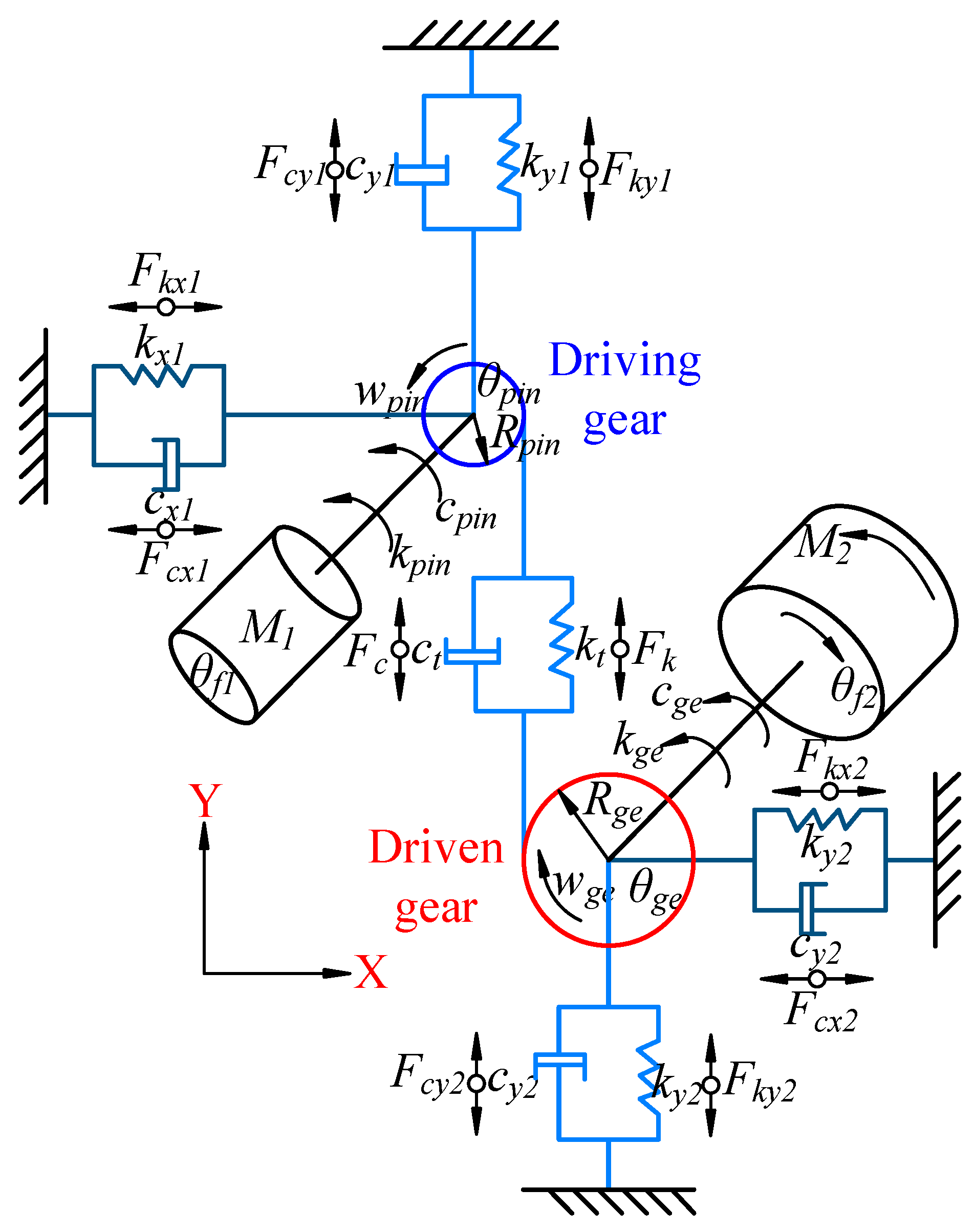
2.4. System Equations of the Gear Pairs

As shown in Figure 5, the Lagrangian equation is used to establish the eight-DOFs vibration equations for the spur gear pairs. The dynamic model equations are as follows [33,34].
The motion equation of the input shaft is:
I f 1 θ ¨ f 1 + c p i n ( θ ˙ f 1 θ ˙ p i n ) + k p i n ( θ f 1 θ p i n ) = M 1
where θ f 1 and θ p i n are the angular displacement of the input shaft and driving gear; I f 1 indicates the inertia moment of the high-speed shaft; and M 1 is the input torque. c p i n and k p i n indicate the torsional damping and torsional stiffness of the high-speed shaft.
The motion equation of the output shaft is:
I f 2 θ ¨ f 2 + c g e ( θ ˙ f 2 θ ˙ g e ) + k g e ( θ f 2 θ g e ) = M 2
where I f 2 indicates the inertia moment of the low-speed shaft; θ f 2 and θ g e represent the output shaft angular displacement and driven gear angular displacement;   M 2 indicates the load torque of the transmission system; and c g e and k g e are the torsional damping and torsional stiffness.
The motion equations of the driving gear are:
{ I p i n θ ¨ p i n c p i n ( θ ˙ p i n θ ˙ f 1 ) k p i n ( θ p i n θ f 1 ) = R b 1 F M m p i n x ¨ p i n + c x 1 x ˙ p i n + k x 1 x p i n = 0 m p i n y ¨ p i n + c y 1 y ˙ p i n + k y 1 y p i n = F M
where m p i n indicates the mass of driving gear; R b 1 represents the base circle radius; I p i n represents the inertia moment; x p i n and y p i n indicate the linear displacement of the high-speed gear; and k x 1 ,   k y 1 ,   c x 1 and c y 1 are the support stiffness and damping.
The motion equations of the driven gear are:
{ I g e y ¨ g e c g e ( θ ˙ g e θ ˙ f 2 ) k g e ( θ g e θ f 2 ) = R b 2 F M m r i n g δ ¨ r i n g + c x 2 ( δ ˙ r i n g x ˙ g e ) + k x 2 ( δ r i n g y g e ) = 0 m r i n g δ ¨ r i n g + c y 2 ( δ ˙ r i n g y ˙ g e ) + k y 2 ( δ r i n g y g e ) = F M
where m r i n g is the mass of ring gears; I g e represents the inertia moment of driven gear; R b 2 represents the base circle radius; and k x 2 ,   k y 2 ,   c x 2 and c y 2 represent the support stiffness and damping.
The nonlinearity of meshing force F M of the gear pairs is considered, which is mainly divided into the viscous force F c and elastic force F k , as follows:
{ F M = F k + F c F k = k t ( R b 1 θ p i n R b 2 θ g e y p i n + y g e e t ) F c = c t ( R b 1 θ ˙ p i n R b 2 θ ˙ g e y ˙ p i n + y ˙ g e e t ˙ )  
where e t ˜ represents the transmission error and is simulated by trigonometric function [35].
e t = e o + e m sin ( 2 π f m t + φ o )
where e m and e o represent the fluctuation and average error.

2.5. Model Solving

The main parameter for the gear pairs is selected as shown in Table 1, and parameters for system equations are listed in Table 2. The Runge–Kutta method is used to solve the system equations. The total working time and working step are set to 2 s and 10 5 s and the initial state of the system is set to 0.

3. Result Analysis

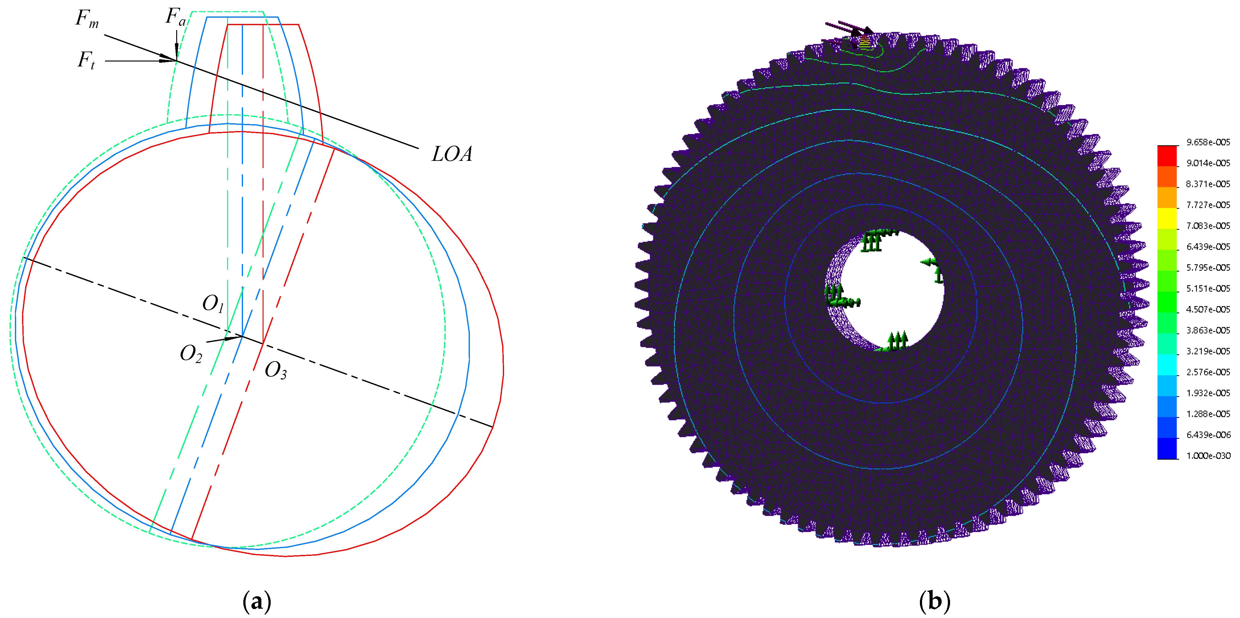
3.1. Deformation of Ring Gears

The deformation of ring gears after the system equations are solved is shown in Figure 6. It is seen that the ring gear is deformed during transmission, and the deformed shape is changed from a circle to an ellipse. The long axis of the deformed elliptical gear ring is parallel to the LOA, the short axis is perpendicular to the LOA and the center of the gear rings is moved along the LOA due to the meshing force and the supporting force.
The green dashed line in Figure 6a represents a rigid ring gear, and it is not deformed and presents a round shape. The blue solid line represents the deformed shape of the flexible ring gears when the double teeth of the gear pair are meshed. Due to the load per unit length of the gear teeth being smaller, the force arm is relatively large and the ring gear suffers more bending moments so that the deformation of the ring gears near the meshing point is mainly manifested as bending deformation. The red solid line indicates the deformation of the flexible ring gears in the single-tooth meshing interval, and the meshing force between the teeth and the force per unit length of the gear teeth are relatively large so the main form of meshing force acting on the flexible gear ring is pressure, which causes the main form of deformation of the gear ring to be stretched under tension. At this time, the deformation of the flexible gear ring is relatively large.
The FEM results for the flexible gear rings are shown in Figure 6b. According to the deformation at different ring gear radius positions, in addition to the complicated deformation of the ring gear near the actual meshing point, the overall shape of the ring gear after deformation presents an elliptical shape. Moreover, the angular error between the long axis of the ellipse and the line of action (LOA) of the meshing force is relatively small.
The results of the FEM are similar to the results obtained by establishing the mathematical model. It can be considered that the established model is in good agreement with the actual deformation of the ring gears. The flexible ring gear deforms after being subjected to the meshing force, and the deformed shape is roughly elliptical.

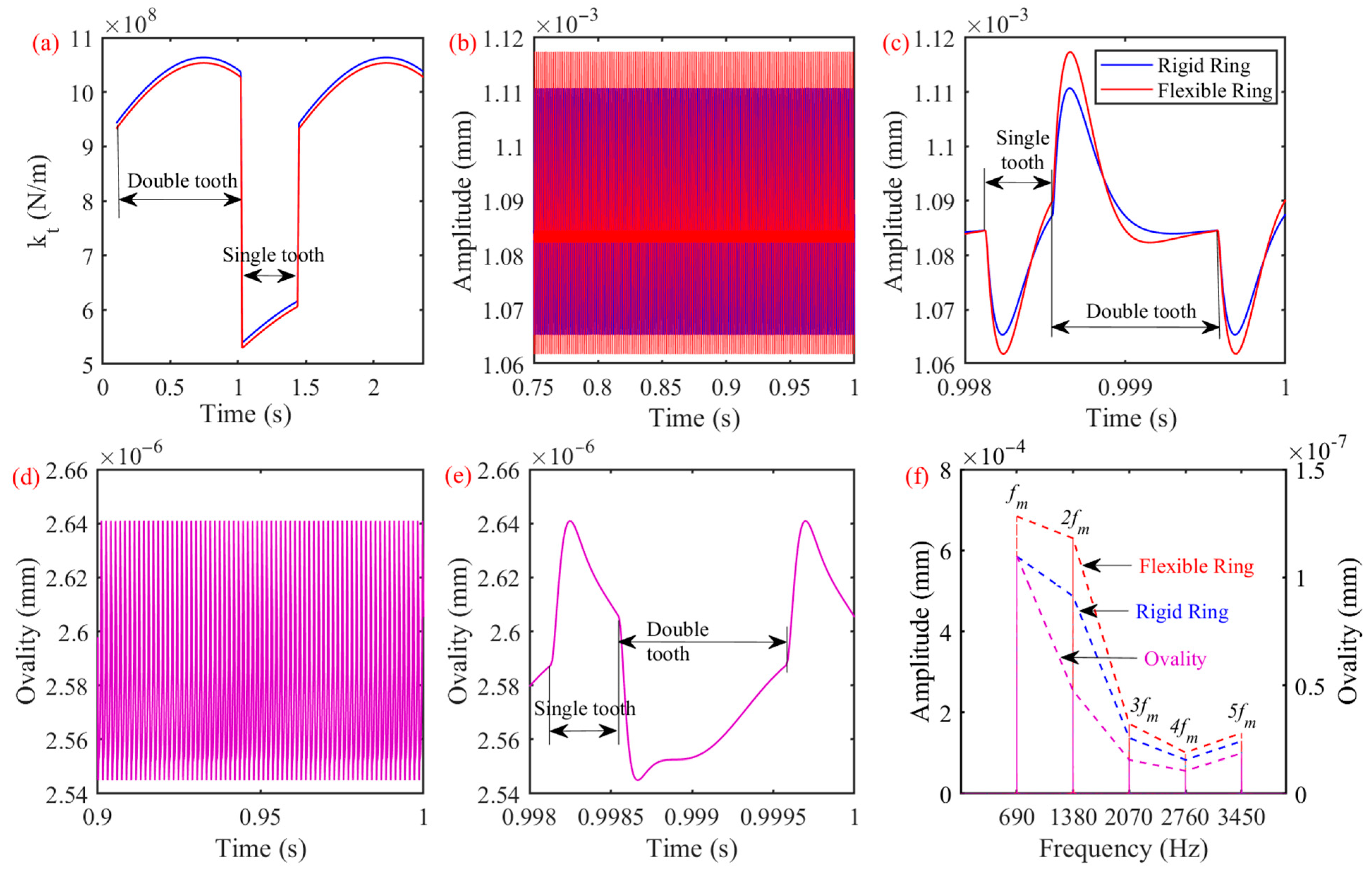
3.2. Dynamic Response of the Gear Pairs

The dynamic excitation and vibration of the healthy gear pairs is given in Figure 7, and the TVMS is provided in Figure 7a. During the meshing process, the TVMS of the gear pair with flexible ring gears also changes periodically, and after the flexibility of the ring gears is considered, the TVMS is reduced slightly. The dynamic displacement of the ring gears in the y direction is shown in Figure 7b, and it is found that the response of the healthy rigid gear pairs and healthy gear pairs with a flexible ring gear are both stable, without obvious shock. However, due to the stiffness caused by the flexible deformation of the ring gears, the TVMS of the gear pairs is reduced, which causes an increase in the displacement amplitude of the gear pair with flexible ring gears. A period of the time-domain response in Figure 7b is extracted and plotted, as shown in Figure 7c. There are sudden changes at the beginning of the single- and double-tooth meshing intervals. In addition, due to the flexible deformation, the response amplitude of the gear pair with flexible ring gears is greater than the rigid gear ring.
The above result demonstrates that the deformed ring gear presents an elliptical shape. For quantifying the deformation of the flexible ring gears, the ovality can be used to describe the deformation degree of the ring gears. The ovality of the flexible ring gears is shown in Figure 7d, and it is found that the ovality also exhibits time-varying characteristics and changes periodically. One period of the ovality curve is extracted and provided in Figure 7e. It can be found that the ovality of the flexible ring gears is closely related to the meshing of the single and double teeth, and the ovality curve is continuous and uninterrupted. In the single-tooth meshing interval of the gear pairs, the ovality shows a continuous decreasing trend, and at the beginning of the single-tooth meshing interval, the ovality value is the largest, which means that the deformation of the flexible ring gear is the largest. When the gear pair is driven by two pairs of gear teeth, the ovality of the flexible ring gears shows a tendency of increasing, but its ovality value is smaller than that in the single-tooth meshing interval as a whole.
After the time-domain response in Figure 7b and the ovality curve in Figure 7d are converted by the fast Fourier transform (FFT), the spectrum of Figure 7f can be obtained. It can be seen that whether it is a rigid gear pair or a flexible gear pair, the components of spectrum are mainly composed of the meshing frequencies f m , 2 f m , 3 f m , 4 f m . However, the increase in amplitudes of the gear pairs with flexible ring gears is caused by the decrease of the TVMS. In addition, it can be seen that there are only meshing frequencies f m , 2 f m , 3 f m , 4 f m on the ovality spectrum, which can explain that the main excitation of the ring gear’s flexible deformation is the meshing behavior of the gear pairs.

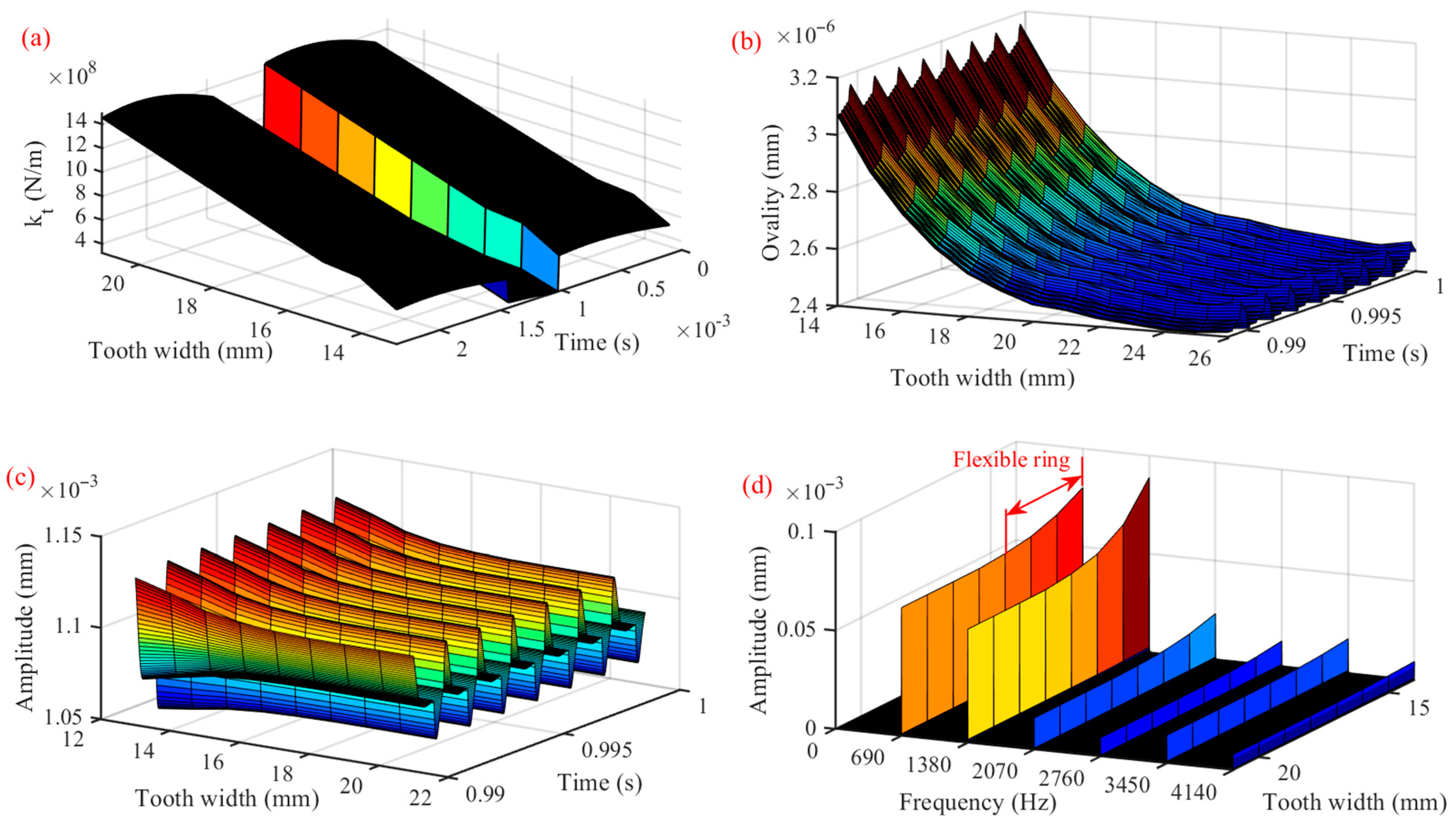
3.3. Dynamic Response of Gear Pairs with Different Flexible Gear Rim Widths

The width of the flexible ring gear rims has a significant effect on the vibration response of the gear pairs. Next, by setting different gear rim widths, while the width of the gear teeth remains unchanged, the vibration characteristics of gear pairs are studied. The dynamic model of the gear pair under different gear rim widths is explored, and the results are displayed in Figure 8.
The TVMS of gear pairs with different ring gear widths is shown in Figure 8a. As the width of flexible ring gears increases, the TVMS shows an increasing trend due to the reduction of ring gear deformation. The ovality curve under different flexible gear rim widths is provided in Figure 8b. As the rim width increases, the ovality value continues to decrease, which indicates that the ring gears are not prone to deformation, and increasing the rim width can effectively suppress the deformation of the ring gears. Additionally, when the rim width is small, the ovality value drops quickly. As the width continues to increase, the ovality value decreases gently. This can indicate that when the rim thickness is small, the thin-walled ring gear exhibits strong flexible deformation characteristics. When the thickness of the ring gears is large, the deformation is almost no longer reduced so that the gear pair tends to exhibit rigid characteristics.
Figure 8c explains the vibration in the y direction of the driven gear ring with different rim widths. It can be found that when the width of the rim increases, the vibration amplitude is decreased due to the reduction of ring gear deformation and the increase of the TVMS. After the time-domain response of Figure 8c is transformed by the FFT, the spectrum of Figure 8d is acquired. The main component of the spectrum is still the meshing frequency f m , 2 f m , 3 f m , 4 f m of the gear pair, and when the rim width is increased, the amplitude of meshing frequencies shows a decreasing trend. Particularly, when the width of the rim is small, the deformation of the thin-walled flexible ring gears is large, which results in the amplitude of the double frequency 2 f m being greater than the fundamental frequency f m of the meshing frequency. When the rim width is small, the thin-walled ring gear exhibits strong flexible deformation, which increases the actual center distance of the gear pairs. Therefore, there are vibration characteristics of the center distance error of the gear pairs in the spectrum.

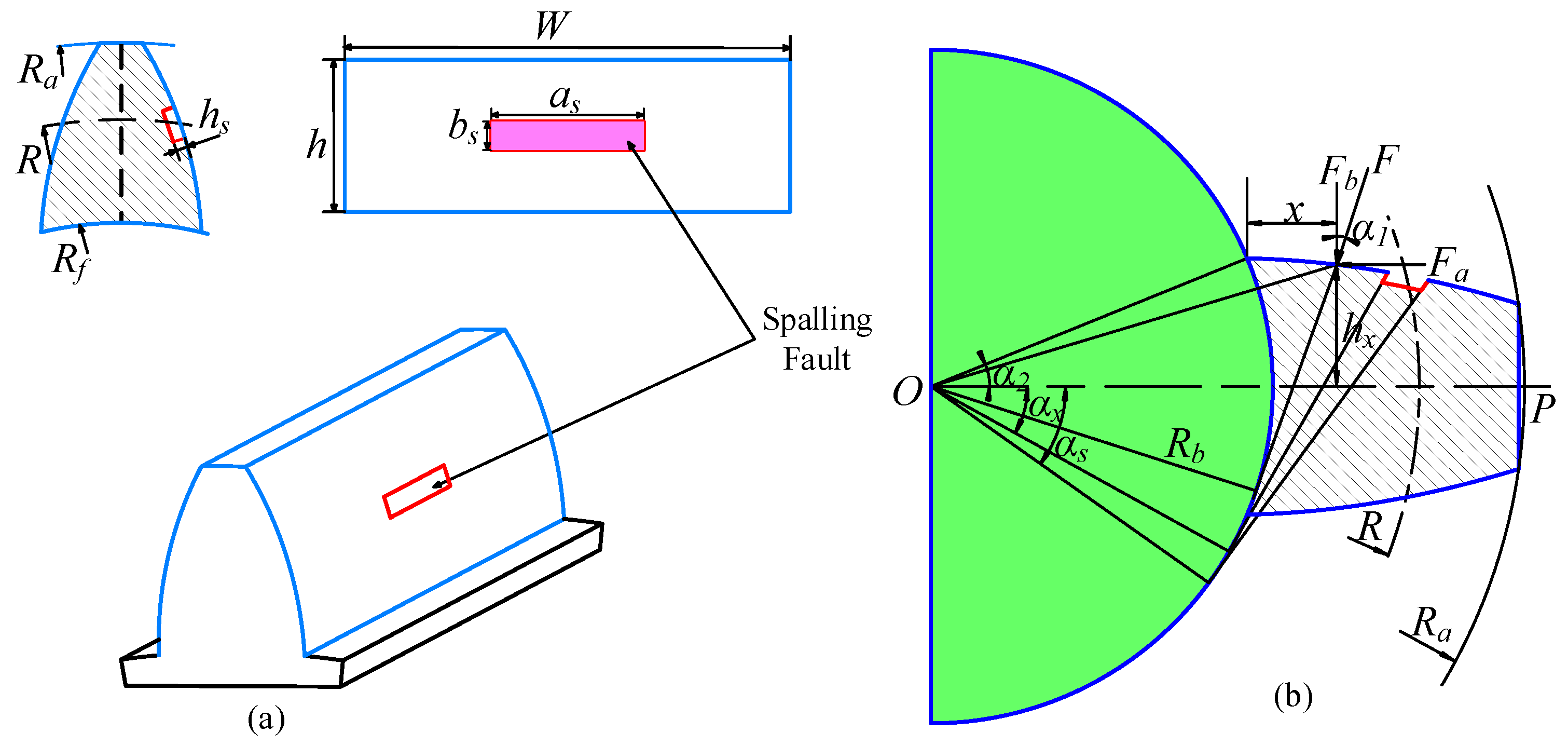
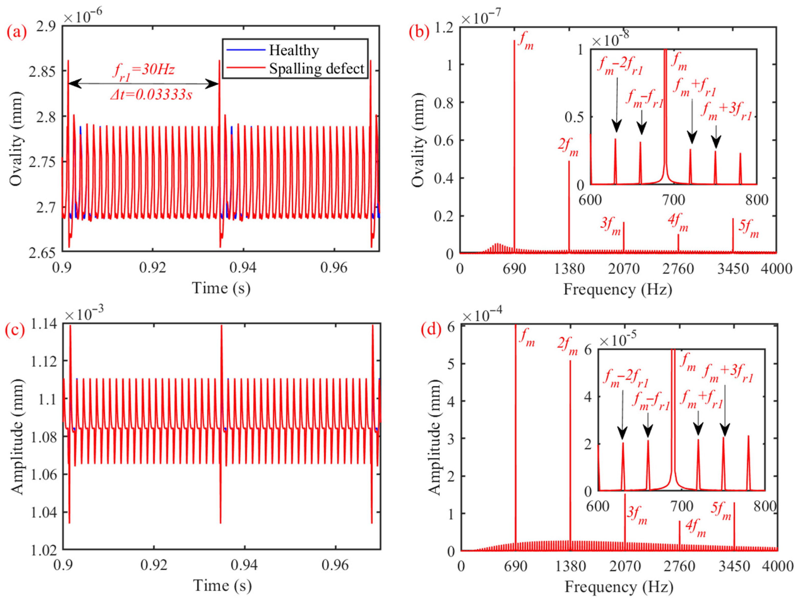
3.4. Response of Gear Pairs with a Localized Spalling Fault
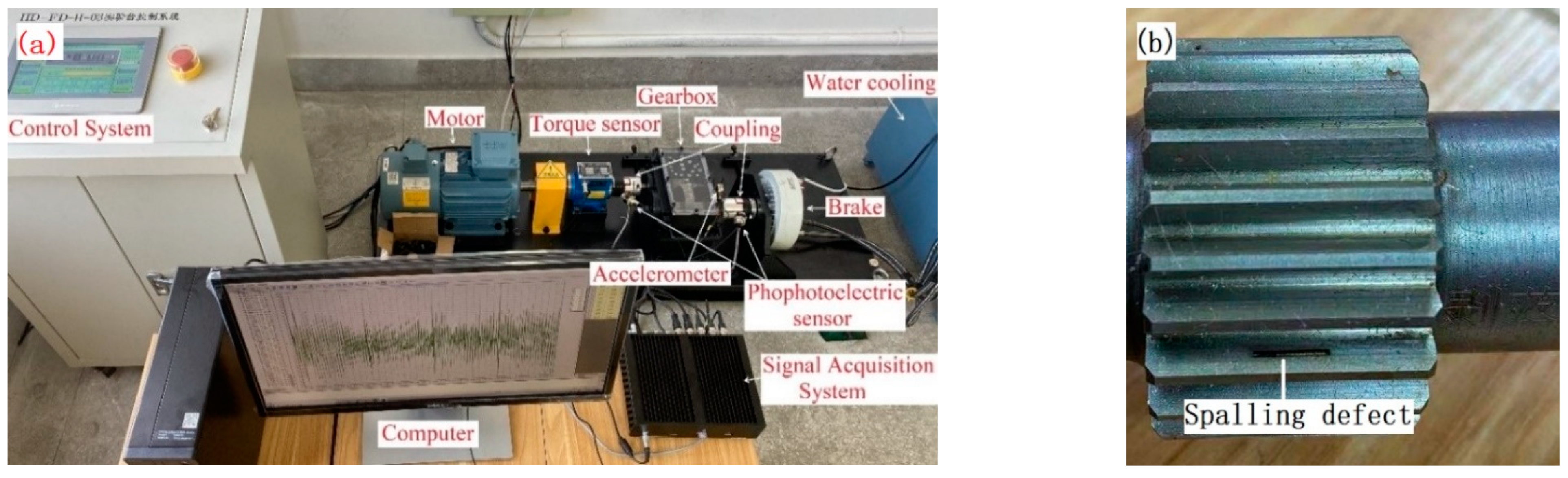
When there are spalling faults on gear pairs, in order to highlight the excitation of the fault on the deformation of the ring gear, the length a s , width b s and depth h s of the spalling defects are set to 6 mm, 2 mm and 0.2 mm, respectively. After the system equations of the gear pairs are solved, the obtained dynamic displacement is given in Figure 9.
The ovality of the flexible gear rings is shown in Figure 9a. When there are local faults on high-speed gears, the meshing force is impacted, and the sudden change in the flexible deformation of the ring gears is caused, and there is shock on the ovality curve. The time interval between adjacent shocks is 0.0333 s, which corresponds to the input frequency f r 1 =   30 Hz of the driving gears. As shown in Figure 9b, the ovality curve in Figure 9a is converted by the FFT, and then the spectrum of the ovality can be obtained. In addition to the meshing frequency f m , 2 f m , 3 f m , 4 f m , there are also harmonic frequencies generated by modulation, such as f m ± f r 1 ,   f m ± 2 f r 1 . The time-domain response and frequency-domain response of the gear pairs are shown in Figure 9c,d. Similarly, when there are localized spalling faults on the high-speed gears, there is periodic shock on the time-domain response of the ring gears in the y direction, and its spectrum composition is similar to that of the ovality.

4. Experiment

4.1. Experimental Equipment

The gearbox test bench in Figure 10a is used for obtaining the response of the gear pairs. The high-speed gear with localized spalling faults is given in Figure 10b. The fault length is 6 mm, the width is 2 mm and the depth is 0.2 mm. The braking torque is 10 N·m, and the input speed is controlled at 1800 rpm. The tooth width of the gear pairs is 25 mm, and other components used in experiments are consistent with those set by the system equations.
The dynamic response of the gearbox is collected by the acquisition system, and the acceleration response of the plumb direction is measured, and the acquisition frequency is 30 k Hz. The corresponding measuring point is the bearing end cap. Then, the obtained signal is denoised by low-pass filtering.

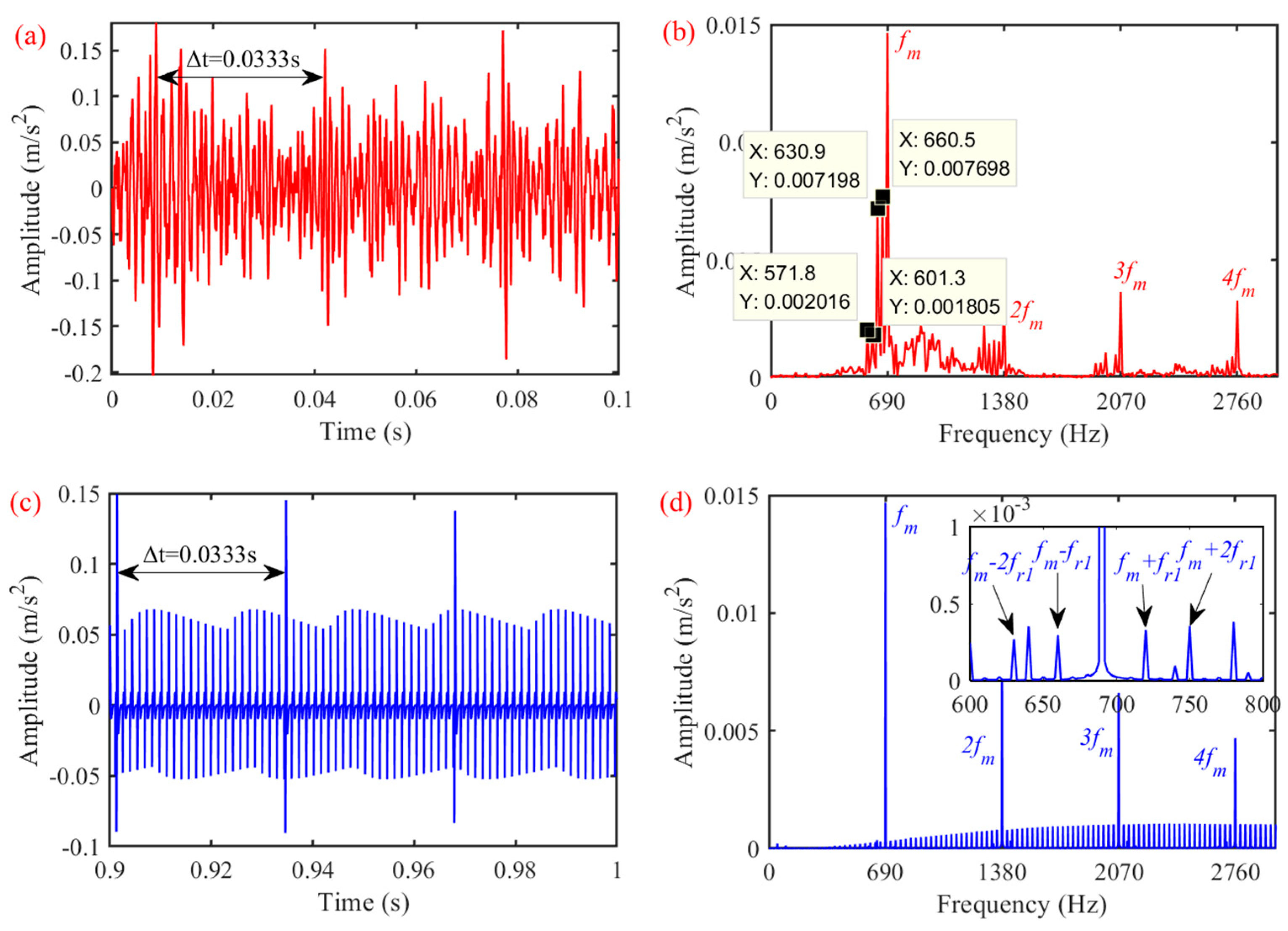
4.2. Experimental Results

For comparing the response signal collected by experiments with the vibration response obtained from the mathematical model, the system equations are solved, and then the acceleration of the ring gears in the high-speed gear in the y direction is extracted. After the test, the response of the gear pairs with faults is shown in Figure 11.
The measured acceleration response is shown in Figure 11a. It is found that due to the localized defect, periodic shocks are generated in the response signal. The average distance between adjacent shock peaks is 0.0333 s, which corresponds to the rotation frequency of the high-speed gear. The spectrum is shown in Figure 11b, which is primarily composed of meshing frequencies f m , 2 f m , 3 f m , 4 f m of the gear pairs. Due to the localized fault, harmonic frequencies are generated, such as f m ± f r 1 ,   f m ± 2 f r 1 , and the frequency interval is 30 Hz.
The acceleration response of the gear pairs obtained from the mathematical model is provided in Figure 11c,d. The result is similar to the experimentally measured signal, which verifies the mathematical model established in this paper.

5. Conclusions

In order to study the deformation of flexible ring gears and vibration response of spur gear pairs, a mathematical model of gear pairs is proposed. By using the model, the deformation of flexible gear rings and vibration response of the gear pair is studied. Then, the effects of flexible ring gear rim widths and localized faults on the deformation of the ring gears and the dynamic response of the gear pairs are further discussed. The main results summarized are as follows:
(1)
The flexible ring gear is deformed due to the meshing force, and the deformed shape is close to an ellipse. In single-tooth meshing intervals, the main form of deformation is being stretched, and in double-tooth meshing intervals, the main form is bending.
(2)
After the ovality is used to describe the deformation degree of the ring gear, it is found that in single-tooth meshing interval, the ovality value keeps decreasing. When the gear pair is meshed with two pairs of teeth, the ovality value shows an increasing trend.
(3)
The flexible deformation of the ring gear can be effectively suppressed by increasing the rim width.
(4)
When there are localized spalling faults on gear pairs, the deformation of flexible ring gears is also abruptly changed due to the shock of the meshing force.

Author Contributions

Conceptualization, S.Y.; methodology, P.D.; software, S.Y.; validation, D.S.; formal analysis, S.W. and P.D.; investigation, D.S. and J.W.; data curation, P.L.; resources, S.W.; writing—review and editing, P.D.; writing—original draft preparation, D.Z. and S.Y.; visualization, H.L.; supervision, D.S. and H.L.; project administration, D.Z. All authors have read and agreed to the published version of the manuscript.

Funding

The work is funded by the Guizhou Provincial Science and Technology Projects (No. GCC[2022]007-1), the Collaborative Innovation Fund project of Anhui Polytechnic University and Jiujiang District (No. 2022cyxtb3), the Natural Science Foundation of Anhui Province (No. 2108085ME165).

Institutional Review Board Statement

Not applicable.

Informed Consent Statement

Not applicable.

Data Availability Statement

Not applicable.

Conflicts of Interest

The authors declare no conflict of interest.

References

  1. Li, W.; Sun, J.; Yu, J. Analysis of dynamic characteristics of a multi-stage gear transmission system. J. Vib. Control 2019, 25, 1653–1662. [Google Scholar] [CrossRef]
  2. Palermo, A.; Mundo, D.; Hadjit, R.; Desmet, W. Multibody element for spur and helical gear meshing based on detailed three-dimensional contact calculations. Mech. Mach. Theory 2013, 62, 13–30. [Google Scholar] [CrossRef]
  3. Ligata, H.; Kahraman, A.; Singh, A. A Closed-Form Planet Load Sharing Formulation for Planetary Gear Sets Using a Translational Analogy. J. Mech. Des. 2009, 131, 021007. [Google Scholar] [CrossRef]
  4. Guo, Y.; Parker, R.G. Analytical determination of back-side contact gear mesh stiffness. Mech. Mach. Theory 2014, 78, 263–271. [Google Scholar] [CrossRef]
  5. Zhang, B.; Liu, H.; Zhu, C.; Li, Z. Numerical simulation of competing mechanism between pitting and micro-pitting of a wind turbine gear considering surface roughness. Eng. Fail. Anal. 2019, 104, 1–12. [Google Scholar] [CrossRef]
  6. Huang, K.J.; Su, H.W. Approaches to parametric element constructions and dynamic analyses of spur/helical gears including modifications and undercutting. Finite Elem. Anal. Des. 2010, 46, 1106–1113. [Google Scholar] [CrossRef]
  7. Barbieri, M.; Zippo, A.; Pellicano, F. Adaptive grid-size finite element modeling of helical gear pairs. Mech. Mach. Theory 2014, 82, 17–32. [Google Scholar] [CrossRef]
  8. Liu, J.; Yuan, L. Vibration analysis of a flexible gearbox system considering a local fault in the outer ring of the supported ball bearing. J. Vib. Control 2001, 27, 1063–1076. [Google Scholar] [CrossRef]
  9. Omar, F.K.; Moustafa, K.A.; Emam, S. Mathematical modeling of gearbox including defects with experimental verification. J. Vib. Control 2021, 18, 1310–1321. [Google Scholar] [CrossRef]
  10. Jiang, H.; Shao, Y.; Mechefske, C.K. Dynamic characteristics of helical gears under sliding friction with spalling defect. Eng. Fail. Anal. 2014, 39, 92–107. [Google Scholar] [CrossRef]
  11. Ma, H.; Pang, X.; Zeng, J.; Wang, Q.; Wen, B. Effects of gear crack propagation paths on vibration responses of the perforated gear system. Mech. Syst. Signal Process. 2015, 62–63, 113–128. [Google Scholar] [CrossRef]
  12. Lewicki, D.G.; Ballarini, R. Effect of Rim Thickness on Gear Crack Propagation Path. J. Mech. Des. 1997, 119, 88–95. [Google Scholar] [CrossRef] [Green Version]
  13. Jia, S.; Howard, I. Comparison of localised spalling and crack damage from dynamic modeling of spur gear vibrations. Mech. Syst. Signal Process. 2006, 20, 332–349. [Google Scholar] [CrossRef]
  14. Howard, I.; Jia, S.; Wang, J. The dynamic modelling of a spur gear in mesh including friction and a crack. Mech. Syst. Signal Process. 2001, 15, 831–853. [Google Scholar] [CrossRef]
  15. Ma, R.; Chen, Y. Research on the dynamic mechanism of the gear system with local crack and spalling failure. Eng. Fail. Anal. 2012, 26, 12–20. [Google Scholar] [CrossRef]
  16. Chen, Z.; Shao, Y. Dynamic simulation of spur gear with tooth root crack propagating along tooth width and crack depth. Mech. Mach. Theory 2011, 18, 2149–2164. [Google Scholar] [CrossRef]
  17. Liang, X.; Zhang, H.; Liu, L.; Zuo, M.J. The influence of tooth pitting on the mesh stiffness of a pair of external spur gears. Mech. Mach. Theory 2016, 106, 1–15. [Google Scholar] [CrossRef]
  18. Chen, Z.; Shao, Y. Mesh stiffness calculation of a spur gear pair with tooth profile modification and tooth root crack. Mech. Mach. Theory 2013, 62, 63–74. [Google Scholar] [CrossRef]
  19. Chen, Z.; Shao, Y. Dynamic features of planetary gear train with tooth errors. Proc. Inst. Mech. Eng. Part C J. Mech. Eng. Sci. 2015, 229, 1769–1781. [Google Scholar] [CrossRef]
  20. Ma, H.; Zeng, J.; Feng, R.; Pang, X.; Wen, B. An improved analytical method for mesh stiffness calculation of spur gears with tip relief. Mech. Mach. Theory 2016, 98, 64–80. [Google Scholar] [CrossRef]
  21. Wu, S.; Cheng, H.S. Sliding Wear Calculation in Spur Gears. J. Tribol. 1993, 115, 493–500. [Google Scholar] [CrossRef]
  22. Sainsot, P.; Velex, P.; Duverger, O. Contribution of Gear Body to Tooth Deflections-A New Bidimensional Analytical Formula. J. Mech. Des. 2004, 126, 748–752. [Google Scholar] [CrossRef]
  23. Kahraman, A.; Vijayakar, S. Effect of Internal Gear Flexibility on the Quasi-Static Behavior of a Planetary Gear Set. J. Mech. Des. 2001, 123, 409–415. [Google Scholar] [CrossRef]
  24. Abousleiman, V.; Velex, P. A hybrid 3D finite element/lumped parameter model for quasi-static and dynamic analyses of planetary/epicyclic gear sets. Mech. Mach. Theory 2006, 41, 725–748. [Google Scholar] [CrossRef]
  25. Parker, R.G.; Wu, X. Vibration modes of planetary gears with unequally spaced planets and an elastic ring gear. J. Sound Vib. 2010, 329, 2265–2275. [Google Scholar] [CrossRef]
  26. Wu, X.; Parker, R.G. Vibration of rings on a general elastic foundation. J. Sound Vib. 2006, 295, 194–213. [Google Scholar] [CrossRef]
  27. Chen, Z.; Shao, Y. Mesh stiffness of an internal spur gear pair with ring gear rim deformation. Mech. Mach. Theory 2013, 69, 1–12. [Google Scholar] [CrossRef]
  28. Gasmi, A.; Joseph, P.F.; Rhyne, T.B.; Cron, S.M. Closed-form solution of a shear deformable, extensional ring in contact between two rigid surfaces. Int. J. Solids Struct. 2011, 48, 843–853. [Google Scholar] [CrossRef] [Green Version]
  29. Ruiz Barrios, M.L.; Hernández Montero, F.E.; Gómez Mancilla, J.C.; Palomino Marín, E. Tacho-less automatic rotational speed estimation (TARSE) for a mechanical system with gear pair under non-stationary conditions. Measurement 2019, 145, 480–494. [Google Scholar] [CrossRef]
  30. Li, Z.; Zhu, C.; Liu, H.; Gu, Z. Mesh stiffness and nonlinear dynamic response of a spur gear pair considering tribo-dynamic effect. Mech. Mach. Theory 2020, 153, 103989. [Google Scholar] [CrossRef]
  31. Saxena, A.; Parey, A.; Chouksey, M. Effect of shaft misalignment and friction force on time varying mesh stiffness of spur gear pair. Eng. Fail. Anal. 2015, 49, 79–91. [Google Scholar] [CrossRef]
  32. Yang, D.C.H.; Lin, J.Y. Hertzian Damping, Tooth Friction and Bending Elasticity in Gear Impact Dynamics. J. Mech. Des. 1987, 109, 189–196. [Google Scholar] [CrossRef]
  33. Chaari, F.; Baccar, W.; Abbes, M.S.; Haddar, M. Effect of spalling or tooth breakage on gearmesh stiffness and dynamic response of a one-stage spur gear transmission. Eur. J. Mech.-A/Solids 2008, 27, 691–705. [Google Scholar] [CrossRef]
  34. Park, S.; Kim, S.; Choi, J.-H. Gear fault diagnosis using transmission error and ensemble empirical mode decomposition. Mech. Syst. Signal Process. 2018, 108, 262–275. [Google Scholar] [CrossRef]
  35. Jun, Z.; Wei-min, T.; Qin, C.; Tao, C. Reliability sensitivity analysis of tooth modification on dynamic transmission error of helical planetary gears. Proc. Inst. Mech. Eng. Part C J. Mech. Eng. Sci. 2020, 234, 3903–3918. [Google Scholar] [CrossRef]
Figure 1. Uniformly curved Timoshenko beam model.
Machines 10 00560 g001
Figure 2. Discretization of the ring gear.
Machines 10 00560 g002
Figure 3. Force and displacement at the meshing point: (a) decomposition of Fm; (b) displacement of meshing point.
Machines 10 00560 g003
Figure 4. Model of spalling faults: (a) fault on high-speed gear; (b) model for the TVMS.
Machines 10 00560 g004
Figure 5. The vibration model of gear pairs.
Machines 10 00560 g005
Figure 6. Deformation of gear rings: (a) model solution results; (b) FEM results.
Machines 10 00560 g006
Figure 7. Dynamic response of healthy gear pairs: (a) meshing stiffness; (b) time-domain response of the gear pair; (c) one period of time-domain response; (d) ovality of ring gears after deformation; (e) one period of the ovality curve; (f) frequency-domain response.
Machines 10 00560 g007
Figure 8. Dynamic response of gear pairs with different flexible gear rim widths: (a) meshing stiffness; (b) ovality of the ring gear after deformation; (c) response of gear pairs; (d) frequency-domain response.
Machines 10 00560 g008
Figure 9. Response of gear pairs with spalling faults: (a) ovality curve time domain; (b) ovality curve frequency domain; (c) time-domain response of gear pairs; (d) frequency-domain response.
Machines 10 00560 g009
Figure 10. Experimental equipment: (a) experimental bench; (b) gear with localized defects.
Machines 10 00560 g010
Figure 11. Response of gear pair with a localized fault; (a) time-domain signal measured by experiment; (b) frequency-domain signal measured by experiment; (c) response obtained by simulation; (d) spectrum obtained by simulation.
Machines 10 00560 g011
Table 1. Parameters of gear pairs.
ParameterDriving GearDriven Gear
Gear modulus m/mm22
Teeth number z2381
Pressure Angle α/(°)2020
Gear width W/mm2525
Elastic modulus E/GPa208208
Poisson ratio v0.310.31
Table 2. Parameters of system equations.
ParameterValues
Mass   of   driving   gear   m p i n / kg 0.96
Mass   of   driven   gear   m g e / k g 2.88
Inertia   moment   of   driving   gear   I p i n / ( kg m 2 ) 4.365 × 10⁻⁴
Inertia   moment   of   driven   gear   I g e / ( kg m 2 ) 8.362 × 10⁻⁴
Inertia   moment   of   input   shaft   I f 1 / ( kg m 2 ) 0.0021
Inertia   moment   of   output   shaft   I f 2 / ( kg m 2 ) 0.0105
Torsional   stiffness   of   shaft   k x 1 , k x 2 , k y 1 , k y 2 / ( N / m ) 4.4 × 10 4
Torsional   damping   of   shaft   c x 1 , c x 2 , c y 1 , c y 2 / ( Nms / rad ) 5.0 × 10 5
Transmission   fluctuation   range   e m / m 3 × 10⁻⁵
Mean   transmission   error   e o / m 2 × 10⁻⁵
High - speed   shaft   rotation   frequency   f r 1 / Hz 30
Meshing   frequency   of   gear   pairs   f m / Hz 690
Load   T 2 / ( N · m ) 10
Publisher’s Note: MDPI stays neutral with regard to jurisdictional claims in published maps and institutional affiliations.

