
Velocity and Singularity Analysis of a 5-DOF (3T2R) Parallel-Serial (Hybrid) Manipulator


1
Department of Fundamentals of Machine Design, Bauman Moscow State Technical University (BMSTU), Moscow 105005, Russia
2
Mechanisms Theory and Machines Structure Laboratory, Mechanical Engineering Research Institute of the Russian Academy of Sciences (IMASH RAN), Moscow 101000, Russia
3
Department of Mechanical Engineering, National Central University, 300, Taoyuan 32001, Taiwan
*
Author to whom correspondence should be addressed.
Machines 2022, 10(4), 276; https://doi.org/10.3390/machines10040276
Submission received: 29 March 2022
/
Revised: 8 April 2022
/
Accepted: 11 April 2022
/
Published: 13 April 2022
(This article belongs to the Section Machine Design and Theory)
Abstract
:This article presents the velocity and singularity analysis for a five-degree-of-freedom (5-DOF) parallel-serial manipulator. The hybrid structure of the manipulator combines a tripod-like parallel part and a serial part, represented as two carriages moving in perpendicular directions. This manipulator provides its end-effector with a 3T2R motion pattern, which includes three independent translations and two independent rotations. First, the study briefly discusses the manipulator design and the results of the position analysis. These results form the basis for the subsequent velocity and singularity analysis, performed by screw theory. The screw coordinates of the unit twists are written for each manipulator joint, and then through the reciprocal screw approach, the actuation and constraint wrenches of the manipulator are obtained by simple inspection. Based on these twists and wrenches, the paper forms the velocity equation and shows an example of the inverse velocity analysis for a given end-effector trajectory. The same example is solved by numerical differentiation to verify the proposed approach. Next, the paper investigates singular configurations by analyzing the wrench system of the manipulator and presents several conditions for serial and parallel singularities. Each condition has both a symbolic representation, given by an equation for screw coordinates of certain wrenches, and a visual representation, which shows the manipulator in a singular configuration.
1. Introduction
Hybrid mechanisms and manipulators represent mechanical systems composed by stacking kinematic chains with a parallel or serial structure [1]. These systems have advantages of both types of kinematic chains, such as an extended workspace [2] and the possibility to bypass or avoid singular configurations [3].
The current research considers hybrid mechanisms in which the serial kinematic chain is stacked on the parallel one. The examples of such systems are five-degrees-of-freedom (5-DOF) CaHyMan, composed of 3-DOF parallel and 2-DOF serial chains [4]; a 5-DOF machine tool, which combines a 2-DOF parallel part and a 3-DOF serial part [5]; a 5-DOF polishing machine with a 3T2R motion pattern, which includes a 3-DOF parallel mechanism for vertical motion and XY rotations and a 2-DOF serial mechanism for XY positioning [6].
Many researchers have studied the kinematics of the hybrid robots, including their position and velocity analysis. For example, these issues were considered by Tanev [7] for two serially connected tripod mechanisms; Moosavian et al. [8] for a planar robot with a serial PUMA-type robotic arm attached to its output link; Zheng et al. [9] for two tripods, designed such that the smaller one is inside the larger one; Nazari et al. [10] for a tripod with cylindrical and revolute joints and a serial robotic arm mounted on the tripod moving plate; Kucuk and Gungor [11] for a Stewart platform placed on a SCARA-type robot; Zhang et al. [12] for a 5-DOF Exechon robot, which consists of a tripod and a 2-DOF serial wrist mechanism; Xu et al. [13] for a polishing machine based on a translational Delta-like robot with linear drives and a separate serial module with three rotational DOFs; Gim et al. [14] for a humanoid robotic leg composed of two planar closed loops, each followed by a link with passive joints and connected to each other and the moving plate through an actuated revolute joint; Milutinović et al. [15] for a Tricept robot based on a tripod with translational DOFs equipped with a 2-DOF wrist; My and Hoan [16] for a serial robotic arm with two intermediate parallel loops.
The singularity analysis of hybrid robots has also been considered by several researchers. Nasseri et al. [17] studied singularities of a 6-DOF micromanipulator for intraocular surgery based on two serially connected 2-DOF planar mechanisms followed by a tool gripper with one translational and one rotational DOF. Simas and Di Gregorio [18] analyzed workspace and singularities of a 4-DOF single-loop robot with an additional “rotation amplifier”. Rakhodaei et al. [19] examined singularity-free path planning of a robot consisting of a serially connected hexapod and tripod.
During the singularity analysis of hybrid robots, one can often consider its parallel part only, because, in general, parallel singularities have more negative effects on the mechanism performance than the serial ones. For example, Amine et al. [20] carried out a singularity analysis of the Exechon robot ignoring its wrist part. Ma et al. [21] used another approach and investigated singularities of a robotic leg of a quadruped walking manipulator by substituting the original hybrid mechanism with a tripod-like parallel equivalent.
The current article aims at velocity and singularity analysis of a recently proposed 5-DOF hybrid manipulator [22], which includes parallel and serial parts and provides its output link with a 3T2R motion pattern. Manipulator design and its workspace, thoroughly discussed in [22], allow it to find applications in processing machine components with complex shapes, as well as mechanical elements, which have a longitudinal dimension greater than the transverse one.
The paper has the following structure. Section 2 describes the manipulator design and explains its mobility. Section 3 briefly discusses the position analysis—a preliminary step before considering the instantaneous kinematics. Section 4 continues this study and presents velocity analysis using screw theory. This section also provides a numerical example of solving the inverse velocity problem for a specified end-effector trajectory. Section 5 analyzes singular configurations of the manipulator and visualizes several examples. Section 6 and Section 7 discuss and summarize the results and mention directions for future research.
2. Manipulator Design
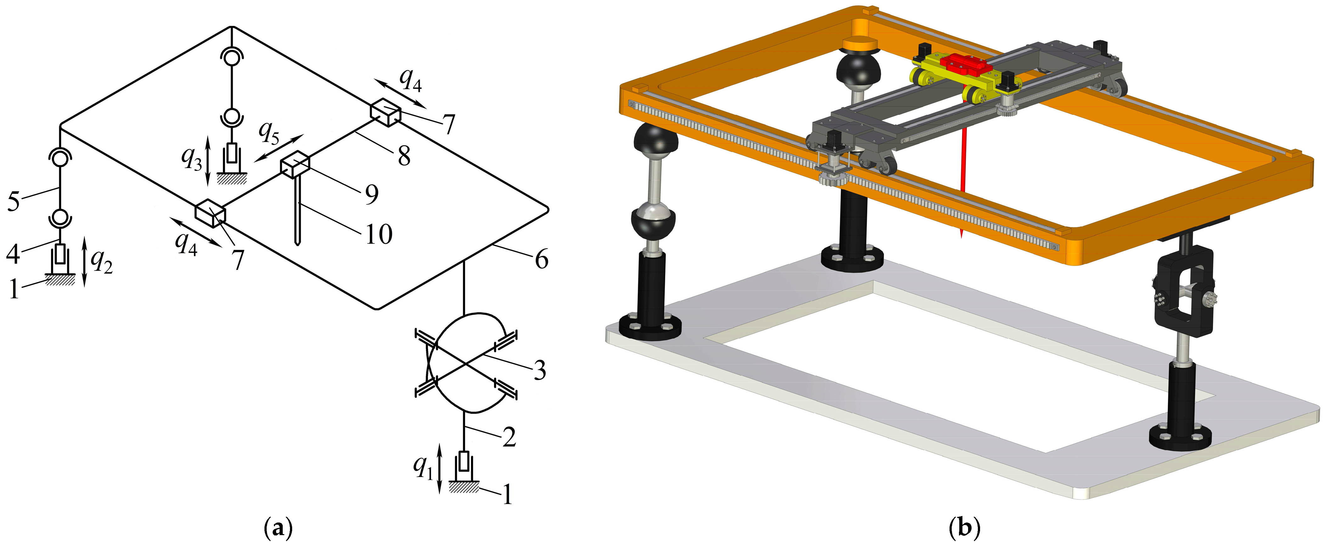
Let us consider the manipulator design. Figure 1 shows its kinematic scheme (Figure 1a) and CAD model (Figure 1b). The manipulator consists of a tripod-like parallel part and a serial part, represented by two carriages moving orthogonally. Figure 1a has the following notations: 1—fixed link (base); 2 and 4—driving links; 3—spider of the universal (Cardan) joint; 5—rod; 6—platform (output link of the parallel part); 7 and 8—rigidly connected links that form a carriage moving along the longitudinal dimension of platform 6; 9—carriage that moves along the transversal dimension of platform 6; 10—end-effector (output link of the serial part and the entire manipulator) mounted rigidly on carriage 9.
Each kinematic chain (leg) of the parallel part has a linear drive that provides displacement , , or . The chain with the universal joint restricts the platform rotation about the axis perpendicular to the spider plane and two translations in any direction orthogonal to the axis of the chain linear drive. Two other chains with spherical joints do not constrain the platform motion. Thus, the parallel part provides platform 6 with one translational and two rotational DOFs. In the serial part, linear drives displace links 7–8 and 9 for and , respectively—the serial part provides end-effector 10 with two translational DOFs in a platform plane relative to platform 6.
In summary, we can specify five independent motions of end-effector 10: three translations and two rotations (3T2R motion pattern), where the parallel part provides one translation and two rotations (1T2R motion pattern) and the serial part adds two translations (2T motion pattern). One should remember that the 3T2R motion pattern can degenerate in singular configurations, which is studied later in this paper.
3. Position Analysis
Though the paper aims at the velocity and singularity study, the position analysis is a necessary preliminary step that provides relations between the coordinates of the links. We addressed this topic in detail in [22], and in the current section, we omit the math and briefly mention the key results essential for the subsequent analysis.
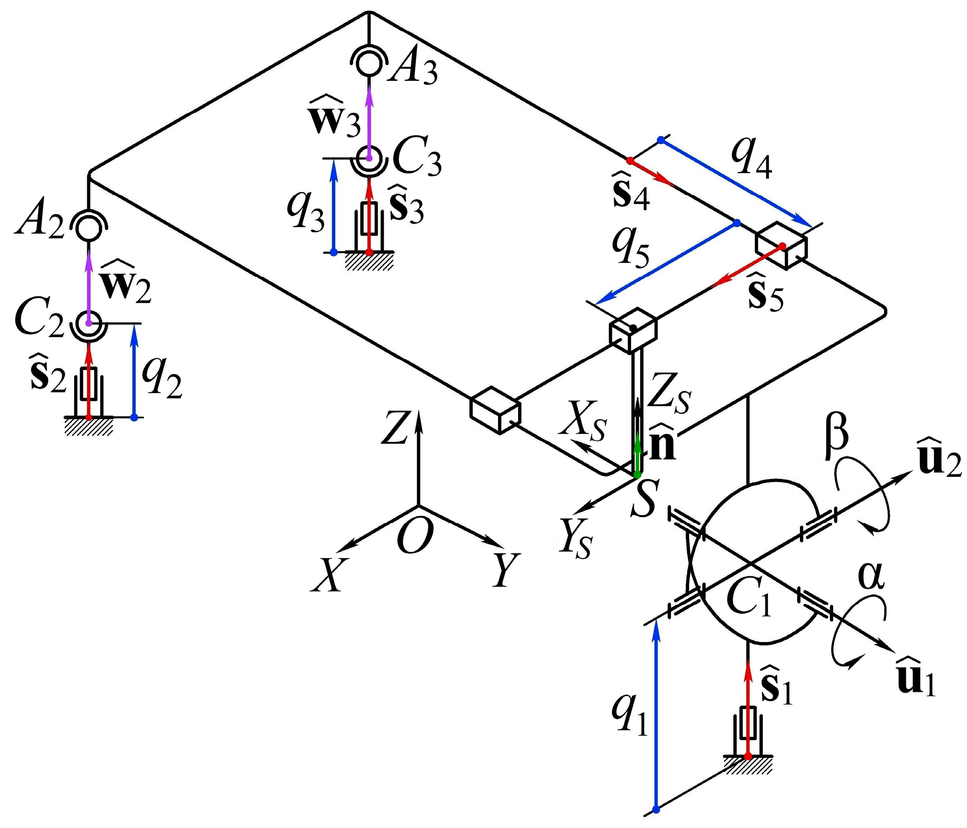
Let us first introduce the following notations (Figure 2):
- is a stationary reference frame attached to the base arbitrarily.
- is a reference frame attached to the end-effector such that axis is directed along the tool (unit vector ) and the remaining axes ( and ) have an arbitrary direction; vector and rotation matrix define the position and orientation of relative to .
- are the actuated coordinates according to the previous section; all these coordinates are measured about the axes defined by unit vectors (in ).
- and are the angles in the universal joint measured about its axes defined by unit vectors and (in ).
Parameters and (or ) describe the end-effector configuration and can define the posture of the entire 5-DOF system: we can express coordinates of all the links as functions of these parameters (solve the inverse kinematics problem). We can also use other sets of parameters to define the manipulator configuration, for example, taking and solving the direct kinematics problem. The choice of and is natural and does not lead to cumbersome calculations [22]. Thus, we assume we are given and , so we can solve the inverse kinematics by the following steps (see [22] for details):
- As the end-effector connects with the platform by two prismatic joints, vector uniquely defines the orientation of the latter. The platform orientation, on the other hand, depends only on two angles and in the universal joint. This condition allows us to express as a function of and and find these angles from the corresponding equations.
- Having found and , we can write a vector loop equation for . This vector depends only on parameters , , and , which we find from the obtained equation.
- Having found , we know the platform configuration relative to . Hence, we know the coordinates of platform spherical joints and relative to the same frame. We can also write coordinates of spherical joints and as functions of and . Coordinates of the spherical joints in each kinematic chain are connected by a known and constant distance between the joints. This allows us to form corresponding equations and find parameters and .
Thus, given the end-effector configuration ( and ), we determined all the parameters necessary to describe coordinates of any manipulator link. In subsequent velocity and singularity analysis, we assume we know all the coordinates involved.
4. Velocity Analysis
Velocity analysis plays a crucial role in manipulator design and control. The major aim of this analysis is to find relations between the velocities of the links, particularly between the end-effector velocity and the drive speeds. There are two prevailing approaches to solve the problem. The first one consists in differentiating constraint equations, obtained during position analysis, with respect to time [23] (p. 153). Though the approach is straightforward, it can lead to cumbersome relations when analyzing complex mechanical systems. An alternative method applies screw theory and considers twists associated with manipulator joints [24]. This technique is more elegant, and it also reveals the physical meaning of the relations obtained, which is important for singularity analysis.
In this paper, we use the second approach mentioned above. Studies [25,26,27] provide comprehensive information about the screw theory, and works [28,29,30,31] show its application for velocity analysis. We encourage a reader novel to the subject of screw theory to have a look at these studies.
4.1. Theory
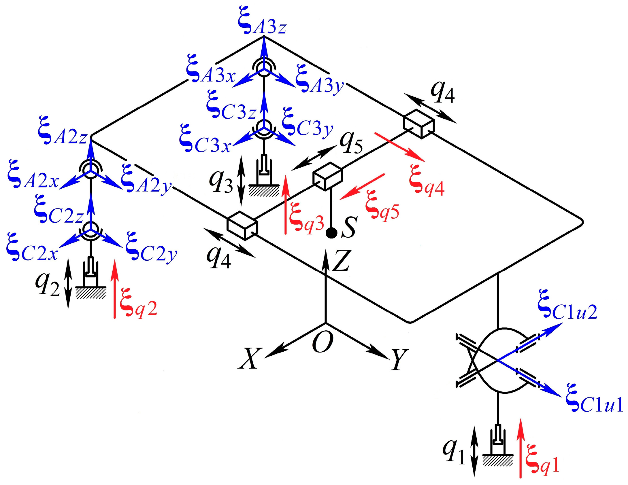
To find a relation between end-effector twist and drive speeds , we should consider (unit) twists of the manipulator joints. Figure 3 shows all these twists: blue arrows designate zero-pitch twists, which correspond to rotations, and red arrows designate infinite-pitch twists, which correspond to translations.
End-effector twist consists of point velocity vector and angular velocity vector ; both vectors are written relative to the frame. Therefore, it is natural to select point as a reference point and write screw coordinates of the joint twists relative to a reference frame, centered at point with axes parallel to the axes of .
First, let us find screw coordinates of infinite-pitch twists (Figure 3), which correspond to the actuated joints. The axis of each twist is collinear with unit vector , so we can write:
Note that vectors , , and are defined by the manipulator design and have known and constant components; vectors and depend on the manipulator configuration and can be obtained through the preceding position analysis.
Zero-pitch twists are and , which correspond to rotations in the universal joint (Figure 3); , , , and , , , , which correspond to rotations in the spherical joints. The axes of the first two twists are collinear with the axes of the universal joint, and these twists have the following coordinates:
where vector defines position of point relative to point ; we know this vector, as well as and , from the position analysis. Moreover, vector has constant components in the considered reference frame.
Axes of the twists corresponding to the spherical joints can be directed arbitrarily. Therefore, for any manipulator configuration, we can assume these axes are always parallel to the coordinate axes. We obtain:
where vectors and define the position of points and , , relative to point ; we know these vectors from the position analysis.
Next, consider three kinematic chains between the end-effector and the base formed by three legs of the parallel manipulator and the platform serial part, which is identical for each chain. We can group the twists of each chain in matrix , :
We can now write the following velocity equation for each :
where vector includes speeds in all passive (unactuated) joints in the -th leg.
Usually, we are not interested in vector . To exclude this vector from the velocity Equation (5), we apply an algorithm based on the reciprocal screw approach [24]. Consider leg 1 first and let be a wrench reciprocal to all twists of except for :
where “” is a reciprocal product of two screws [25] (p. 24).
By taking the reciprocal product of both sides of relation (5) with , we obtain:
Equation (7) includes unknown wrench . To find screw coordinates of this wrench, let us first introduce a new wrench reciprocal to all twists of :
Wrench represents a constraint imposed on the end-effector by leg 1. In any non-singular configuration, ; therefore, we can determine unique wrench (up to a nonzero multiplier) from (8). By observing the leg topology, we see that the end-effector cannot rotate around the axis perpendicular to the axes of the universal joint. Hence, is an infinite-pitch wrench with the following screw coordinates:
As shown in [32], wrench can now be found uniquely (up to a nonzero multiplier) using Equation (6) together with the following condition:
Equations (6) and (10) allow us to compute numerically screw coordinates of each wrench . We can also determine these wrenches geometrically. As and are zero-pitch twists and is an infinite-pitch wrench, these screws describe only rotational freedoms and constraints of the end-effector. Therefore, conditions (6) and (10) imply that any wrench should refer only to translational constraints, i.e., all three are zero-pitch wrenches, whose axes pass through point . Now, let us consider wrench for a moment. A zero-pitch wrench is reciprocal to an infinite-pitch twist if their axes are orthogonal [25] (p. 25); therefore, to satisfy condition (6), the axis of must be orthogonal to the axes of and . We can apply the same logic to and and calculate coordinates of all these wrenches as follows:
Let us now consider leg , , and rewrite Equation (5):
where
Using the same approach as before, we can define the wrench reciprocal to all twists of except for and obtain the following relation:
In any nonsingular configuration, , and there always exists a linear dependence between the twists of the leg spherical joints. Therefore, we can uniquely determine wrench (up to a nonzero multiplier) and calculate its screw coordinates with ease. It is also clear that should be a zero-pitch wrench, whose axis passes through points and , i.e.,
where is a unit vector parallel to line (Figure 2); we know this vector from the position analysis.
To visualize the results obtained so far, Figure 4 shows all the wrenches calculated above for a general manipulator configuration.
Finally, using relations (7) and (13), we exclude all from Equation (5) and rewrite it as follows (the right side of the equation below overloads the reciprocal product notation “∘,” but we hope the meaning is clear from the context):
As the screw coordinates of all twists and wrenches can be calculated from the formulae devised throughout this section, Equation (15) allows us to solve a forward or inverse velocity problem and analyze singular configurations of the manipulator.
We should mention one more thing about Equation (15). Suppose we are given end-effector trajectory and and have to calculate actuator speeds , where is the time. The right side of Equation (15) includes end-effector twist . Linear velocity is a time derivative of vector , i.e., , and we can set it explicitly. To obtain angular velocity , we can first write the following expression [33] (p. 20):
where is a skew-symmetric matrix representation of vector ; is a time derivative of vector , which we can also determine explicitly.
Expression (16) represents a system of three linear equations with respect to unknown components of . In addition, 3 × 3 skew-symmetric matrices have rank two [33] (p. 22); therefore, we cannot use (16) to find unique . To obtain the third independent equation, we can equate the last rows of both sides of (15), concerning (9):
Any two equations of (16) with Equation (17) represent a system of three (independent) linear equations, which we can use to calculate .
4.2. Numerical Example
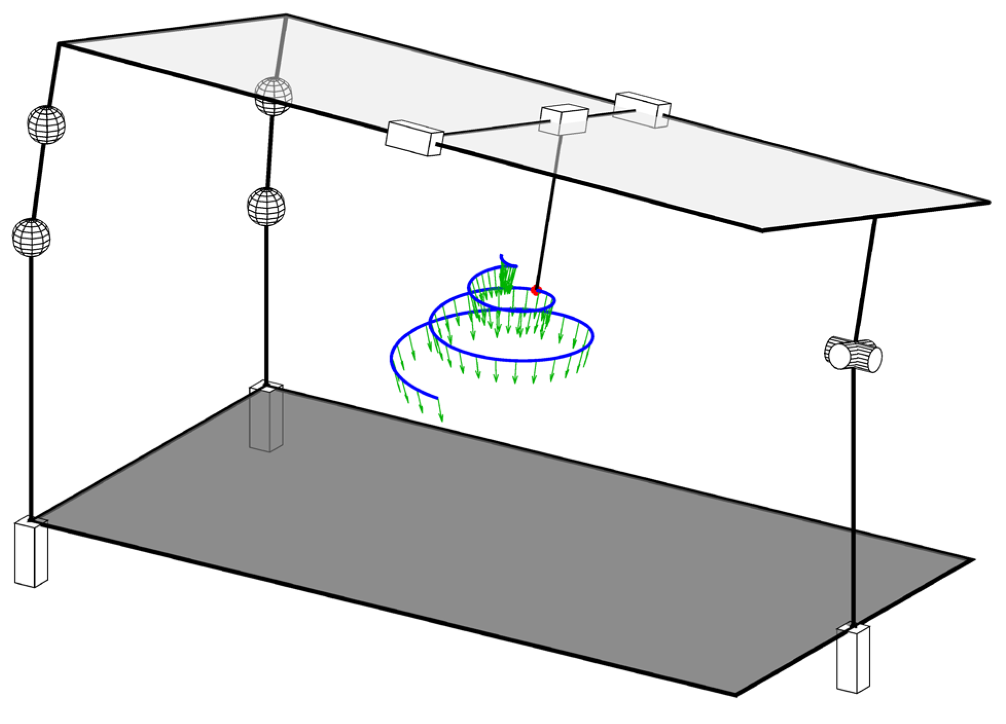
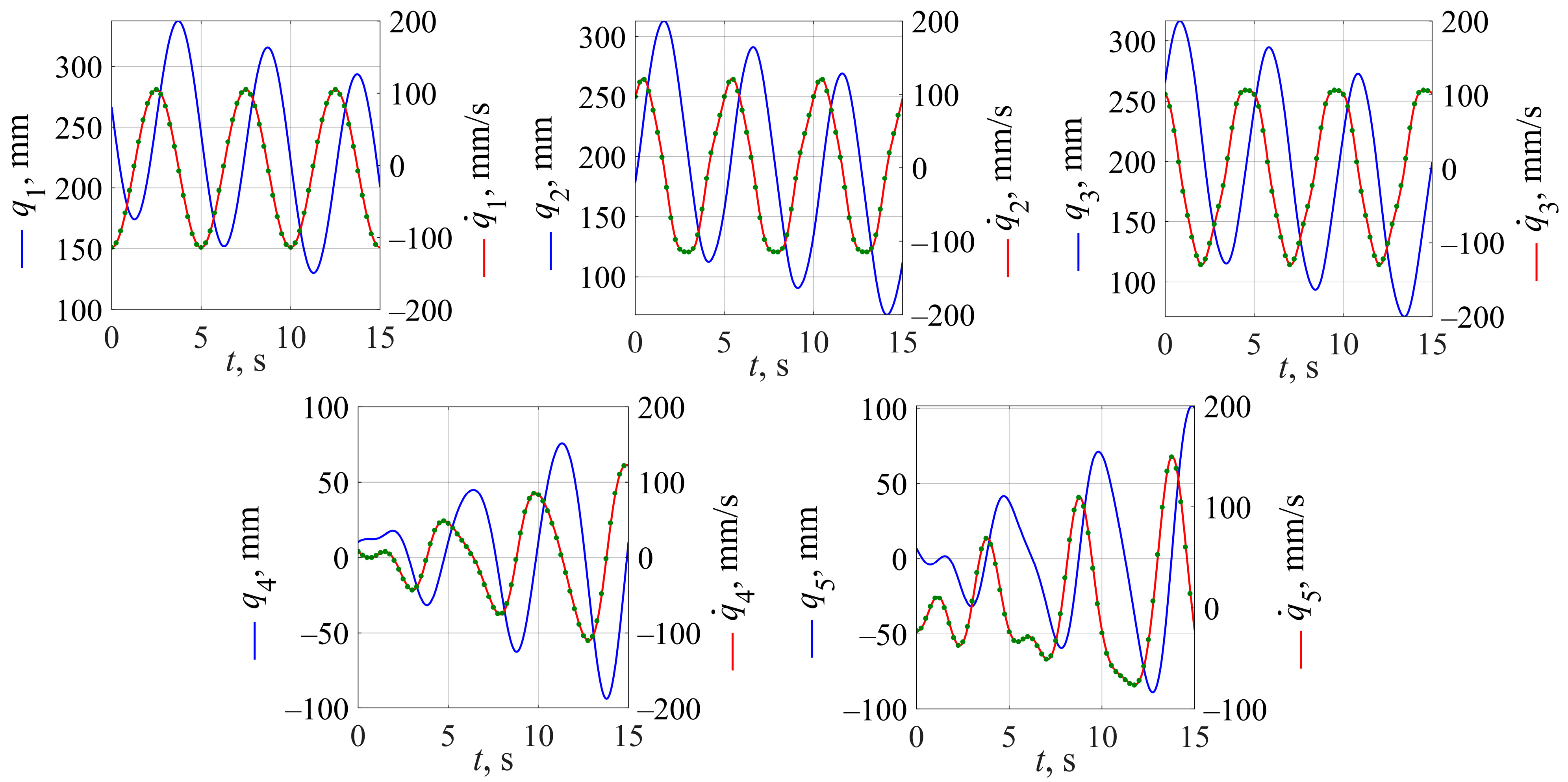
Let us consider an example of velocity analysis when we have to find actuator speeds given the end-effector motion. We examine the manipulator with the same geometrical parameters as in [22], and we suppose the end-effector follows a spiral-helical trajectory also studied earlier in [22]:
Trajectory (18) corresponds to three revolutions of point about the axis of the frame (Figure 5). Both radial and axial pitches of the curve equal 30 mm. At the same time, the end-effector forms an angle of 15° with the axis during the motion. We consider this (arbitrarily selected) trajectory to verify the developed techniques for a general case, when the end-effector varies all its coordinates during the motion.
We simulated the proposed algorithm using the MATLAB package, and Figure 6 shows the computed actuator speeds (red lines). We also calculated these speeds by a numerical differentiation (green dots) of actuated coordinates (blue lines), obtained from the preceding inverse kinematics. Both results coincide completely, which verifies the suggested method.
5. Singularity Analysis
Singularity analysis aims to detect manipulator configurations where it loses or attains DOFs or even changes its motion type. Such configurations should be avoided for proper manipulator performance, and various authors have proposed different approaches to classify and determine singularities [34,35,36,37].
In this section, we use the results obtained in the previous section to discuss two common types of singularities: serial singularities when the end-effector loses a DOF and parallel singularities when it gains an additional (uncontrolled) DOF [38]. Constraint singularities [39] are not possible for this manipulator, since only one leg imposes constraints on the moving platform.
5.1. Serial Singularities
The condition for this type of singularity is that the matrix on the left side of Equation (15) becomes rank-deficient [34]. This 6 × 5 matrix has an upper triangular structure with the last row full of zeros; hence, it will lose its rank if at least one element on the main diagonal equals zero.
Let us first consider the first, fourth, and fifth rows of the matrix. Given Equations (1) and (11), we can write the following conditions:
Any condition from (19) will be satisfied if a parallelepiped formed by vectors , , and degenerates. As, by the manipulator design, vector has a constant direction and vectors and are orthogonal to each other, this situation is only possible if the platform is tilted such that becomes parallel to a plane spanned by and (Figure 7a). The end-effector loses its ability to translate along direction , i.e., perpendicular to the plane mentioned above.
Next, we consider one of the two remaining conditions concerning Equation (14):
Conditions (20) are satisfied if or is perpendicular to or , respectively. Figure 7b shows such a case for leg 2. In this case, the platform loses one DOF because there arises a zero-pitch wrench similar to , which constrains the platform translation parallel to vector . Hence, the end-effector will lose one DOF too. If we want to find its remaining DOFs, we should first determine two twists, which define platform motion, and then augment them with twists and . The wrench system reciprocal to these four twists will define two constraints on the end-effector motion.
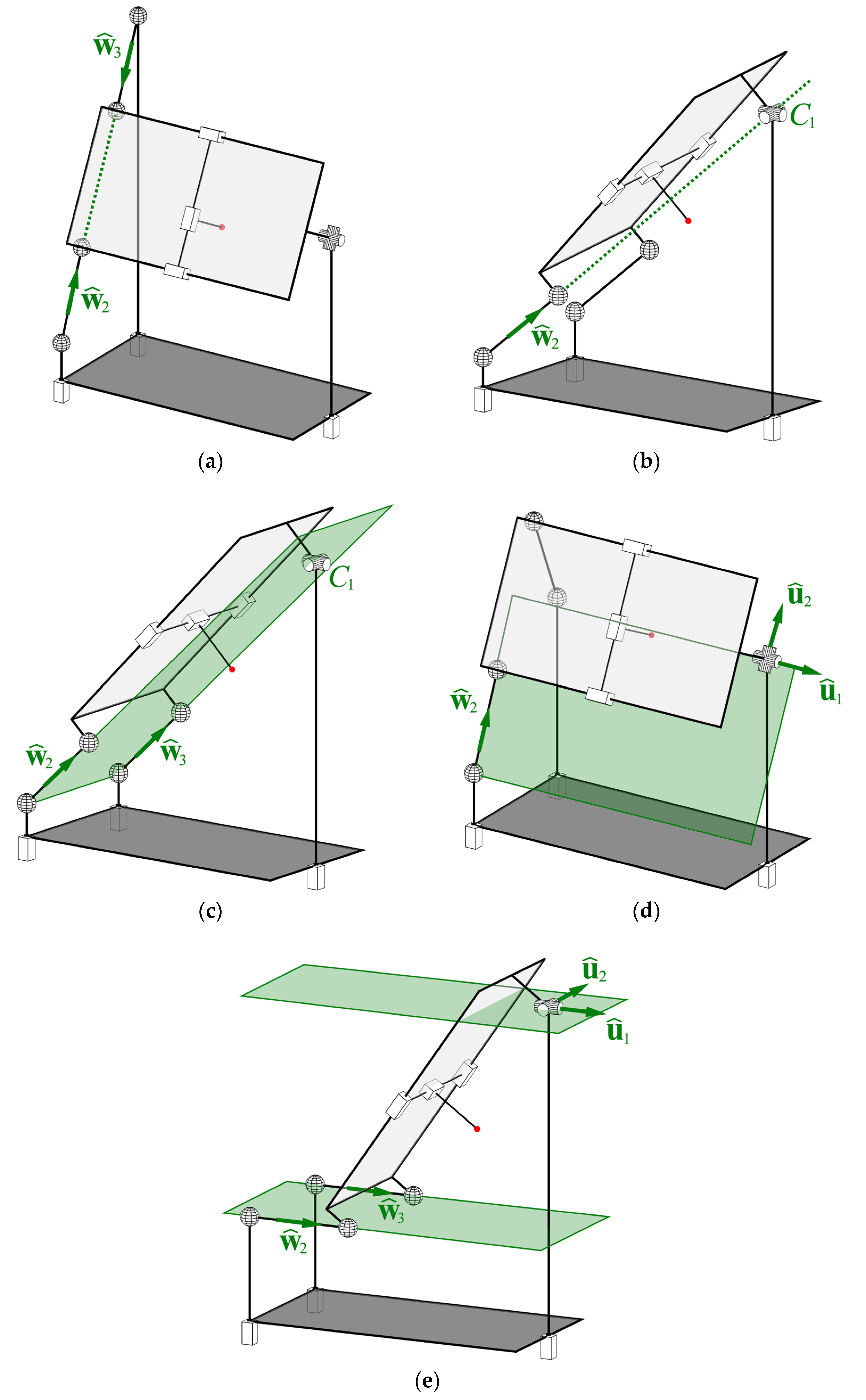
5.2. Parallel Singularities
These singularities occur when the matrix on the right side of Equation (15) loses its rank [34], i.e., when wrenches that form this matrix are linearly dependent. We can also treat this condition as follows: the end-effector will gain an uncontrolled motion () when all its drives are stopped ().
Let us first focus on the 3-DOF parallel part of the manipulator (we explain the reasons later) and assume that its actuated pairs, which correspond to , , are stopped. In this case, leg 1 provides the platform with two rotational DOFs, which come from the universal joint, and therefore imposes four constraints (three translational and one rotational). We can represent these constraints by four wrenches: three (linearly independent) zero-pitch wrenches with axes passing through point and one infinite pitch wrench . Legs 2 and 3 impose constraints described by zero-pitch wrenches and , respectively. As all translational movements of the platform are prevented by three zero-pitch wrenches mentioned above, and should only constrain two rotational DOFs not blocked by . In other words, if we calculate screw coordinates of and with being the reference point, the moment parts (last three components) of these wrenches along with the vector defining the axis of should be linearly independent and span a three-dimensional constraint space. In the most general case, this condition can be violated when the three vectors mentioned above lie in the same plane, i.e.,
where and are vectors from point to any point on a line spanned by vector or , respectively.
The platform will attain an uncontrolled rotation about the axis, which passes through point orthogonally to the plane mentioned above. We can mention several particular cases:
- and are collinear (Figure 8a): and are linearly dependent, and their moment parts are collinear.
- (or ) is on a line passing through point (Figure 8b): (or ) has a zero moment part.
- and lie in a plane passing through point (Figure 8c): the moment parts of and are collinear.
- (or ) lie in the spider plane, spanned by vectors and (Figure 8d): the moment part of (or ) is collinear with the axis of .
- and are parallel and lie in a plane parallel to the spider plane (Figure 8e): the moment parts of and and the axis of lie in a common plane.
The above cases describe possible parallel singularities of the 3-DOF parallel manipulator. In cases 2 and 4, the condition can hold for both and simultaneously: the platform will attain two uncontrolled rotational DOFs about any axes, which pass through point and lie in the spider plane.
Actually, the parallel singularities mentioned above correspond not only to the 3-DOF parallel part but for the entire manipulator. One can argue that we did not consider wrenches , , and , presented in (15), but introduced three other zero-pitch wrenches in point . The reason for doing this is that translational constraints imposed by leg 1 are determined by the leg topology and do not depend on the platform orientation. Technically, in a nonsingular configuration, , , and can also be used to analyze parallel singularities. On the other hand, if , , and are linearly dependent, condition (19) will be satisfied, and the matrix on the left side of Equation (15) will lose its rank. Such a configuration, however, is not a parallel singularity, and there will be no uncontrolled instantaneous motion of the platform.
6. Discussion
Screw theory allows us to address both velocity and singularity analyses of the hybrid spatial manipulator by simple expressions, obtained mainly by inspection and with no complicated numerical calculations. For comparison, we could find matrices in the velocity Equation (15) by differentiating the kinematic constraint equations [22], but this approach would require some tricky manipulations with the vector loop expressions, which are unnecessary in the presented procedure. Moreover, in contrast to the formal numerical procedures, the applied method reveals the geometrical nature of singular configurations, which could be difficult to interpret if we directly computed and analyzed the matrix determinants in Equation (15). This geometrical insight is useful for better understanding of the manipulator performance.
During the velocity analysis, we obtained the relation that connects drive speeds and end-effector twist . Some designing tasks may also require speeds in unactuated joints, i.e., vectors in Equation (5). We can always include these speeds in our study by selecting wrenches that are not reciprocal to the twist in the passive joint that we are interested in. This approach allows us to compute speed in any joint of the manipulator.
During the singularity analysis, we established several conditions that correspond to serial and parallel singularities. In practice, we should check these conditions when planning motion trajectories to guarantee proper manipulator performance. Note that we can also avoid some singular configurations by suitable mechanical design. For example, singularities given in Figure 7a and Figure 8a,e will most likely be beyond the manipulator workspace because of the joint constraints. Nevertheless, it is always desirable to analyze closeness to singularities [40] because the manipulator can lose its stiffness and accuracy and may require additional efforts from its actuators when it is nearby a singular posture.
7. Conclusions
This article has expanded the previous research performed on the 5-DOF 3T2R parallel-serial (hybrid) manipulator. After a brief discussion of the manipulator design and its position analysis, the paper has presented an approach for velocity and singularity analysis based on the screw theory.
First, we considered the unit twists of each manipulator joint and obtained closed-form expressions for actuation and constraint wrenches using the reciprocal screw method. Having determined screw coordinates of these twists and wrenches, we formed a system of velocity equations, which relates the end-effector twist to the drive speeds. To demonstrate the proposed techniques, we performed the inverse velocity analysis for a predefined spiral-helical trajectory. We found the values of the drive speeds and verified the results by comparing them to the values obtained through the numerical differentiation.
Next, we investigated serial and parallel singular configurations of the manipulator by analyzing wrench systems obtained during the velocity analysis. We established several conditions for both types of singularities and provided corresponding mathematical relations between the screw coordinates of the wrenches. We also considered two examples of the serial singularities and five examples of the parallel ones and gave a visual representation for each case.
The material presented in the current study is essential for manipulator control and motion planning. Let us also mention several directions for future research. The first one, based on the performed velocity analysis, includes a dynamic study of the manipulator that will require the determination of accelerations of its links and composing equations of motions. The second possible direction is an optimal design problem: we can use the results of the singularity analysis to identify manipulator geometrical parameters that provide the required accuracy and stiffness and guarantee that the manipulator does not attain any singular configuration within its workspace. The results obtained in this paper can also be extended to other hybrid manipulators.
Author Contributions
Conceptualization, P.L., A.A. and A.F.; methodology, P.L., A.A., A.F. and T.E.; software, P.L., A.A. and A.F.; validation, P.L., A.A. and A.F.; formal analysis, P.L., A.A. and A.F.; investigation, P.L., A.A. and A.F.; resources, P.L., A.A. and A.F.; writing—original draft preparation, P.L., A.A. and A.F.; writing—review and editing, P.L., A.A., A.F. and T.E.; visualization, P.L., A.A. and A.F.; supervision, P.L., A.A. and A.F.; project administration, P.L., A.A. and A.F.; funding acquisition, P.L., A.A. and A.F. All authors have read and agreed to the published version of the manuscript.
Funding
This research was supported by the Russian Science Foundation (RSF) under grant No. 21-79-10409, https://rscf.ru/project/21-79-10409/ (accessed on 10 April 2022).
Institutional Review Board Statement
Not applicable.
Informed Consent Statement
Not applicable.
Data Availability Statement
The data presented in this study are available on request from the corresponding author.
Conflicts of Interest
The authors declare that they have no conflict of interest.
References
- Kumar, S.; Wöhrle, H.; Fernández, J.G.; Müller, A.; Kirchner, F. A survey on modularity and distributivity in series-parallel hybrid robots. Mechatronics 2020, 68, 102367. [Google Scholar] [CrossRef]
- Wen, K.; Harton, D.; Laliberté, T.; Gosselin, C. Kinematically redundant (6+3)-dof hybrid parallel robot with large orientational workspace and remotely operated gripper. In Proceedings of the 2019 IEEE International Conference on Robotics and Automation, Montreal, QC, Canada, 20–24 May 2019; pp. 1672–1678. [Google Scholar] [CrossRef]
- Liu, Q.; Huang, T. Inverse kinematics of a 5-axis hybrid robot with non-singular tool path generation. Robot. Comp.-Integr. Manuf. 2019, 56, 140–148. [Google Scholar] [CrossRef] [Green Version]
- Carbone, G.; Ceccarelli, M. A stiffness analysis for a hybrid parallel-serial manipulator. Robotica 2004, 22, 567–576. [Google Scholar] [CrossRef]
- Lai, Y.-L.; Liao, C.-C.; Chao, Z.-G. Inverse kinematics for a novel hybrid parallel–serial five-axis machine tool. Robot. Comp.-Integr. Manuf. 2018, 50, 63–79. [Google Scholar] [CrossRef]
- Oba, Y.; Kakinuma, Y. Simultaneous tool posture and polishing force control of unknown curved surface using serial-parallel mechanism polishing machine. Precis. Eng. 2017, 49, 24–32. [Google Scholar] [CrossRef]
- Tanev, T.K. Kinematics of a hybrid (parallel–serial) robot manipulator. Mech. Mach. Theory 2000, 35, 1183–1196. [Google Scholar] [CrossRef]
- Moosavian, S.A.A.; Pourreza, A.; Alipour, K. Kinematics and dynamics of a hybrid serial-parallel mobile robot. In Proceedings of the 2009 IEEE International Conference on Robotics and Automation, Kobe, Japan, 12–17 May 2009; pp. 1358–1363. [Google Scholar] [CrossRef]
- Zheng, X.Z.; Bin, H.Z.; Luo, Y.G. Kinematic analysis of a hybrid serial-parallel manipulator. Int. J. Adv. Manuf. Technol. 2004, 23, 925–930. [Google Scholar] [CrossRef]
- Nazari, A.A.; Moosavian, S.A.A.; Hasani, A. Kinematics analysis, dynamic modeling and verification of a CRRR 3-DOF spatial parallel robot. In Proceedings of the 2nd International Conference on Control, Instrumentation and Automation, Shiraz, Iran, 27–29 December 2011; pp. 1067–1073. [Google Scholar] [CrossRef]
- Kucuk, S.; Gungor, B.D. Inverse kinematics solution of a new hybrid robot manipulator proposed for medical purposes. In Proceedings of the 2016 Medical Technologies National Congress (TIPTEKNO), Antalya, Turkey, 27–29 October 2016; pp. 1–4. [Google Scholar] [CrossRef]
- Zhang, D.-S.; Xu, Y.-D.; Yao, J.-T.; Zhao, Y.-S. Analysis and optimization of a spatial parallel mechanism for a new 5-DOF hybrid serial-parallel manipulator. Chin. J. Mech. Eng. 2018, 31, 54. [Google Scholar] [CrossRef] [Green Version]
- Xu, P.; Cheung, C.-F.; Li, B.; Ho, L.-T.; Zhang, J.-F. Kinematics analysis of a hybrid manipulator for computer controlled ultra-precision freeform polishing. Robot. Comp.-Integr. Manuf. 2017, 44, 44–56. [Google Scholar] [CrossRef]
- Gim, K.G.; Kim, J.; Yamane, K. Design of a serial-parallel hybrid leg for a humanoid robot. In Proceedings of the 2018 IEEE International Conference on Robotics and Automation, Brisbane, Australia, 21–25 May 2018; pp. 6076–6081. [Google Scholar] [CrossRef]
- Milutinović, M.; Slavković, N.; Milutinović, D. Kinematic modelling of hybrid parallel-serial five-axis machine tool. FME Trans. 2013, 41, 1–10. Available online: https://scholar.google.ru/scholar?cluster=10660065093727811310 (accessed on 10 April 2022).
- My, C.A.; Hoan, V.M. Kinematic and dynamic analysis of a serial manipulator with local closed loop mechanisms. Vietnam J. Mech. 2019, 41, 141–155. [Google Scholar] [CrossRef]
- Nasseri, M.A.; Eder, M.; Eberts, D.; Nair, S.; Maier, M.; Zapp, D.; Lohmann, C.P.; Knoll, A. Kinematics and dynamics analysis of a hybrid parallel-serial micromanipulator designed for biomedical applications. In Proceedings of the 2013 IEEE/ASME International Conference on Advanced Intelligent Mechatronics, Wollongong, Australia, 9–12 July 2013; pp. 293–299. [Google Scholar] [CrossRef] [Green Version]
- Simas, H.; Di Gregorio, R. Position analysis, singularity loci and workspace of a novel 2PRPU Schoenflies-motion generator. Robotica 2019, 37, 141–160. [Google Scholar] [CrossRef]
- Rakhodaei, H.R.; Rastegarpanah, A.; Ding, C.D.; Saadat, M.S. Free singularity path planning of hybrid parallel robot. In Proceedings of the 11th International Conference on Manufacturing Research, Cranfield, UK, 19–20 September 2013; pp. 313–318. Available online: https://scholar.google.ru/scholar?cluster=4732131641093736040 (accessed on 10 April 2022).
- Amine, S.; Caro, S.; Wenger, P. Constraint and singularity analysis of the Exechon. App. Mech. Mater. 2012, 162, 141–150. [Google Scholar] [CrossRef]
- Ma, G.; Chen, Y.; Yao, Y.; Gao, J. Kinematics and singularity analysis of a four-degree-of-freedom serial-parallel hybrid manipulator. J. Robot. Mechatron. 2017, 29, 520–527. [Google Scholar] [CrossRef]
- Antonov, A.; Fomin, A.; Glazunov, V.; Kiselev, S.; Carbone, G. Inverse and forward kinematics and workspace analysis of a novel 5-DOF (3T2R) parallel–serial (hybrid) manipulator. Inter. J. Adv. Robot. Syst. 2021, 18, 1–14. [Google Scholar] [CrossRef]
- Merlet, J.-P. Parallel Robots, 2nd ed.; Springer: Dordrecht, The Netherlands, 2006. [Google Scholar] [CrossRef]
- Mohamed, M.G.; Duffy, J. A direct determination of the instantaneous kinematics of fully parallel robot manipulators. J. Mech. Trans. Autom. 1985, 107, 226–229. [Google Scholar] [CrossRef]
- Kong, X.; Gosselin, C.M. Type Synthesis of Parallel Mechanisms; Springer: Berlin/Heidelberg, Germany, 2007. [Google Scholar] [CrossRef]
- Huang, Z.; Li, Q.; Ding, H. Theory of Parallel Mechanisms; Springer: Dordrecht, The Netherlands, 2013. [Google Scholar] [CrossRef]
- Sun, T.; Yang, S.; Lian, B. Finite and Instantaneous Screw Theory in Robotic Mechanism; Springer: Singapore, 2020. [Google Scholar] [CrossRef]
- Rodriguez-Leal, E.; Dai, J.S.; Pennock, G.R. A study of the instantaneous kinematics of the 5-RSP parallel mechanism using screw theory. In Advances in Reconfigurable Mechanisms and Robots I; Dai, J., Zoppi, M., Kong, X., Eds.; Springer: London, UK, 2012; pp. 355–369. [Google Scholar] [CrossRef]
- Guo, S.; Wang, C.; Qu, H.; Fang, Y. A novel 4-RRCR parallel mechanism based on screw theory and its kinematics analysis. Proc. Inst. Mech. Eng. C J. Mech. Eng. Sci. 2013, 227, 2039–2048. [Google Scholar] [CrossRef]
- Lescano, S.; Zlatanov, D.; Rakotondrabe, M.; Andreff, N. Kinematic analysis of a meso-scale parallel robot for laser phonomicrosurgery. In Interdisciplinary Applications of Kinematics; Kecskeméthy, A., Geu Flores, F., Eds.; Springer: Cham, Switzerland, 2015; pp. 127–135. [Google Scholar] [CrossRef] [Green Version]
- Kang, L.; Kim, W.; Yi, B.-J. Modeling and analysis of parallel mechanisms with both kinematic and actuation redundancies via screw theory. J. Mech. Robot. 2017, 9, 061007. [Google Scholar] [CrossRef]
- Laryushkin, P.; Glazunov, V.; Erastova, K. On the maximization of joint velocities and generalized reactions in the workspace and singularity analysis of parallel mechanisms. Robotica 2019, 37, 675–690. [Google Scholar] [CrossRef]
- Bottema, O.; Roth, B. Theoretical Kinematics, reprint of 1979 ed.; Dover: New York, NY, USA, 1990; Available online: https://scholar.google.ru/scholar?cluster=7729442652911673935 (accessed on 10 April 2022).
- Gosselin, C.; Angeles, J. Singularity analysis of closed-loop kinematic chains. IEEE Trans. Robot. Autom. 1990, 6, 281–290. [Google Scholar] [CrossRef]
- Zlatanov, D.; Fenton, R.G.; Benhabib, B. Identification and classification of the singular configurations of mechanisms. Mech. Mach. Theory 1998, 33, 743–760. [Google Scholar] [CrossRef]
- Conconi, M.; Carricato, M. A new assessment of singularities of parallel kinematic chains. IEEE Trans. Robot. 2009, 25, 757–770. [Google Scholar] [CrossRef]
- Bohigas, O.; Manubens, M.; Ros, L. Singularities of Robot Mechanisms; Springer: Cham, Switzerland, 2017. [Google Scholar] [CrossRef]
- Chablat, D.; Wenger, P. Working modes and aspects in fully parallel manipulators. In Proceedings of the 1998 IEEE International Conference on Robotics and Automation, Leuven, Belgium, 20–20 May 1998; pp. 1964–1969. [Google Scholar] [CrossRef] [Green Version]
- Zlatanov, D.; Bonev, I.A.; Gosselin, C.M. Constraint singularities of parallel mechanisms. In Proceedings of the 2002 IEEE International Conference on Robotics and Automation, Washington, DC, USA, 11–15 May 2002; pp. 496–502. [Google Scholar] [CrossRef]
- Liu, X.-J.; Wu, C.; Wang, J. A new approach for singularity analysis and closeness measurement to singularities of parallel manipulators. J. Mech. Robot. 2012, 4, 041001. [Google Scholar] [CrossRef]
Figure 1.
5-DOF (3T2R) parallel–serial (hybrid) manipulator: (a) structural scheme; (b) CAD model.

Figure 2.
Kinematic analysis of the considered manipulator.

Figure 3.
Joint (unit) twists of the manipulator. Blue arrows designate zero-pitch twists; red arrows designate infinite-pitch twists.
Figure 3.
Joint (unit) twists of the manipulator. Blue arrows designate zero-pitch twists; red arrows designate infinite-pitch twists.

Figure 4.
Wrenches of the manipulator.

Figure 5.
Spiral-helical trajectory for velocity analysis. Green arrows show end-effector orientation.
Figure 5.
Spiral-helical trajectory for velocity analysis. Green arrows show end-effector orientation.

Figure 6.
Results of velocity analysis: blue lines—; red lines— according to the proposed algorithm; green dots— by numerical differentiation of .
Figure 6.
Results of velocity analysis: blue lines—; red lines— according to the proposed algorithm; green dots— by numerical differentiation of .

Figure 7.
Serial singularities: (a) parallelepiped formed by vectors , , and degenerates; (b) is othogonal to .
Figure 7.
Serial singularities: (a) parallelepiped formed by vectors , , and degenerates; (b) is othogonal to .

Figure 8.
Parallel singularities: (a) and are collinear; (b) passes through ; (c) and lie in a plane passing through ; (d) lie in the spider plane, spanned by and ; (e) and are parallel and lie in a plane parallel to the spider plane.
Figure 8.
Parallel singularities: (a) and are collinear; (b) passes through ; (c) and lie in a plane passing through ; (d) lie in the spider plane, spanned by and ; (e) and are parallel and lie in a plane parallel to the spider plane.

Publisher’s Note: MDPI stays neutral with regard to jurisdictional claims in published maps and institutional affiliations. |
© 2022 by the authors. Licensee MDPI, Basel, Switzerland. This article is an open access article distributed under the terms and conditions of the Creative Commons Attribution (CC BY) license (https://creativecommons.org/licenses/by/4.0/).
Share and Cite
MDPI and ACS Style
Laryushkin, P.; Antonov, A.; Fomin, A.; Essomba, T. Velocity and Singularity Analysis of a 5-DOF (3T2R) Parallel-Serial (Hybrid) Manipulator. Machines 2022, 10, 276. https://doi.org/10.3390/machines10040276
AMA Style
Laryushkin P, Antonov A, Fomin A, Essomba T. Velocity and Singularity Analysis of a 5-DOF (3T2R) Parallel-Serial (Hybrid) Manipulator. Machines. 2022; 10(4):276. https://doi.org/10.3390/machines10040276
Chicago/Turabian StyleLaryushkin, Pavel, Anton Antonov, Alexey Fomin, and Terence Essomba. 2022. "Velocity and Singularity Analysis of a 5-DOF (3T2R) Parallel-Serial (Hybrid) Manipulator" Machines 10, no. 4: 276. https://doi.org/10.3390/machines10040276
Note that from the first issue of 2016, this journal uses article numbers instead of page numbers. See further details here.