
Experimental Studies on the Flammability and Fire Hazards of Photovoltaic Modules

Abstract
:1. Introduction
2. Analysis of the Flammability of PV Modules
3. Experimental Section
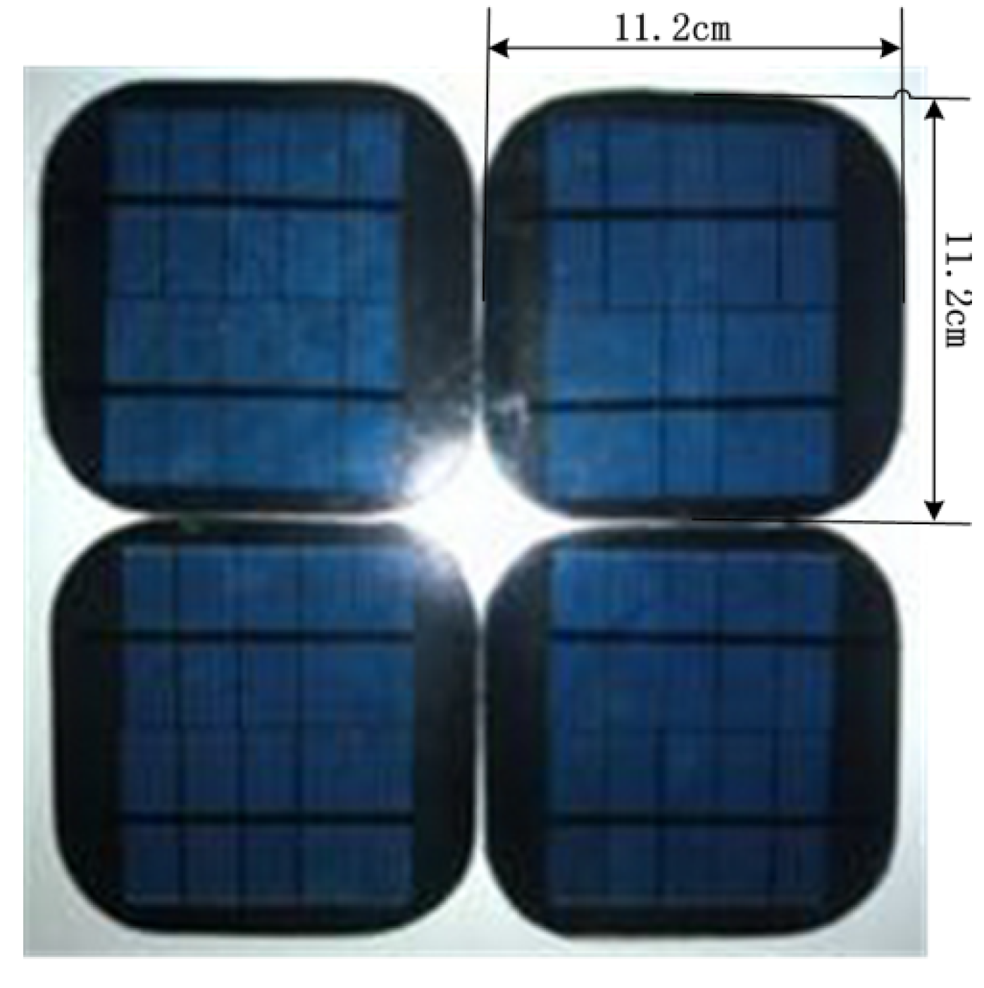
3.1. Materials


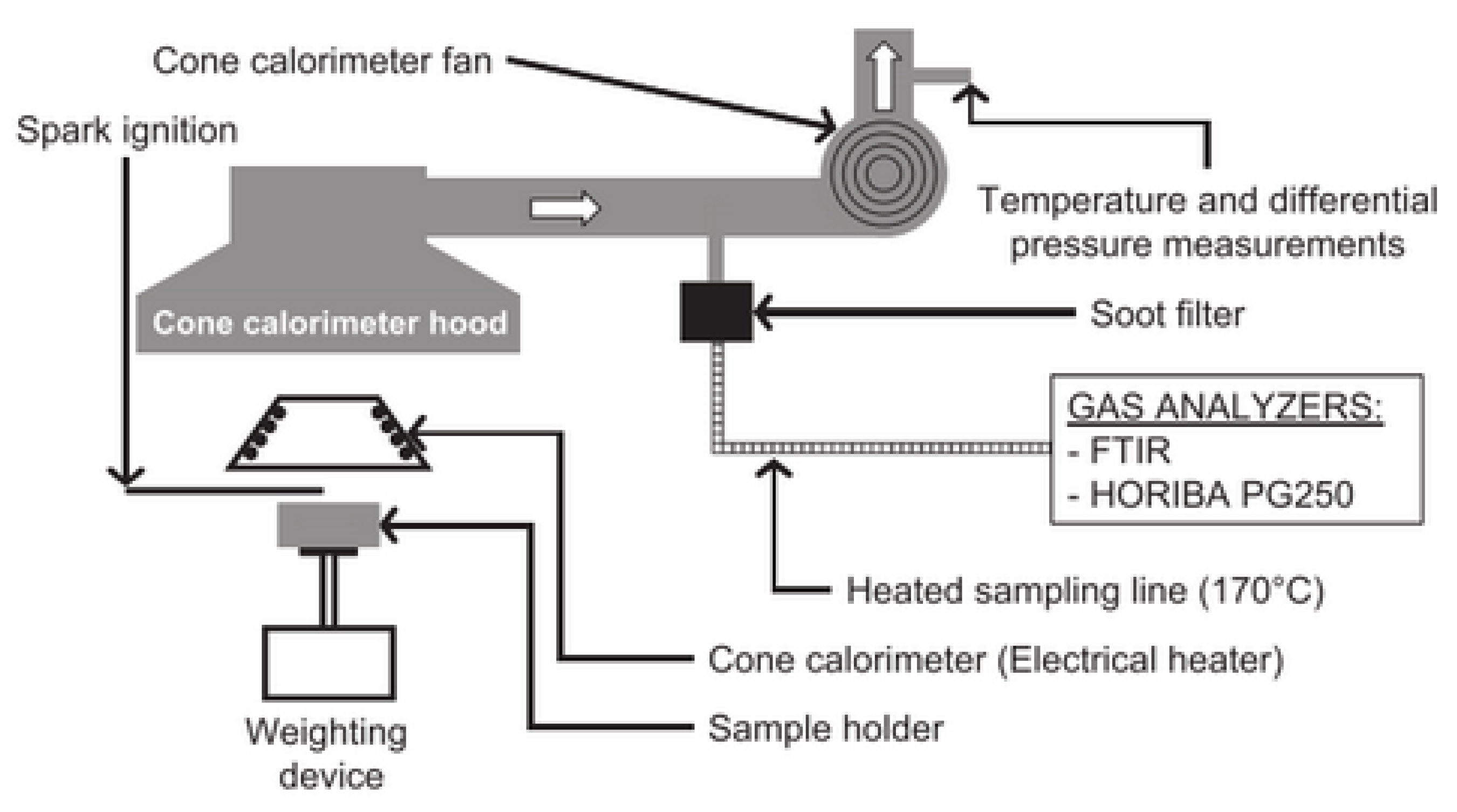
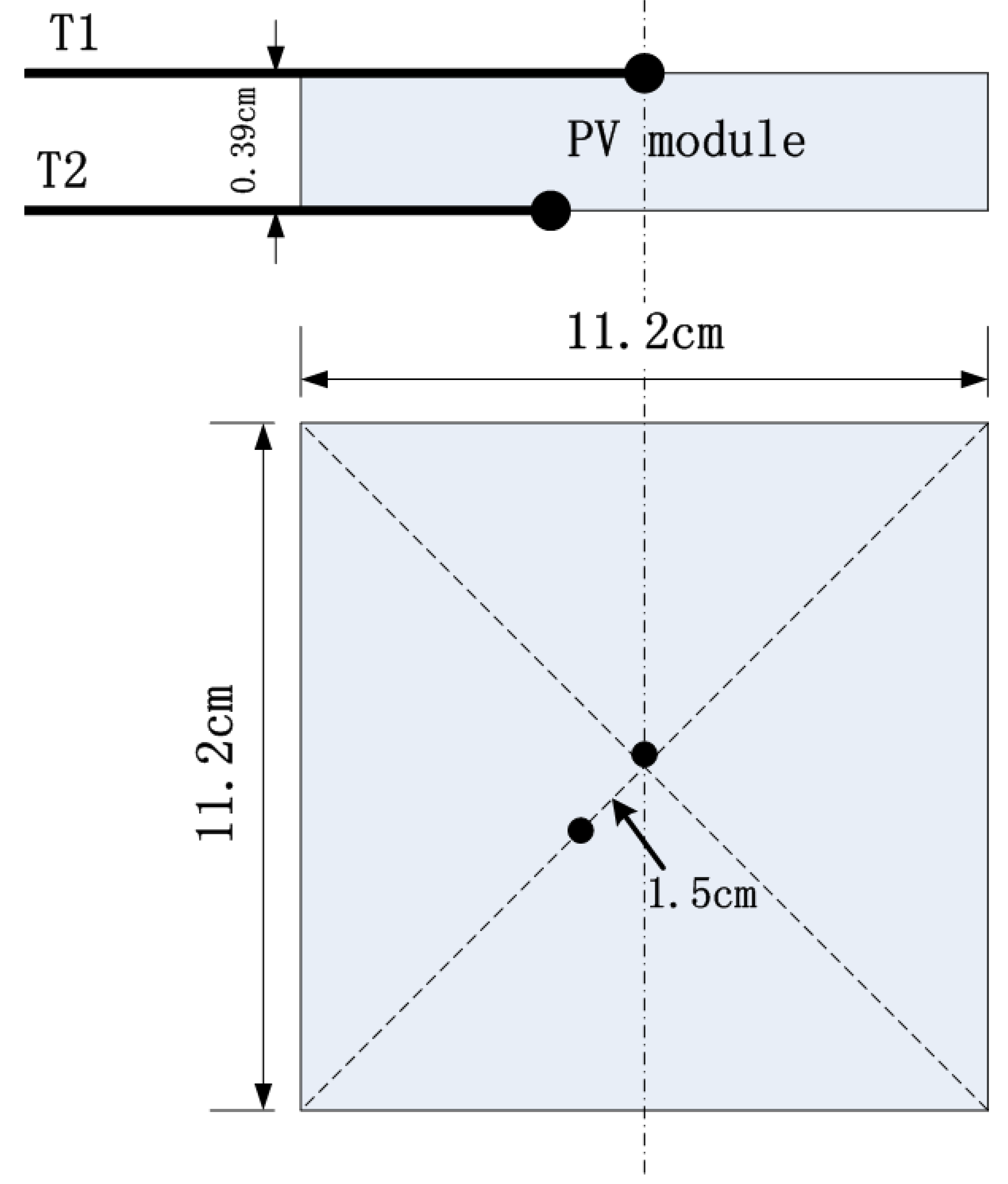
3.2. Test Method

4. Results and Analysis
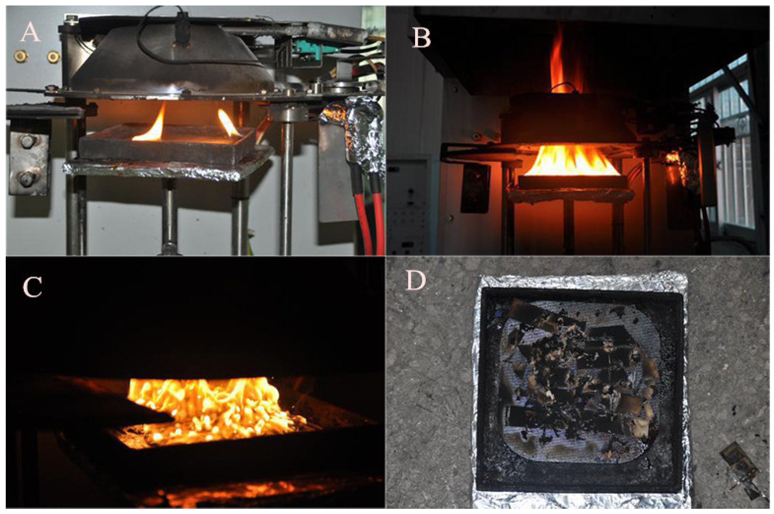
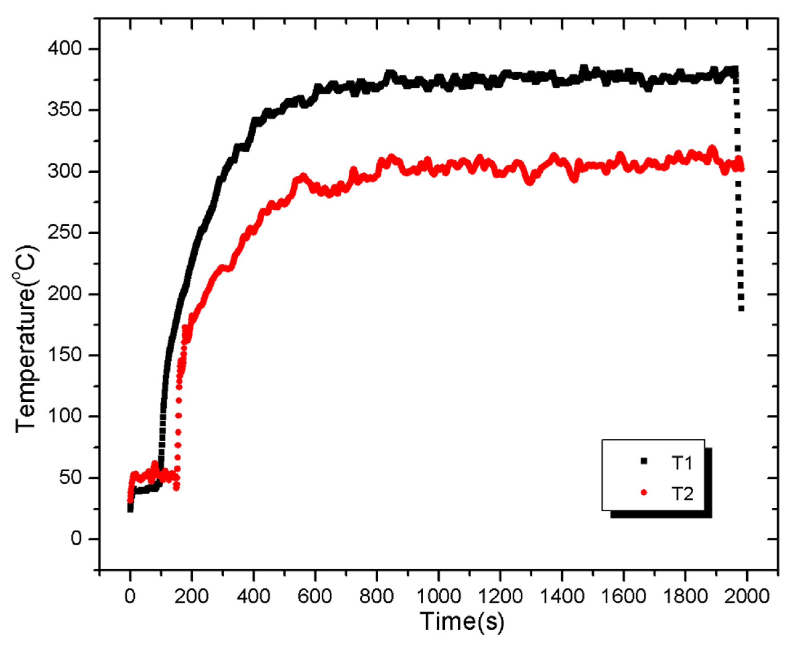
4.1. Experimental Phenomena

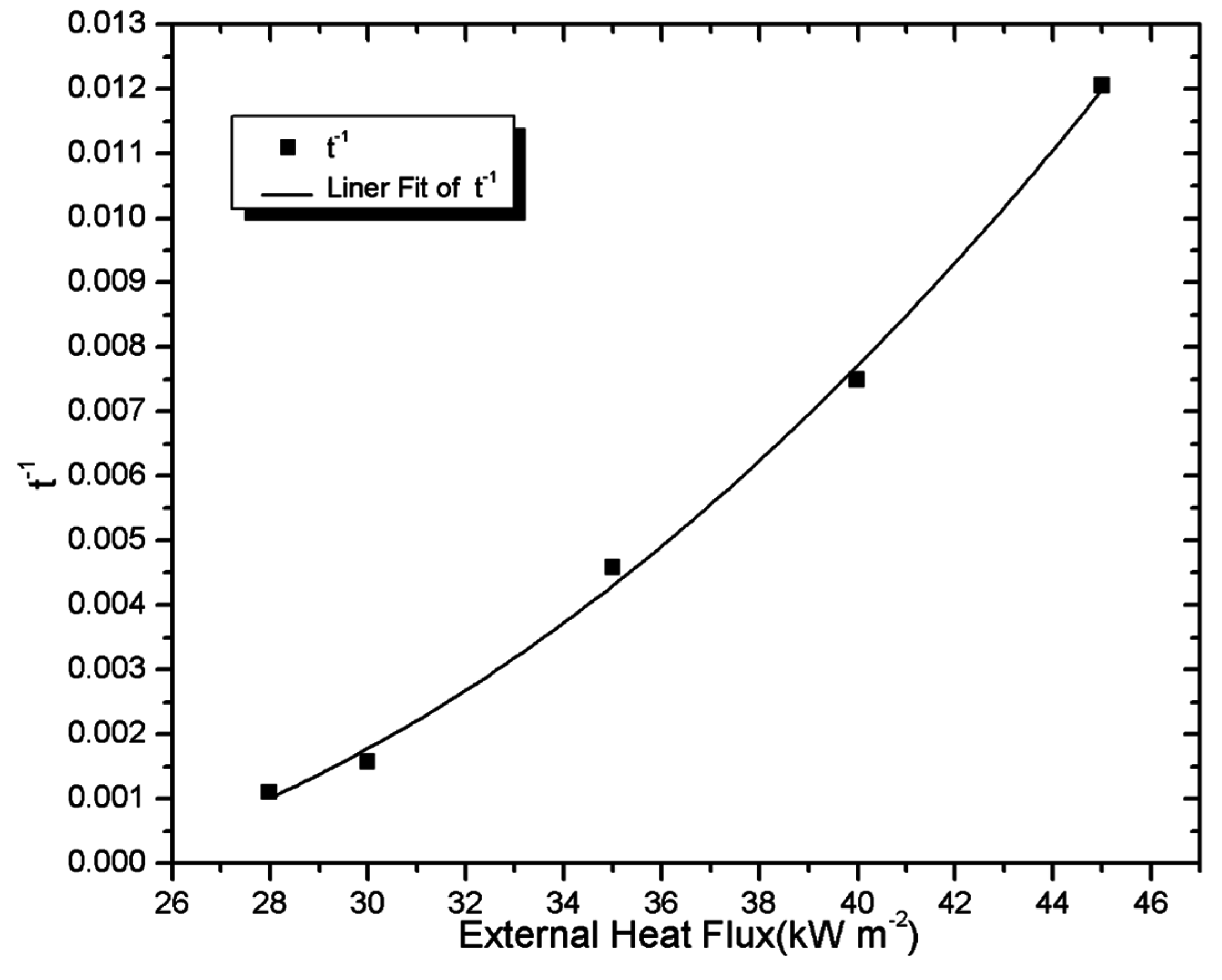
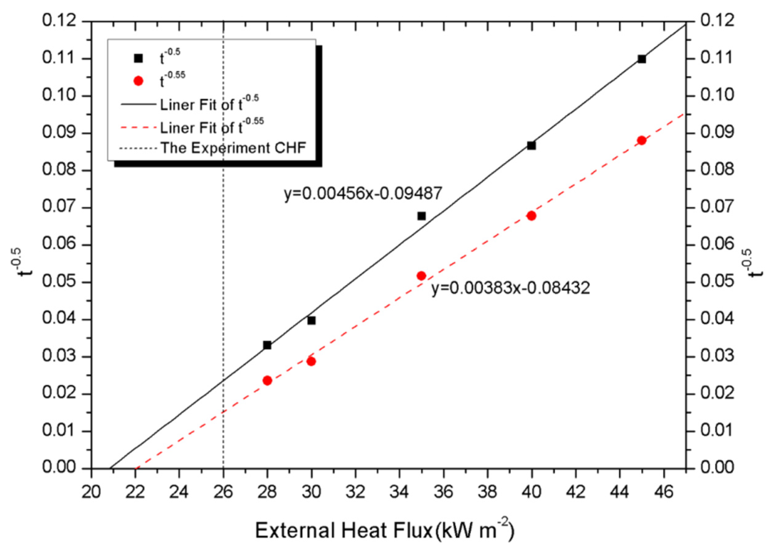
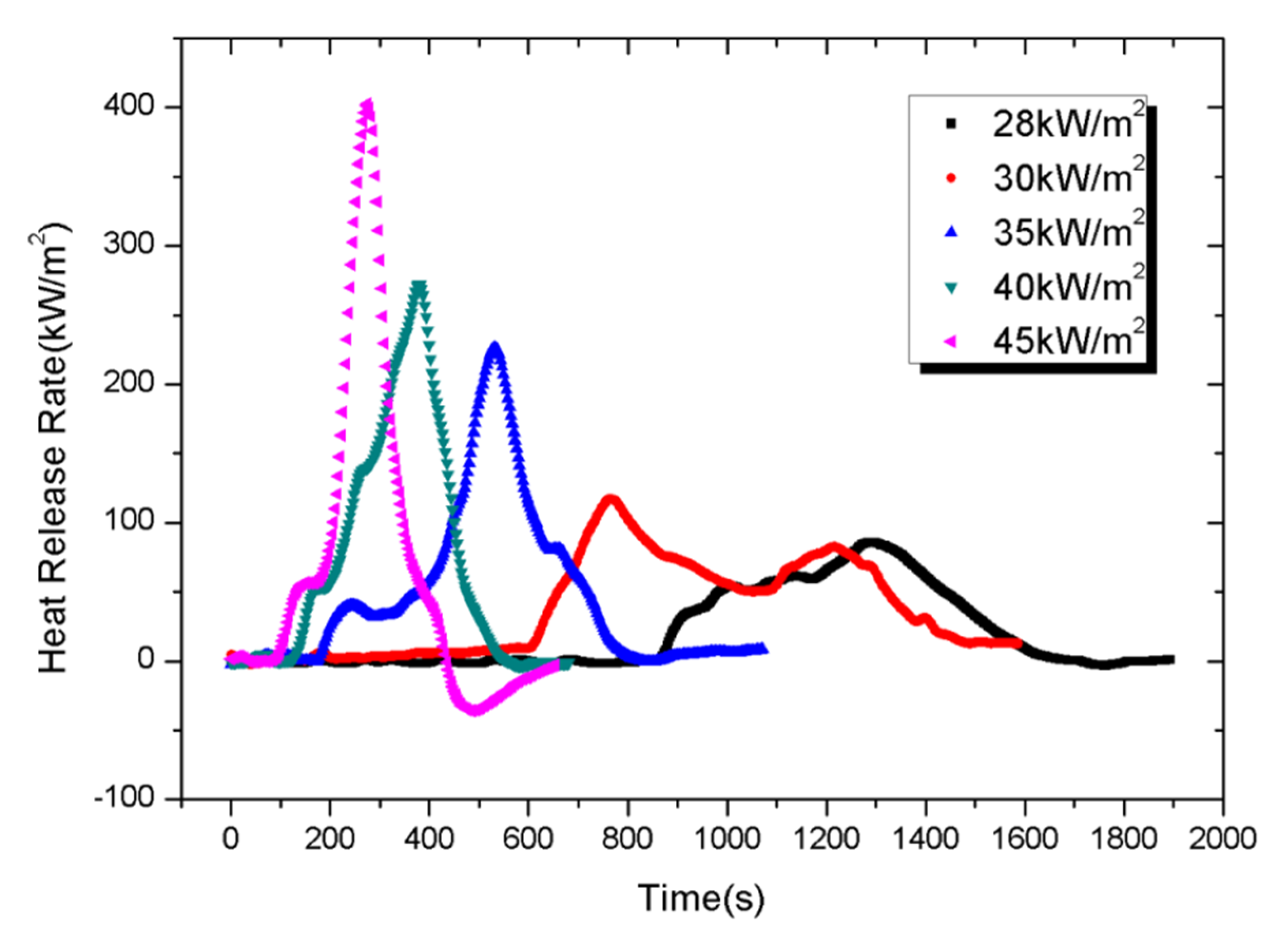
4.2. Fire Behaviour


4.3. Fire Hazards


| Values | x parameter | Total Heat Release (THR) |
|---|---|---|
| 0.1–1.0 | Low risk to flashover | Very low risk to heat contribution |
| 1.0–10 | Intermediate risk to flashover | Low risk to heat contribution |
| 10–100 | High risk to flashover | Intermediate low risk to heat contribution |
| 100–1000 | - | High risk to heat contribution |
| Heat flux (kW/m2) | Derived data | |||
|---|---|---|---|---|
| TTI (s) | pk HRR (kW/m2) | x parameter (kW/m2s) | THR (MJ/m2) | |
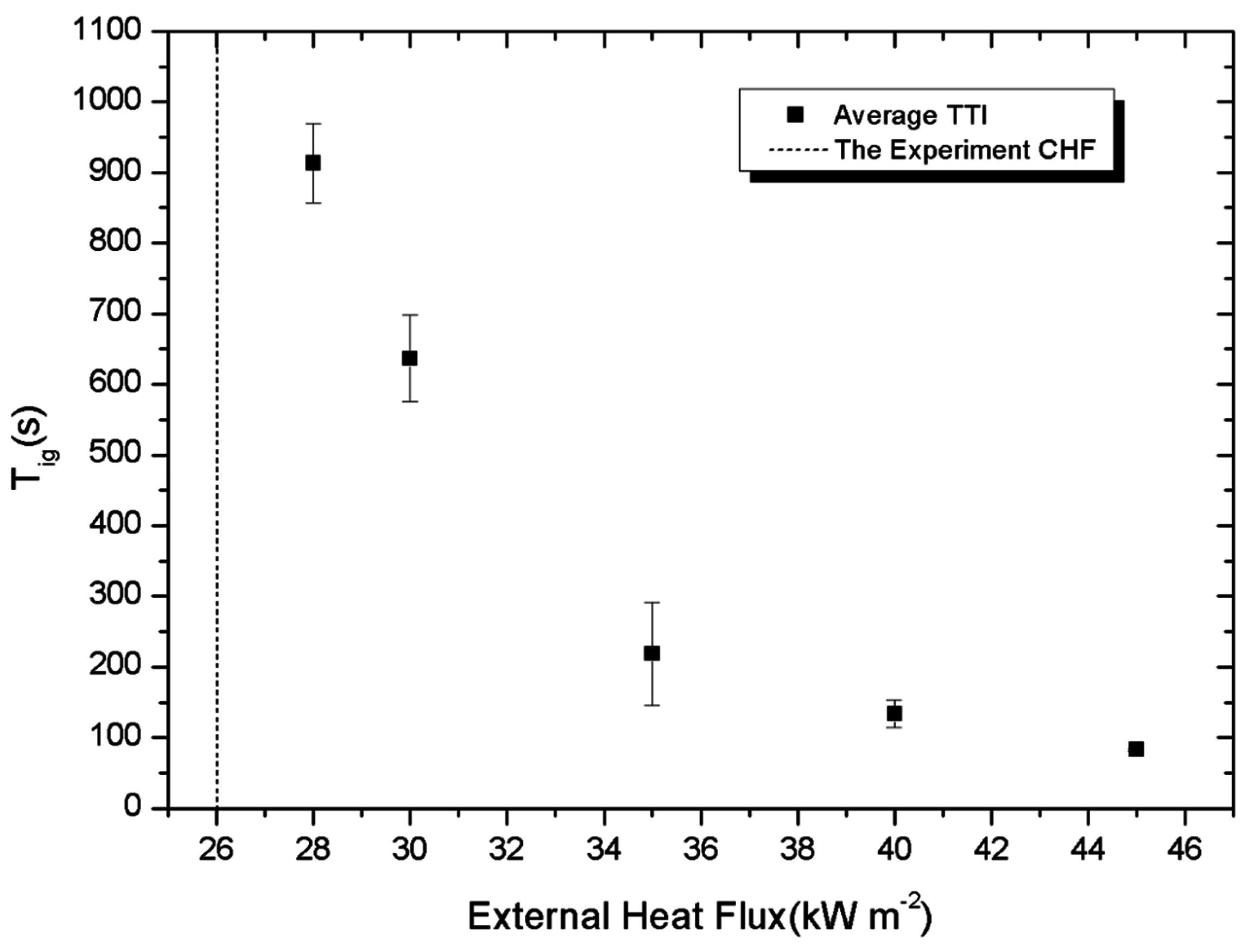
| 28 | 913 | 85 | 0.093 | 38.270 (Intermediate risk) |
| 30 | 636 | 116 | 0.182 (low risk) | 56.736 (Intermediate risk) |
| 35 | 218 | 226 | 1.037 (Intermediate risk) | 50.069 (Intermediate risk) |
| 40 | 133 | 272 | 2.045 (Intermediate risk) | 48.524 (Intermediate risk) |
| 45 | 83 | 402 | 4.843 (Intermediate risk) | 45.481 (Intermediate risk) |
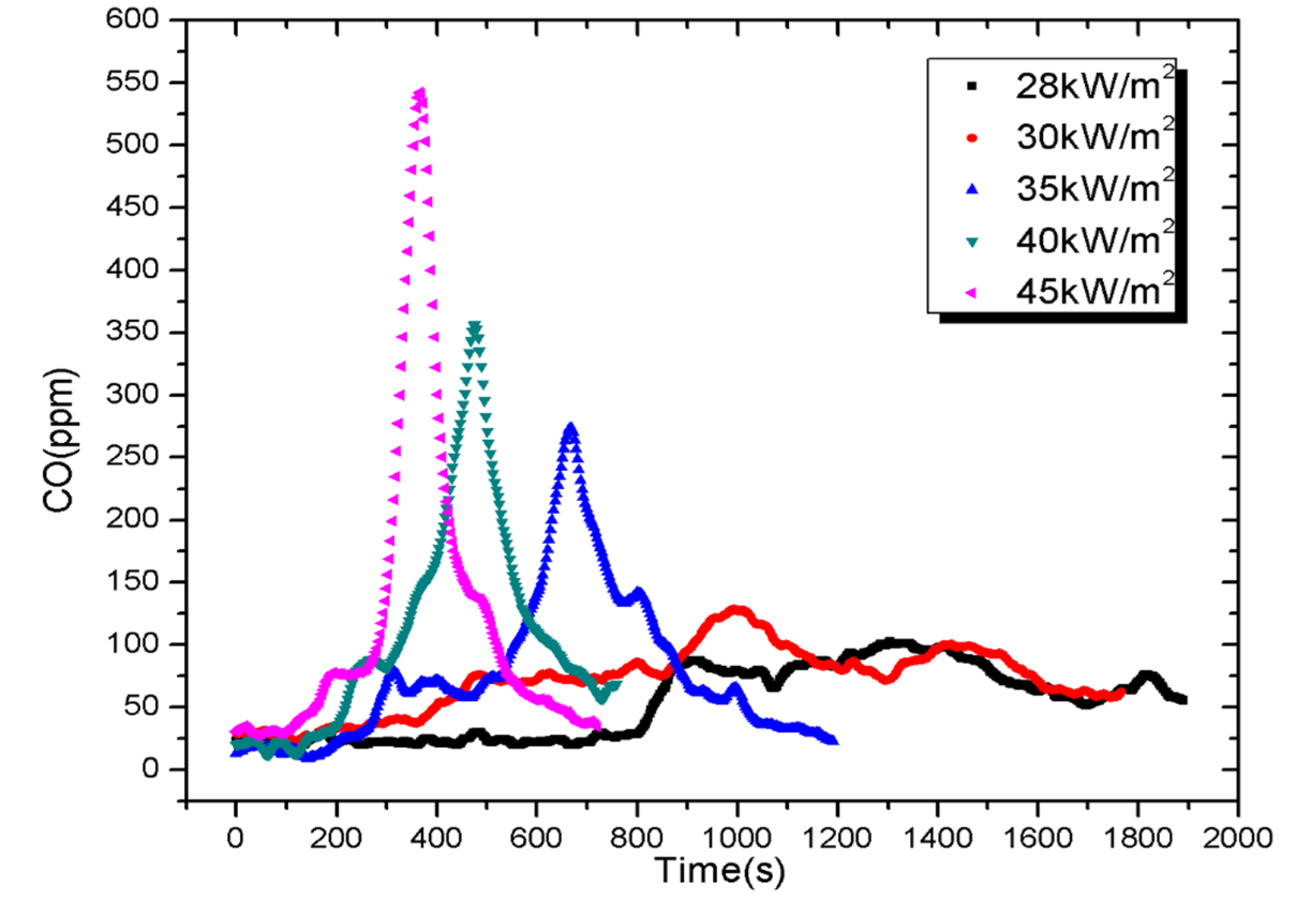
4.4. Toxicity of Gases


| Heat flux (kW/m2) | Peak CO (ppm) | FED = [CO]/5000 |
|---|---|---|
| 28 | 101 | 0.0202 |
| 30 | 128 | 0.0256 |
| 35 | 274 | 0.0548 |
| 40 | 356 | 0.0712 |
| 45 | 542 | 0.108 |
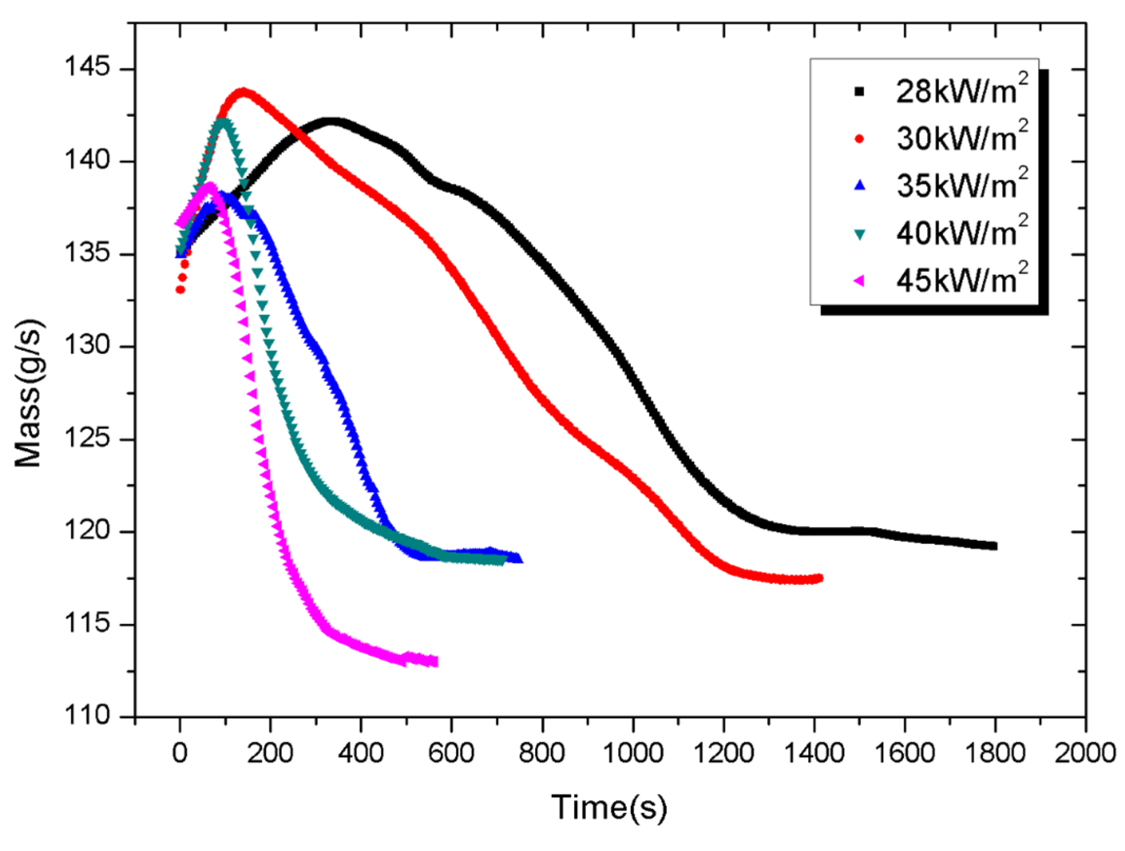
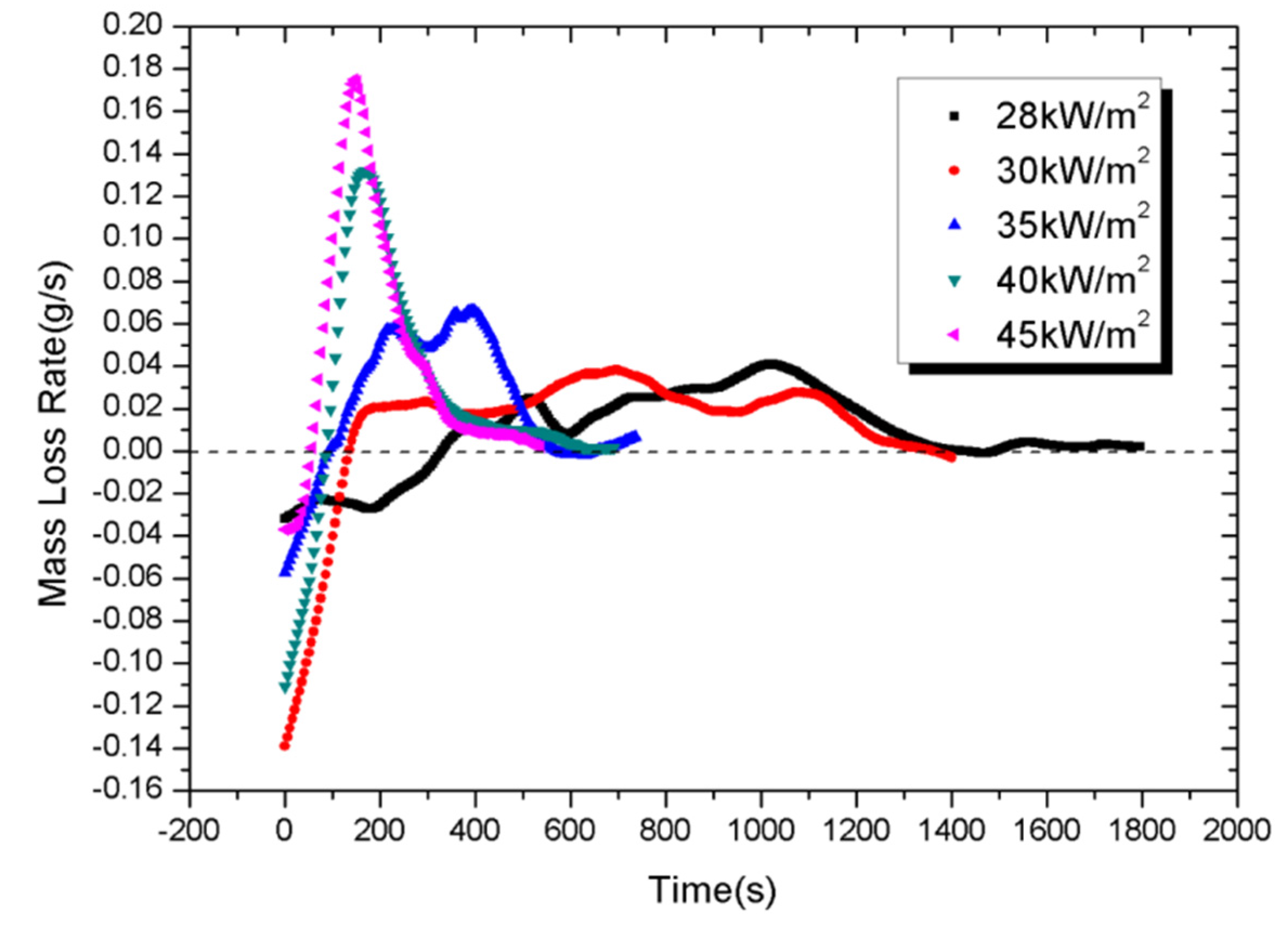
4.5. Mass Loss and Mass Loss Rate


5. Conclusions
Acknowledgments
Author Contributions
Conflicts of Interest
Nomenclature
| tig | ignition delay, s |
| ρ | density, kg/m3 |
| Cp | thermal capacity, kJ/(g K) |
| d | thickness of samples, m |
| T∞ | ambient temperature, K |
external heat flux, kW/m2 | |
| λ | thermal conductivity, kW/(mK) |
| [CO] | carbon monoxide concentration, ppm |
| [CO2] | carbon dioxide concentration, ppm |
| Tig | ignition temperature, K |
References
- Jelle, B.P.; Breivik, C.; Røkenes, H.D. Building integrated photovoltaic products: A state-of-the-art review and future research opportunities. Sol. Energy Mater. Sol. Cells 2012, 100, 69–96. [Google Scholar] [CrossRef]
- Wohlgemuth, J.H.; Kurtz, S.R. How can we make PV modules safer. In Proceeding of the 2012 38th IEEE on Photovoltaic Specialists Conference (PVSC), Austin, TX, USA, 3–8 June 2012; pp. 003162–003165.
- Bower, W. National electrical code changes in 2014 for photovoltaics: Processes, critical industry consensus topics and impacts. In Proceeding of the 2014 IEEE 40th on Photovoltaic Specialist Conference (PVSC), Denver, CO, USA, 8–13 June 2014; pp. 3352–3355.
- International Electrotechnical Commission. Photovoltaic (PV) Module Safety Qualification-Part 2: Requirements for Testing; IEC 61730-2:2004; International Electrotechnical Commission: Geneva, Switzerland, 2004. [Google Scholar]
- Underwriters Laboratories Inc. Flat-Plate Photovoltaic Modules and Panels; UL 1703; Underwriters Laboratories Inc.: Northbook, IL, USA, 2004. [Google Scholar]
- Underwriters Laboratories Inc. Fire Test of Roof Deck Constructions; UL 1256; Underwriters Laboratories Inc.: Northbrook, IL, USA, 2002. [Google Scholar]
- Cancelliere, P. PV electrical plants fire risk assessment and mitigation according to the Italian national fire services guidelines. Fire Mater. 2014. [Google Scholar] [CrossRef]
- National Fire Protection Association. National Electrical Code; NFPA70; National Fire Protection Association: Quincy, MA, USA, 2014. [Google Scholar]
- Tommasini, R.; Pons, E.; Palamara, F.; Turturici, C.; Colella, P. Risk of electrocution during fire suppression activities involving photovoltaic systems. Fire Saf. J. 2014, 67, 35–41. [Google Scholar] [CrossRef]
- Bonnet, J.; Bounor-Legaré, V.; Boisson, F.; Mélis, F.; Camino, G.; Cassagnau, P. Phosphorus based organic–inorganic hybrid materials prepared by reactive processing for EVA fire retardancy. Polym. Degrad. Stab. 2012, 97, 513–522. [Google Scholar] [CrossRef]
- Ohuchi, T.; Ishikawa, N.; Kozawa, Y. Improvement of the fire-proofing and fire-resistance properties of PV modules for building’s exterior walls. In Proceeding of the 2000 Conference Record of the Twenty-Eighth IEEE on Photovoltaic Specialists Conference, Anchorage, AK, USA, 15–22 September 2010; pp. 1533–1538.
- Fthenakis, V.M.; Fuhrmann, M.; Heiser, J.; Wang, W. Experimental investigation of emissions and redistribution of elements in CdTe PV modules during fires. In Proceeding of the 19th European PV Solar Energy Conference, Paris, France, 7–11 June 2004.
- Mei, L.; Infield, D.G.; Gottschalg, R.; Loveday, D.L.; Davies, D.; Berry, M. Equilibrium thermal characteristics of a building integrated photovoltaic tiled roof. Sol. Energy 2009, 83, 1893–1901. [Google Scholar] [CrossRef]
- Murata, K.; Yagiura, T.; Takeda, K.; Tanaka, M.; Kiyama, S. New type of photovoltaic module integrated with roofing material (highly fire-resistant PV tile). Sol. Energy Mater. Sol. Cells 2003, 75, 647–653. [Google Scholar] [CrossRef]
- Chow, W.K.; Han, S.S. Studies on fire behaviour of video compact disc (VCD) materials with a cone calorimeter. Polym. Test. 2004, 23, 685–694. [Google Scholar] [CrossRef]
- Luche, J.; Mathis, E.; Rogaume, T.; Richard, F.; Guillaume, E. High-density polyethylene thermal degradation and gaseous compound evolution in a cone calorimeter. Fire Saf. J. 2012, 54, 24–35. [Google Scholar] [CrossRef]
- Bakhtiyari, S.; Taghi-Akbari, L.; Ashtiani, M.J. Evaluation of thermal fire hazard of 10 polymeric building materials and proposing a classification method based on cone calorimeter results. Fire Mater. 2015, 39, 1–13. [Google Scholar] [CrossRef]
- Babrauskas, V. Development of the cone calorimeter—A bench-scale heat release rate apparatus based on oxygen consumption. Fire Mater. 1984, 8, 81–95. [Google Scholar] [CrossRef]
- Beaulieu, P.A.; Dembsey, N.A. Effect of oxygen on flame heat flux in horizontal and vertical orientations. Fire Saf. J. 2008, 43, 410–428. [Google Scholar] [CrossRef]
- Ito, A.; Kashiwagi, T. Characterization of flame spread over PMMA using holographic interferometry sample orientation effects. Combust. Flame 1988, 71, 189–204. [Google Scholar] [CrossRef]
- Ayani, M.B.; Esfahani, J.A.; Mehrabian, R. Downward flame spread over PMMA sheets in quiescent air: Experimental and theoretical studies. Fire saf. J. 2006, 41, 164–169. [Google Scholar] [CrossRef]
- Babrauskas, V. Speciman heat fluxes for bench-scale heat release rate testing. Fire Mater. 1995, 19, 243–252. [Google Scholar] [CrossRef]
- Quang, D.Q.; Luche, J.; Richard, F.; Rogaume, T.; Bourhy-Weber, C.; Ruban, S. Determination of characteristic parameters for the thermal decomposition of epoxy resin/carbon fibre composites in cone calorimeter. Int. J. Hydrog. Energy 2013, 38, 8167–8178. [Google Scholar] [CrossRef]
- Drysdale, D. An introduction to Fire Dynamics; John Wiley & Sons: Hoboken, NJ, USA, 2011. [Google Scholar]
- Patel, P.; Hull, T.R.; Stec, A.A.; Lyon, R.E. Influence of physical properties on polymer flammability in the cone calorimeter. Polym. Adv. Technol. 2011, 22, 1100–1107. [Google Scholar] [CrossRef]
- Janssens, M.A.R.C. A thermal model for piloted ignition of wood including variable thermophysical properties. In Fire Safety Science: Proceedings of the Third International Symposium; Taylor & Francis: New York, NY, USA, 1991; pp. 167–176. [Google Scholar]
- International Organization for Standardization. Reaction-to-Fire Tests—Heat Release, Smoke Production and Mass Loss Rate—Part 1: Heat Release Rate (Cone Calorimeter Method); ISO 5660-1:2002; International Organization for Standardization: Geneva, Switzerland, 2002. [Google Scholar]
- Petrella, R.V. The assessment of full-scale fire hazards from cone calorimeter data. J. Fire Sci. 1994, 12, 14–43. [Google Scholar] [CrossRef]
- Chow, W.K. Fire hazard assessment on polyurethane sandwich panels for temporary accommodation units. Polym. Test. 2004, 23, 973–977. [Google Scholar] [CrossRef]
- Bakhtiyari, S.; Taghiakbari, L.; Barikani, M. Fire behavior of rigid PUR foam and metal faced PUR sandwich panels and fire hazard assessment. Iran. J. Polym. Sci. Technol. 2009, 22, 183–195. [Google Scholar]
- Leonard, J.E.; Bowditch, P.A.; Dowling, V.P. Development of a controlled-atmosphere cone calorimeter. Fire Mater. 2000, 24, 143–150. [Google Scholar] [CrossRef]
© 2015 by the authors; licensee MDPI, Basel, Switzerland. This article is an open access article distributed under the terms and conditions of the Creative Commons Attribution license (http://creativecommons.org/licenses/by/4.0/).
Share and Cite
Yang, H.-Y.; Zhou, X.-D.; Yang, L.-Z.; Zhang, T.-L. Experimental Studies on the Flammability and Fire Hazards of Photovoltaic Modules. Materials 2015, 8, 4210-4225. https://doi.org/10.3390/ma8074210
Yang H-Y, Zhou X-D, Yang L-Z, Zhang T-L. Experimental Studies on the Flammability and Fire Hazards of Photovoltaic Modules. Materials. 2015; 8(7):4210-4225. https://doi.org/10.3390/ma8074210
Chicago/Turabian StyleYang, Hong-Yun, Xiao-Dong Zhou, Li-Zhong Yang, and Tao-Lin Zhang. 2015. "Experimental Studies on the Flammability and Fire Hazards of Photovoltaic Modules" Materials 8, no. 7: 4210-4225. https://doi.org/10.3390/ma8074210