
Experiment Analysis on Crack Resistance in Negative Moment Zone of Steel–Concrete Composite Continuous Girder Improved by Interfacial Slip

Abstract
:1. Introduction
2. Preparation of Experimental Scheme
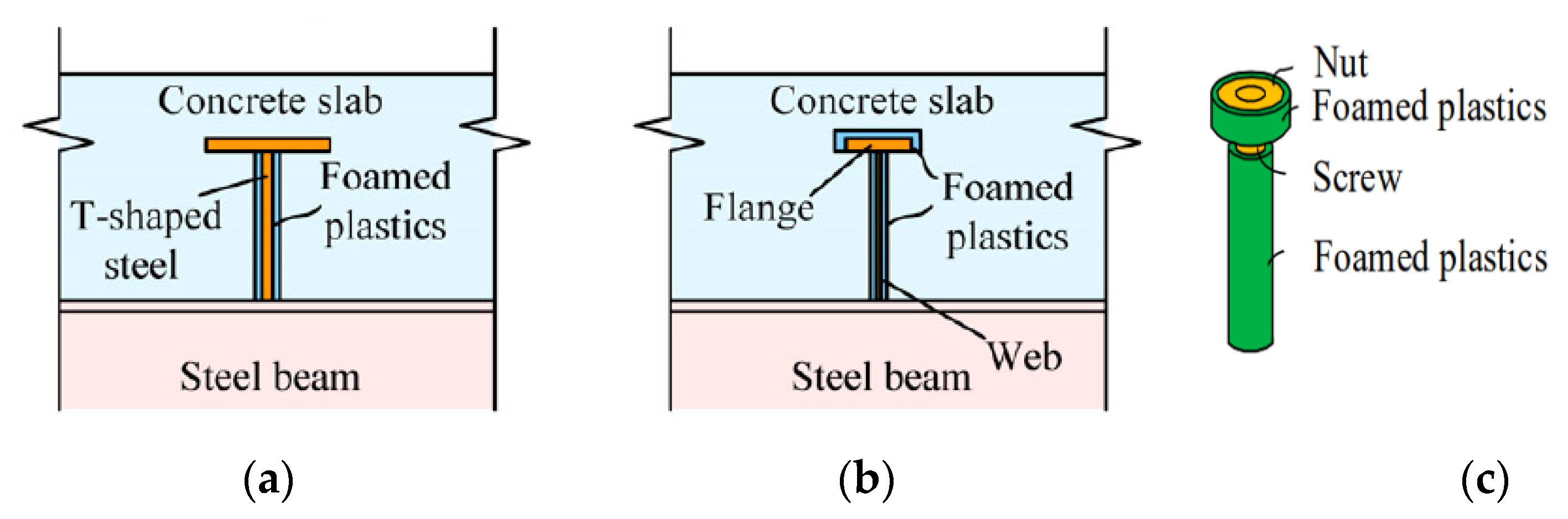
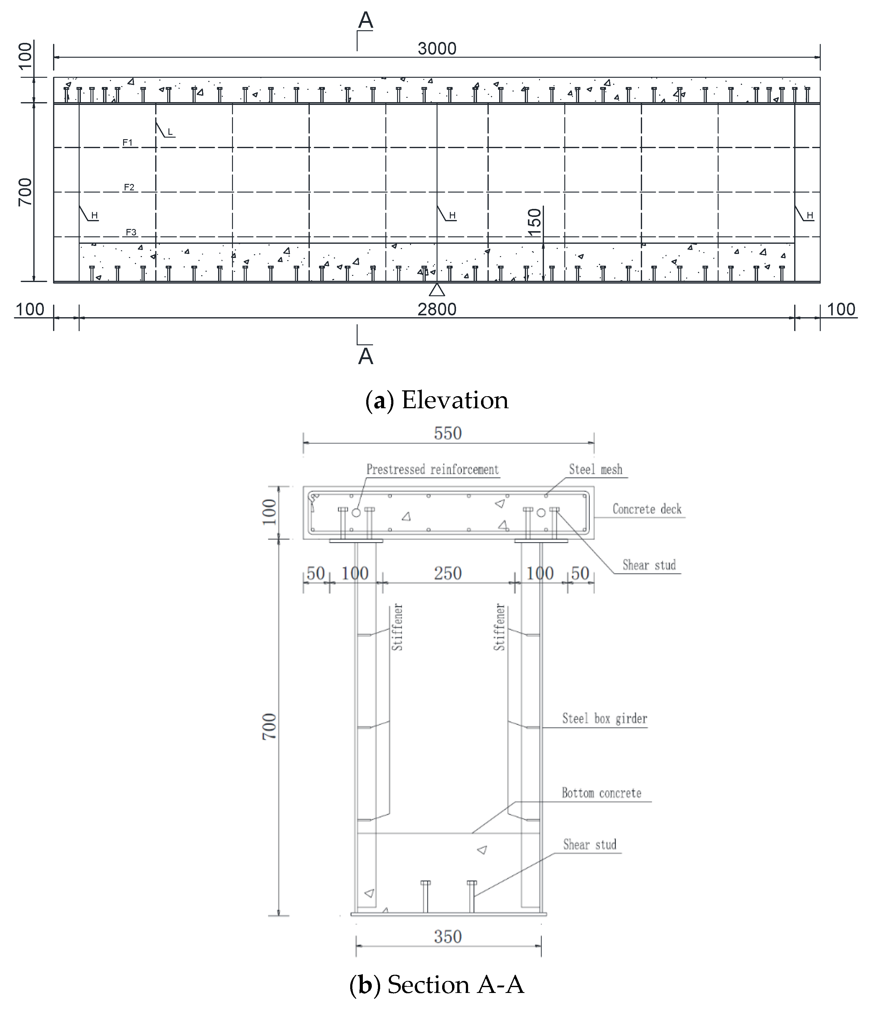
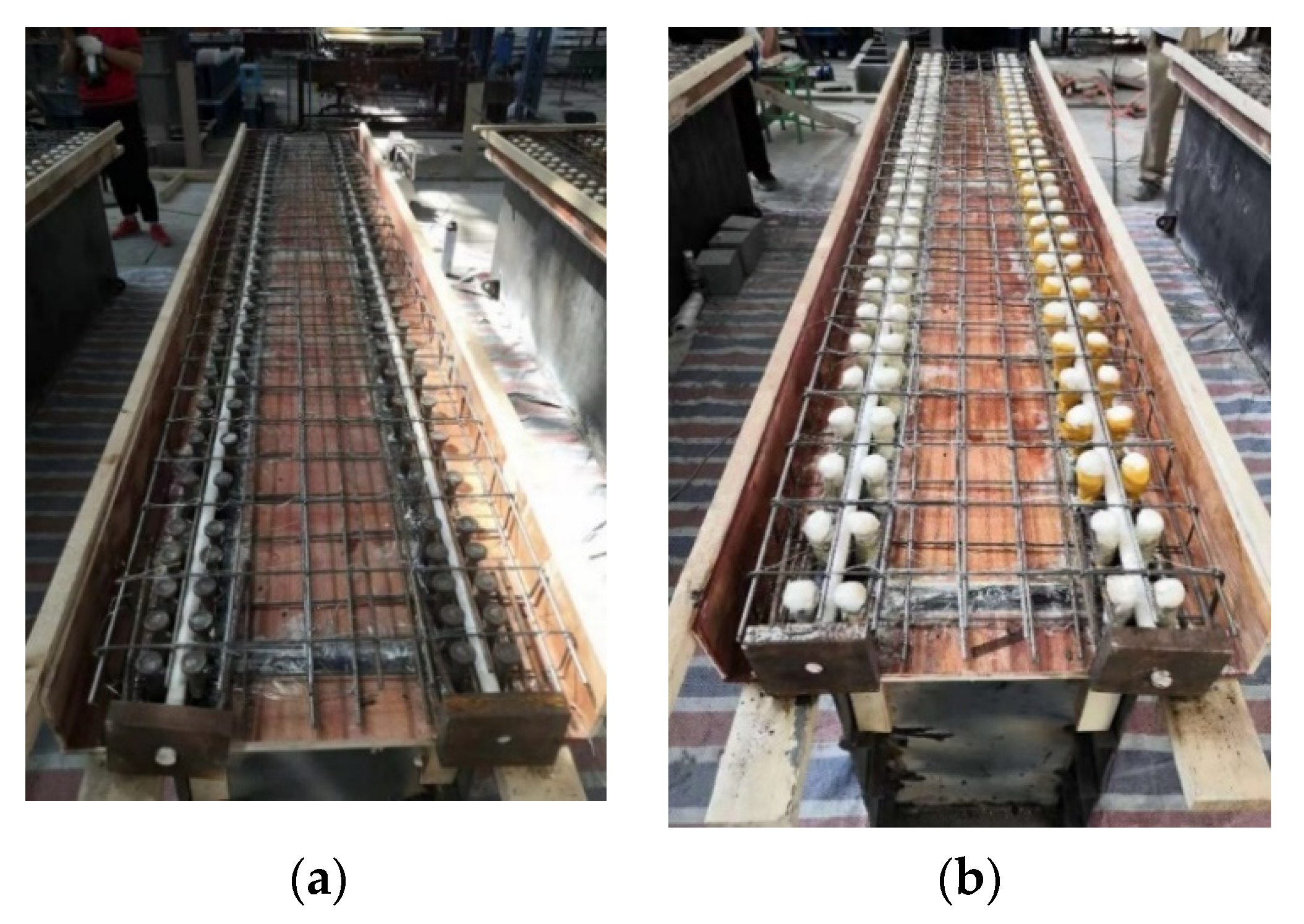
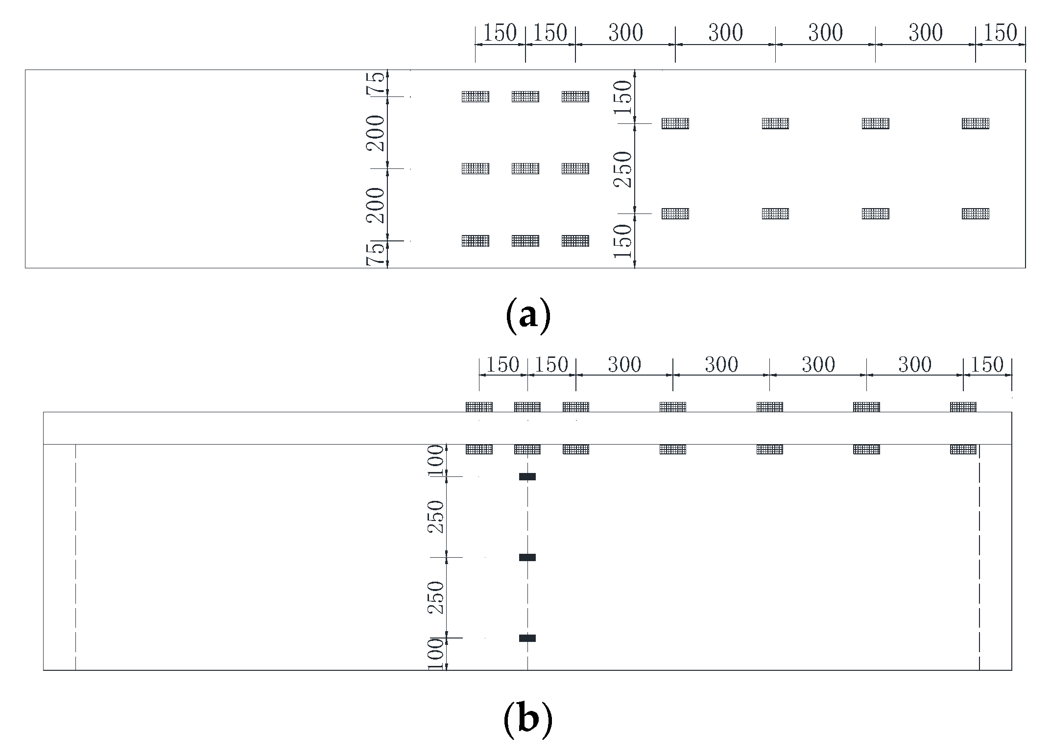
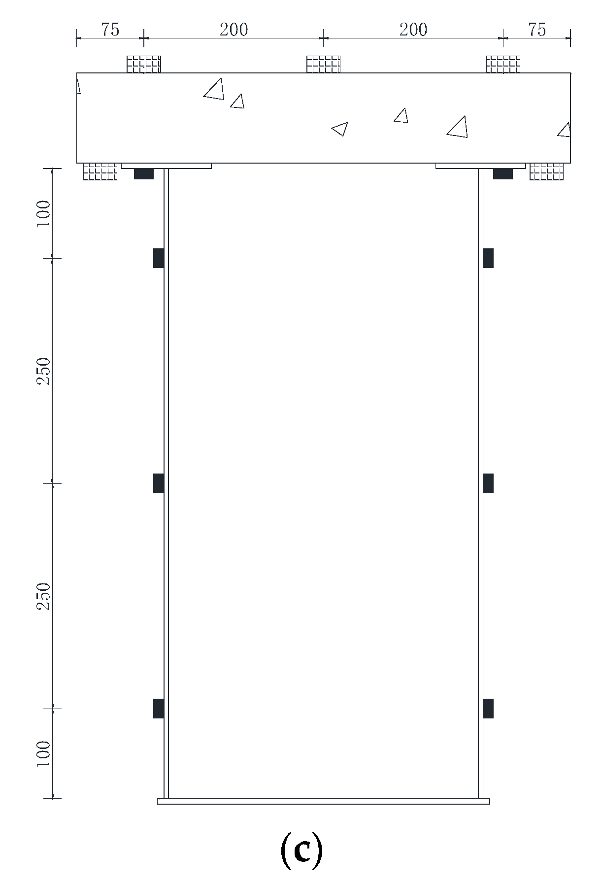
2.1. Specimen Design
2.2. Material Performance
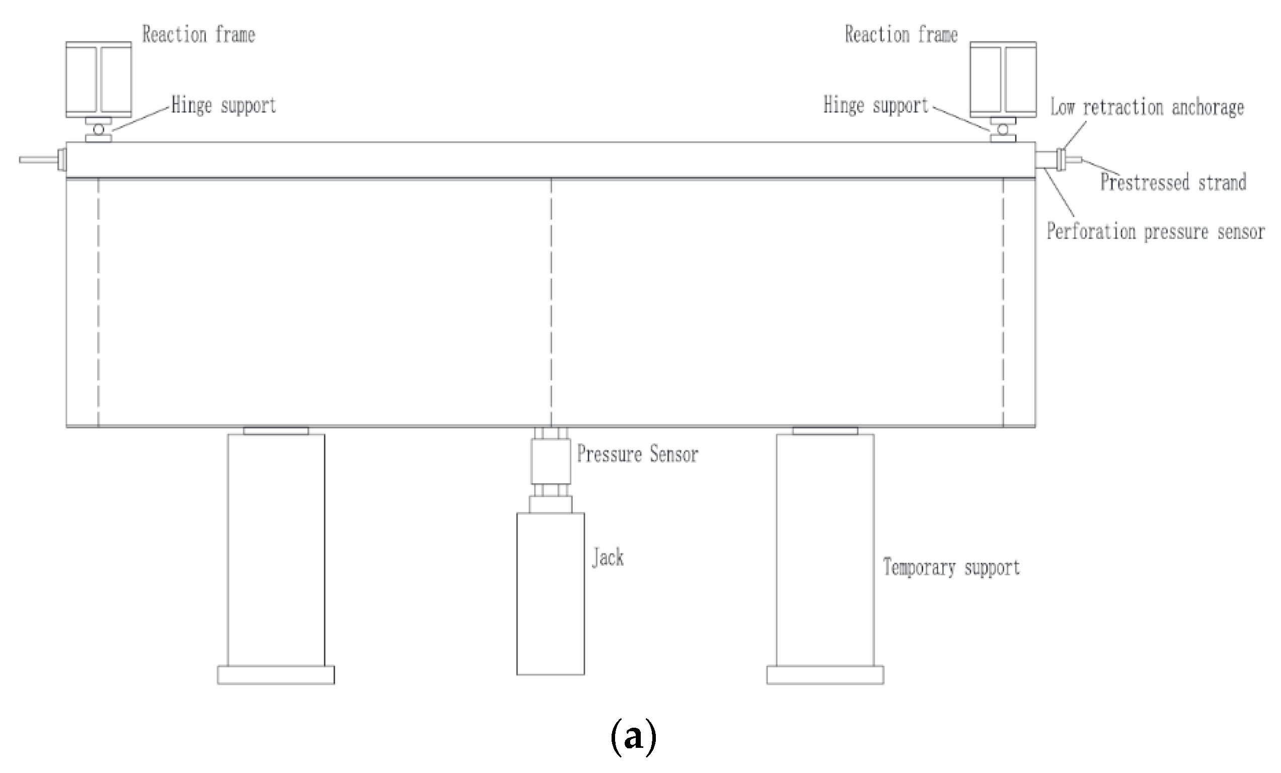
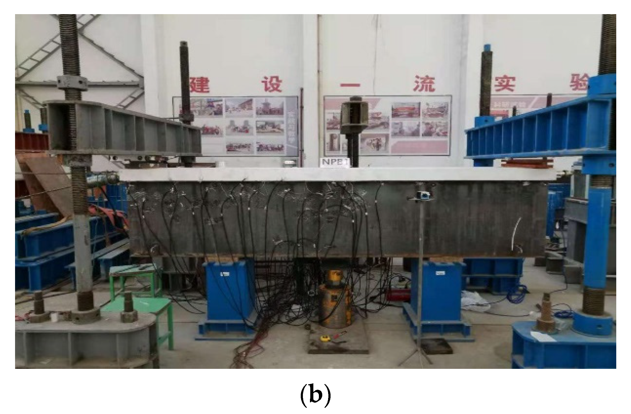
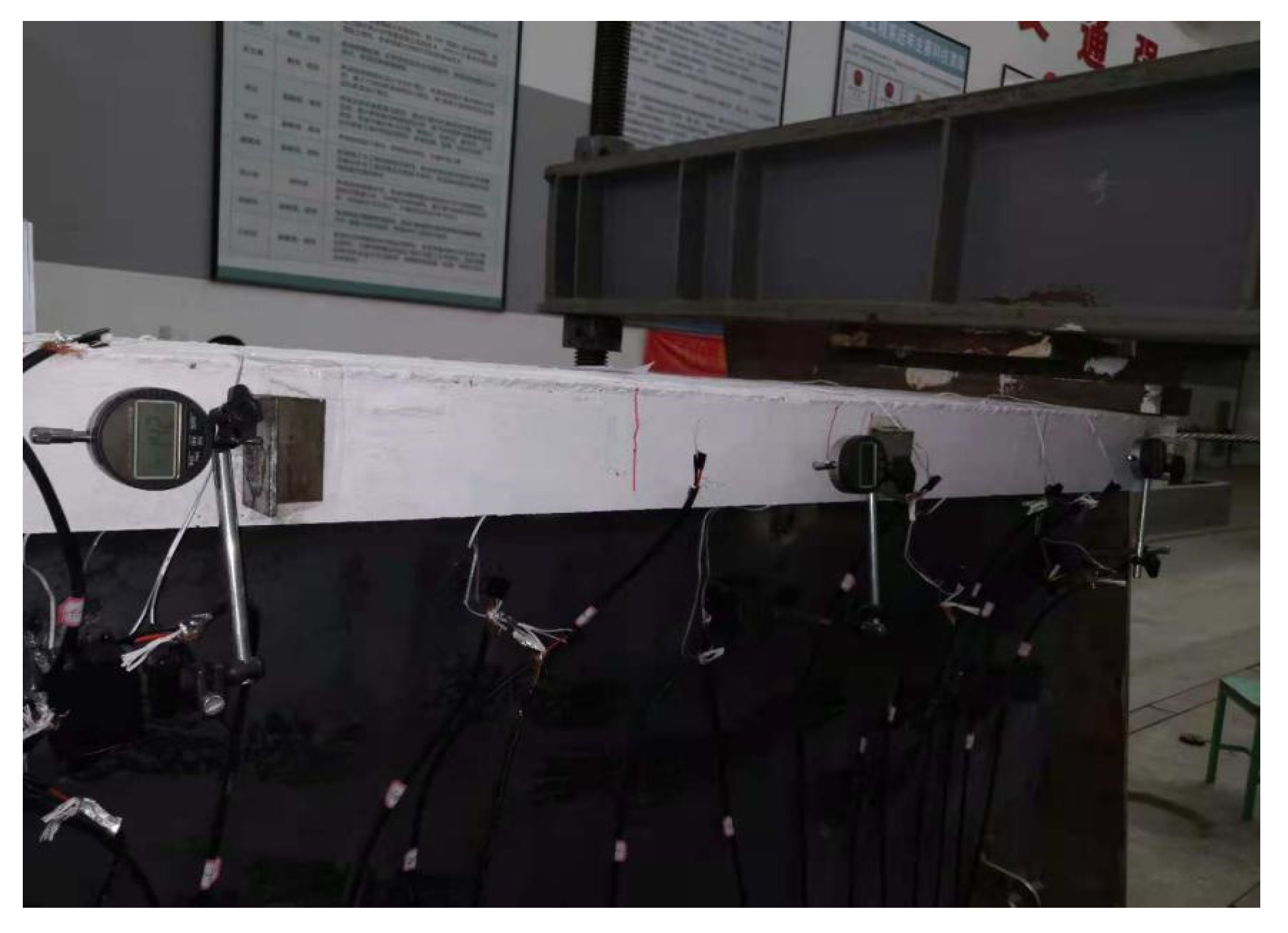
2.3. Loading Conditions
- (1)
- Tensioning prestress bars of the upper concrete slab
- (2)
- Loading upward in the mid-span section of test beam
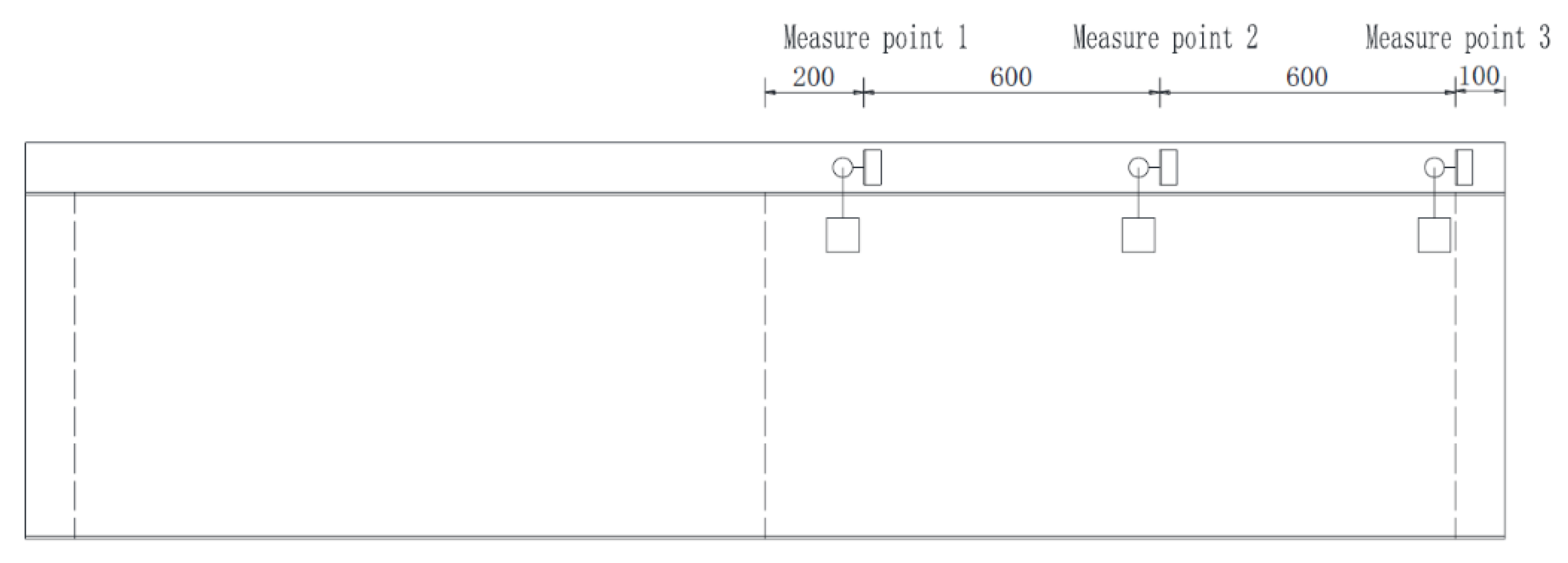
2.4. Layout of Measuring Points
3. Analysis of Crack Resistance by Experimental Results
- (1)
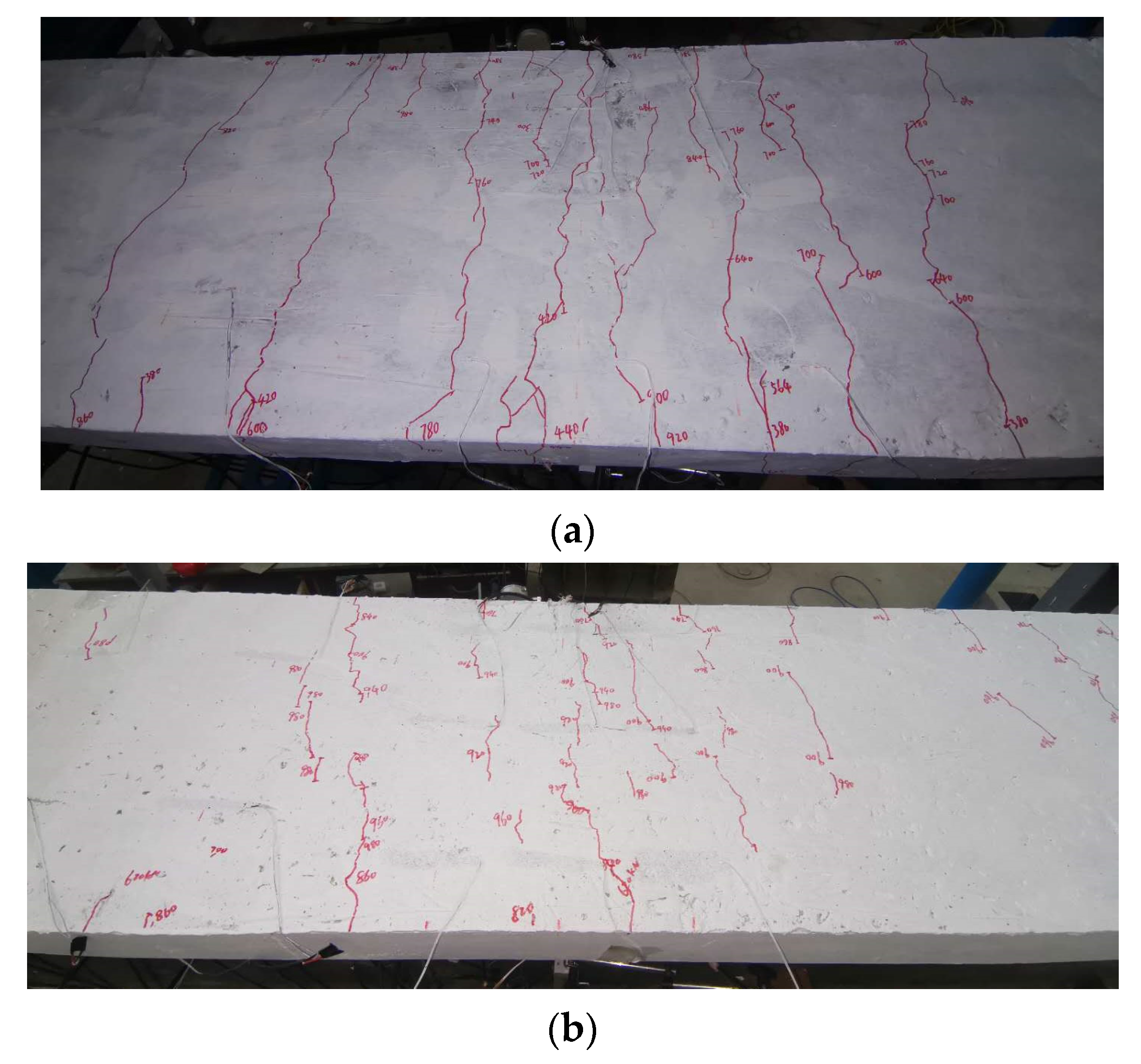
- Specimen SRB
- (2)
- Specimen SPB
- (3)
- Comparison of crack property on two experimental beams
- The initial cracking load of specimen SPB was 107% higher than that of specimen SRB, indicating that the interface slip effect between steel and concrete of specimen SPB was more pronounced, due to the use of URSP connectors, which improves crack resistance.
- SPB specimens had a slower fracture follow-up rate than SRB specimens. When the loading value of specimen SRB reached 490 kN, the first main fracture ran through the concrete slab, and a total of 8 main fractures were generated, with a maximum fracture width of 0.2 mm. However, as a result of loading, specimen SPB did not show any obvious main cracks and had a maximum crack width of 0.02 mm. This indicates that the interface slip effect can slow down the crack development speed of concrete slab and effectively reduce the crack width under the same loading conditions.
- In terms of fracture distribution, specimen SPB had a wider fracture distribution range. It indicates that the tensile stress distribution of specimen SPB is more uniform than that of specimen SRB.
4. Comparative Analysis of Stiffness, Interfacial Slip, Prestress Efficiency, and Other Test Indicators of Two Experimental Specimens
- (1)
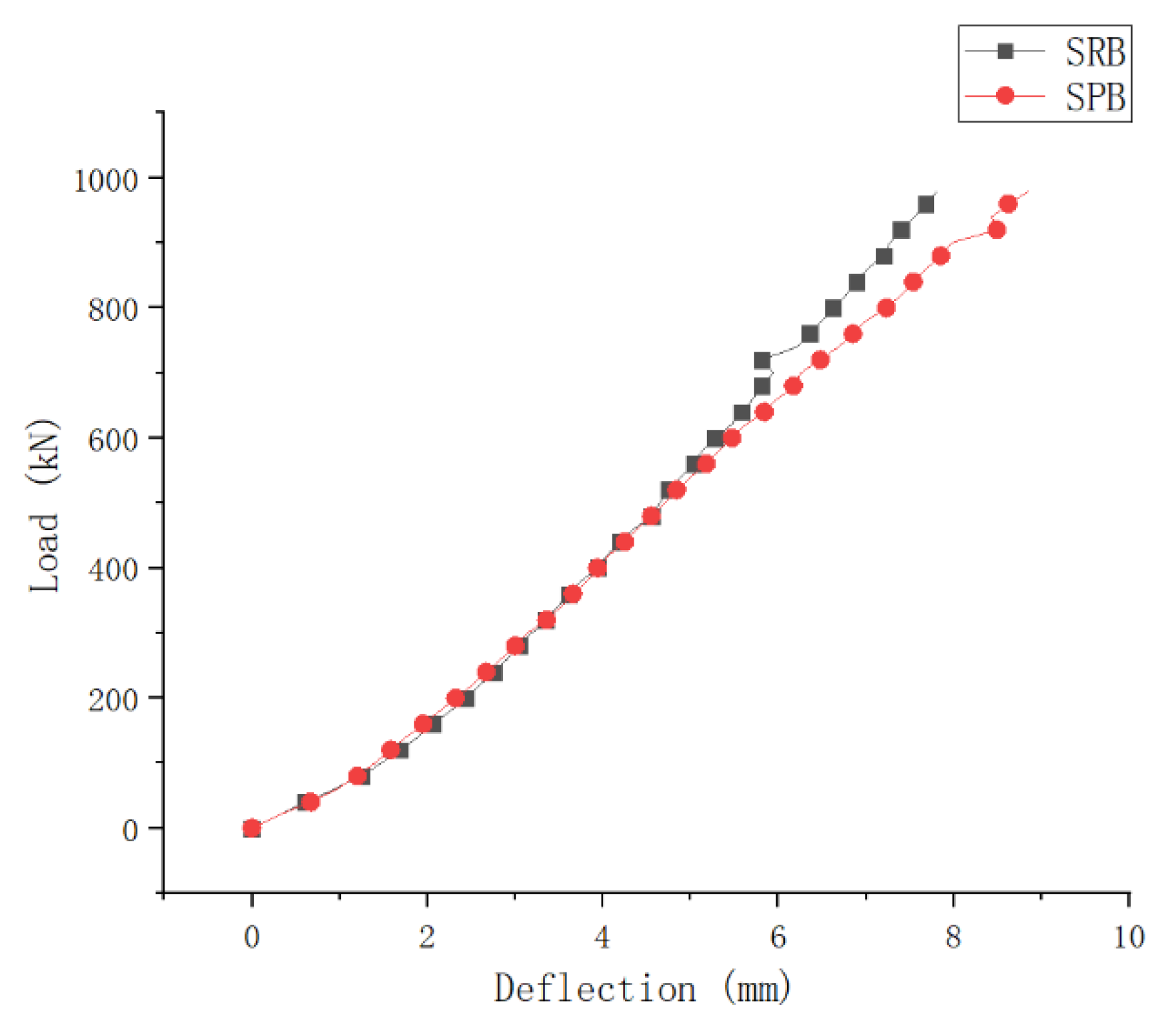
- Comparative analysis of stiffness
- (2)
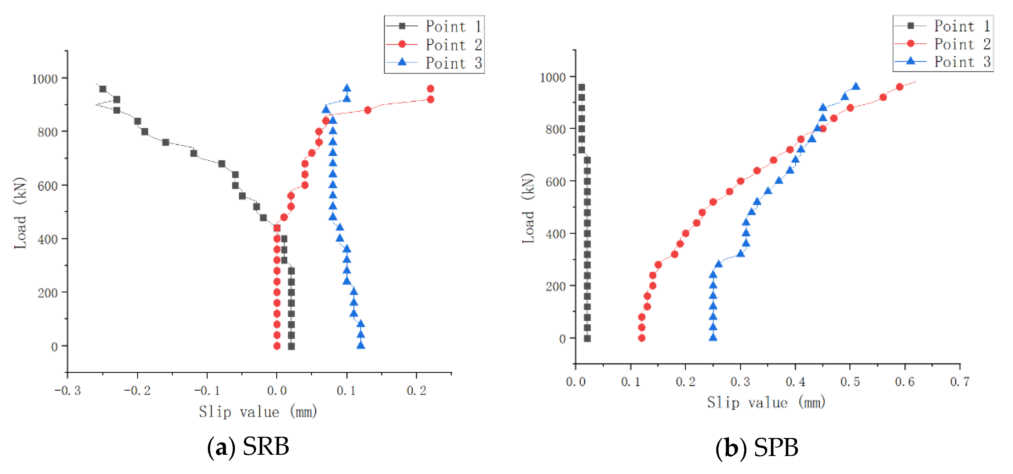
- Comparative analysis of interface slip
- (3)
- Comparative analysis of prestress efficiency
- (4)
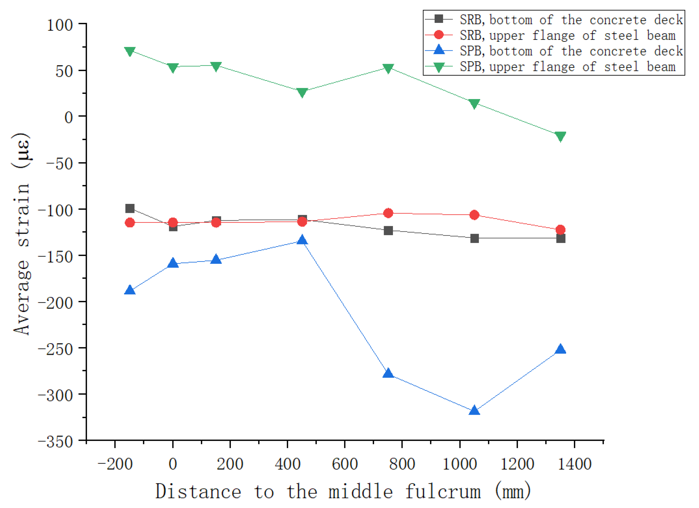
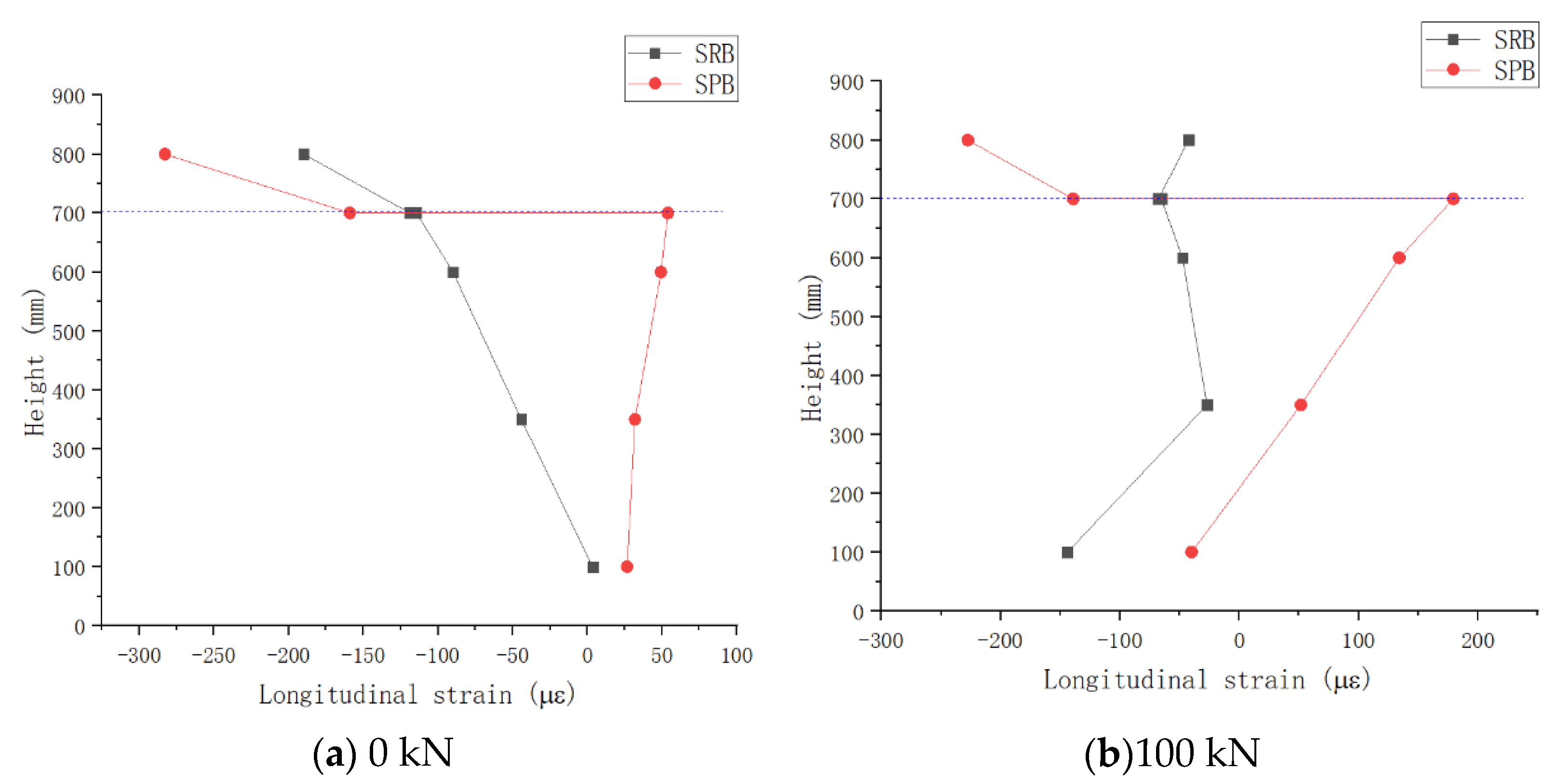
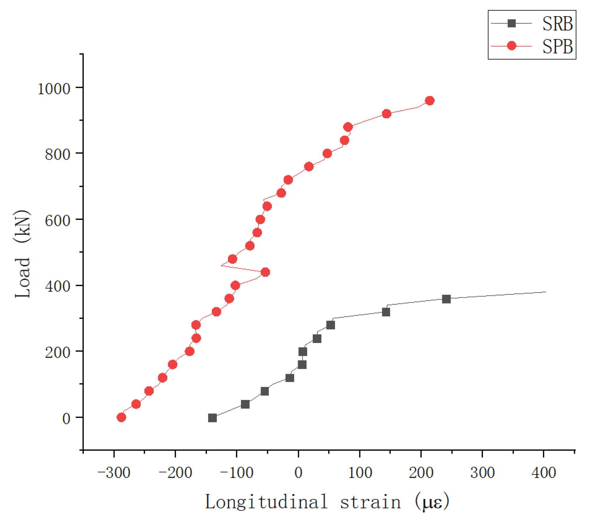
- Comparative analysis of longitudinal strain distribution at the mid-span section
- In each loading stage, the longitudinal strains of the bottom surface of the concrete slab and the upper flange plate of the steel portion of specimen SRB were basically the same, indicating that the concrete slab and the steel portion formed a combined section to work together. However, the longitudinal strain of concrete slab and steel portion of SPB was much different from that of SRB, and both had specific strain distribution characteristics, respectively. This shows that two portions in the negative bending moment region of specimen SPB formed an ideal laminated beam, and the steel structure and concrete slab bore the load, respectively.
- Figure 13a shows that specimen SRB concrete slab had a smaller compressive strain under prestressing alone than specimen SPB, while the compressive strain on the top surface of steel portion of specimen SRB was significantly larger than that of specimen SPB, indicating that specimen SRB exhibited a significantly greater compressive strain on the top surface of steel than specimen SPB. However, SPB showed large longitudinal strain gaps between the concrete slab and steel portion, and there were no compressive strains in most sections of the steel portion. Through the new type of connectors, the interface slip effect prevented the prestress exerted on the concrete slab from transferring to the steel portion, and the concrete slab itself bore most of the prestress, thus improving the prestress efficiency of composite girder.
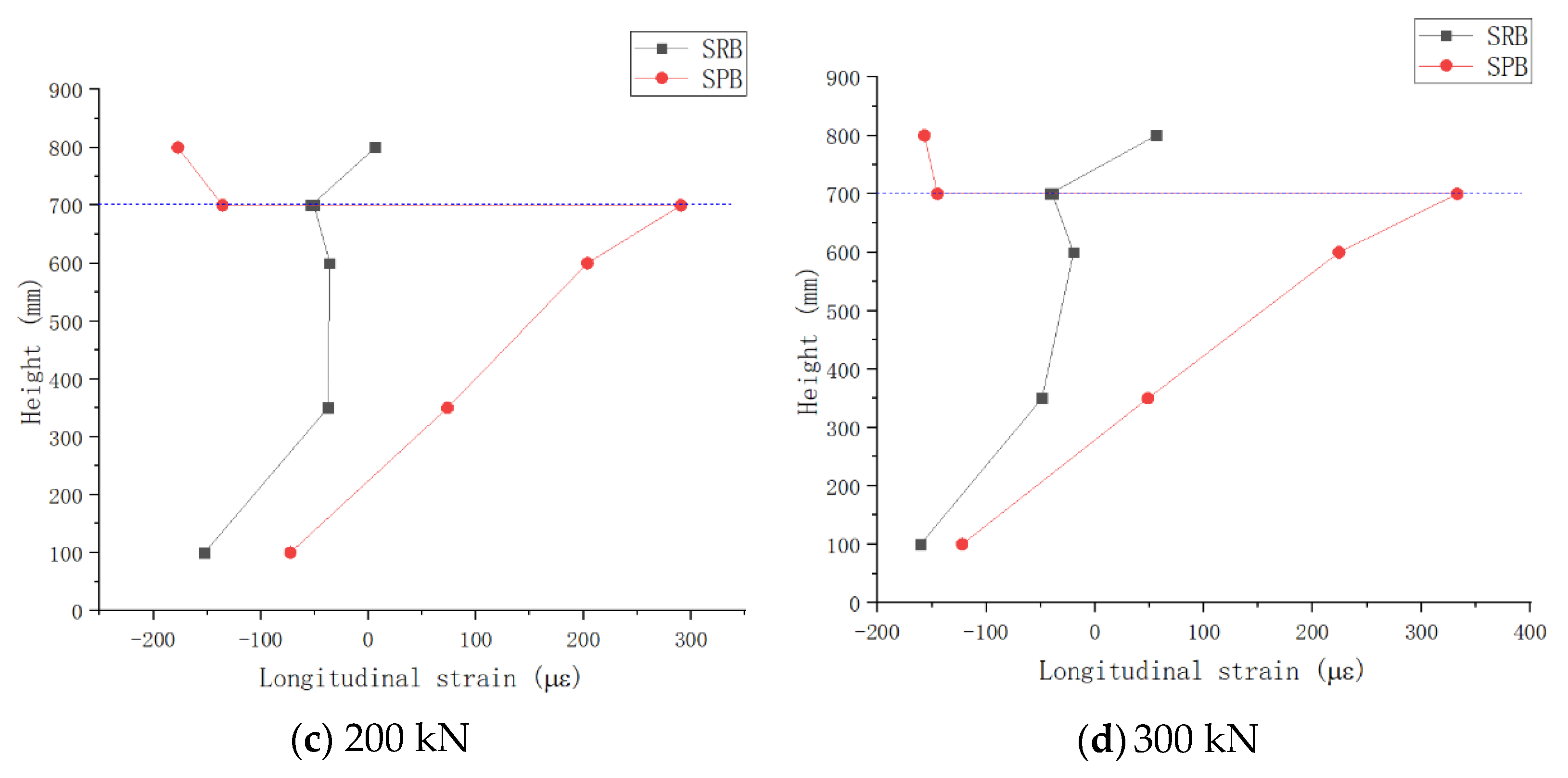
- In the subsequent loading stages, the compressive strain of the concrete slab in specimen SRB was smaller than that of concrete slab in specimen SPB, and the tensile strain of the steel portion in specimen SRB was smaller than that in the specimen SPB steel portion. The above facts show that most of the negative bending moment is borne by the steel beam due to the interface slip effect, thus reducing the tensile stress borne by the concrete slab.
- It is obvious that the increase in tensile strain on the top surface of concrete slabs in specimen SPB was smaller than that in specimen SRB as applied load increases, so the interface slip effect caused specimen SPB have a better crack resistance.
- (5)
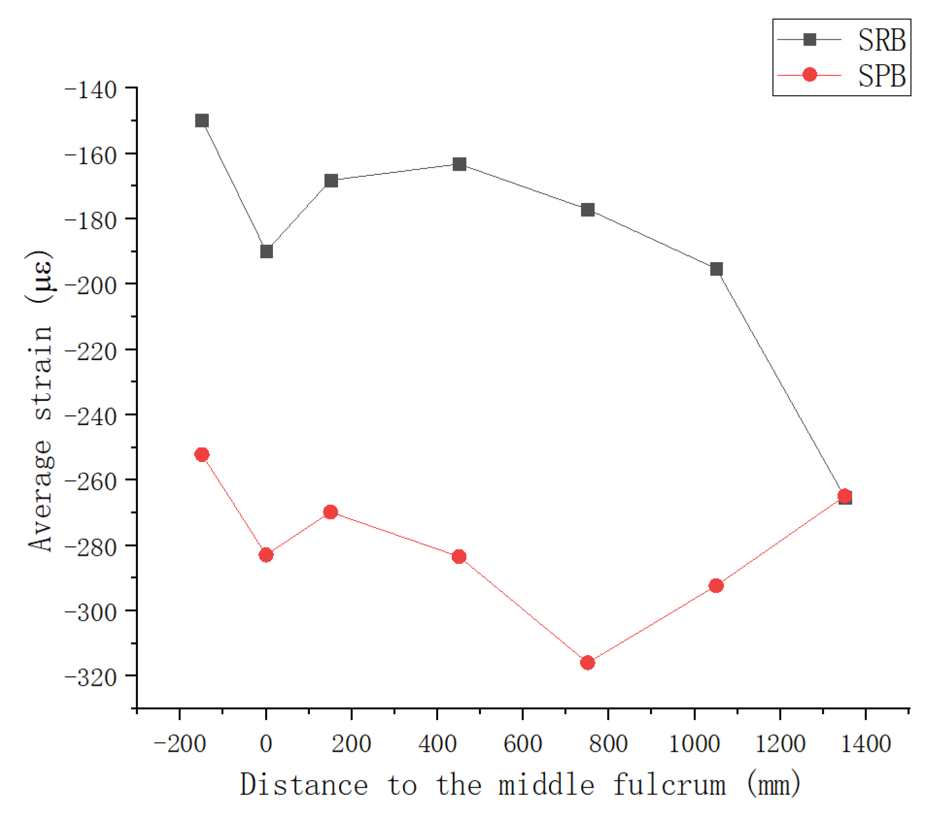
- Analysis on strain on top surface of concrete slab at mid-span section
- (6)
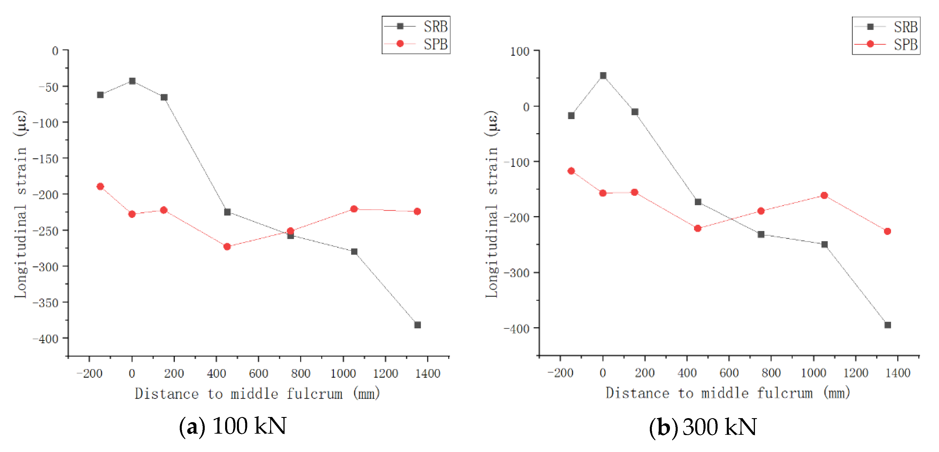
- Comparative analysis of the longitudinal distribution of strain on the top surface of concrete slab
5. Conclusions
- (1)
- The model tests show that the crack resistance of continuous composite beams in the negative moment region can be improved significantly by releasing the interface slip. The cracking load of composite structure rises by 107% when the continuous composite structure uses the uplift-restricted and slip-permitted connectors in the negative moment zone, due to releasing its interface slip. Moreover, the interface slip can make the tensile stress distribution more uniform on the concrete slab within the negative bending moment region and avoid the concentration of tensile stress in the mediate support, resulting in a wider distribution of cracks in the bridge deck within the negative bending moment region and a slower development rate of cracks.
- (2)
- Compared with the composite beam with conventional shear studs, the composite beam with Uplift-Restricted and Slip-Permitted shear connectors has a higher pre-stress application efficiency, due to an important fact the new connector could release the interface slip. As the interface slip is released, the applied prestress can be effectively retained in the concrete slab, preventing the prestress from being transferred to the steel structure through the shear connectors.
- (3)
- Another working mechanism in which the releasing interface slip improves the crack resistance of the structure is that, during the loading stage, specimen SPB behaves with lower values of both tensile strain and tensile strain growth curvature than specimen SRB, and the tensile strain distribution in the concrete slab of specimen SPB is more uniform along the longitudinal direction. This indicates that releasing the interface slip can effectively slow down the increase of the tensile strain of the concrete slab during the loading process after cracking.
- (4)
- Despite the application of uplift-restricted and slip-permitted connectors in the hogging moment zone, the structural stiffness of the SPB beam was not significantly different from that of the continuous composite structure with traditional stud connectors, indicating that, in the negative moment zone of the continuous composite box girder, the releasing interface slip had no significant effect on structural stiffness.
Author Contributions
Funding
Institutional Review Board Statement
Informed Consent Statement
Data Availability Statement
Conflicts of Interest
References
- Su, Q.-T.; Yang, G.-T.; Wu, C. Experimental investigation on inelastic behavior of composite box girder under negative moment. Int. J. Steel Struct. 2012, 12, 71–84. [Google Scholar] [CrossRef]
- De Maio, U.; Greco, F.; Leonetti, L.; Blasi, P.N.; Pranno, A. A cohesive fracture model for predicting crack spacing and crack width in reinforced concrete structures. Eng. Fail. Anal. 2022, 139, 106452. [Google Scholar] [CrossRef]
- Fan, J.; Gou, S.; Ding, R.; Zhang, J.; Shi, Z. Experimental and analytical research on the flexural behaviour of steel–ECC composite beams under negative bending moments. Eng. Struct. 2020, 210, 110309. [Google Scholar] [CrossRef]
- Qi, J.; Cheng, Z.; Wang, J.; Tang, Y. Flexural behavior of steel-UHPFRC composite beams under negative moment. Structures 2020, 24, 640–649. [Google Scholar] [CrossRef]
- Zhang, Y.; Cai, S.; Zhu, Y.; Fan, L.; Shao, X. Flexural responses of steel-UHPC composite beams under hogging moment. Eng. Struct. 2020, 206, 110134. [Google Scholar] [CrossRef]
- Fan, J.; Nie, X.; Li, Q.; Li, Q. Long-Term Behavior of Composite Beams under Positive and Negative Bending. II: Analytical Study. J. Struct. Eng. 2010, 136, 858–865. [Google Scholar] [CrossRef]
- Fan, J.; Nie, J.; Li, Q.; Wang, H. Long-Term Behavior of Composite Beams under Positive and Negative Bending. I: Experimental Study. J. Struct. Eng. 2010, 136, 849–857. [Google Scholar] [CrossRef]
- El-Zohairy, A.; Salim, H.; Saucier, A. Steel–Concrete Composite Beams Strengthened with Externally Post-Tensioned Tendons under Fatigue. J. Bridg. Eng. 2019, 24, 04019027. [Google Scholar] [CrossRef]
- Nie, J.-G.; Li, Y.-X.; Tao, M.-X.; Nie, X. Uplift-Restricted and Slip-Permitted T-Shape Connectors. J. Bridg. Eng. 2015, 20, 30–42. [Google Scholar] [CrossRef]
- Nie, J.; Wang, J.; Gou, S.; Zhu, Y.; Fan, J. Technological development and engineering applications of novel steel-concrete composite structures. Front. Struct. Civ. Eng. 2019, 13, 1–14. [Google Scholar] [CrossRef]
- He, J.; Liu, Y.; Chen, A.; Yoda, T. Experimental study on inelastic mechanical behaviour of composite girders under hogging moment. J. Constr. Steel Res. 2010, 66, 37–52. [Google Scholar] [CrossRef]
- Saari, W.K.; Hajjar, J.F.; Schultz, A.E.; Shield, C.K. Behavior of shear studs in steel frames with reinforced concrete infill walls. J. Constr. Steel Res. 2004, 60, 1453–1480. [Google Scholar] [CrossRef]
- Shim, C.-S.; Lee, P.-G.; Yoon, T.-Y. Static behavior of large stud shear connectors. Eng. Struct. 2004, 26, 1853–1860. [Google Scholar] [CrossRef]
- Lee, P.-G.; Shim, C.-S.; Chang, S.-P. Static and fatigue behavior of large stud shear connectors for steel–concrete composite bridges. J. Constr. Steel Res. 2005, 61, 1270–1285. [Google Scholar] [CrossRef]
- Tan, Y.; Zhu, B.; Yan, T.; Huang, B.; Wang, X.; Yang, W.; Huang, B. Experimental Study of the Mechanical Behavior of the Steel–Concrete Joints in a Composite Truss Bridge. Appl. Sci. 2019, 9, 854. [Google Scholar] [CrossRef]
- Nie, J.G.; Tao, M.X. Slab spatial composite effect in composite frame systems. I: Effective width for ultimate loading capacity. Eng. Struct. 2012, 38, 171–184. [Google Scholar] [CrossRef]
- Bursi, O.S.; Sun, F.-F.; Postal, S. Non-linear analysis of steel–concrete composite frames with full and partial shear connection subjected to seismic loads. J. Constr. Steel Res. 2005, 61, 67–92. [Google Scholar] [CrossRef]
- Wang, J.; Wang, W.; Lehman, D.; Roeder, C. Effects of different steel-concrete composite slabs on rigid steel beam-column connection under a column removal scenario. J. Constr. Steel Res. 2019, 153, 55–70. [Google Scholar] [CrossRef]
- Amadio, C.; Bedon, C.; Fasan, M. Numerical assessment of slab-interaction effects on the behaviour of steel-concrete composite joints. J. Constr. Steel Res. 2017, 139, 397–410. [Google Scholar] [CrossRef]
- Campi, F.; Monetto, I. Analytical solutions of two-layer beams with interlayer slip and bi-linear interface law. Int. J. Solids Struct. 2013, 50, 687–698. [Google Scholar] [CrossRef]
- Zhuang, B.; Liu, Y.; Yang, F. Experimental and numerical study on deformation performance of Rubber-Sleeved Stud connector under cyclic load. Constr. Build. Mater. 2018, 192, 179–193. [Google Scholar] [CrossRef]
- Wang, S.; Tong, G.; Zhang, L. Reduced stiffness of composite beams considering slip and shear deformation of steel. J. Constr. Steel Res. 2017, 131, 19–29. [Google Scholar] [CrossRef]
- Kelkel, B.; Popow, V.; Gurka, M. FE model to simulate bond-slip behavior in composite concrete beam bridges. Comput. Struct. 2010, 88, 973–984. [Google Scholar] [CrossRef]
- Xu, X.; Liu, Y. Analytical and numerical study of the shear stiffness of rubber-sleeved stud. J. Constr. Steel Res. 2016, 123, 68–78. [Google Scholar] [CrossRef]
- Abe, H.; Hosaka, T.; Hajjar, J.F.; Hosain, M.; Easterling, W.S.; Shahrooz, B.M. Flexible Shear Connectors for Railway Composite Girder Bridges. In Proceedings of the Composite Construction in Steel and Concrete IV Conference 2000, Banff, AB, Canada, 28 May–2 June 2000; pp. 71–80. [Google Scholar] [CrossRef]
- Ding, Y.; Dai, X.M.; Yan, J.B. Developments and behaviors of slip-released novel connectors in steel-concrete composite structures. Adv. Steel Constr. 2019, 15, 30–36. [Google Scholar] [CrossRef]
- Chen, Y.; Yan, Q.; Yu, X.; Jia, B.; Wu, Y.; Luo, Y. Experimental and Numerical Research on Uplift-Restricted and Slip-Permitted Screw-Shaped Connectors. Int. J. Steel Struct. 2022, 22, 225–239. [Google Scholar] [CrossRef]
- Duan, L.; Nie, X.; Ding, R.; Zhuang, L. Research on Application of Uplift-Restricted Slip-Permitted (URSP) Connectors in Steel-Concrete Composite Frames. Appl. Sci. 2019, 9, 2235. [Google Scholar] [CrossRef] [Green Version]
- Li, Z.-Y.; Tao, M.-X.; Nie, J.-G.; Fan, J.S. Analysis and optimization of a continuous composite bridge with uplift-restricted and slip-permitted connectors. In IABSE Symposium Report; International Association for Bridge and Structural Engineering: Zurich, Switzerland, 2017; pp. 2922–2929. [Google Scholar] [CrossRef]
- Duan, L.L.; Chen, H.B.; Nie, X.; Han, S.W. Experimental study on steel-concrete composite beams with Uplift-restricted and slip-permitted screw-type (URSP-S) connectors. Steel Compos. Struct. 2020, 35, 261–278. [Google Scholar] [CrossRef]


| Number | Curing Days/d | Cubic Strength | Cleavage Strength | Young’s Modulus |
|---|---|---|---|---|
| SRB | 28 | 58.25 | 3.30 | 35,778 |
| SPB | 28 | 58.7 | 3.35 | 35,805 |
| Thickness/mm | Element | Yield Strength/MPa | Ultimate Strength/MPa |
|---|---|---|---|
| 6 | Flange, web | 349.55 | 488.05 |
| 4 | Stiffening rib | 365.36 | 538.92 |
| Diameter/mm | Component | Yield Strength | Ultimate Strength |
|---|---|---|---|
| 6 | Transverse reinforcement | 349.55 | 488.05 |
| 8 | Longitudinal reinforcement | 365.36 | 538.92 |
| 15.24 | Prestressed reinforcement | 1780.00 | 1923.00 |
| Specimen | Load (kN) | Phenomena |
|---|---|---|
| SRB | 300 | First crack occurred on concrete slab at the mid-span section. |
| 380 | A large number of cracks occurred at the left and right sides of the concrete slab. | |
| 420 | A long main crack occurred on concrete slab at the mid-span section. | |
| 440 | A main crack spread across the entire concrete slab at the midspan section. | |
| 490 | In the middle span section, the main crack penetrated the whole slab, reaching a maximum width of 0.1 mm. | |
| 600 | On both sides of the main crack in the mid-span section, two new main cracks appeared. The maximum width of the main crack was 0.2 mm. | |
| 640 | The maximum width of two new cracks reached 0.1 mm, the others continued. | |
| 780 | In the area near the midspan section of the concrete slab, 6 new cracks developed and old cracks expanded. | |
| 900 | There was a maximum width of 0.2 mm for one main crack at mid-span section, and 0.1 mm for four main cracks on both sides of the main crack. | |
| SPB | 620 | Two short cracks occurred on the right top surface of the concrete slab at the mid-span section. |
| 760 | At the midspan section of the concrete slab, three short cracks appeared. | |
| 800 | A short crack had developed slightly and was 0.02 mm wide at its widest point. | |
| 900 | Concrete slab top surface developed many short cracks with short lengths, averaging 0.02 mm in width. | |
| 980 | The density of short cracks increased, there was no obvious main crack, and there were some cracks occurred in a zone near the side support. |
Publisher’s Note: MDPI stays neutral with regard to jurisdictional claims in published maps and institutional affiliations. |
© 2022 by the authors. Licensee MDPI, Basel, Switzerland. This article is an open access article distributed under the terms and conditions of the Creative Commons Attribution (CC BY) license (https://creativecommons.org/licenses/by/4.0/).
Share and Cite
Wu, W.; Dai, J.; Chen, L.; Liu, D.; Zhou, X. Experiment Analysis on Crack Resistance in Negative Moment Zone of Steel–Concrete Composite Continuous Girder Improved by Interfacial Slip. Materials 2022, 15, 8319. https://doi.org/10.3390/ma15238319
Wu W, Dai J, Chen L, Liu D, Zhou X. Experiment Analysis on Crack Resistance in Negative Moment Zone of Steel–Concrete Composite Continuous Girder Improved by Interfacial Slip. Materials. 2022; 15(23):8319. https://doi.org/10.3390/ma15238319
Chicago/Turabian StyleWu, Wenqing, Jinxi Dai, Liang Chen, Dan Liu, and Xiaoyi Zhou. 2022. "Experiment Analysis on Crack Resistance in Negative Moment Zone of Steel–Concrete Composite Continuous Girder Improved by Interfacial Slip" Materials 15, no. 23: 8319. https://doi.org/10.3390/ma15238319