
Misfit-Strain Phase Diagram, Electromechanical and Electrocaloric Responses in Epitaxial PIN–PMN–PT Thin Films
1
Hunan Provincial Key Laboratory of Health Maintenance for Mechanical Equipment, Hunan University of Science and Technology, Xiangtan 411201, China
2
School of Materials Science and Engineering, Hunan University of Science and Technology, Xiangtan 411201, China
3
All-Solid-State Energy Storage Materials and Devices Key Laboratory of Hunan Province, College of Information and Electronic Engineering, Hunan City University, Yiyang 413002, China
*
Authors to whom correspondence should be addressed.
Materials 2022, 15(21), 7660; https://doi.org/10.3390/ma15217660
Submission received: 18 September 2022
/
Revised: 21 October 2022
/
Accepted: 25 October 2022
/
Published: 31 October 2022
(This article belongs to the Section Thin Films and Interfaces)
Abstract
:xPb(In1/2Nb1/2)O3-(1−x−y)Pb(Mg1/3Nb2/3)O3−yPbTiO3 (PIN–PMN–PT) bulks possess excellent electromechanical coupling and dielectric properties, but the corresponding epitaxial PIN–PMN–PT thin films have not yet been explored. This paper adopts a nonlinear thermodynamics analysis to investigate the influences of misfit strains on the phase structures, electromechanical properties, and electrocaloric responses in epitaxial PIN–PMN–PT thin films. The misfit strain–temperature phase diagram was constructed. The results reveal that the PIN–PMN–PT thin films may exist in tetragonal c-, orthorhombic aa-, monoclinic M-, and paraelectric PE phases. It is also found that the c-M and aa-PE phase boundaries exhibit a superior dielectric constant which reached 1.979 × 10⁶ with um = −0.494%, as well as the c-M phase boundary showing a large piezoelectric response d15 which reached 1.64 × 10⁵ pm/V. In comparison, the c-PE and M-aa phase boundaries exhibit a superior dielectric constant ε33 over 1 × 10⁵ around um = 0.316% and the piezoelectric response d33 reached 7235 pm/V. The large electrocaloric responses appear near the paraelectric- ferroelectric phase boundary. These insights offer a guidance for experiments in epitaxial PIN–PMN–PT thin films.
1. Introduction
Ferroelectric materials, which exhibit a polarization with electromechanical coupling [1,2], have been employed in actuators, sensors, piezoelectric energy harvesters, storage devices, etc. [3,4]. Excellent performance is the key to the application of ferroelectric materials, which prompts people to continuously explore ferroelectric materials with an excellent performance [5,6,7]. Piezoelectric materials contain defects such as ferroelectric domains, oxygen vacancies, defect dipoles, and the strain [8,9,10]. PbMg1/3Nb2/3O3−PbTiO3(PMN–PT) can reach an ultrahigh piezoelectric response (d33 > 2000 pC/N) and has electromechanical coupling factors (k33 > 0.9) [11], which have attracted much attention [12,13,14,15]. The novel ternary compound xPb(In1/2Nb1/2)O3-(1−x−y)Pb(Mg1/3Nb2/3)O3−yPbTiO3 (PIN–PMN–PT) has been proposed to increase the coercive field and phase transition temperature of these materials without a change in the piezoelectric properties [16,17,18]. Thus, compared with PMN–PT, PIN–PMN–PT remains a more ferroelectric state which is stable under high temperatures.
There are more studies on PIN–PMN–PT bulk. For instance, in the experimental aspect, Li et al. [11] investigated the ferroelectric, dielectric, elastic, piezoelectric, and electromechanical properties of tetragonal PIN–PMN–PT crystals. The electromechanical coupling exhibited a high dc bias electric field stability compared to its rhombohedral counterpart, and the single domain piezoelectric coefficients d33 and d15 were found to be 530 and 2350 pC/N, respectively. Lin et al. [18] studied the piezoelectric thermal stability of PIN–PMN–PT ternary ceramics near the morphotropic phase boundary. The resulting temperature-dependent piezoelectric effects in the PIN–PMN–PT ceramics indicate that this ternary ceramics system within the MPB region shows a better temperature stability and increased usable temperature range compared with the PMN–32PT single crystals. In the theoretical aspect, Lv et al. developed a Landau–Devonshire energy functional for PIN–PMN-PT to investigate the phase transformation, phase diagrams, and the electromechanical properties of the PIN–PMN–PT single crystal [19], which match well with the experiments. On the contrary, research on PIN–PMN–PT thin films has been rare. Compared to bulk films, thin films are grown on a substrate, which impose a strain constraint due to a substrate lattice mismatch [9,20,21,22,23]. It is known that the misfit strain can, in general, influence the phase structures and electromechanical properties in thin films [24]. The films have wider applications and a better adjustment than the bulks [8]. However, the influences of the misfit strain on the phase structures, electromechanical properties, and electrocaloric response in the epitaxial PIN–PMN–PT thin films have been lacking, which hinders the corresponding experimental studies. Notice that the misfit strain in the films is caused by the mismatch of lattice between the substrate and the film, which can be relaxed by a defect [25,26,27,28,29], such as a dislocation in the thicker films [30]. Thus, this article employs a nonlinear thermodynamic analysis to establish the misfit strain–temperature phase diagram for PIN–PMN–PT (26PIN–42PMN–32PT) thin films, which the stoichiometric composition are described by atomic%, from which the influences of the misfit strain on the phase structures, electromechanical properties, and electrocaloric responses are studied, offering a guidance for PIN–PMN–PT thin film experiments.
The structure of this article is as follows: the theory of nonlinear thermodynamics for ferroelectric thin films is outlined in Section 2, including the calculation methods for the electromechanical properties and electrocaloric response. The influences of the misfit strain on the phase structures, electromechanical properties, and electrocaloric responses of PIN–PMN–PT thin films are investigated in Section 3. The important discoveries and conclusions are summarized in Section 4.
2. Computational Model
2.1. Thermodynamic Potential of Thin Films and Electromechanical Properties
Lv et al. [19] developed a tenth-order Landau–Devonshire energy function for PIN–PMN–PT, which was restricted to the bulk structures. We consider the epitaxial PMN–PT–PIN thin films subjected to the in-plane biaxial misfit strain , leading to the mixed boundary conditions as below [30,31]:
Thus, the thermodynamic potential of PMN–PT–PIN thin films can be obtained from the standard Gibbs function using the Legendre transform [30,31]:
With
where and represent the components of polarization and external electric fields; , , , , and are the dielectric constants under constant stress; and are the normalized dielectric constants; represents the elastic compliance coefficient; and represents the electrostrictive coefficient. The material parameters used in the calculations are listed in Table 1.
| (2) | |
| (3) | |
| (4) | |
| (5) | |
| (6) | |
| (7) |
According to the principle of the minimum energy, the polarization components of the thin films at stable configurations can be computed by solving the system of the equation:
With the computed polarization components (), the relative dielectric constant of the thin film can be calculated [32]:
where

For (001)-oriented thin films, the piezoelectric coefficients can be computed [22]:
where the strain is obtained from the stress–strain relation [30]. The main focus has been placed on the significant piezoelectric coefficients and . The strain components used for calculating the piezoelectric coefficients and are given as [32]:
2.2. Adiabatic Temperature Change in Electrocaloric Response
The electrocaloric (EC) effect is a phenomenon in a dielectric material that shows an adiabatic temperature change under an applied electric field change, or the entropy change induced by the isothermal conditions [34]. Following the method developed by Liu et al. in the previous work [35,36], we use an entropy-based analysis to calculate the EC adiabatic temperature change for the epitaxial PMN–PT–PIN thin films. In the literature [35,36,37], the total entropy of a ferroelectric thin film can be written as the sum of the dipolar entropy and the lattice entropy ,
In Equation (12), is the contribution from the dipolar degree of freedom, which is a function of polarization, depending on the working temperature T, the external electric field E, and the misfit strain. is assumed to be only correlated to the lattice contribution. Under the adiabatic condition, the total entropy change of the thin film is zero, leading to
where subscripts i and f correspond to the initial and final states, respectively. The change in y can be approximated by
Note that is the lattice heat capacity per unit volume. Combining Equations (13) and (14), the final state temperature can be calculated by
3. Results and Discussion
The above nonlinear thermodynamics method is adopted to analyze the influences of the misfit strain on the phase structures, electromechanical properties, and electrocaloric response in PIN–PMN–PT thin films. The material parameters used in the calculations are listed in Table 1 [11,19,33], which accurately reproduce the phase diagrams and electromechanical properties in the PIN–PMN–PT bulk, indicating the reliability of the material parameters.
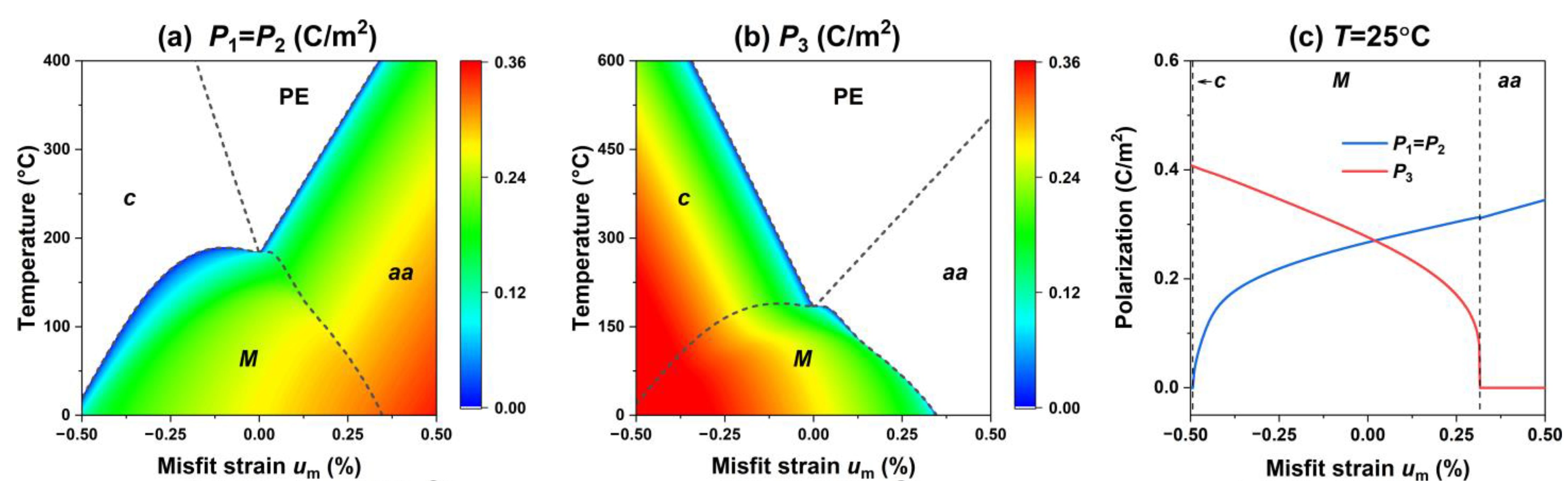
We first investigate the influence of the misfit strain on the phase structures of the PIN–PMN–PT thin films, as shown in Figure 1. Figure 1a,b show that under the in-plane biaxial misfit strain, PIN–PMN–PT thin films may exhibit the four phase structures, and their polarization characteristics are summarized in Table 2. It can be seen that the tetragonal c phase is easily formed under a compressive strain, and the orthorhombic aa phase is more easily formed under a tensile strain. The tetragonal phase c has a polarization along the [001]-direction. In contrast, the monoclinic M phase can exist under both a compressive strain and a tensile strain. At high temperatures, the paraelectric PE phase is formed. To more clearly observe the variation of polarization with the mismatch strain more clearly, the change in the polarization components with the misfit strain at room temperature is plotted in Figure 1c. It can be seen that with the misfit strain change from compressive to tensile, the PIN–PMN–PT films exhibit a tetragonal c phase, monoclinic M phase, and orthorhombic aa phase in turn. The out-of-plane component decreases within the monoclinic M phase. In contrast, the in-plane component exhibits the opposite trend. At room temperature, the c-M phase boundary is around um = −0.49%, while the M-aa phase boundary is around um = 0.315%.
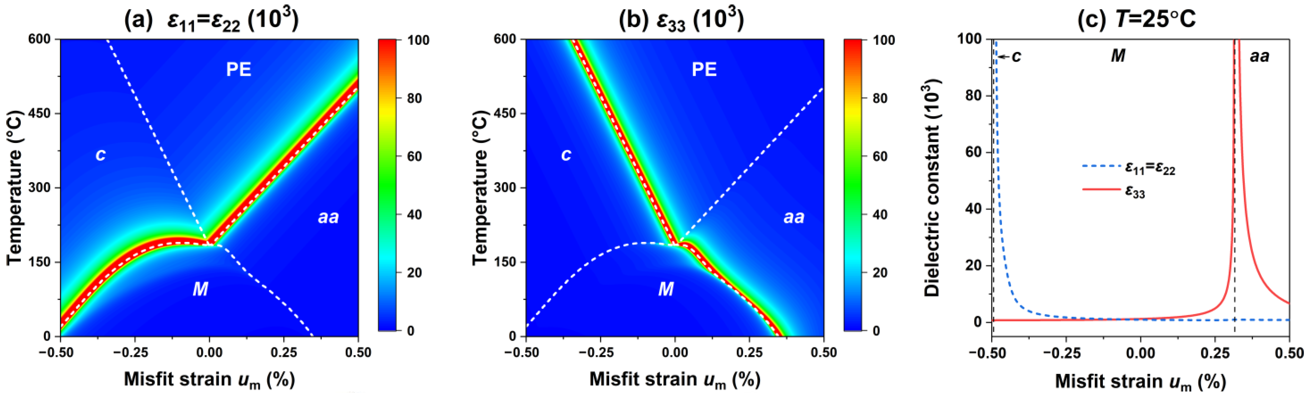
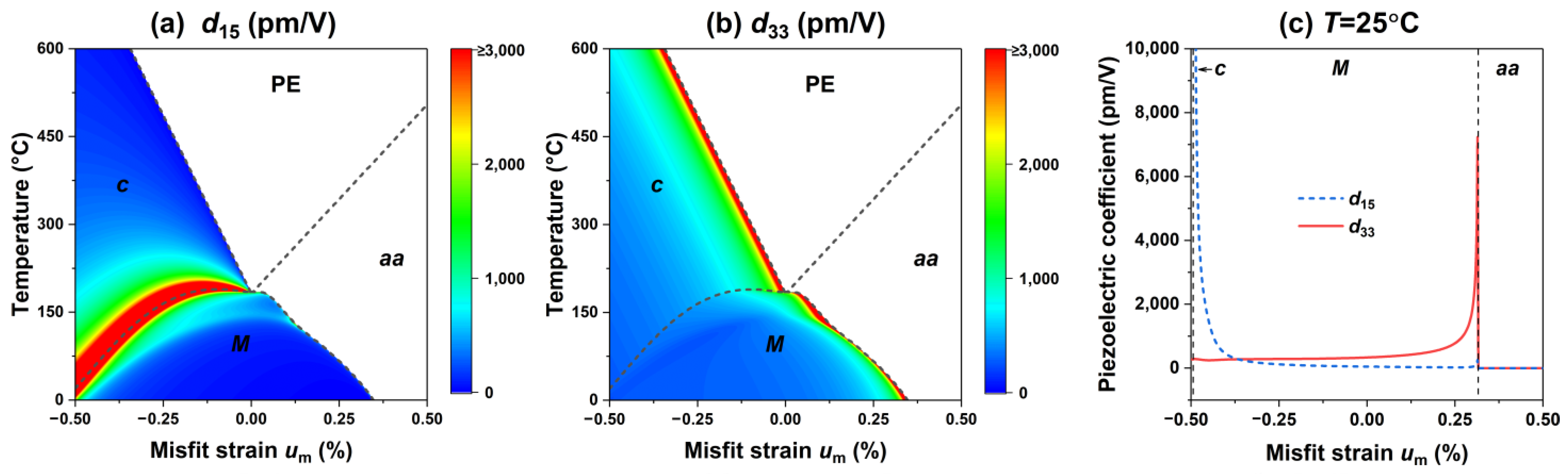
Next, we investigate the influence of the misfit strain on the electromechanical properties of the PIN–PMN–PT thin films, including the dielectric and piezoelectric responses. Figure 2 presents the dielectric constants , , and of the PIN–PMN–PT films at different temperatures and misfit strains. Due to the in-plane biaxial misfit strain on the thin films, it is expected that . Figure 2a shows the excellent transverse permittivity in the vicinity of the c-M phase boundary and the aa-PE phase boundary. Figure 2b shows an excellent longitudinal permittivity in the vicinity of the c-PE phase boundary and the M-aa phase boundary. Figure 2c shows the trend of the dielectric constant at room temperature with respect to the misfit strain. Similarly, the dielectric response enhancement at the phase boundary is also observed in the BaTiO3 [22] and BiFeO3 [24,38] thin films due to the abrupt change in the polarization slope near the phase boundary. The sudden change in the polarization slope also causes the PIN–PMN–PT film to exhibit an excellent piezoelectric response near the phase boundary, as shown in Figure 3a,b, where the c-M phase boundary has an excellent transverse piezoelectric response , the c-PE phase boundary and M-aa phase boundary exhibit an excellent longitudinal piezoelectric response . The piezoelectric response of the PIN–PMN–PT thin film at room temperature is shown in Figure 3c, which reaches a peak at the c-M phase boundary, and a peak at the M-aa phase boundary.
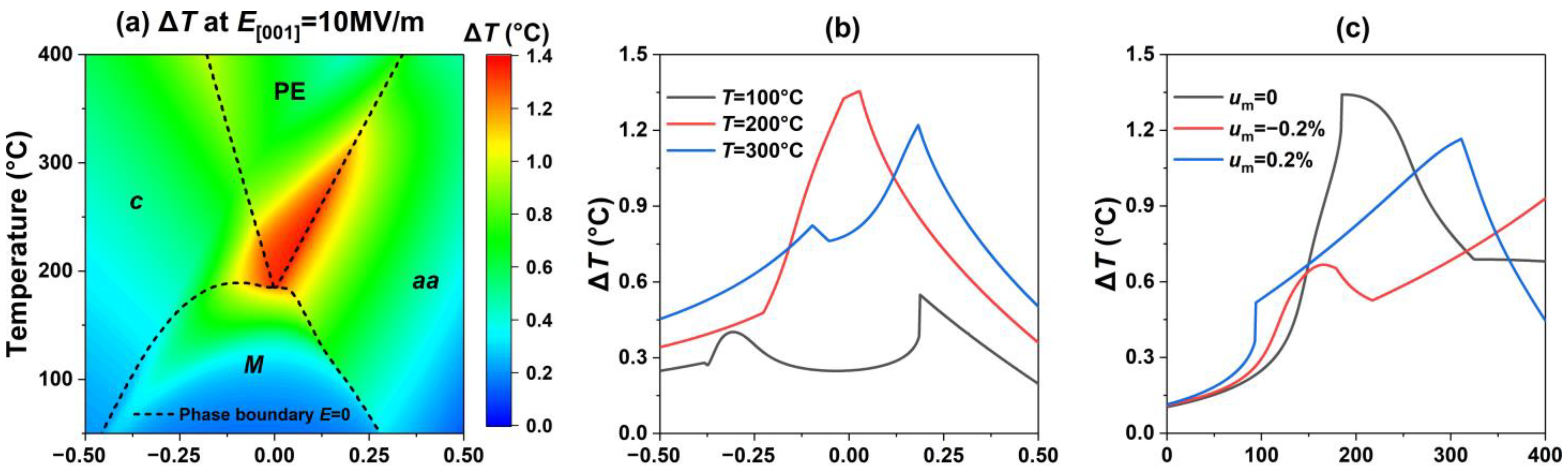
Finally, we investigate the influence of the misfit strain on the adiabatic temperature change ∆T in the electrocaloric response in PIN–PMN–PT thin films, as shown in Figure 4, where the electrical field is applied along the [001] direction with a variation () of 10 MV/m. The results show that large electrocaloric responses ∆T appear near the ferroelectric–paraelectric phase boundary at high working temperature because the dipoles in the paraelectric PE phase are easier to reorient when the external electrical field is changed. The corresponding ∆T at a fixed temperature and under a fixed misfit strain are shown in Figure 4b,c, where the peaks of the EC responses ∆T near the phase boundaries can be observed more clearly, suggesting that an appropriate misfit strain can enhance the EC response of the PIN–PMN–PT thin films.
4. Conclusions
In summary, we adopt a nonlinear thermodynamics analysis to study the influences of misfit strains on the phase structures, electromechanical properties, and electrocaloric responses of epitaxial PIN–PMN–PT thin films. It is found that the PIN–PMN–PT thin films may appear in tetragonal c-, orthorhombic aa-, monoclinic M-, and paraelectric PE phases. We also found that the c-M and aa-PE phase boundaries show a superior dielectric constant, , as well as the c-M phase boundary having a large piezoelectric response, d15, while the c-PE and M-aa phase boundaries show a superior dielectric constant, , and the piezoelectric response d33. The adiabatic temperature change ∆T indicates that the paraelectric–ferroelectric phase boundary shows a large electrocaloric response. The findings offer guidance for PIN–PMN–PT thin film experiments.
Author Contributions
Y.O.: conceptualization, theoretical calculations, and writing the original draft. Y.W.: analysis of the data and review. J.P.: conceptualization, methodology, review, editing, and interpretation of the analyzed data. All authors have read and agreed to the published version of the manuscript.
Funding
This work was partially supported by the National Natural Science Foundation of China (11702092), and the project was supported by the Hunan Provincial Natural Science Foundation of China (2020JJ5182).
Institutional Review Board Statement
Not applicable.
Informed Consent Statement
Not applicable.
Data Availability Statement
Not applicable.
Conflicts of Interest
The authors declare no conflict of interest.
References
- Jiang, P.; Huang, B.; Wei, L.; Yan, F.; Huang, X.; Li, Y.; Xie, S.; Pan, K.; Liu, Y.; Li, J. Resolving fine electromechanical structure of collagen fibrils via sequential excitation piezoresponse force microscopy. Nanotechnology 2019, 30, 205703. [Google Scholar] [CrossRef] [PubMed]
- Zhu, Q.; Pan, K.; Xie, S.; Liu, Y.; Li, J. Nanomechanics of multiferroic composite nanofibers via local excitation piezoresponse force microscopy. J. Mech. Phys. Solids 2019, 126, 76–86. [Google Scholar] [CrossRef]
- Liu, Y.; Seidel, J.; Li, J. Multiferroics under the tip: Probing magnetoelectric coupling at the nanoscale. Natl. Sci. Rev. 2019, 6, 626–628. [Google Scholar] [CrossRef] [Green Version]
- Liu, Y.; Li, J. Seeing is believing: Negative capacitance captured at both nano-and macro-scales. Sci. Bull. 2019, 64, 361–363. [Google Scholar] [CrossRef] [Green Version]
- Bin, C.; Hou, X.; Yang, H.; Liao, L.; Xie, Y.; Wei, H.; Liu, Y.; Chen, X.; Wang, J. Flexible lead-free film capacitor based on BiMg0.5Ti0.5O3-SrTiO3 for high-performance energy storage. Chem. Eng. J. 2022, 445, 136728. [Google Scholar] [CrossRef]
- Chen, C.; Yang, L.; Cheng, Z.; Chang, S.; Jiang, X.; Jiang, X.; Wang, J.; Huang, X.; Gao, X.; Dong, G. Optimization of Ferroelectric Ordering and Thermal Stability in Na1/2Bi1/2TiO3-Based Lead-Free Single Crystal through Defect Engineering. ACS Appl. Mater. Interfaces 2021, 13, 60995–61003. [Google Scholar] [CrossRef]
- Ji, S.; Li, Q.; Wang, D.; Zhu, J.; Zeng, M.; Hou, Z.; Fan, Z.; Gao, X.; Lu, X.; Li, Q. Enhanced energy storage performance and thermal stability in relaxor ferroelectric (1−x)BiFeO3−x(0.85BaTiO3-0.15Bi(Sn0.5Zn0.5)O3) ceramics. J. Am. Ceram. Soc. 2021, 104, 2646–2654. [Google Scholar] [CrossRef]
- Kathavate, V.S.; Prasad, K.E.; Kiran, M.S.R.N. Mechanical characterization of piezoelectric materials: A perspective on deformation behavior across different microstructural length scales. J. Appl. Phys. 2022, 132, 121103. [Google Scholar] [CrossRef]
- Kathavate, V.; Sonagara, H.; Kumar, B.P.; Singh, I.; Prasad, K.E. Direct observations of changes in ferroelectric domain configurations around the indentation and ahead of the crack front in soft-doped PZT. Materialia 2021, 19, 101191. [Google Scholar] [CrossRef]
- Glazounov, A.E.; Kungl, H.; Reszat, J.T.; Hoffmann, M.J.; Kolleck, A.; Schneider, G.A.; Wroblewski, T. Contribution from Ferroelastic Domain Switching Detected Using X-ray Diffraction to R-Curves in Lead Zirconate Titanate Ceramics. J. Am. Ceram. Soc. 2001, 84, 2921–2929. [Google Scholar] [CrossRef]
- Li, F.; Zhang, S.; Xu, Z.; Wei, X.; Luo, J.; Shrout, T.R. Electromechanical properties of tetragonal Pb(In1/2Nb1/2)O3-Pb(Mg1/3Nb2/3)O3-PbTiO3 ferroelectric crystals. J. Appl. Phys. 2010, 107, 54107. [Google Scholar] [CrossRef] [PubMed] [Green Version]
- Qiu, C.; Wang, B.; Zhang, N.; Zhang, S.; Liu, J.; Walker, D.; Wang, Y.; Tian, H.; Shrout, T.R.; Xu, Z. Transparent ferroelectric crystals with ultrahigh piezoelectricity. Nature 2020, 577, 350–354. [Google Scholar] [CrossRef] [PubMed]
- He, N.; Lei, C.; Shan, D.; Li, Q.; Pan, K.; Liu, Y. Phase diagrams and electromechanical properties of polydomain epitaxial (1−x)Pb(Mg1/3Nb2/3)O3–xPbTiO3 thin films. Appl. Phys. Express 2022, 15, 041005. [Google Scholar] [CrossRef]
- Li, F.; Zhang, S.; Yang, T.; Xu, Z.; Zhang, N.; Liu, G.; Wang, J.; Wang, J.; Cheng, Z.; Ye, Z.-G. The origin of ultrahigh piezoelectricity in relaxor-ferroelectric solid solution crystals. Nat. Commun. 2016, 7, 13807. [Google Scholar] [CrossRef] [Green Version]
- He, N.; Li, Q.; Lei, C.; Pan, J.; Shan, D.; Pan, K.; Liu, Y. Electrocaloric response modulated by misfit strain in different oriented epitaxial ferroelectric thin films. Int. J. Solids Struct. 2022, 252, 111808. [Google Scholar] [CrossRef]
- Shkuratov, S.I.; Baird, J.; Antipov, V.G.; Chase, J.B. Generation of giant electric energy density by adiabatically compressed PIN-PMN-PT ferroelectric single crystals. Appl. Phys. Lett. 2021, 118, 122902. [Google Scholar] [CrossRef]
- Shkuratov, S.I.; Baird, J.; Antipov, V.G.; Lynch, C.S.; Zhang, S.; Chase, J.B.; Jo, H.R. Giant power density produced by PIN–PMN–PT ferroelectric single crystals due to a pressure induced polar-to-nonpolar phase transformation. J. Mater. Chem. A 2021, 9, 12307–12319. [Google Scholar] [CrossRef]
- Lin, D.; Li, Z.; Li, F.; Xu, Z.; Yao, X. Characterization and piezoelectric thermal stability of PIN–PMN–PT ternary ceramics near the morphotropic phase boundary. J. Alloys Compd. 2010, 489, 115–118. [Google Scholar] [CrossRef]
- Lv, P.; Wang, L.; Lynch, C.S. A phenomenological thermodynamic energy function for PIN-PMN-PT relaxor ferroelectric single crystals. Acta Mater. 2017, 137, 93–102. [Google Scholar] [CrossRef]
- Webber, K.; Aulbach, E.; Key, T.; Marsilius, M.; Granzow, T.; Rödel, J. Temperature-dependent ferroelastic switching of soft lead zirconate titanate. Acta Mater. 2009, 57, 4614–4623. [Google Scholar] [CrossRef]
- Lei, C.H.; Liu, Y.; Chen, W. Formations and evolutions of martensitic tents and tunnels in shape memory alloy thin films. Mech. Mater. 2019, 134, 9–17. [Google Scholar] [CrossRef]
- Liu, Y.; Li, J. Shear-driven morphotropic phase boundary in epitaxial ferroelectric thin films. Phys. Rev. B 2011, 84, 132104. [Google Scholar] [CrossRef]
- Kathavate, V.; Sonagara, H.; Kumar, B.P.; Singh, I.; Prasad, K.E. Tailoring nanomechanical properties of hard and soft PZT piezoceramics via domain engineering by selective annealing. Mater. Today Commun. 2021, 28, 102495. [Google Scholar] [CrossRef]
- Liu, Y.; Vasudevan, R.K.; Pan, K.; Xie, S.; Liang, W.-I.; Kumar, A.; Jesse, S.; Chen, Y.-C.; Chu, Y.-H.; Nagarajan, V. Controlling magnetoelectric coupling by nanoscale phase transformation in strain engineered bismuth ferrite. Nanoscale 2012, 4, 3175–3183. [Google Scholar] [CrossRef] [PubMed]
- Kannan, V.; Trassin, M.; Kochmann, D.M. Kinetics of ferroelectric switching in poled barium titanate ceramics: Effects of electrical cycling rate. Materialia 2022, 25, 101553. [Google Scholar] [CrossRef]
- Kathavate, V.S.; Kumar, B.P.; Singh, I.; Prasad, K.E. Analysis of indentation size effect (ISE) in nanoindentation hardness in polycrystalline PMN-PT piezoceramics with different domain configurations. Ceram. Int. 2021, 47, 11870–11877. [Google Scholar] [CrossRef]
- Thong, H.; Li, Z.; Lu, J.; Li, C.; Liu, Y.; Sun, Q.; Fu, Z.; Wei, Y.; Wang, K. Domain Engineering in Bulk Ferroelectric Ceramics via Mesoscopic Chemical Inhomogeneity. Adv. Sci. 2022, 9, 2200998. [Google Scholar] [CrossRef]
- Kathavate, V.S.; Sonagara, H.; Kumar, B.P.; Singh, I.; Prasad, K.E. Role of domain configurations on the mechanistic modelling of indentation size effects (ISE) in nanohardness of hard and soft PZT piezoceramics. Int. J. Adv. Eng. Sci. Appl. Math. 2021, 13, 63–78. [Google Scholar] [CrossRef]
- Salem, M.N.; Ding, K.; Rödel, J.; Fang, X. Thermally enhanced dislocation density improves both hardness and fracture toughness in single-crystal SrTiO3. J. Am. Ceram. Soc. 2022, 1–12. [Google Scholar] [CrossRef]
- Liu, Y.; Zhu, Z.; Li, J.-F.; Li, J. Misfit strain modulated phase structures of epitaxial Pb(Zr1−xTix)O3 thin films: The effect of substrate and film thickness. Mech. Mater. 2010, 42, 816–826. [Google Scholar] [CrossRef]
- Pertsev, N.; Zembilgotov, A.; Tagantsev, A. Effect of mechanical boundary conditions on phase diagrams of epitaxial ferroelectric thin films. Phys. Rev. Lett. 1998, 80, 1988. [Google Scholar] [CrossRef]
- Liu, Y.; Yang, L.; Li, J. Strain-engineered orthorhombic-rhombohedral phase boundary in epitaxial bismuth ferrite films. J. Appl. Phys. 2013, 113, 183524. [Google Scholar] [CrossRef]
- Zhou, Y.; Li, Q.; Zhuo, F.; Yan, Q.; Zhang, Y.; Chu, X. Anisotropic field induced phase transitions and negative electrocaloric effect in rhombohedral Mn doped Pb(In1/2Nb1/2)O3-Pb(Mg1/3Nb2/3)O3-PbTiO3 single crystals. Ceram. Int. 2018, 44, 9045–9052. [Google Scholar] [CrossRef]
- Shan, D.; Pan, K.; Liu, Y.; Li, J. High fidelity direct measurement of local electrocaloric effect by scanning thermal microscopy. Nano Energy 2020, 67, 104203. [Google Scholar] [CrossRef]
- Shan, D.; Lei, C.; Cai, Y.; Pan, K.; Liu, Y. Mechanical control of electrocaloric response in epitaxial ferroelectric thin films. Int. J. Solids Struct. 2021, 216, 59–67. [Google Scholar] [CrossRef]
- Lei, C.H.; Liu, Y. Correlations between local electrocaloric effect and domains in ferroelectric crystals. Appl. Phys. Lett. 2022, 121, 102902. [Google Scholar] [CrossRef]
- Pirc, R.; Kutnjak, Z.; Blinc, R.; Zhang, Q. Electrocaloric effect in relaxor ferroelectrics. J. Appl. Phys. 2011, 110, 074113. [Google Scholar] [CrossRef] [Green Version]
- Peng, J.; Li, Q.; Shan, D.; Pan, K.; Yu, G.; Liu, Y. Phenomenological thermodynamic potentials for bulk and thin-film Ba(Zr0.08Ti0.92)O3 single crystals. J. Appl. Phys. 2016, 119, 204103. [Google Scholar] [CrossRef]
Figure 1.
(a,b) The misfit strain-temperature phase diagrams in the absence of external electric field, and the corresponding (a) in-plane polarization components P1, P2, and (b) the out-of-plane polarization components P3. (c) The corresponding polarization components as functions of misfit strain um at room temperature. The color bar illustrates the value of polarization.

Figure 2.
The dielectric constants (a) and , and (b) as a function of misfit strain and temperature. (c) The corresponding dielectric constants as functions of misfit strain um at room temperature.
Figure 2.
The dielectric constants (a) and , and (b) as a function of misfit strain and temperature. (c) The corresponding dielectric constants as functions of misfit strain um at room temperature.

Figure 3.
The piezoelectric coefficients (a) d15, and (b) d33 as a function of misfit strain and temperature. (c) The corresponding piezoelectric coefficients as function of misfit strain um at room temperature.
Figure 3.
The piezoelectric coefficients (a) d15, and (b) d33 as a function of misfit strain and temperature. (c) The corresponding piezoelectric coefficients as function of misfit strain um at room temperature.

Figure 4.
(a) The electrocaloric temperature change ∆T as a function of misfit strain and temperature under an electric field change ∆E = 10 MV/m. (b) The corresponding ∆T at a fixed temperature. (c) The corresponding ∆T at fixed misfit strain.
Figure 4.
(a) The electrocaloric temperature change ∆T as a function of misfit strain and temperature under an electric field change ∆E = 10 MV/m. (b) The corresponding ∆T at a fixed temperature. (c) The corresponding ∆T at fixed misfit strain.

Table 2.
The polarization components of the epitaxial PIN–PMN–PT thin films in the absence of an external electric field.
Table 2.
The polarization components of the epitaxial PIN–PMN–PT thin films in the absence of an external electric field.
| Phase | Polarization |
|---|---|
| Paraelectric PE | P1 = P2 = P3 = 0 |
| Tetragonal c | P1 = P2 = 0, P3 ≠ 0 |
| Orthorhombic aa | P3 = 0, |P1| = |P2| ≠ 0 |
| Monoclinic M | |P1| = |P2| ≠ 0, P3 ≠ 0 |
Publisher’s Note: MDPI stays neutral with regard to jurisdictional claims in published maps and institutional affiliations. |
© 2022 by the authors. Licensee MDPI, Basel, Switzerland. This article is an open access article distributed under the terms and conditions of the Creative Commons Attribution (CC BY) license (https://creativecommons.org/licenses/by/4.0/).
Share and Cite
MDPI and ACS Style
Ou, Y.; Wu, Y.; Peng, J. Misfit-Strain Phase Diagram, Electromechanical and Electrocaloric Responses in Epitaxial PIN–PMN–PT Thin Films. Materials 2022, 15, 7660. https://doi.org/10.3390/ma15217660
AMA Style
Ou Y, Wu Y, Peng J. Misfit-Strain Phase Diagram, Electromechanical and Electrocaloric Responses in Epitaxial PIN–PMN–PT Thin Films. Materials. 2022; 15(21):7660. https://doi.org/10.3390/ma15217660
Chicago/Turabian StyleOu, Yun, Yingying Wu, and Jinlin Peng. 2022. "Misfit-Strain Phase Diagram, Electromechanical and Electrocaloric Responses in Epitaxial PIN–PMN–PT Thin Films" Materials 15, no. 21: 7660. https://doi.org/10.3390/ma15217660
Note that from the first issue of 2016, this journal uses article numbers instead of page numbers. See further details here.