
Effects of Thermal Conductive Materials on the Freeze-Thaw Resistance of Concrete
by
 , ,
, ,
Byeong-Hun Woo
1 ,
,
Dong-Ho Yoo
1,
Seong-Soo Kim
2,
Jeong-Bae Lee
3,
Jae-Suk Ryou
1 and
Hong-Gi Kim
1,* 1
Civil and Environmental Engineering Department, Hanyang University, Jaesung Civil Engineering Building, 222 Wangsimni-ro, Seongdong-Gu, Seoul 04763, Korea
2
Department of Civil Engineering, Daejin University, 1007 Hoguk-ro, Pocheon-si 11159, Korea
3
GFC R&D Co., Ltd., 155 Hoguk-ro, Pocheon-si 11158, Korea
*
Author to whom correspondence should be addressed.
Materials 2021, 14(15), 4063; https://doi.org/10.3390/ma14154063
Submission received: 11 June 2021
/
Revised: 9 July 2021
/
Accepted: 20 July 2021
/
Published: 21 July 2021
(This article belongs to the Special Issue Functional Cement-Based Composites for Civil Engineering)
Abstract
:To solve the problem of black ice, many studies are being carried out. The key in recent days is enhancing the thermal conductivity of concrete. In this study, to improve the thermal conductivity, silicon carbide was used to substitute 50% and 100% of the fine aggregate. In addition, steel fiber is not only for enhancing the mechanical properties but could enhance thermal conductive material. Hence, the arched-type steel fiber was used up to a 1% volume fraction in this study. Furthermore, graphite was used for 5% of the volume fraction for enhancing the thermal conductivity. However, thermal damage would occur due to the difference in thermal conductivity between materials. Therefore, the thermal durability must be verified first. The target application of the concrete in this study was its use as road paving material. To evaluate the thermal durability, freeze–thaw and rapid cyclic thermal attacks were performed. The thermal conductivity of the specimens was increased with the increase in thermal conductive materials. Graphite has already been reported to have a negative effect on mechanical properties, and the results showed that this was the case. However, the steel fiber compensated for the negative effect of graphite, and the silicon carbide provided a filler effect. Graphite also had a negative effect on the freeze–thaw and rapid cyclic thermal attack, but the steel fiber compensated for the reduction in thermal durability. The silicon carbide also helped to improve the thermal durability in the same way as steel fiber. Comprehensively, the steel fiber enhanced all of the properties of the tests. Using 100% silicon carbide was considered the acceptable range, but 50% of silicon carbide was the best. Graphite decreased all the properties except for the thermal conductivity. Therefore, the content of graphite or using other conductive materials used should be carefully considered in further studies.
1. Introduction
Cold regions have two kinds of threatening factors for vehicle users. One is black ice and the other is pot-holes caused by the freeze–thaw cycle. Black ice makes the surface of the road slippery and causes traffic accidents [1]. To prevent the generation of black ice, people use chemical salts such as CaCl2 [2,3,4]. However, it was demonstrated that chemical salts bring about the deterioration of concrete and reduce the service life of the concrete [2]. In particular, Matalkah et al. [4] showed that the combination of freeze–thaw conditions and chemical salts accelerated the deterioration of concrete. Thus, researchers devised heating systems for reducing the use of chemical salts and preventing the formation of black ice [5,6,7]. The studied pavement heating systems showed a good performance on snow-melting; however, the big problem was that reaching time to the surface of pavement took a long time [5,6,7]. To overcome this problem, research was conducted to enhance the thermal conductivity of the materials themselves. Representative cases include the application of Carbon Nanofibers (CNFs) and Carbon Nanotubes (CNTs) [8,9,10,11,12,13]. Although CNFs/CNTs have a superior thermal conductivity of 3000 to 6000 W/mK [11], there were critical limits to improve the thermal conductivity of the cement composites. Because CNFs/CNTs are a kind of fiber, therefore the CNFs/CNTs could not apply up to 2% of the volume fraction [8,9,10,11,12,13]. In addition, CNFs/CNTs should separate each element using physical or chemical methods because of the Van der Waals force [8].
Graphite has good thermal conductivity because graphite is a kind of carbon material and has been extensively investigated by researchers [14,15,16]. However, it is reported that the mechanical properties are significantly decreased by using graphite above 5% of volume fraction [17,18]. In addition, the other problem of using CNFs/CNTs and graphite is the cost. To overcome the limits of previous studies, the substitution method was applied to this study because the aggregate occupies more than 65% of the volume fraction [19]. Silicon carbide (SiC) was chosen as the substituting material of the fine aggregate; as SiC has good thermal conductivity and hardness, it is considered sufficient as a fine aggregate substitution material [20,21,22].
In this study, SiC was substituted for 50% and 100% of fine aggregate in order to improve the thermal conductivity. In addition, graphite was used at 5% of volume for enhancing the thermal conductivity, and the arched-type steel fiber was used for compensating the reduction in mechanical properties by the graphite [23,24,25,26,27]. Furthermore, steel fiber could be used as the thermal conductive material because the steel fiber has a high level of thermal conductivity [28]. Due to applying the various thermal conductive materials to the concrete, thermal damage would be generated by the difference in the thermal conductivity of each material in the cold environment, e.g., via freeze–thaw [29].
The concrete introduced in this study was intended for use as road pavement, which meant it was necessary for the thermal durability performance in conditions such as freeze–thaw to be verified. Therefore, the purpose of this study is to assess the thermal durability of the concrete with thermal conductive materials. To assess the thermal durability, two main experiments were performed: freeze–thaw (FT) and rapid cyclic thermal attack (RCTA). The concrete used in this study was made for application as road paving material, therefore, the FT resistance was important. In addition, cold regions usually change the air temperature very rapidly. Therefore, the RCTA test was essential for assessing the thermal durability of concrete.
2. Materials and Experiments
2.1. Materials
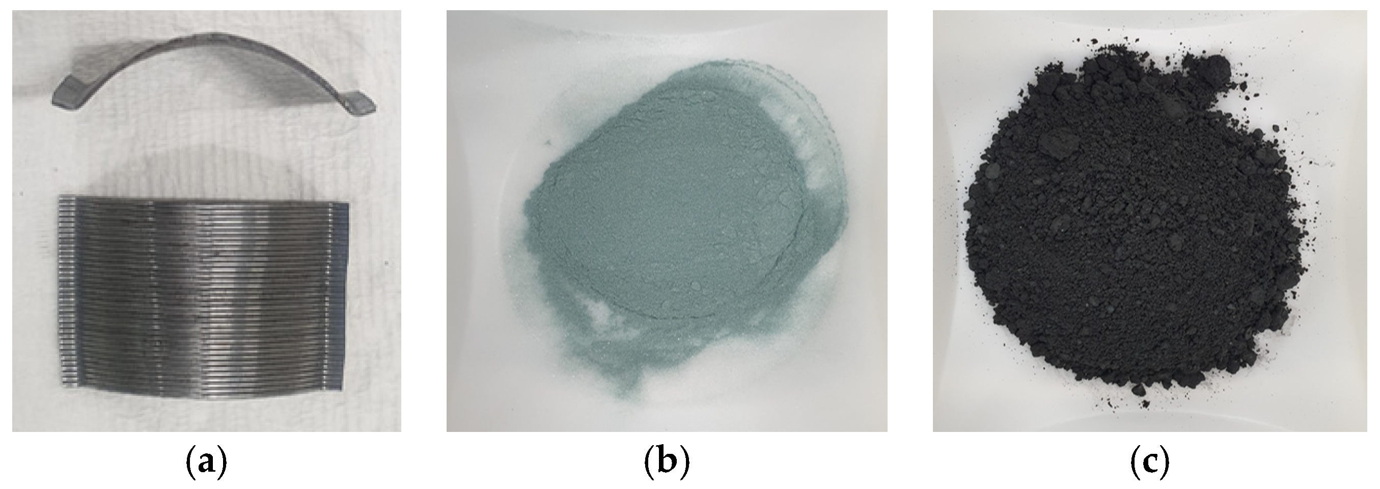
In this study, Ordinary Portland Cement (OPC) [30], graphite, SiC, and steel fiber were mainly used (Figure 1). The chemical composition of OPC is indicated in Table 1. The properties of graphite are indicated in Table 2 and the properties of SiC are summarized in Table 3. Steel fiber that has an arched shape was used and the details are in Table 4.
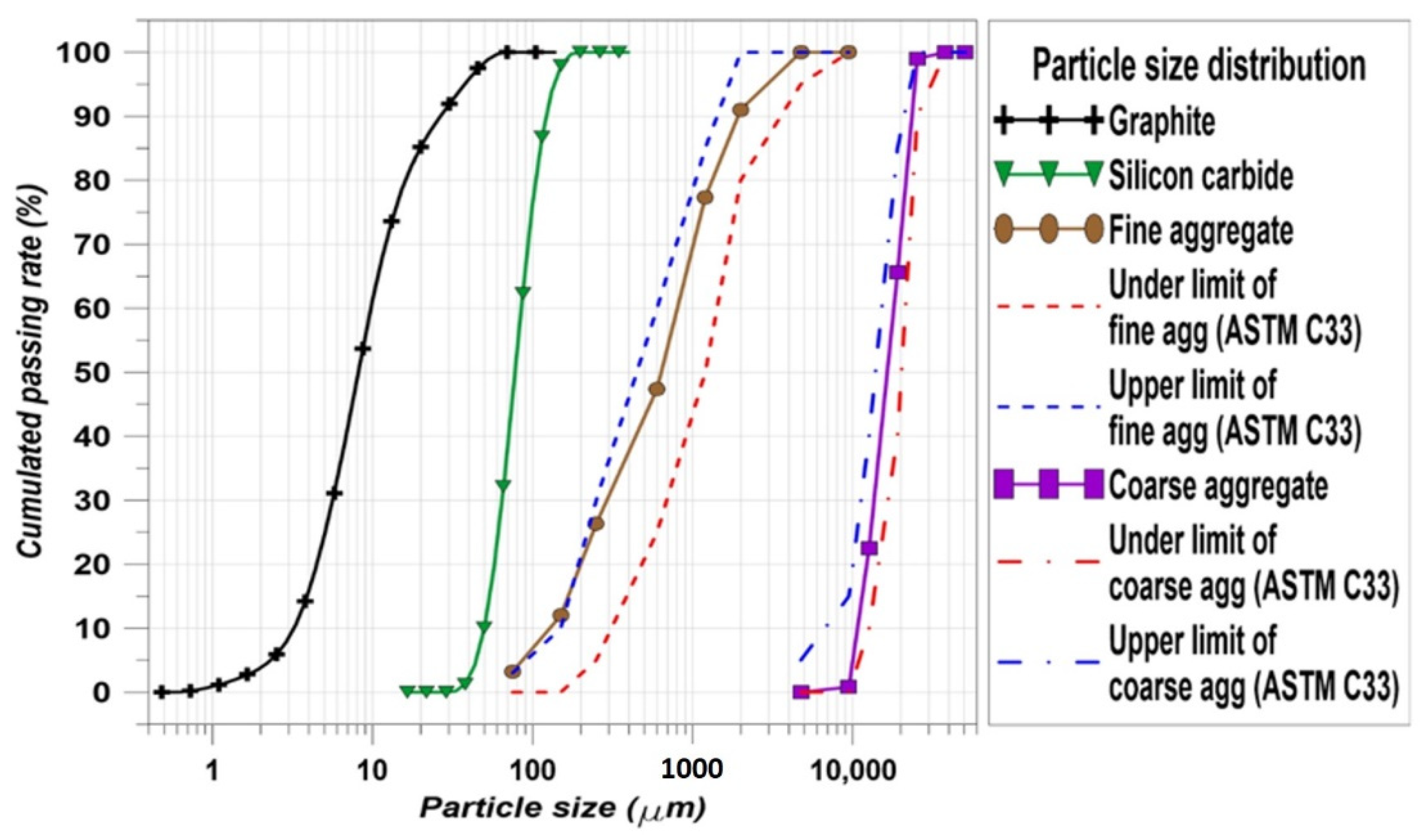
The fine and coarse aggregates used natural sand and crushed stone, respectively. The specific gravity of the fine aggregate was 2.62 ton/m3 and the coarse aggregate was 2.71 ton/m3. Except for the OPC, graphite, SiC, the fine aggregate, and the coarse aggregate have their own particle size distribution (PSD). The PSD properties of each material are important to investigate how the concrete is made well. The PSDs of graphite, SiC, the fine aggregate, and the coarse aggregate are indicated in Figure 2. In particular, there is a standard for fine and coarse aggregates [31]. ASTM C33 [31] recommends the PSD upper and lower limits for the aggregates. According to the PSDs of the fine and coarse aggregates in this study, the particle distributions of the aggregates are located between the upper and lower limits. Therefore, it can be considered that the conditions of the aggregates are acceptable.
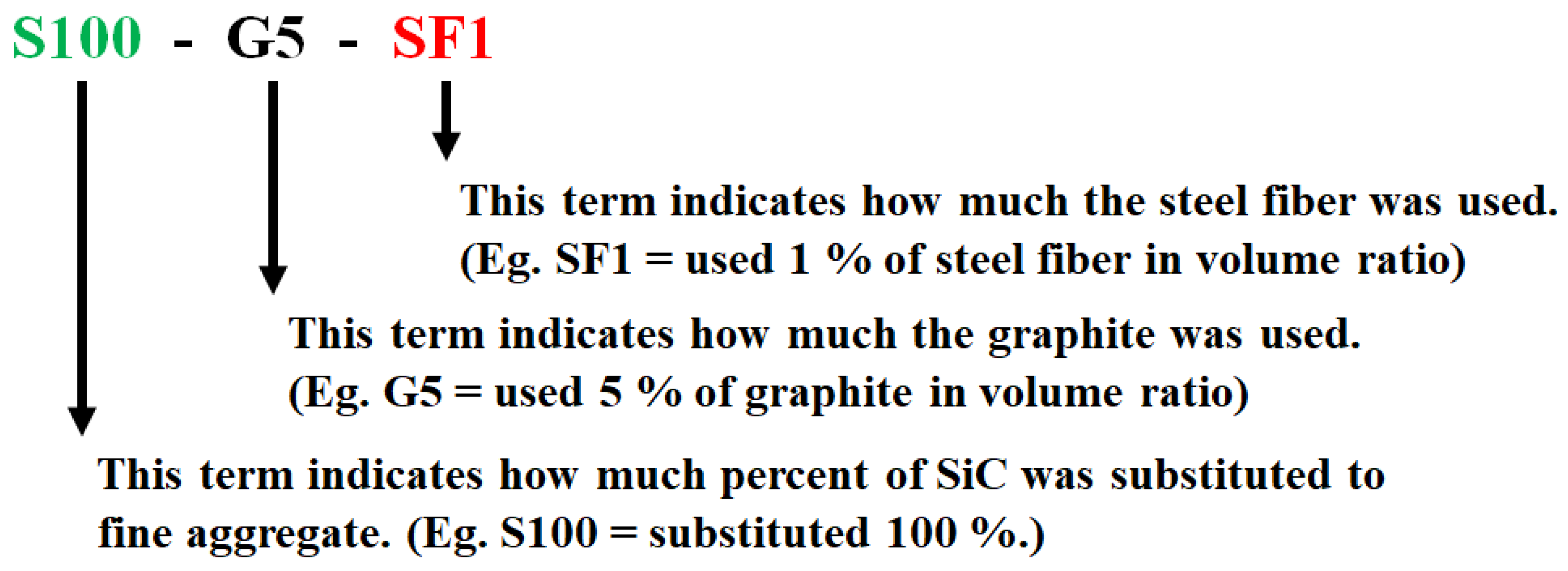
A total 6 cases of concrete specimens were cast. The specimens were cured for one day in air and demolded after one day of curing. After demolding, the specimens were immersed in the water at 25 ℃ for 27 days (total 28 days curing). The mixing properties of the specimens are summarized in Table 5 and the naming details of the specimens are indicated in Figure 3.
2.2. Experiments
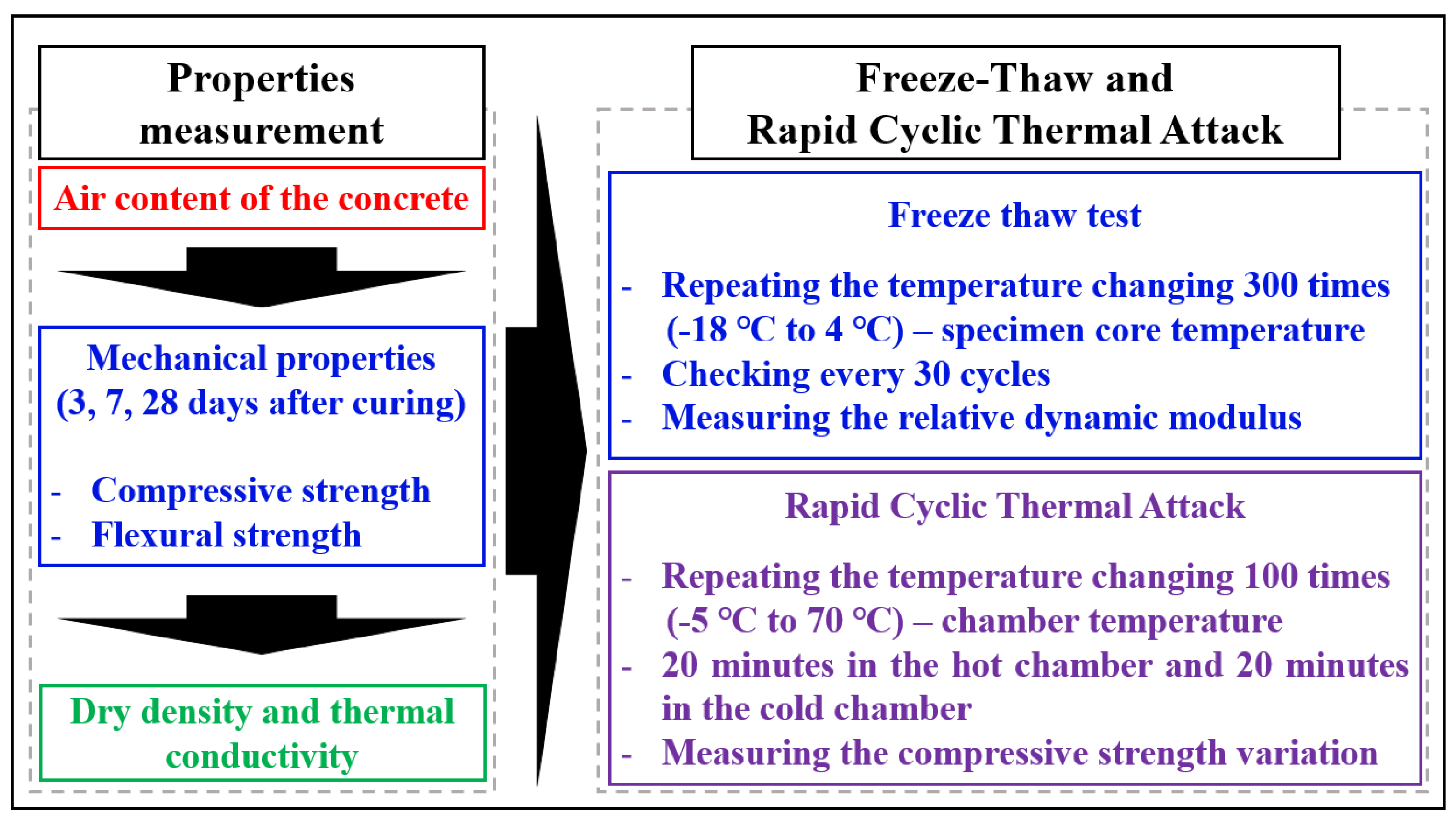
The main experiments were the FT cycle test and RCTA and the supporting experiment was strength test and thermal properties. The detail of the research flow is indicated in Figure 4.
According to Figure 4, the air content of the specimens is the fresh property of concrete, and this is important to the FT test. There is a wide range of air content and the range of 3.5 to 4.5% is commonly used [32]. The target air content of this study was 4% in each specimen, and the results of the air content are indicated in Table 6. The acceptable range of the air content was 4% ± 0.5%.
2.2.1. Compressive Strength Test
The compressive strength was measured at 3, 7, and 28 days of curing. In addition, the stress–strain curve was measured at 28 days of curing in each specimen. Test procedure followed ASTM standard [33]. When measuring the stress–strain curve, a universal testing machine (UTM) which has 200 tons of load capacity (Shimadzu, CCM-200A, Shimadzu Corporation, Japan) was used for measuring the compressive strength. In addition, the strain sensor, which has a 0.6% sensitivity, was used for measuring the concrete strain (Tokyo Measuring Instruments Lab (TML), PL-60-11-3LJC-F: One gauge—three wires, Tokyo Measuring Instruments Laboratory Corporation, Tokyo, Japan). From the test method, the static elastic modulus could be measured by using the result data. The calculation of elastic modulus followed Equation (1) [34].
where, E is the elastic modulus (MPa), S0.4 is the stress corresponding to 40% of ultimate stress (MPa), is the stress corresponding to a longitudinal strain of of 0.00005 (MPa), is the longitudinal strain produced by the S0.4, and is the strain value of 0.00005.
2.2.2. Flexural Strength Test
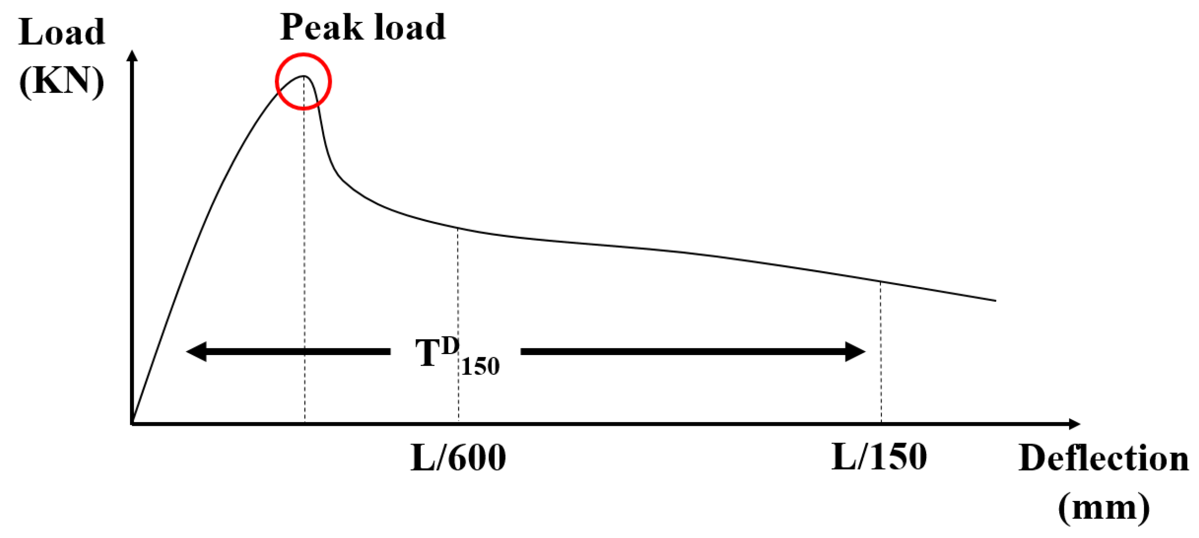
The flexural strength was measured at the same curing ages as the compressive strength. The load–deflection curve was measured at 28 days of curing in each specimen and followed the test method of ASTM [35]. In this standard [35], there are two types of strength calculations: peak flexural strength and equivalent flexural strength. Due to the fiber reinforcing to the concrete, the behavior after cracking should be considered. Therefore, the equivalent flexural strength should be calculated. The flexural strength was calculated by Equation (2) [35].
where, is the flexural strength (MPa), is the load (N), is the length of span (mm), is the width of the specimen section (mm), and is the height of the specimen section (mm). According to Figure 5, The deflection points of L/600 and L/150 are important to calculate the equivalent flexural strength.
The flexural test was conducted in the case of the 4-point bending test and the spans (L) were 300 mm in this experiment. Therefore, the checking points of net deflection in Figure 5 were 0.5 mm and 2 mm. The calculation of equivalent flexural strength was followed Equation (3) [35].
where, is the equivalent flexural strength (MPa) and is the area of the load–deflection curve from 0 to L/150 (N mm). The same UTM as the compressive strength was used to measure the flexural strength.
2.2.3. Dry Density
Thermal conductive materials were used in this study. Therefore, the thermal conductivity was measured. Before considering the thermal conductivity of the specimens, the dry density has to be considered because the thermal conductivity is sensitive to the density of materials. There is a simple standard for measuring the dry density and water absorption following standard [36]. The size of the specimen was 100 mm in diameter and 50 mm in height. Specimens were immersed in the de-ionized water for 3 days and dried for 2 days at 80 °C in a dry chamber.
2.2.4. Thermal Conductivity
It is important to measure the thermal conductivity because thermal conductive materials were used in this study. There are many methods used to measure the thermal conductivity of cement composites [37]. However, we chose a simple method involving the use of a machine: Isomet-2114 (Applied Precision, Bratislava, Slovakia) [38,39,40]. Isomet-2114 is widely used to measure the thermal conductivity of the concrete specimens and the results are accurate. When measuring the thermal conductivity, the cylindrical specimens were used that had a size of 100 mm in diameter and 50 mm in height.
2.2.5. Freeze–Thaw Test
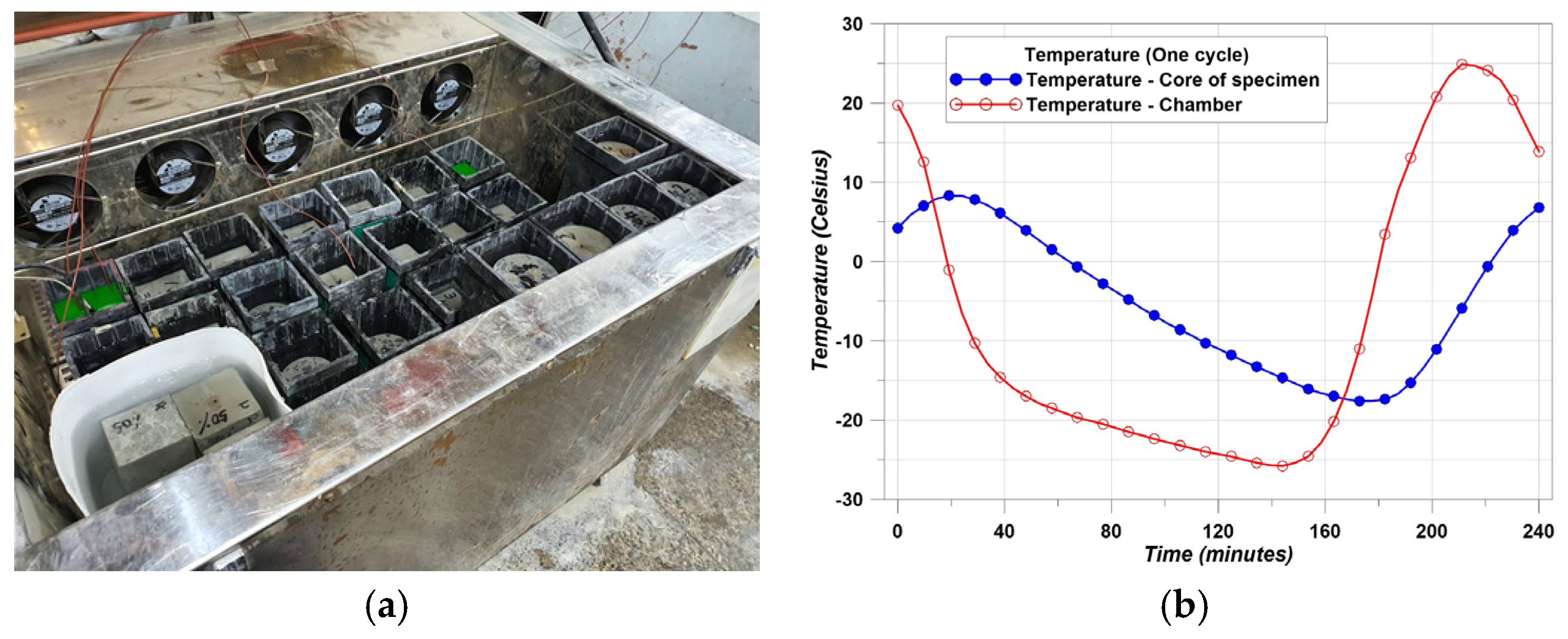
The concrete made with thermal conductive materials was intended for use as concrete pavement on the road. Therefore, freeze–thaw resistance is an important factor for road users. Figure 6a shows the freeze–thaw chamber and Figure 6b shows the cycle of temperature. Figure 6b shows the real test data.
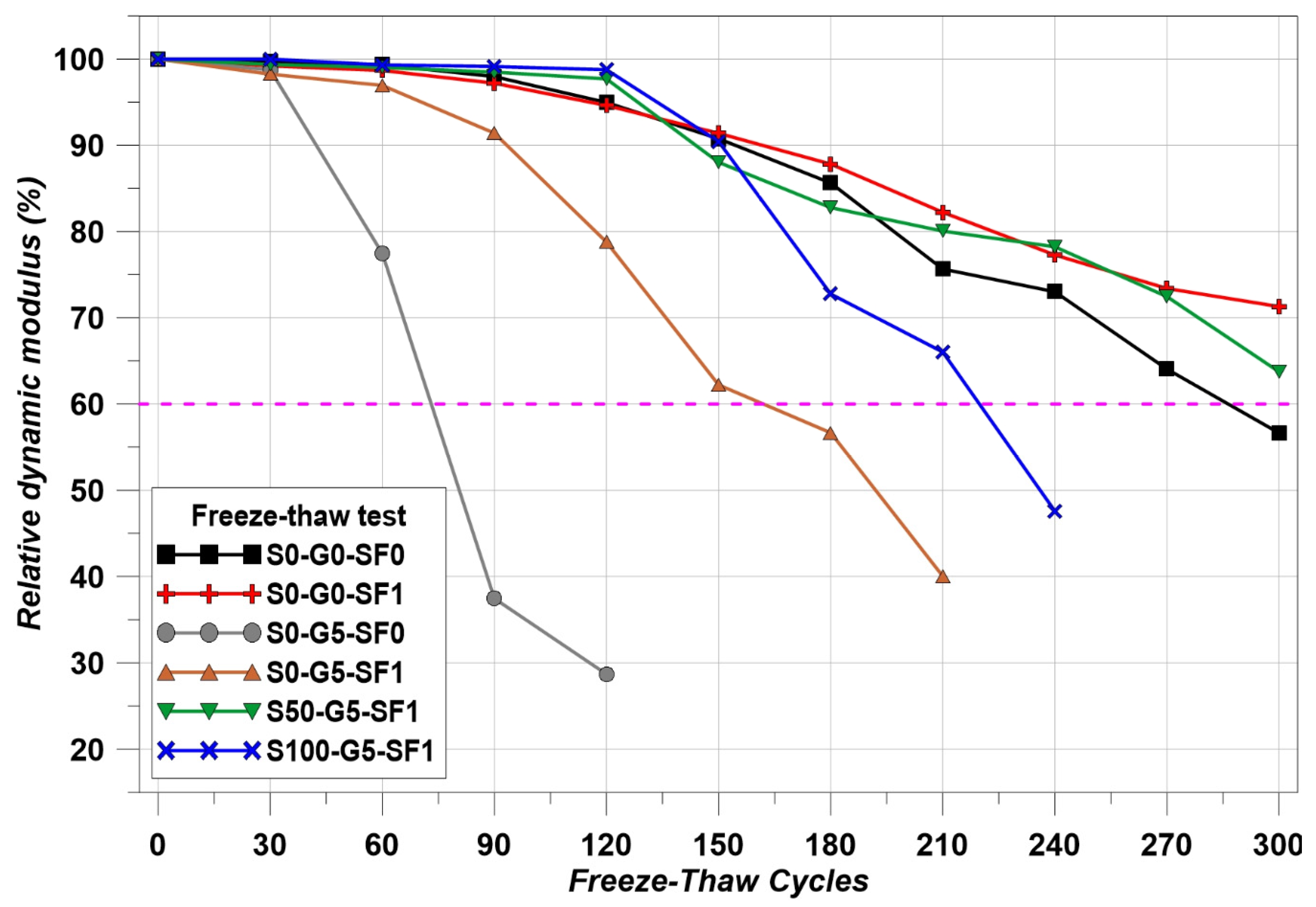
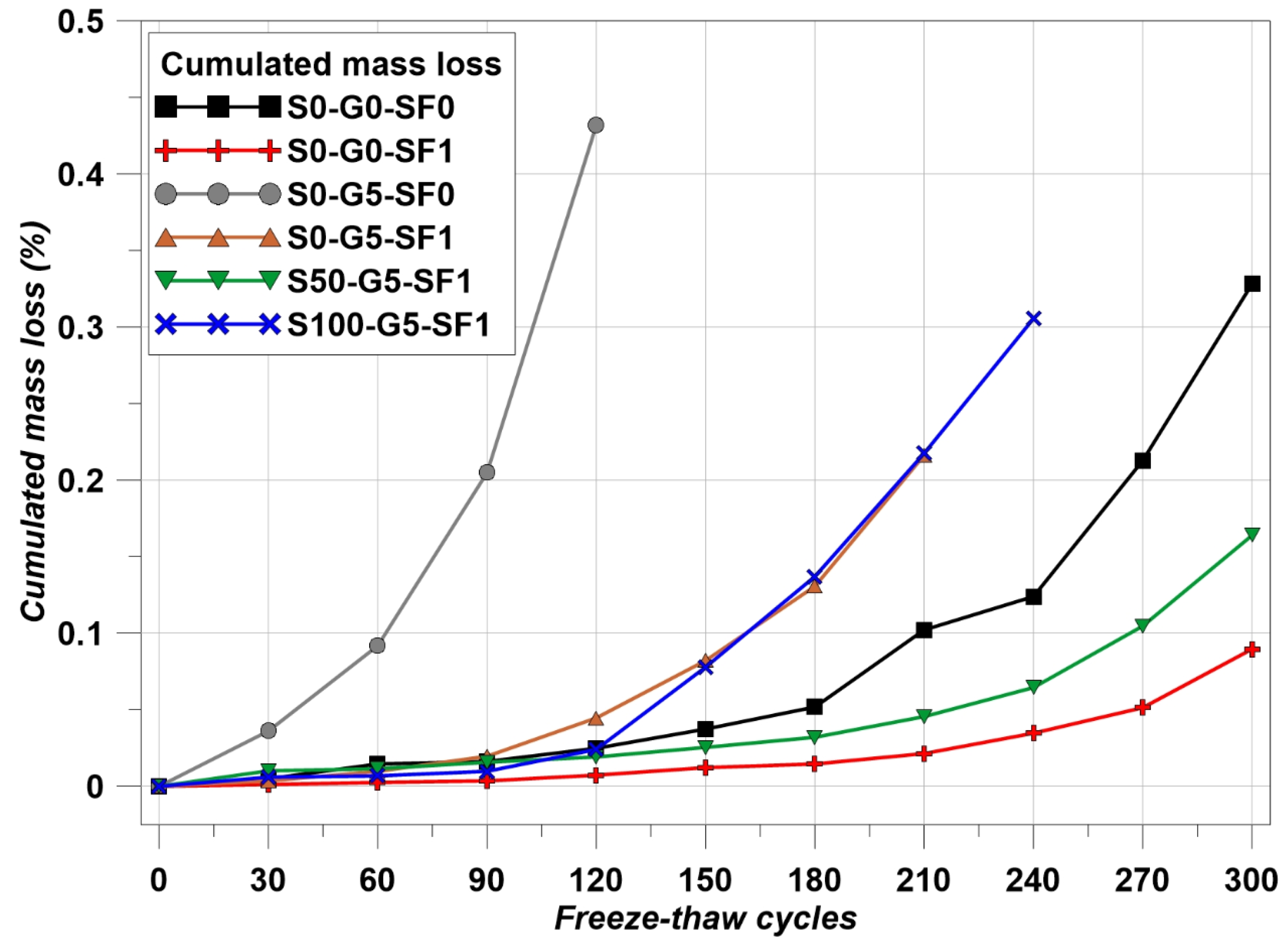
The temperature cycle has to meet the condition that the core temperature of the specimens should repeat −18 ± 2 ℃ to 6 ± 2 ℃ for 4 h in one cycle. The cycle was repeated a total of 300 times and the Relative Dynamic Modulus (RDM) was measured every 30 cycles. In addition, mass loss was measured every 30 cycles. The test method followed the ASTM standard [41] and followed Equation (4) in order to calculate RDM.
where, is RDM (%), is the measured frequency after m cycles of FT, and is the measured frequency at 0 cycles of FT.
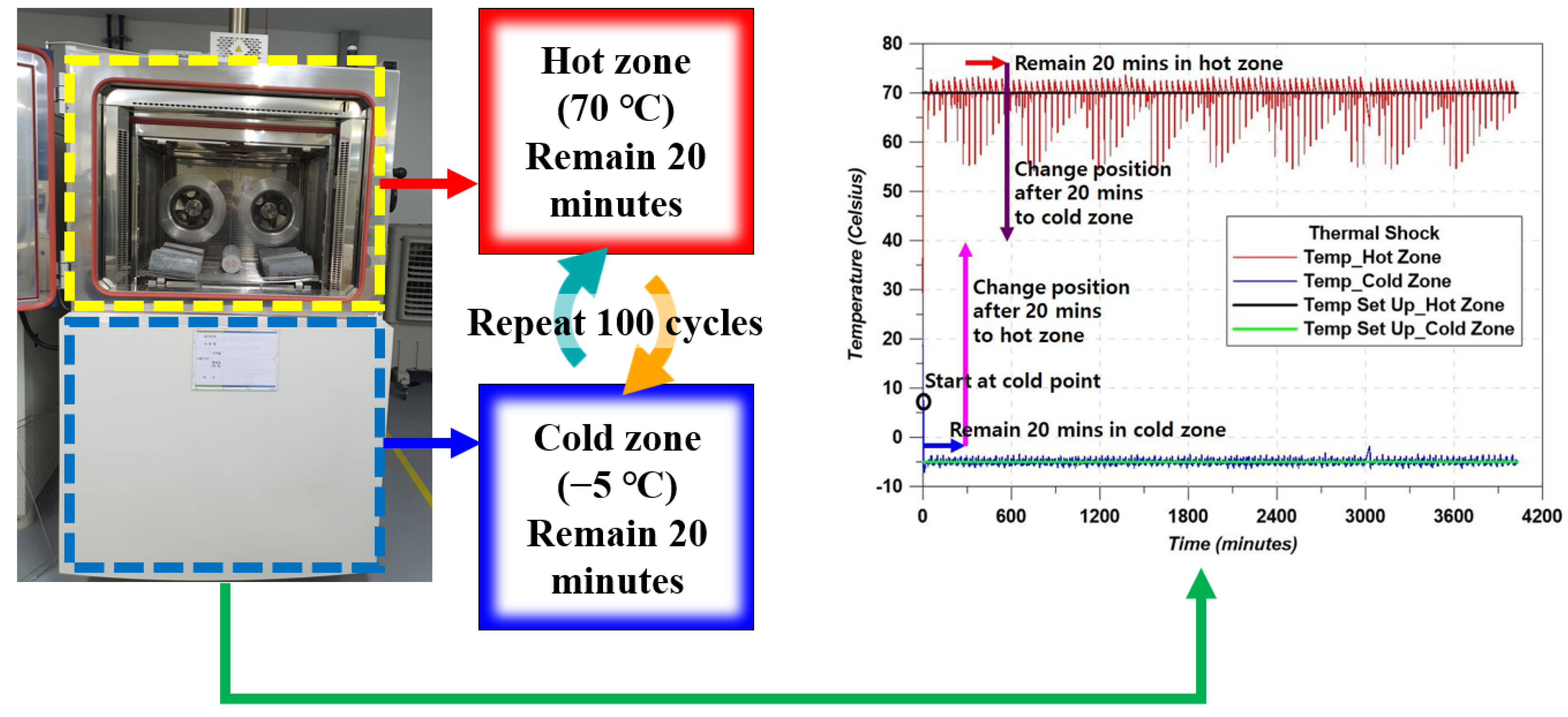
2.2.6. Rapid Cyclic Thermal Attack Test
Due to the difference in the thermal conductivity of each material, it is impossible to neglect the effect of thermal damage. This test is similar to the FT test, but the applied conditions and the concept were different. The purpose of this test is to show how well the specimens resist harsh thermal conditions. The test concept is indicated in Figure 7. The mechanical variation was evaluated by performing the compressive test with the stress–strain curve.
3. Results and Discussion
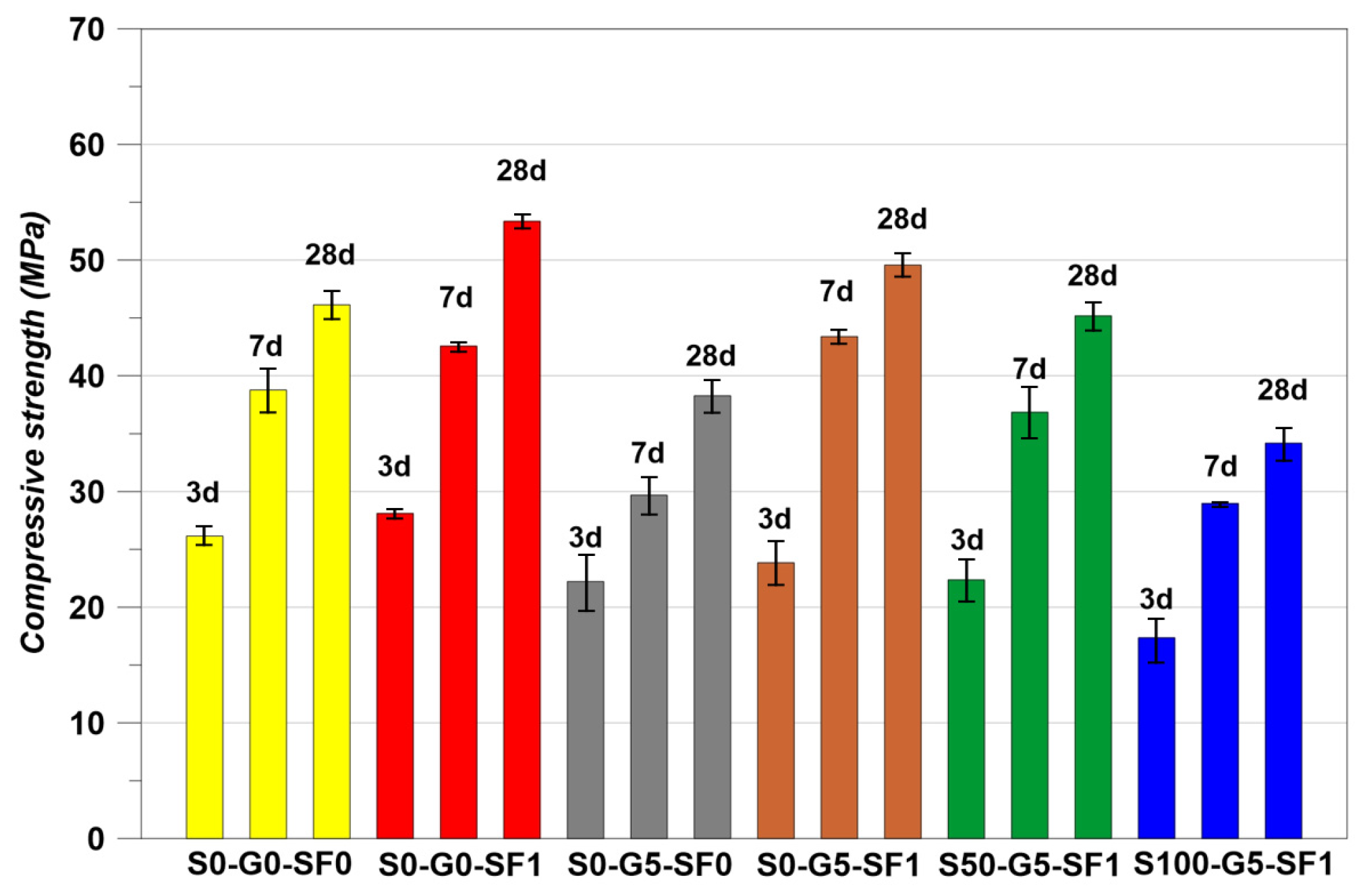
3.1. Compressive Strength Restuls
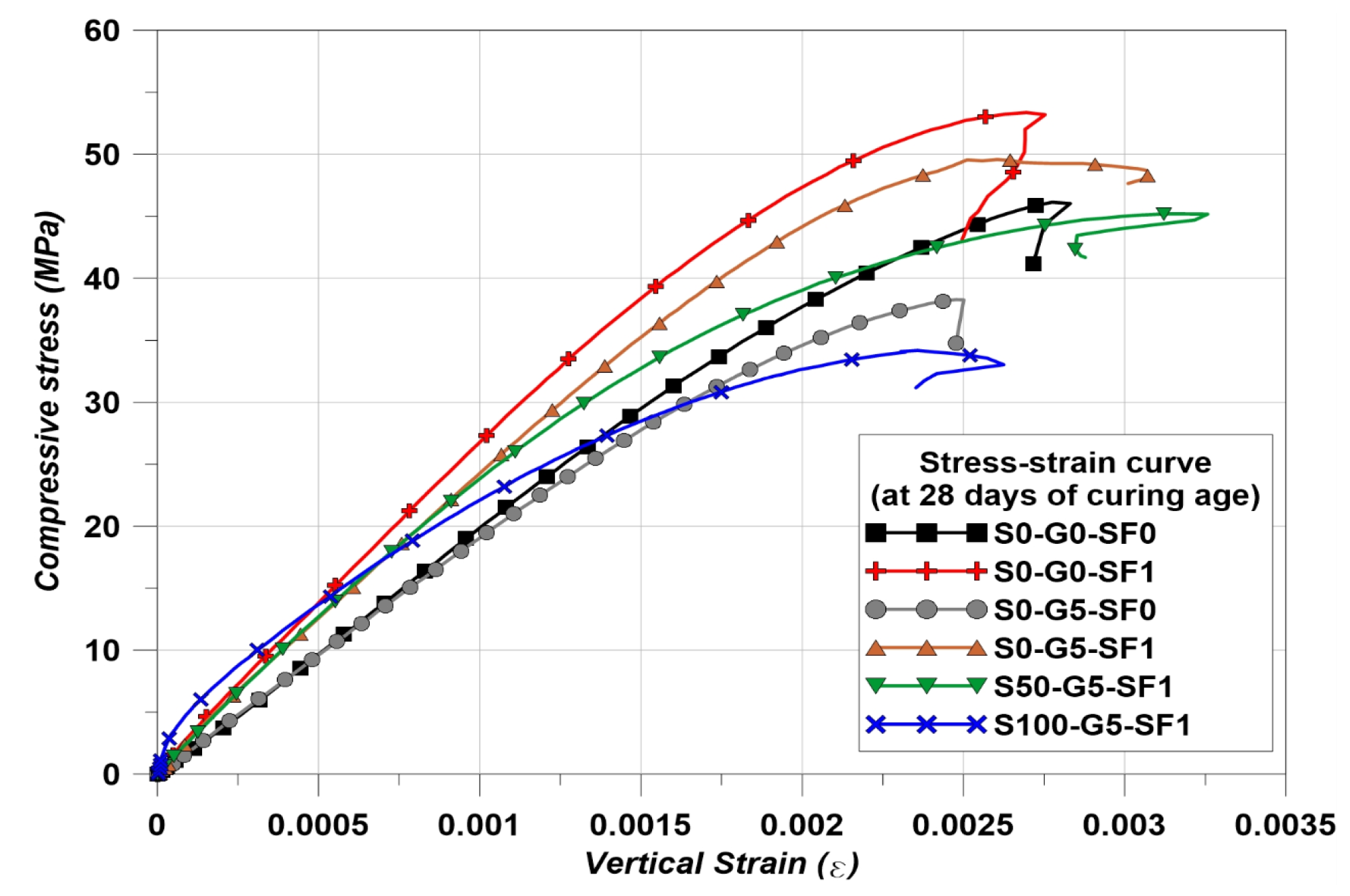
The compressive strength results are indicated in Figure 8 and the stress–strain curves of the specimens at the 28 days of curing are indicated in Figure 9. The S0-G0-SF1 showed the best compressive performance. The cases using steel fiber in concrete have been reproduced many times and have reported that using steel fiber brings an increase in compressive strength [42,43,44]. The S0-G5-SF0 showed less strength than S0-G0-SF0. Many studies showed that graphite has a negative effect on the mechanical strength of concrete [14,15,16,17,18,28]. In addition, a significant decrease in mechanical properties could be found when the graphite used more than 10% of the volume fraction [14,15,16,17,18,28]. Although the mechanical properties are decreased when using graphite, there is an advantage for the thermal conductivity. Therefore, the 5% of volume fraction was chosen for use in the graphite used in this study [14,15,16,17,18,28]. The S0-G5-SF1 specimen showed higher compressive strength than S0-G0-SF0. However, S0-G5-SF1 showed less strength than S0-G0-SF1. This is the same reason for the studies of graphite [14,15,16,17,18,28]. In addition, using SiC as a fine aggregate up to 50% showed the almost same compressive performance compared to the normal cement composites [45]. However, the S50-G5-SF1 showed a slightly smaller value than S0-G0-SF0 and this was considered a result of graphite used. The S100-G5-SF1 showed the lowest value. A study showed that the mechanical properties decreased when using 100% SiC as fine aggregate [45].
Table 7 is indicating the measured elastic modulus of the specimens. The S0-G5-SF0 showed the lowest elastic modulus value. However, the S100-G5-SF1 showed the lowest compressive strength. The other specimens showed that the elastic modulus was increased with the increase in compressive strength. However, the S0-G5-SF0 and S100-G5-SF1 specimens showed a different trend in the results of elastic modulus. This phenomenon could be explained in Figure 9. S0-G5-SF0 did not use steel fiber. Therefore, this specimen could be treated as a brittle material. Hence, the initial strain behavior was almost the same as S0-G0-SF0. However, the specimens which used the steel fiber showed more steep initial strain behavior than S0-G0-SF0 and S0-G5-SF0. In this regard, the elastic modulus results of S0-G5-SF0 and S100-G5-SF1 could explain why the elastic modulus of S100-G5-SF1 appeared to have a larger value than S0-G5-S0.
3.2. Flexural Strength Restuls
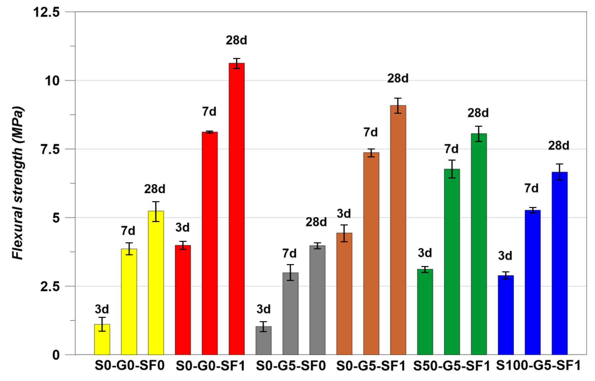
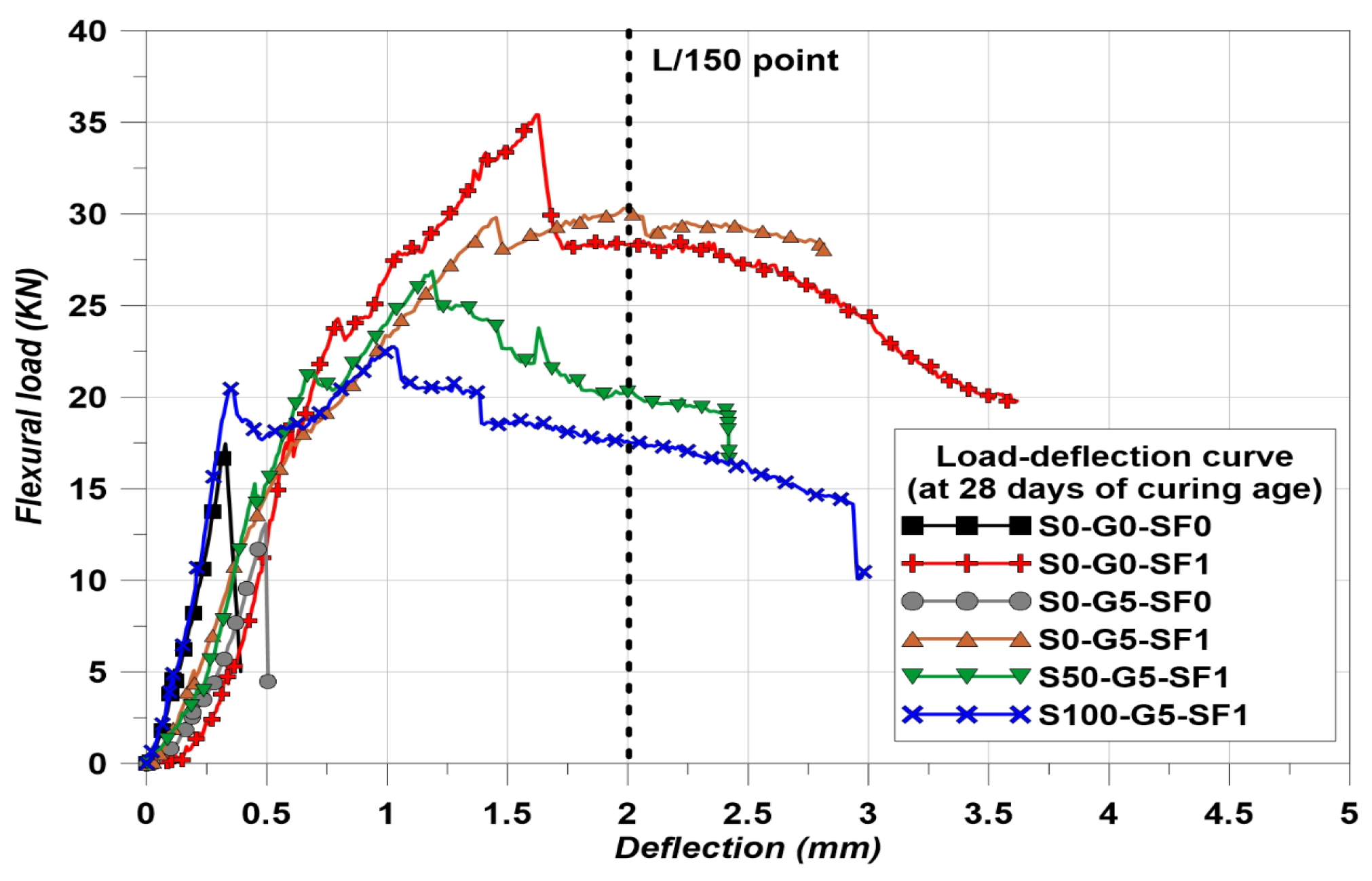
The flexural strength results are indicated in Figure 10 and the load–deflection curves of the specimens at 28 days of curing are indicated in Figure 11. The trend of flexural strength is similar to the compressive strength results, except for S0-G5-SF0 and S100-G5-SF1. In the case of the compressive strength, S100-G5-SF1 showed the lowest value. However, the lowest flexural strength was found for S0-G5-SF0. This is considered to have happened as a result of the inclusion of steel fiber. In addition, the arched type of steel fiber was used in this study; the anchorage effect of the arched type steel fiber helped to improve the flexural strength [46].
The for each specimen was calculated and the results are indicated in Table 8. The S0-G0-SF0 and S0-G5-SF0 could not measure the because these specimens were not used the steel fiber (brittle condition). The is based on the area of the load–deflection curve, the results of Table 8 demonstrate well the flexural performance after cracking.
3.3. Dry Density Results
Thermal conductivity is sensitive to the porosity of materials [47] and the porosity is related to the water absorption [48]. It can be considered that there are many voids when the water absorption rate is large [47,48]. Table 9 indicates the water absorption and dry density. The results of three specimens were averaged in each case.
S0-G5-SF1 showed the highest value of water absorption. This is because using fibers in concrete makes microcracks between cement matrix and the fibers [49]. In addition, graphite is also making concrete porous [15]. The combination of these phenomena, causing the water absorption of S0-G5-SF1, was measured as in in Table 9. Comparing the results of S0-G0-SF1, S0-G5-SF0, and S0-G5-SF1, this trend was reflected in the results of the thermal conductivity.
3.4. Thermal Conductivity Results
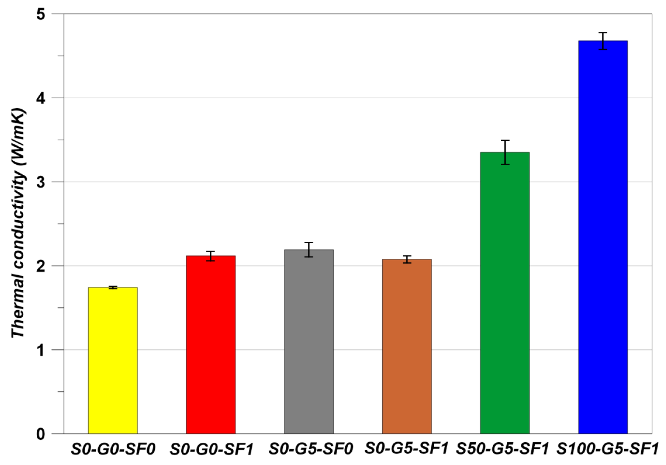
The thermal conductivity results are indicated in Figure 12. The S0-G5-SF0 showed a higher thermal conductivity than S0-G0-SF0 despite the negative effects of the graphite on the mechanical properties. As the graphite has high thermal conductivity, the thermal conductivity of S0-G5-SF0 appeared as in Figure 12 [15,16,17]. Steel fiber has also high thermal conductivity, so the S0-G0-SF1 showed almost the same thermal conductivity results as the S0-G5-SF0 specimens [28]. However, S0-G5-SF1 showed a slight decrease in thermal conductivity and this phenomenon is related to the water absorption rate in discussed in Section 3.3. The water absorption rate showed the highest value when using the steel fiber and graphite simultaneously. Therefore, the thermal conductivity of S0-G5-SF1 showed a slight decreasing behavior.
In S50-G5-SF1 and S100-G5-SF1, the thermal conductivity was increased to a large gap in comparison to other specimens. In the aspect of concrete volume, the fine aggregate occupies 30% of concrete volume [19]. S50-G5-SF1 was substituted in the fine aggregate with 50% of SiC (occupying 15% of concrete volume) and S100-G5-SF1 was substituted with the fine aggregate up to 100% of SiC (occupying 30% of concrete volume). Therefore, the thermal conductivity was affected by SiC much more than the S0-G0-SF1, S0-G5-SF0, and S0-G5-SF1 specimens [45].
3.5. Freeze–Thaw Test Results
The results of RDM are indicated in Figure 13 and the mass loss results are indicated in Figure 14. S0-G5-SF0 was terminated in the FT test at 120 cycles. The mass loss of S0-G5-SF0 was accelerated after 30 cycles of the FT test. Due to the poor mechanical properties of using graphite, the FT test of S0-G5-SF0 was terminated at an early state [50]. On the other hand, the specimens which used the steel fiber showed an improvement of FT resistance. Compared to S0-G5-SF0 and S0-G5-SF1, S0-G5-SF1 maintained an RDM of above 60% for 150 cycles, and the mass loss was decreased. In addition, compared to S0-G0-SF0 and S0-G0-SF1, S0-G0-SF1 showed a marginal ability to resist the FT cycles. However, the S0-G0-SF0 showed the RDM as being under 60% at 300 cycles. These results show that the steel fiber improved mechanical performance and thermal conductivity and improved the FT resistance [25,51].
Using SiC has many benefits for concrete such as improving the durability of the cement composites via a filler effect and improving the thermal attack resistance. Although using 100% of SiC as a fine aggregate led to a decrease in mechanical properties [45], the benefits of using SiC could be confirmed when using the SiC up to 50% [45]. Comparing S0-G5-SF1 and S50-G5-SF1, the FT resistance of S50-G5-SF1 was dramatically improved. S50-G5-SF1 showed above 60% of RDM at the last cycle and the mass loss was reduced compared to S0-G5-SF1. S100-G5-SF1 showed relatively poorer FT resistance than S50-G5-SF1. Fully substituting the fine aggregate for SiC may help to improve the thermal conductivity; however, there were many disadvantages to other performances such as compressive and flexural strength. Usually, monotonous PSD brings about a reduction in the concrete performance and SiC has monotonous PSD (see Figure 2) [45]. Therefore, 50% of SiC and steel fiber compensated the negative effect from the graphite and the combination of SiC and steel fiber improved the FT resistance significantly.
3.6. Rapid Cyclic Thermal Attack Results
The effect of RCTA was observed by comparing the compressive strength. The results are indicated in Table 10. The trend of RCTA results appeared similar to the FT test. However, the range of the temperature cycle was much harsher than the FT test. Therefore, the degradation of the compressive strength appeared remarkable. S0-G5-SF0 showed the largest reduction ratio. Comprehensively, the specimen case using only graphite showed the decreasing the performance of concrete except for thermal conductivity. S0-G0-SF1 showed the lowest reduction ratio. S0-G0-SF1 showed the best performance in this study. Using arched type steel fiber brings many benefits for the performance of the concrete. Arched type steel fiber could maximize the anchorage effect compared to other steel fibers because the arched type steel fiber anchored the whole body into the concrete matrix [46,52,53]. Therefore, it is considered that the RCTA result of S0-G0-SF1 was affected by this anchorage effect [46,52,53]. In addition, the compensation of the reduction ratio could be confirmed through S0-G5-SF1. The reduction ratio of S0-G5-SF0 was 44.96% and S0-G5-SF1 was 30.17%. Therefore, 14.79% of the reduction ratio was compensated.
SiC also improves the thermal attack resistance [29]. S50-G5-SF1 and S100-G5-SF1 showed that the reduction ratio by RCTA was decreased by 7.38% and 1.36%, respectively, compared to S0-G5-SF1. In particular, although S100-G5-SF1 showed poor mechanical properties, RCTA resisting performance was increased by using SiC compared to S0-G0-SF0 and S0-G5-SF1 [29].
4. Conclusions
This study focused on the effect of thermal conductive materials on the FT resistance of concrete. The effect of thermal conductive materials on concrete was confirmed by various experiments. The comprehensive conclusions of this study are as follows:
- Arched type steel fiber improves the mechanical properties of concrete due to the anchorage effect. On the contrary, it was demonstrated that using graphite brought about a negative effect on the mechanical properties. However, graphite is a good material for improving the thermal conductivity of concrete. Therefore, the decrease in mechanical properties caused by using graphite could be compensated by using arched type steel fiber.
- SiC is able to be used as fine aggregate and has sufficient thermal conductivity. In addition, it was demonstrated that the steel fiber could be used as a thermal conductive material through the thermal conductivity results. The combination of SiC and steel fiber maximized the improvement in the thermal conductivity of concrete. Adding graphite also brought about an increase in thermal conductivity.
- It was demonstrated that using graphite is not suitable for FT and RCTA resistance through the results of the FT test and RCTA test. However, the arched type steel fiber showed a remarkable improvement of the FT resistance and RCTA. In addition, SiC compensated for the negative effect of graphite on the FT and RCTA.
Author Contributions
J.-S.R. conceptualized this paper; D.-H.Y. and B.-H.W. and J.-B.L. designed the experiment; D.-H.Y. and B.-H.W. performed the experiment; J.-B.L. and H.-G.K. analyzed data; S.-S.K. and J.-S.R. visualized data; S.-S.K. supervised this study; H.-G.K. corresponded this paper; B.-H.W. wrote this paper. All authors have read and agreed to the published version of the manuscript.
Funding
This research received no external funding.
Institutional Review Board Statement
Not applicable.
Informed Consent Statement
Not applicable.
Data Availability Statement
Not applicable.
Acknowledgments
This work was supported by the Korea Institute of Energy Technology Evaluation and Planning (KETEP) and the Ministry of Trade, Industry and Energy (MOTIE) of the Republic of Korea (No. 20183010025510).
Conflicts of Interest
The authors declare no conflict of interest.
References
- Chen, J.; Jahanian, M.; Ramakrishnan, K. Black ice! using information centric networks for timely vehicular safety information dissemination. In Proceedings of the 2017 IEEE International Symposium on Local and Metropolitan Area Networks (LANMAN), Osaka, Japan, 12–14 June 2017; pp. 1–6. [Google Scholar]
- Wang, K.; Nelsen, D.E.; Nixon, W.A. Damaging effects of deicing chemicals on concrete materials. Cem. Concr. Compos. 2006, 28, 173–188. [Google Scholar] [CrossRef]
- Seo, T.; Jung, Y.; Kim, J.; Na, O. Durability of steam-cured concrete with slag under the combined deterioration of freeze-thaw cycles and de-icing chemicals. Struct. Concr. 2017, 18, 75–83. [Google Scholar] [CrossRef]
- Matalkah, F.; Soroushian, P. Freeze thaw and deicer salt scaling resistance of concrete prepared with alkali aluminosilicate cement. Constr. Build. Mater. 2018, 163, 200–213. [Google Scholar] [CrossRef]
- Zhao, H.-M.; Wang, S.-G.; Wu, Z.-M.; Che, G.-J. Concrete slab installed with carbon fiber heating wire for bridge deck deicing. J. Transp. Eng. 2010, 136, 500–509. [Google Scholar] [CrossRef]
- Liu, X.; Rees, S.J.; Spitler, J.D. Modeling snow melting on heated pavement surfaces. Part II: Experimental validation. Appl. Therm. Eng. 2007, 27, 1125–1131. [Google Scholar] [CrossRef]
- Liu, Y.; Lai, Y.; Ma, D. Research of carbon fibre grille reinforced composites in airport pavement snowmelt. Mater. Res. Innov. 2015, 19, S10–49. [Google Scholar] [CrossRef]
- Liew, K.; Kai, M.; Zhang, L. Carbon nanotube reinforced cementitious composites: An overview. Compos. Part A Appl. Sci. Manuf. 2016, 91, 301–323. [Google Scholar] [CrossRef]
- Chang, C.; Ho, M.; Song, G.; Mo, Y.-L.; Li, H. A feasibility study of self-heating concrete utilizing carbon nanofiber heating elements. Smart Mater. Struct. 2009, 18, 127001. [Google Scholar] [CrossRef]
- Kim, G.; Naeem, F.; Kim, H.; Lee, H.-K. Heating and heat-dependent mechanical characteristics of CNT-embedded cementitious composites. Compos. Struct. 2016, 136, 162–170. [Google Scholar] [CrossRef]
- Lee, H.; Kang, D.; Song, Y.M.; Chung, W. Heating experiment of CNT cementitious composites with single-walled and multiwalled carbon nanotubes. J. Nanomater. 2017, 2017. [Google Scholar] [CrossRef] [Green Version]
- Manzur, T.; Yazdani, N.; Emon, M.; Bashar, A. Potential of carbon nanotube reinforced cement composites as concrete repair material. J. Nanomater. 2016, 2016. [Google Scholar] [CrossRef] [Green Version]
- Gomis, J.; Galao, O.; Gomis, V.; Zornoza, E.; Garcés, P. Self-heating and deicing conductive cement. Experimental study and modeling. Constr. Build. Mater. 2015, 75, 442–449. [Google Scholar] [CrossRef]
- Frąc, M.; Pichór, W.; Szołdra, P. Cement composites with expanded graphite as resistance heating elements. J. Compos. Mater. 2020, 54, 3821–3831. [Google Scholar] [CrossRef]
- Wei, J.; Zhao, L.; Zhang, Q.; Nie, Z.; Hao, L. Enhanced thermoelectric properties of cement-based composites with expanded graphite for climate adaptation and large-scale energy harvesting. Energy Build. 2018, 159, 66–74. [Google Scholar] [CrossRef]
- Yuan, H.-W.; Lu, C.-H.; Xu, Z.-Z.; Ni, Y.-R.; Lan, X.-H. Mechanical and thermal properties of cement composite graphite for solar thermal storage materials. Sol. Energy 2012, 86, 3227–3233. [Google Scholar] [CrossRef]
- Liu, S.; Wu, M.; Rao, M.; Li, L.; Xiao, H. Preparation, Properties, and Microstructure of Graphite Powder-Containing Conductive Concrete. Strength Mater. 2019, 51, 76–84. [Google Scholar] [CrossRef]
- Wu, S.P.; Wang, P.; Li, B.; Pang, L.; Guo, F. Study on mechanical and thermal properties of graphite modified cement concrete. In Key Engineering Materials; Trans Tech Publications Ltd.: Stafa-Zurich, Switzerland, 2014; pp. 84–88. [Google Scholar]
- Pedreros, L.; Cárdenas, F.; Ramírez, N.; Forero, E. NDT non-destructive test for quality evaluation of concrete specimens by ultrasonic pulse velocity measurement. In Proceedings of the IOP Conference Series: Materials Science and Engineering, Cartagena, Colombia, 30 October–1 November 2019; p. 012041. [Google Scholar]
- Kim, H.G.; Qudoos, A.; Jeon, I.K.; Woo, B.H.; Ryou, J.S. Assessment of PCM/SiC-based composite aggregate in concrete: Energy storage performance. Constr. Build. Mater. 2020, 258, 119637. [Google Scholar] [CrossRef]
- Zywietz, A.; Karch, K.; Bechstedt, F. Influence of polytypism on thermal properties of silicon carbide. Phys. Rev. B 1996, 54, 1791. [Google Scholar] [CrossRef]
- Jeon, I.K.; Qudoos, A.; Jakhrani, S.H.; Kim, H.G.; Ryou, J.-S. Investigation of sulfuric acid attack upon cement mortars containing silicon carbide powder. Powder Technol. 2020, 359, 181–189. [Google Scholar] [CrossRef]
- Zhao, M.; Zhang, X.; Song, W.; Li, C.; Zhao, S. Development of steel fiber-reinforced expanded-shale lightweight concrete with high freeze-thaw resistance. Adv. Mater. Sci. Eng. 2018, 2018. [Google Scholar] [CrossRef] [Green Version]
- Zhang, P.; Li, Q.; Chen, Y.; Shi, Y.; Ling, Y.-F. Durability of steel fiber-reinforced concrete containing SiO2 nano-particles. Materials 2019, 12, 2184. [Google Scholar] [CrossRef] [Green Version]
- Alsaif, A.; Bernal, S.A.; Guadagnini, M.; Pilakoutas, K. Freeze-thaw resistance of steel fibre reinforced rubberised concrete. Constr. Build. Mater. 2019, 195, 450–458. [Google Scholar] [CrossRef]
- Wang, J.; Dai, Q.; Si, R.; Ma, Y.; Guo, S. Fresh and mechanical performance and freeze-thaw durability of steel fiber-reinforced rubber self-compacting concrete (SRSCC). J. Clean. Prod. 2020, 277, 123180. [Google Scholar] [CrossRef]
- Niu, D.; Jiang, L.; Bai, M.; Miao, Y. Study of the performance of steel fiber reinforced concrete to water and salt freezing condition. Mater. Des. 2013, 44, 267–273. [Google Scholar] [CrossRef]
- Rao, R.; Fu, J.; Chan, Y.; Tuan, C.Y.; Liu, C. Steel fiber confined graphite concrete for pavement deicing. Compos. Part B Eng. 2018, 155, 187–196. [Google Scholar] [CrossRef]
- Pundienė, I.; Korjakins, A.; Pranckevičienė, J.; Kligys, M. Effect of silicon carbide aggregate, prepared by different methods, on the properties of refractory concrete with cenospheres. Ceram. Int. 2018, 44, 15944–15953. [Google Scholar] [CrossRef]
- ASTM. C150/C150M-17, Standard Specification for Portland Cement; American Society for Testing Materials: West Conshohocken, PA, USA, 2017. [Google Scholar]
- ASTM. C33, Standard Specification for Concrete Aggregates; American Society for Testing Materials: Philadelphia, PA, USA, 2003. [Google Scholar]
- Tanesi, J.; Meininger, R. Freeze-thaw resistance of concrete with marginal air content. Transp. Res. Rec. 2007, 2020, 61–66. [Google Scholar] [CrossRef] [Green Version]
- ASTM. C39/C39M, Standard Test Method for Compressive Strength of Cylindrical Test Specimens; ASTM Standards: West Conshohocken, PA, USA, 2005. [Google Scholar]
- ASTM. C469/C469M-14, Standard Test Method for Static Modulus of Elasticity and Poisson’s Ratio of Concrete in Compression; American Society for Testing and Materials: West Conshohocken, PA, USA, 2014. [Google Scholar]
- ASTM. C1609/C1609M-19, Standard Test Method for Flexural Performance of Fiber-Reinforced Concrete (Using Beam With Third-Point Loading); American Society for Testing Materials: West Conshohocken, PA, USA, 2019. [Google Scholar]
- ASTM. C948-81, Standard Test Method for Dry and Wet Bulk Density, Water Absorption, and Apparent Porosity of Thin Sections of Glass-Fiber Reinforced Concrete; American Society for Testing and Materials: West Conshohocken, PA, USA, 2009. [Google Scholar]
- Asadi, I.; Shafigh, P.; Hassan, Z.F.B.A.; Mahyuddin, N.B. Thermal conductivity of concrete–A review. J. Build. Eng. 2018, 20, 81–93. [Google Scholar] [CrossRef]
- Jittabut, P.; Chindaprasirt, P.; Pinitsoontorn, S. Experimental and Modeling Studies on Thermal Conductivity of Cement Composites Containing Nanosilica. In Advanced Materials Research; Trans Tech Publications Ltd.: Stafa-Zurich, Switzerland, 2014; pp. 119–123. [Google Scholar]
- Majewski, Ł.; Jaskulski, R.; Kubissa, W. Influence of partial replacement of sand with copper slag on the thermal properties of hardened concrete. In Proceedings of the 13th International Conference—Modern Building Materials, Structures and Techniques, VGTU, Vilnius, Lithuania, 16–17 May 2019. [Google Scholar]
- Shi, J.; Liu, Y.; Liu, B.; Han, D. Temperature effect on the thermal conductivity of expanded polystyrene foamed concrete: Experimental investigation and model correction. Adv. Mater. Sci. Eng. 2019, 2019. [Google Scholar] [CrossRef] [Green Version]
- ASTM. C666/C666M-03: Standard Test Method for Resistance of Concrete to Rapid Freezing and Thawing; ASTM: West Conshohocken, PA, USA, 2003. [Google Scholar]
- Zhang, J.; Yan, C.W.; Jia, J.Q. Compressive strength and splitting tensile strength of steel fiber reinforced ultra high strength concrete (SFRC). In Applied Mechanics and Materials; Trans Tech Publications Ltd.: Stafa-Zurich, Switzerland, 2010; pp. 1441–1444. [Google Scholar]
- Larsen, I.L.; Thorstensen, R.T. The influence of steel fibres on compressive and tensile strength of ultra high performance concrete: A review. Constr. Build. Mater. 2020, 256, 119459. [Google Scholar] [CrossRef]
- Zheng, Y.; Wu, X.; He, G.; Shang, Q.; Xu, J.; Sun, Y. Mechanical properties of steel fiber-reinforced concrete by vibratory mixing technology. Adv. Civ. Eng. 2018, 2018. [Google Scholar] [CrossRef] [Green Version]
- Woo, B.H.; Jeon, I.K.; Yoo, D.H.; Kim, H.G.; Ryou, J.-S. Ice-Melting Performance Assessment of Cement Composites Using Silicon Carbide as Fine Aggregate. Appl. Therm. Eng. 2021, 117113. [Google Scholar] [CrossRef]
- Won, J.-P.; Lee, J.-H.; Lee, S.-J. Flexural behaviour of arch-type steel fibre reinforced cementitious composites. Compos. Struct. 2015, 134, 565–571. [Google Scholar] [CrossRef]
- Chen, J.; Wang, H.; Xie, P.; Najm, H. Analysis of thermal conductivity of porous concrete using laboratory measurements and microstructure models. Constr. Build. Mater. 2019, 218, 90–98. [Google Scholar] [CrossRef]
- Shabbar, R.; Nedwell, P.; Wu, Z. Porosity and Water Absorption of Aerated Concrete with Varying Aluminium Powder Content. Int. J. Eng. Technol. 2018, 10. [Google Scholar] [CrossRef] [Green Version]
- Hwang, J.P.; Kim, M.; Ann, K.Y. Porosity generation arising from steel fibre in concrete. Constr. Build. Mater. 2015, 94, 433–436. [Google Scholar] [CrossRef]
- Shang, H.-s.; Cao, W.-q.; Wang, B. Effect of fast freeze-thaw cycles on mechanical properties of ordinary-air-entrained concrete. Sci. World J. 2014, 2014. [Google Scholar] [CrossRef]
- Li, X.K.; Song, W.H.; Li, C.Y. A review on frost resistance of steel fiber reinforced lightweight aggregate concrete. In Applied Mechanics and Materials; Trans Tech Publications Ltd.: Stafa-Zurich, Switzerland, 2013; pp. 295–299. [Google Scholar]
- Won, J.-P.; Lee, J.-H.; Lee, S.-J. Bonding behaviour of arch-type steel fibres in a cementitious composite. Compos. Struct. 2015, 133, 117–123. [Google Scholar] [CrossRef]
- Won, J.-P.; Lee, J.-H.; Lee, S.-J. Predicting pull-out behaviour based on the bond mechanism of arch-type steel fibre in cementitious composite. Compos. Struct. 2015, 134, 633–644. [Google Scholar] [CrossRef]
Figure 1.
Used thermal conductive materials. (a) Arched-type steel fiber; (b) SiC; (c) Graphite.

Figure 2.
PSDs of the graphite, SiC, fine aggregate, and coarse aggregate.

Figure 3.
Specimen naming.

Figure 4.
The details of the research flow.

Figure 5.
The flexural behavior of the steel fiber reinforced concrete.

Figure 6.
Testing chamber and temperature cycle. (a) Freeze-thaw chamber; (b) One cycle of temperature.
Figure 6.
Testing chamber and temperature cycle. (a) Freeze-thaw chamber; (b) One cycle of temperature.

Figure 7.
RCTA test concept.

Figure 8.
Compressive strength results.

Figure 9.
Compressive stress–strain curves.

Figure 10.
Flexural strength results.

Figure 11.
Flexural load–deflection curves.

Figure 12.
Thermal conductivity.

Figure 13.
Freeze–thaw test results.

Figure 14.
Mass loss results.


Table 1.
Properties of OPC.
| Chemical Composition (%) | |||||
| SiO2 | Al2O3 | Fe2O3 | CaO | MgO | Other |
| 20.8 | 6.3 | 3.2 | 62 | 3.3 | 4.4 |
| Physical properties | |||||
| Blaine (cm2/g) | Specific gravity (ton/m3) | ||||
| 3200 | 3.15 | ||||
Table 2.
Properties of graphite.
| Chemical Composition (%) | Other Properties | ||
|---|---|---|---|
| C | Other | Specific Gravity (ton/m3) | Thermal Conductivity (W/mK) |
| 86% | 14% | 0.83 | 110 |
Table 3.
Properties of SiC.
| Chemical Composition (%) | |||
| SiC | Fe2O3 | Fe3C | Other |
| 94 | 0.7 | 0.5 | 4.8 |
| Other properties | |||
| Tensile strength (MPa) | Elastic modulus (GPa) | Specific gravity (ton/m3) | Thermal conductivity (W/mK) |
| 620 | 192 | 3.22 | 25.5–40 |
Table 4.
Properties of steel fiber.
| Tensile Strength (MPa) | Specific Gravity (ton/m3) | Aspect Ratio (%) | Thermal Conductivity (W/mK) |
|---|---|---|---|
| 1500 | 7.85 | 56 (Length: 42 mm, Diameter: 0.75 mm) | 57 |
Table 5.
Mixing properties of the specimens (unit: kg/m3).
| Specimen | W/C (%) | Water | Cement | Fine Agg | Coarse Agg | Water Reducer | SiC | Graphite | Steel Fiber |
|---|---|---|---|---|---|---|---|---|---|
| S0-G0-SF0 | 55 | 225.5 | 410 | 764 | 1032 | 4.1 | 0 | 8.26 | 0 |
| S0-G0-SF1 | 764 | 0 | 78.5 | ||||||
| S0-G5-SF0 | 764 | 0 | 0 | ||||||
| S0-G5-SF1 | 764 | 0 | 78.5 | ||||||
| S50-G5-SF1 | 382 | 382 | 78.5 | ||||||
| S100-G5-SF1 | 0 | 764 | 78.5 |
Table 6.
Air content results.
| Specimen | S0-G0-SF0 | S0-G0-SF1 | S0-G5-SF0 | S0-G5-SF1 | S50-G5-SF1 | S100-G5-SF1 |
|---|---|---|---|---|---|---|
| Air content (%) | 4.2 | 4.4 | 3.6 | 4.0 | 3.8 | 4.2 |
Table 7.
Results of the elastic modulus.
| Specimen | S0-G0-SF0 | S0-G0-SF1 | S0-G5-SF0 | S0-G5-SF1 | S50-G5-SF1 | S100-G5-SF1 |
|---|---|---|---|---|---|---|
| Elastic modulus (MPa) | 24,561 | 26,860 | 21,981 | 24,432 | 24,111 | 22,663 |
Table 8.
Results of the equivalent flexural strength.
| Specimen | S0-G0-SF0 | S0-G0-SF1 | S0-G5-SF0 | S0-G5-SF1 | S50-G5-SF1 | S100-G5-SF1 |
|---|---|---|---|---|---|---|
| Could not measure | 6.465 | Could not measure | 6.252 | 5.538 | 5.316 |
Table 9.
Results of the dry density and water absorption.
| Specimen | S0-G0-SF0 | S0-G0-SF1 | S0-G5-SF0 | S0-G5-SF1 | S50-G5-SF1 | S100-G5-SF1 |
|---|---|---|---|---|---|---|
| Water absorption (%) | 4.682 | 4.923 | 5.593 | 7.076 | 5.694 | 6.449 |
| Dry density (kg/m3) | 2098.24 | 2145.61 | 1967.79 | 2019.11 | 2110.11 | 2047.97 |
Table 10.
Results of RCTA.
| Specimen | S0-G0-SF0 | S0-G0-SF1 | S0-G5-SF0 | S0-G5-SF1 | S50-G5-SF1 | S100-G5-SF1 |
|---|---|---|---|---|---|---|
| Before RCTA (MPa) | 46.14 | 53.37 | 38.28 | 49.58 | 45.19 | 34.19 |
| After RCTA (MPa) | 30.82 | 45.81 | 21.07 | 34.62 | 34.89 | 24.34 |
| Reduction ratio (%) | 33.20 | 14.16 | 44.96 | 30.17 | 22.79 | 28.81 |
Publisher’s Note: MDPI stays neutral with regard to jurisdictional claims in published maps and institutional affiliations. |
© 2021 by the authors. Licensee MDPI, Basel, Switzerland. This article is an open access article distributed under the terms and conditions of the Creative Commons Attribution (CC BY) license (https://creativecommons.org/licenses/by/4.0/).
Share and Cite
MDPI and ACS Style
Woo, B.-H.; Yoo, D.-H.; Kim, S.-S.; Lee, J.-B.; Ryou, J.-S.; Kim, H.-G. Effects of Thermal Conductive Materials on the Freeze-Thaw Resistance of Concrete. Materials 2021, 14, 4063. https://doi.org/10.3390/ma14154063
AMA Style
Woo B-H, Yoo D-H, Kim S-S, Lee J-B, Ryou J-S, Kim H-G. Effects of Thermal Conductive Materials on the Freeze-Thaw Resistance of Concrete. Materials. 2021; 14(15):4063. https://doi.org/10.3390/ma14154063
Chicago/Turabian StyleWoo, Byeong-Hun, Dong-Ho Yoo, Seong-Soo Kim, Jeong-Bae Lee, Jae-Suk Ryou, and Hong-Gi Kim. 2021. "Effects of Thermal Conductive Materials on the Freeze-Thaw Resistance of Concrete" Materials 14, no. 15: 4063. https://doi.org/10.3390/ma14154063
Note that from the first issue of 2016, this journal uses article numbers instead of page numbers. See further details here.