
Towards Enhancing the Potential of Injection Molding Tools through Optimized Close-Contour Cooling and Additive Manufacturing


 ,
,
Abstract
:1. Introduction
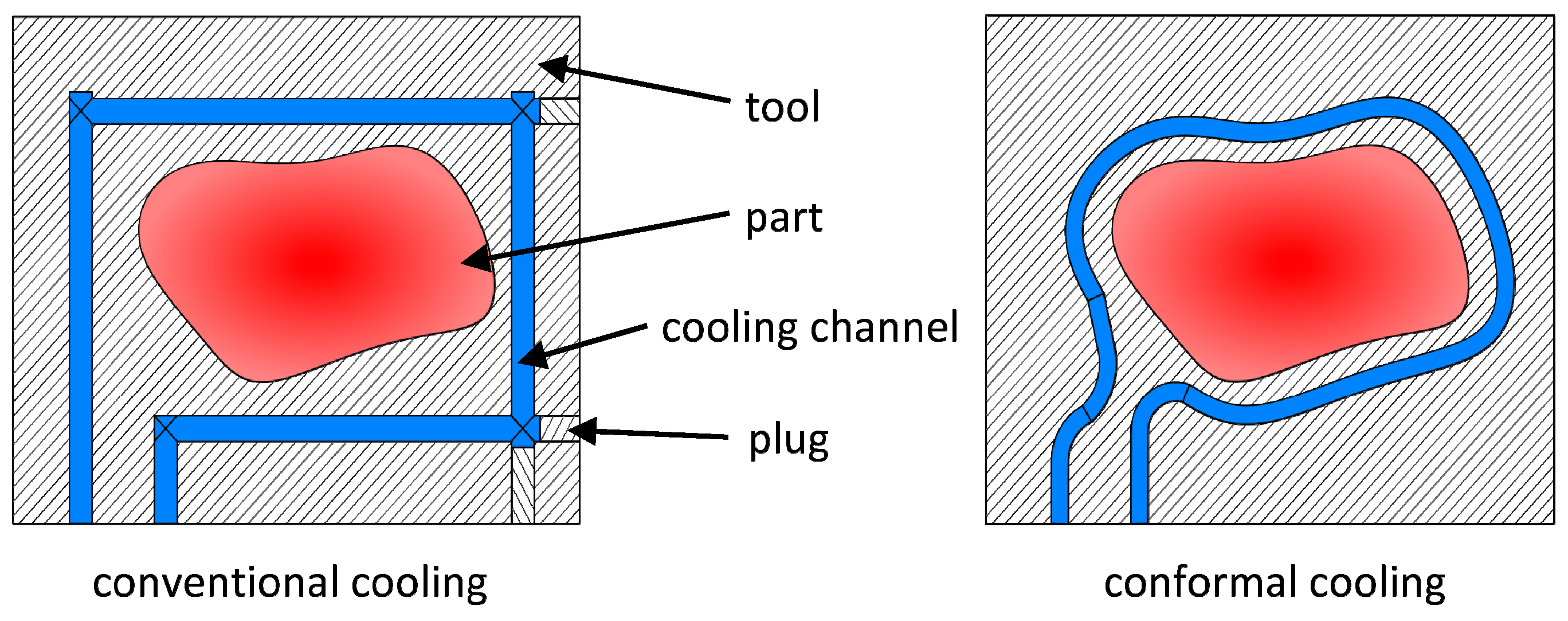
1.1. Cooling Systems of Injection Molding Tools for Thermoplastics
1.2. Cooling System Optimization
2. Methods
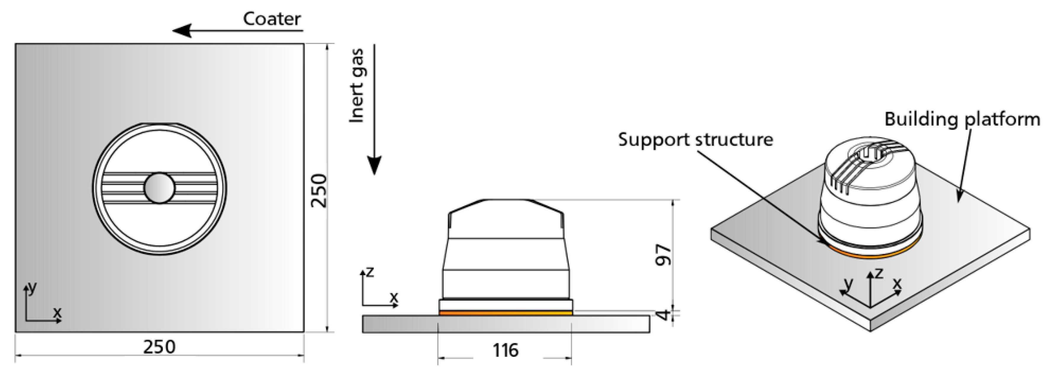
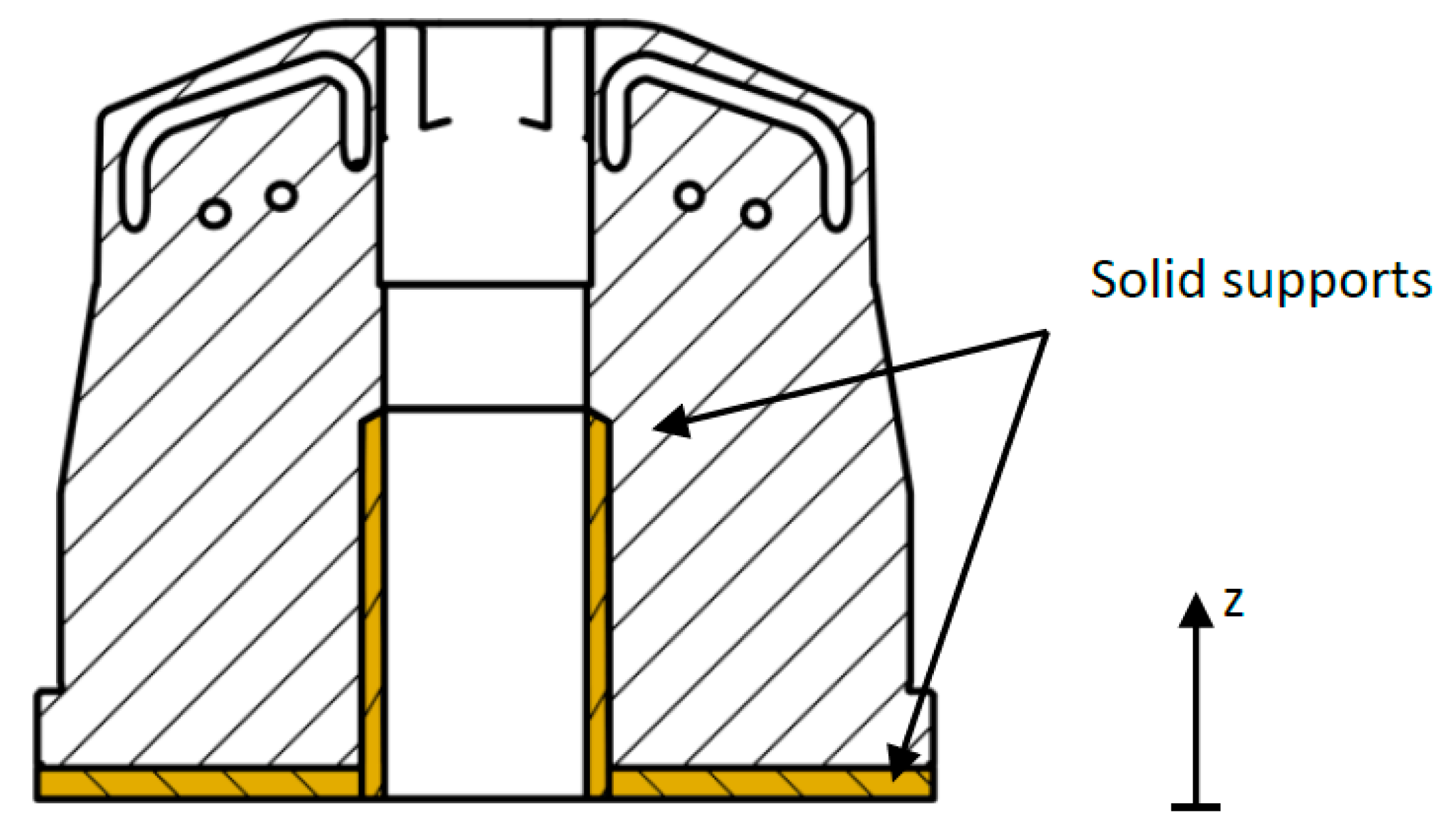
2.1. Reference Part and Initial Configuration
2.2. Non-Linear Optimization
2.2.1. Optimization of the Conventional Cooling System
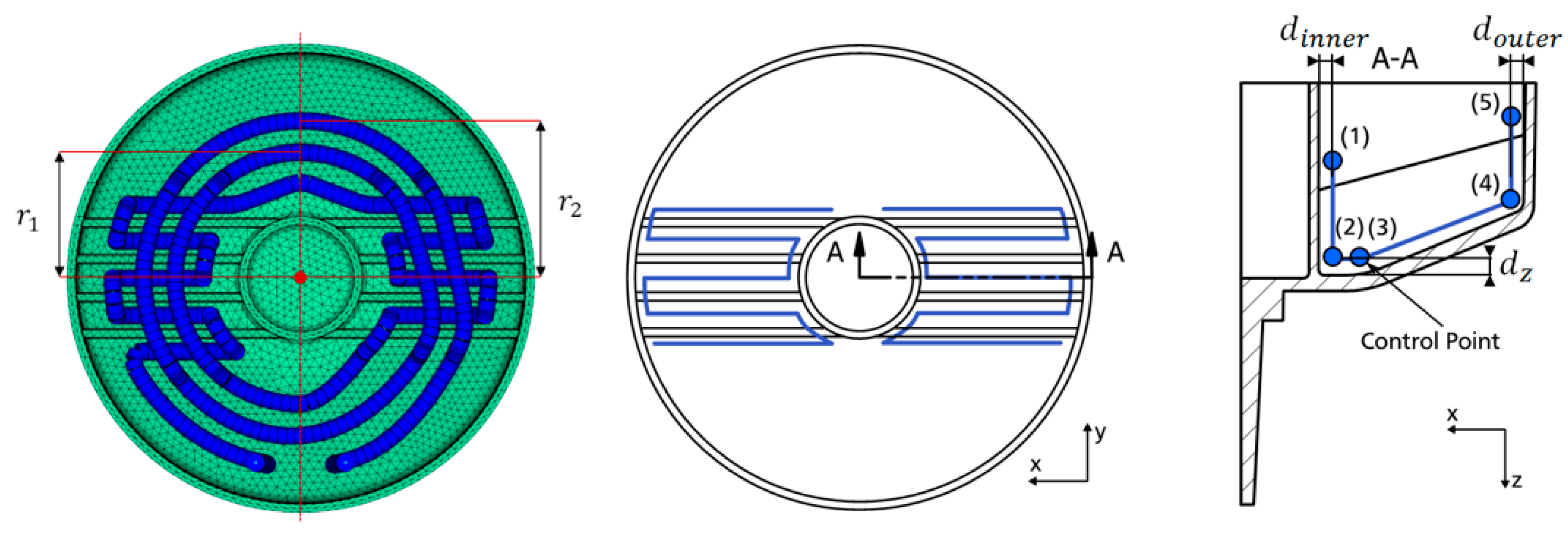
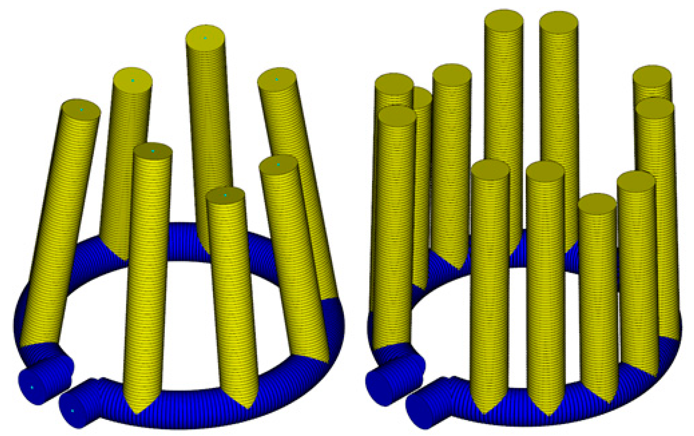
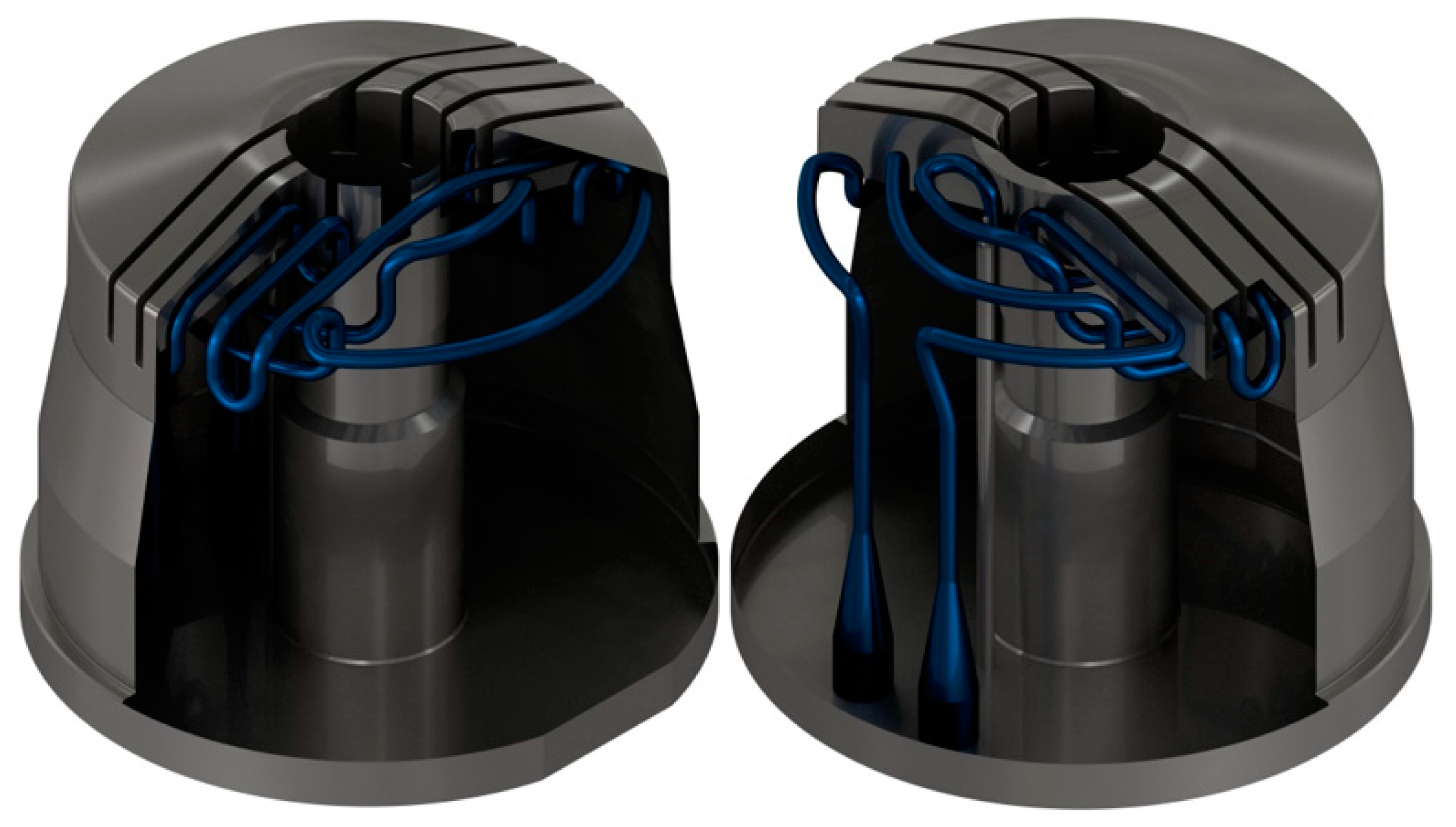
2.2.2. Optimization of a Close-Contour Cooling System
3. Results and Discussion
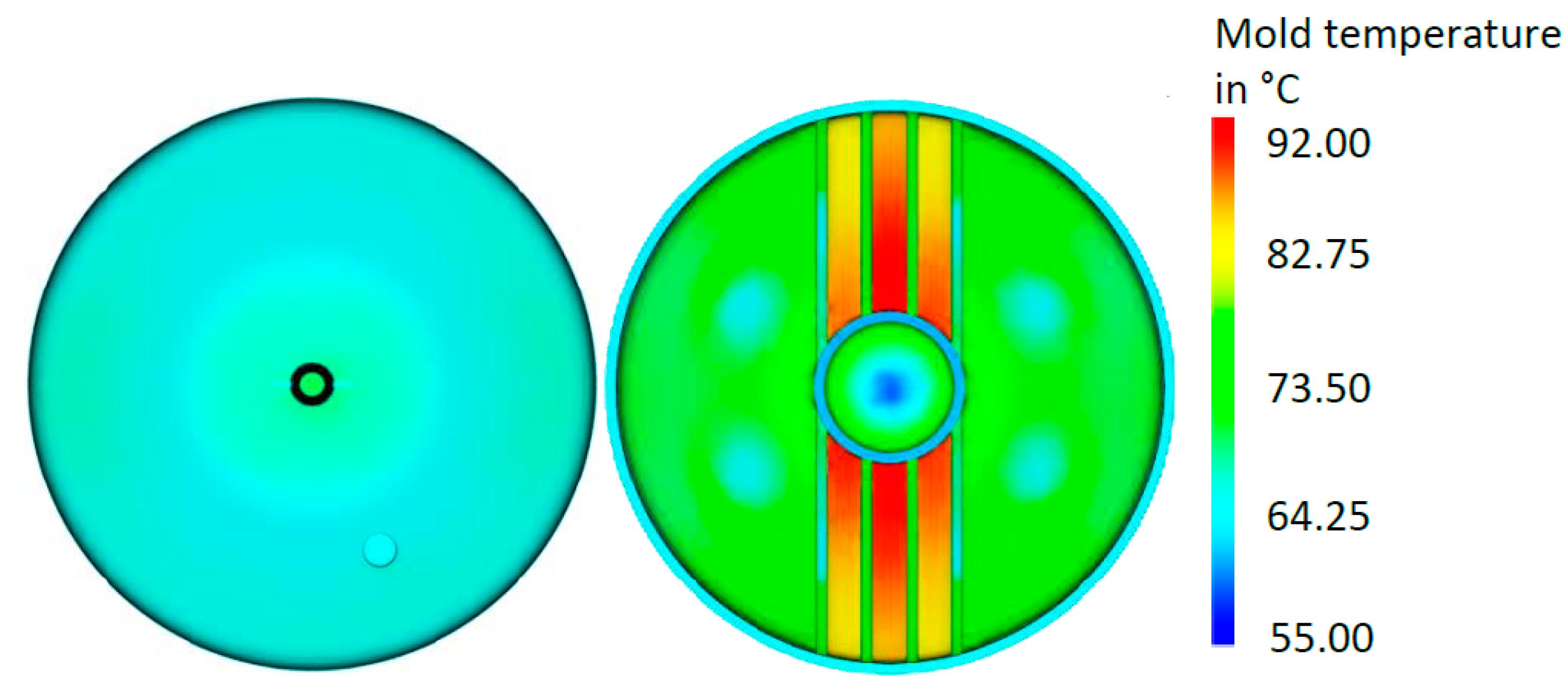
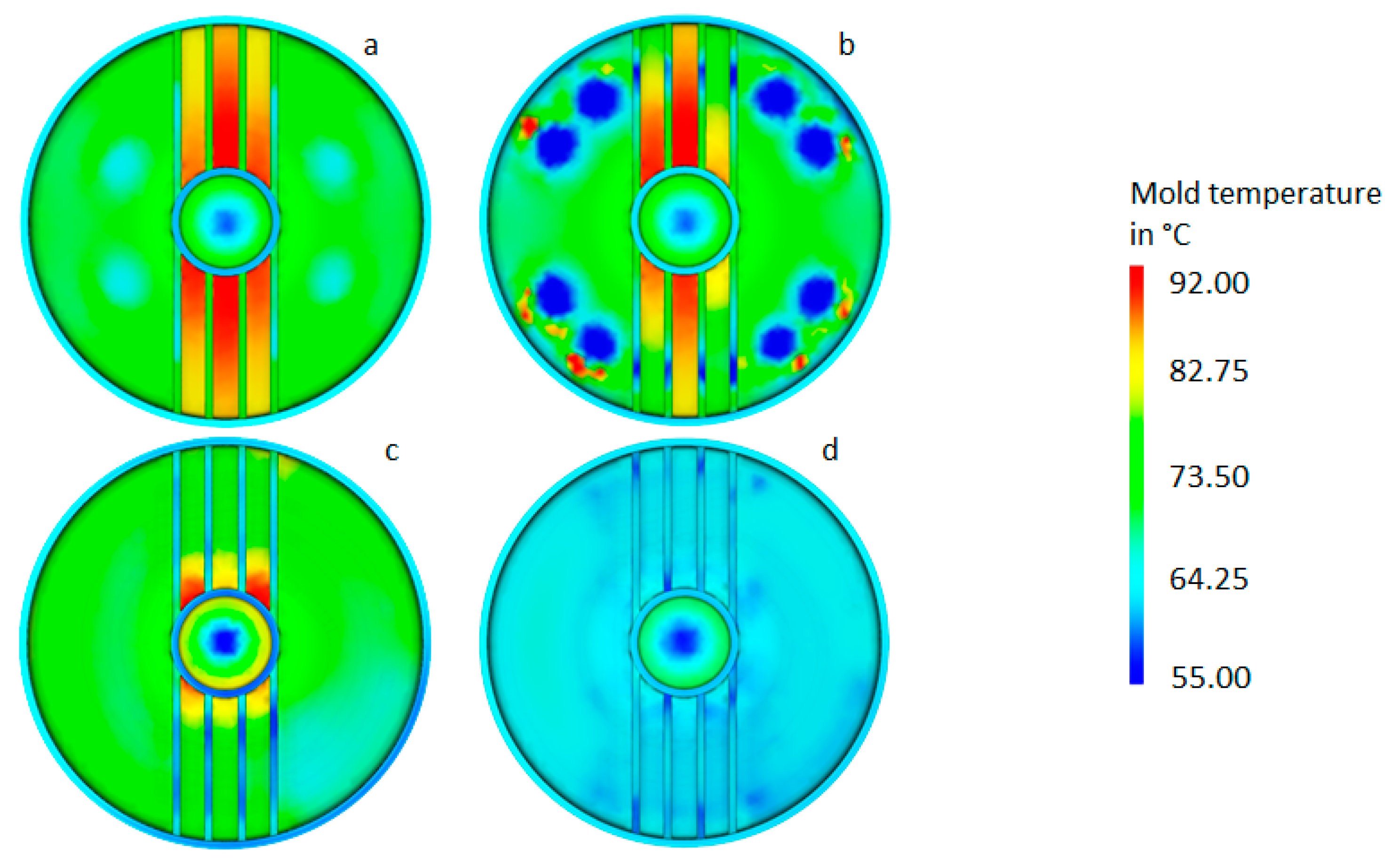
3.1. Initial Configuration
3.2. Optimized Conventional Cooling
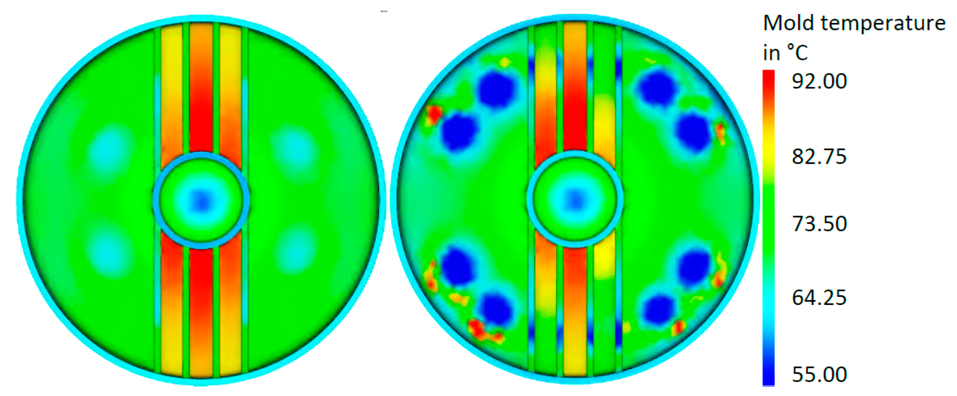
3.3. Optimized Close-Contour Cooling
3.4. Comparison of Results
3.5. Economic Consideration
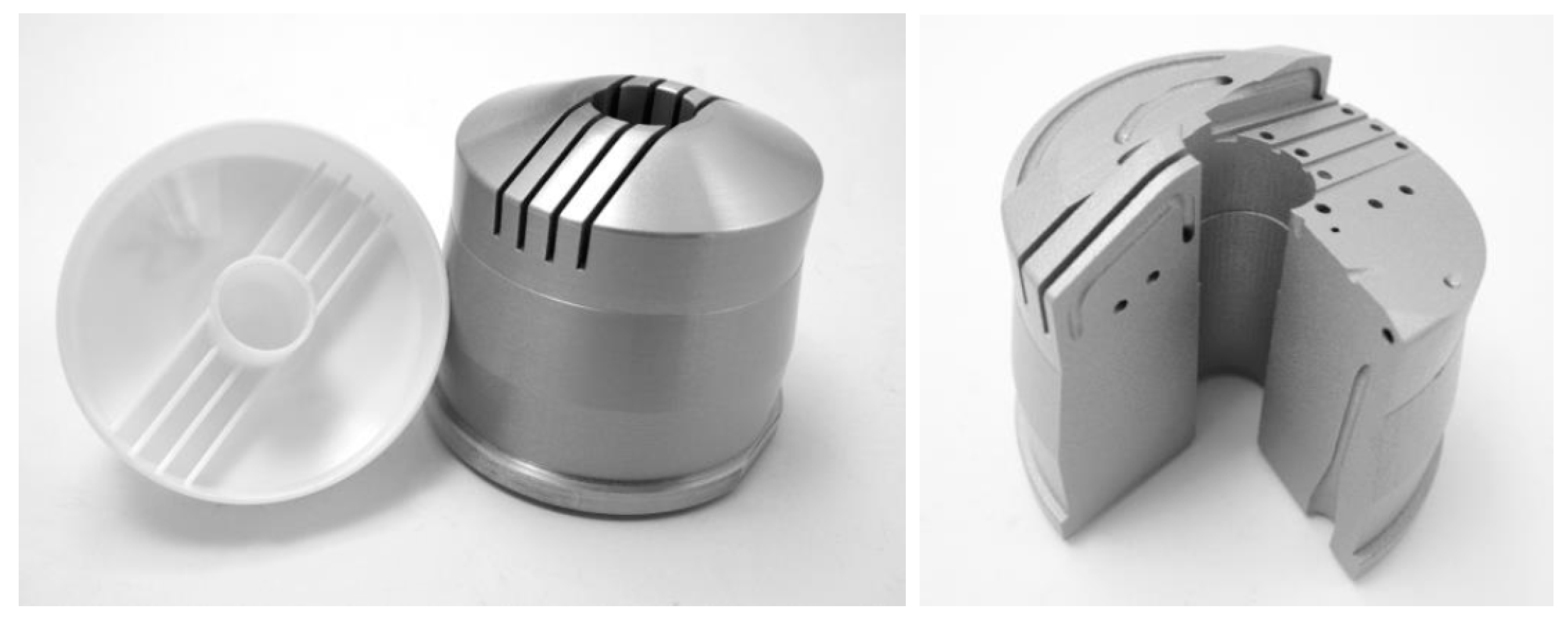
3.6. Proof of Concept Prototype Manufacturing
4. Summary and Conclusions
Author Contributions
Funding
Institutional Review Board Statement
Informed Consent Statement
Data Availability Statement
Acknowledgments
Conflicts of Interest
References
- Callister, W.D.; Rethwisch, D.G. Materials Science and Engineering, 9th ed.; John Wiley & Sons: Hoboken, NJ, USA, 2014. [Google Scholar]
- Agazzi, A.; Sobotka, V.; LeGoff, R.; Jarny, Y. Optimal cooling design in injection moulding process—A new approach based on morphological surfaces. J. Appl. Therm. Eng. 2013, 52, 170–178. [Google Scholar] [CrossRef]
- Dangel, R. Spritzgießwerkzeuge für Einsteiger, 2nd ed.; Carl Hanser Verlag GmbH & Co.: Munich, Germany, 2017. [Google Scholar]
- Hopmann, C.; Nikoleizig, P. Inverse thermal mold design for injection molds. Int. J. Mater. Form. 2016, 11, 113–124. [Google Scholar] [CrossRef]
- Zeyn, H. Industrialisierung der Additiven Fertigung. Digitalisierte Prozesskette—von der Entwicklung bis zum Einsetzbaren Artikel—Industrie 4.0; Beuth Verlag: Berlin, Germany, 2017. [Google Scholar]
- Kranz, J. Methodik und Richtlinien für die Konstruktion von Laseradditiv Gefertigten Leichtbaustrukturen; Springer: Berlin/Heidelberg, Germany, 2017. [Google Scholar]
- Richard, H.A.; Schramm, B.; Zipsner, T. Additive Fertigung von Bauteilen und Strukturen; Springer: Wiesbaden, Germany, 2017. [Google Scholar]
- Schmidt, T. Potentialbewertung Generativer Fertigungsverfahren für Leichtbauteile; Springer: Berlin/Heidelberg, Germany, 2016. [Google Scholar]
- Verein Deutscher Ingenieure. Handlungsfelder—Additive Fertigungsverfahren; Verein Deutscher Ingenieure: Düsseldorf, Germany, 2016. [Google Scholar]
- Park, H.S.; Dang, X.P. Development of a smart plastic injection mold with conformal cooling channels. J. Procedia Manuf. 2017, 10, 48–59. [Google Scholar] [CrossRef]
- Mazur, M.; Leary, M.; McMillan, M.; Elambasseril, J.; Brandt, M. SLM additive manufacture of H13 tool steel with conformal cooling and structural lattices. RPJ 2016, 22, 504–518. [Google Scholar] [CrossRef]
- Reis, N.C.; Vasco, J.C.; Barreiros, F.M. Conformal cooling by SLM to improve injection moulding. In Proceedings of the PMI 2018—Polymers and Moulds Innovations, Guimarães, Portugal, 19–21 September 2018. [Google Scholar]
- Brooks, H.; Brigden, K. Design of conformal cooling layers with self-supporting lattices for additively manufactured tooling. J. Addit. Manuf. 2016, 11, 16–22. [Google Scholar] [CrossRef] [Green Version]
- Hopmann, C.; Menges, G.; Michaeli, W.; Mohren, P. Spritzgießwerkzeuge; Carl Hanser Verlag GmbH & Co.: Munich, Germany, 2018. [Google Scholar]
- Li, Z.; Wang, X.; Gu, J.; Ruan, S.; Shen, C.; Lyu, Y.; Zhao, Y. Topology optimization for the design of conformal cooling system in thin-wall injection molding based on BEM. Int. J. Adv. Manuf. Technol. 2017, 94, 1041–1059. [Google Scholar] [CrossRef]
- Domschke, W.; Scholl, A. Heuristische Verfahren; Friedrich-Schiller-Universität Jena, Wirtschaftswissenschaftliche Fakultät: Jena, Germany, 2006. [Google Scholar]
- Wang, Y.; Yu, K.M.; Wang, C.C.; Zhang, Y. Automatic design of conformal cooling circuits for rapid tooling. J. CAD 2011, 43, 1001–1010. [Google Scholar] [CrossRef]
- Wang, Y.; Yu, K.M.; Wang, C.C. Spiral and conformal cooling in plastic injection molding. J. CAD 2015, 63, 1–11. [Google Scholar] [CrossRef]
- Myers, R.H.; Montgomery, D.C.; Anderson-Cook, C.M. Response Surface Methodology: Process and Product Optimization Using Designed Experiments; John Wiley & Sons: Hoboken, NJ, USA, 2009. [Google Scholar]
- Cavazzuti, M. Optimization Methods; Springer: Berlin/Heidelberg, Germany, 2013. [Google Scholar]
- Nielen, S.; Willem, R.; Anirban, B.; Trent, E.; Tushar, G.; Ken, C. LS-OPT User’s Manual: A Design Optimization and Probabilistic Analysis Tool for the Engineering Analyst; Version. 5.2; Livermore Software Technology Corporation: Livermore, CA, USA, 2015. [Google Scholar]
- Siebertz, K.; Van Bebber, D.; Hochkirchen, T. Statistische Versuchsplanung, 2nd ed.; Springer: Berlin/Heidelberg, Germany, 2017. [Google Scholar]
- Snyman, J.A. The LFOPC leap-frog algorithm for constrained optimization. Comput. Math. Appl. 2000, 40, 1085–1096. [Google Scholar] [CrossRef] [Green Version]
- Snyman, J.A. An improved version of the original leap-frog dynamic method for unconstrained minimization: LFOP1(b). J. Appl. Math. Model. 1983, 7, 216–218. [Google Scholar] [CrossRef]
- Stander, N.; Craig, K.J. On the robustness of a simple domain reduction scheme for simulation-based optimization. Eng. Comput. 2002, 19, 431–450. [Google Scholar] [CrossRef] [Green Version]
- Wonisch, A.; Jakobi, R.; Ullrich, L.; Gries, S.; Jones, C.; Hennebicque, M. Fine Channels, Maximum Efficiency. Kunstst. Int. 2019, 9, 110–113. [Google Scholar]
- Pakkanen, J.; Calignano, F.; Trevisan, F.; Lorusso, M.; Ambrosio, E.P.; Manfredi, D.; Fino, P. Study of internal channel surface roughnesses manufactured by selective laser melting in aluminum and titanium alloys. Metall. Mater. Trans. A 2017, 47, 3837–3844. [Google Scholar] [CrossRef]
- Liu, C.; Cai, Z.; Dai, Y.; Huang, N.; Xu, F.; Lao, C. Experimental comparison of the ow rate and cooling performance of internal cooling channels fabricated via selective laser melting and conventional drilling process. Int. J. Adv. Manuf. Technol. 2018, 96, 2757–2767. [Google Scholar] [CrossRef]


| Property | Value | Unit |
|---|---|---|
| Injection time | 0.8 | s |
| Volume and pressure control | 99 | % |
| Holding-pressure phase duration | 10 | s |
| Holding pressure | 800 | bar |
| Molten mass temperature | 200 | °C |
| Cooling medium temperature | 60 | °C |
| Cooling medium flow rate | 10 | L/min |
| Tool mold opening time | 5 | s |
| Condition | Value |
|---|---|
| Temperature difference in cooling agent | <3 °C |
| Minimum cycle time reduction | 10% |
| Reduction of cavity temperature standard deviation | 10% |
| Quasi-static loading | 1000 bar |
| Design Variable | Description | Start Value | Range | Unit |
|---|---|---|---|---|
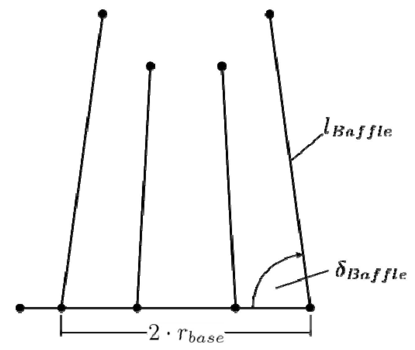
| nbaffle | Number of channels | 8 | 4–12 | - |
| rbase | Radius of the base channel | 40.8 | 30–45 | mm |
| lbaffle | Length of channels | 80.0 | 50–80 | mm |
| äbaffle | Channel angles | 81.0 | 78–90 | ° |
| Parameter | Description | Initial Value | Range | Unit |
|---|---|---|---|---|
| dinner | Distance to inner hollow cylinder | 10 | 3–15 | mm |
| douter | Distance to outer hollow cylinder | 10 | 3–15 | mm |
| dz | Distance to mold part in z-direction | 5 | 3–15 | mm |
| dchannel | Diameter of cooling channel | 4 | 3–5 | mm |
| r1 | Radius 1 | 25 | 20–30 | mm |
| r2 | Radius 2 | 35 | 25–40 | mm |
| Property | Value | Unit | |
|---|---|---|---|
| Cycle Time | 43.9 | s | |
| Cavity temperature | Mean value | 70.0 | °C |
| Minimum value | 55.9 | °C | |
| Maximum value | 92.1 | °C | |
| Standard deviation | 7.4 | °C | |
| Mold part temperature | Mean value | 74.2 | °C |
| Maximum value | 175.4 | °C | |
| Standard deviation | 12.7 | °C | |
| Property | Initial | Optimized | Unit | Deviation | |
|---|---|---|---|---|---|
| Cycle time | 43.9 | 42.9 | s | −2.3% | |
| Cavity temperature | Mean value | 70.0 | 68.7 | °C | −1.9% |
| Maximum value | 92.1 | 97.6 | °C | 6.0% | |
| Standard deviation | 7.4 | 7.4 | °C | −0.0% | |
| Parameter | Description | Initial | Optimized | Unit |
|---|---|---|---|---|
| dinner | Distance to inner hollow cylinder | 10 | 3.1 | mm |
| douter | Distance to outer hollow cylinder | 10 | 4.5 | mm |
| dz | Distance to mold part in z-direction | 5 | 3.1 | mm |
| dchannel | Diameter of cooling channel | 4 | 3.2 | mm |
| r1 | Radius 1 | 25 | 26.4 | mm |
| r2 | Radius 2 | 35 | 35.1 | mm |
| Configuration | Conventional Initial | Conventional Optimized | Close Contour Initial | Close Contour Optimized | Unit | |
|---|---|---|---|---|---|---|
| Cycle time | 43.9 | 42.9 | 38.9 | 37.2 | s | |
| Cavity temperature | Mean value | 70.0 | 68.7 | 66.3 | 63.5 | °C |
| Maximum value | 92.1 | 97.6 | 78.1 | 70.0 | °C | |
| Standard deviation | 7.4 | 7.4 | 2.9 | 1.7 | °C | |
| Cooling | Cycle Time | Parts per | Material Costs Per Year | Revenue Per Year | ||
|---|---|---|---|---|---|---|
| Day | Month | Year | ||||
| Conventional | 43.94 s | 1966 | 58,990 | 717,706 | 125,599 € | 233,254 € |
| Close-contour | 37.25 s | 2319 | 69,584 | 846,604 | 148,156 € | 275,146 € |
| Difference: +128,898 | Difference: +41,892 € | |||||
Publisher’s Note: MDPI stays neutral with regard to jurisdictional claims in published maps and institutional affiliations. |
© 2021 by the authors. Licensee MDPI, Basel, Switzerland. This article is an open access article distributed under the terms and conditions of the Creative Commons Attribution (CC BY) license (https://creativecommons.org/licenses/by/4.0/).
Share and Cite
Gries, S.; Meyer, G.; Wonisch, A.; Jakobi, R.; Mittelstedt, C. Towards Enhancing the Potential of Injection Molding Tools through Optimized Close-Contour Cooling and Additive Manufacturing. Materials 2021, 14, 3434. https://doi.org/10.3390/ma14123434
Gries S, Meyer G, Wonisch A, Jakobi R, Mittelstedt C. Towards Enhancing the Potential of Injection Molding Tools through Optimized Close-Contour Cooling and Additive Manufacturing. Materials. 2021; 14(12):3434. https://doi.org/10.3390/ma14123434
Chicago/Turabian StyleGries, Sebastian, Guillaume Meyer, Andreas Wonisch, Reinhard Jakobi, and Christian Mittelstedt. 2021. "Towards Enhancing the Potential of Injection Molding Tools through Optimized Close-Contour Cooling and Additive Manufacturing" Materials 14, no. 12: 3434. https://doi.org/10.3390/ma14123434