
Neural Network-Based Prediction Model to Investigate the Influence of Temperature and Moisture on Vibration Characteristics of Skew Laminated Composite Sandwich Plates

 , ,
, ,  ,
,  ,
, 
Abstract
:1. Introduction
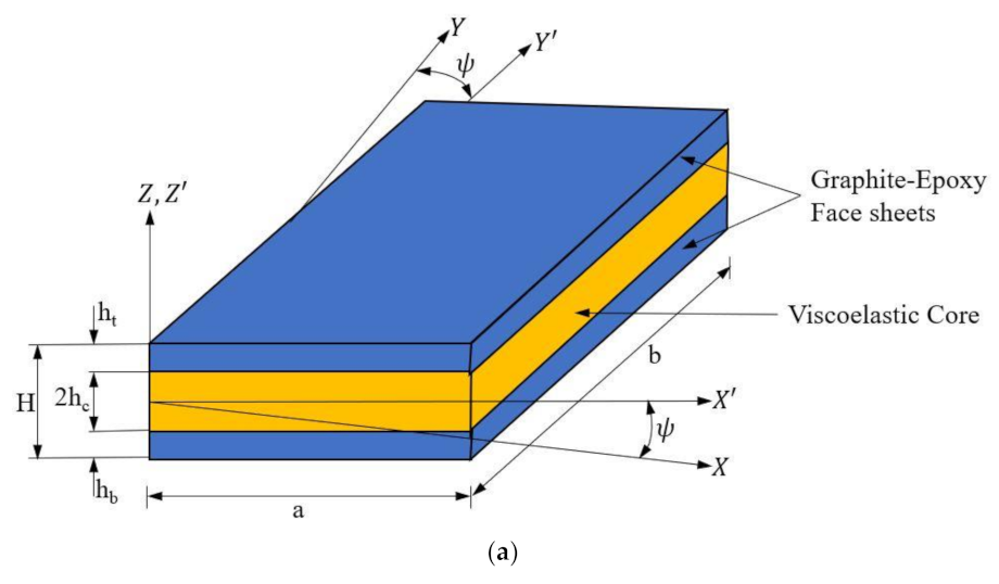
2. Mathematical Model
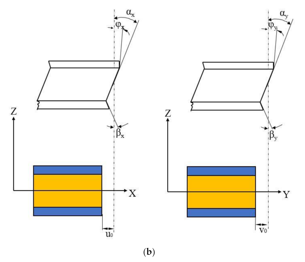
2.1. Linear Strain Displacement Relations
- εx, εy: Strains along x and y directions.
- εxy: In-plane shear strain.
- εxz, εyz: Transverse shear strains.
2.2. Non-Linear Strain Displacement Relations
2.3. Finite Element Model
2.4. Elemental Stiffness Matrix
2.5. Element Initial Stress Stiffness Matrix
- ex, ey, exy: Non-mechanical strains
- β1 and β2: Moisture coefficients
- α1 and α2: Thermal coefficients
- T and T0: Elevated and reference temperature
- C and C0: Elevated and reference moisture profiles.
2.6. Solution Process
3. Material Properties
4. Results and Discussions
4.1. Comparison with Previous Studies
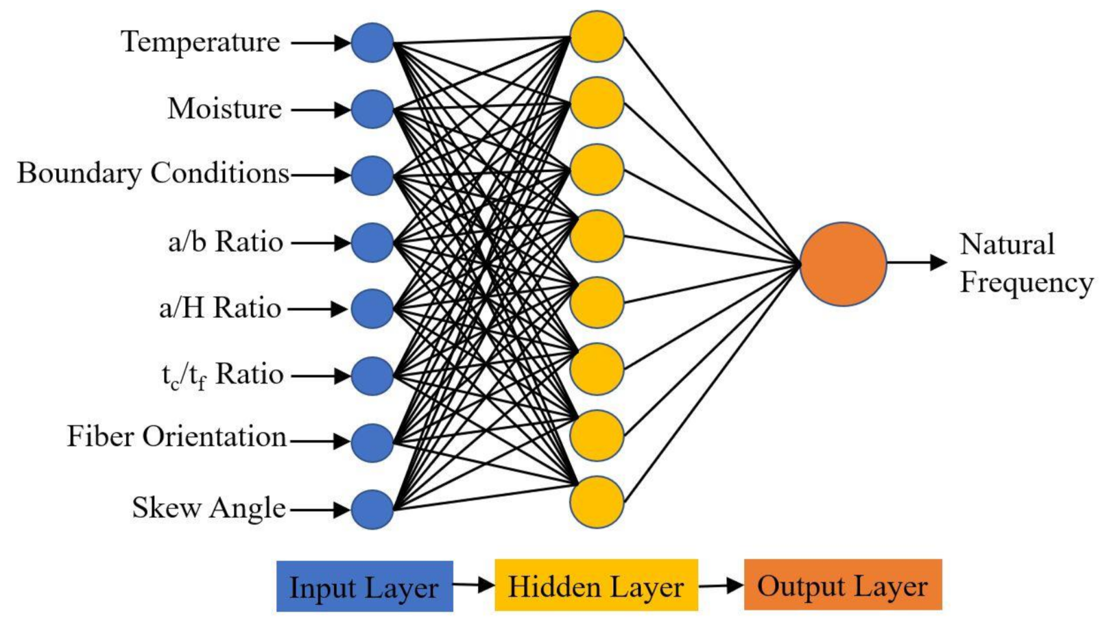
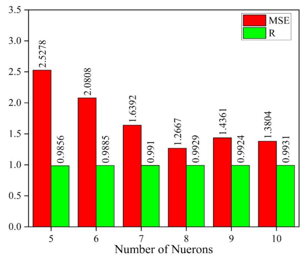
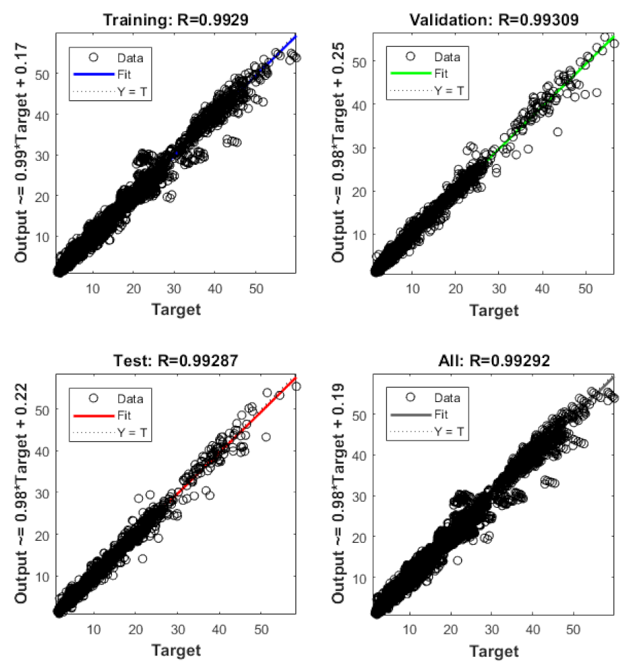
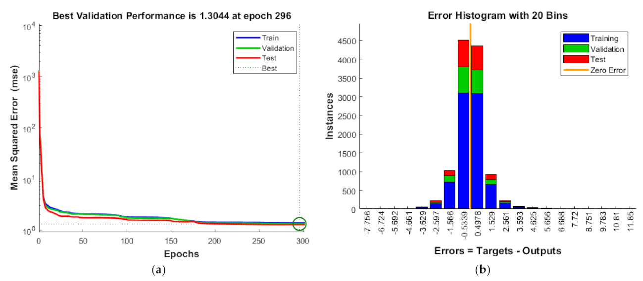
4.2. Artificial Neural Network
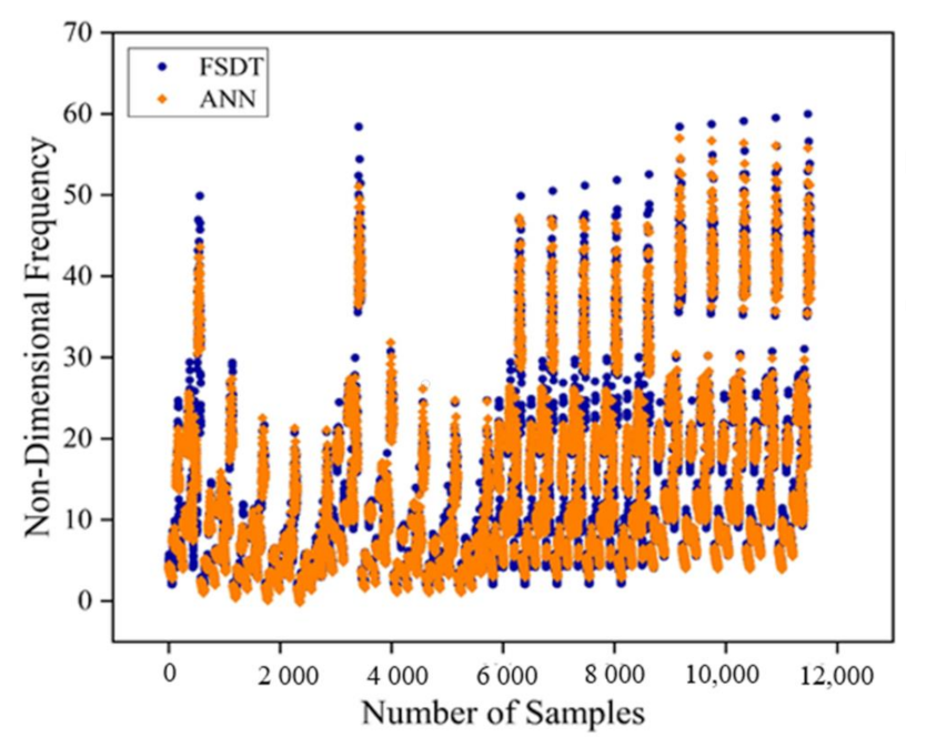
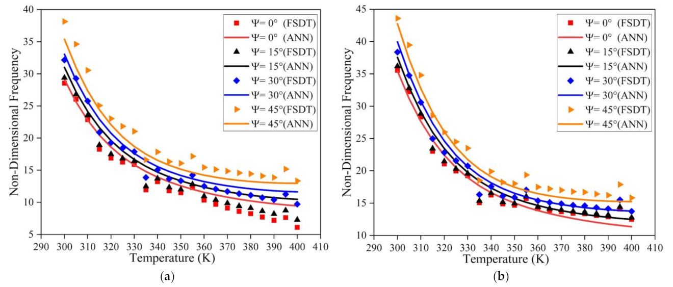
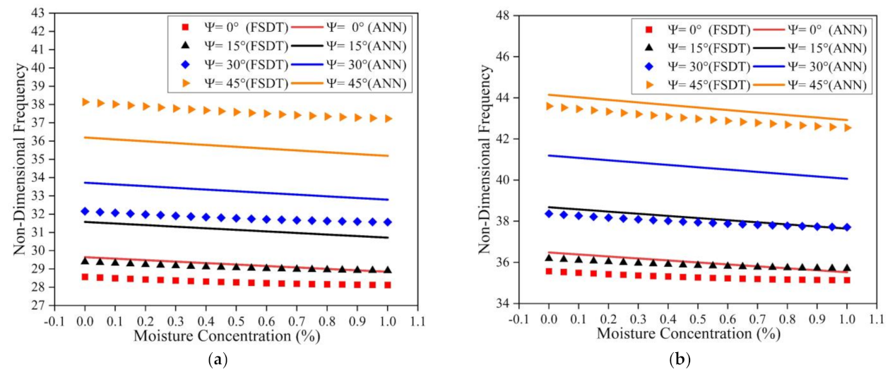
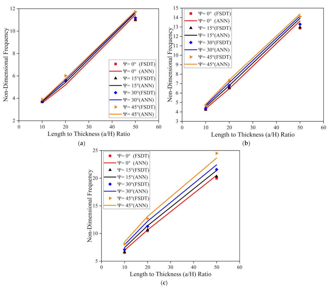
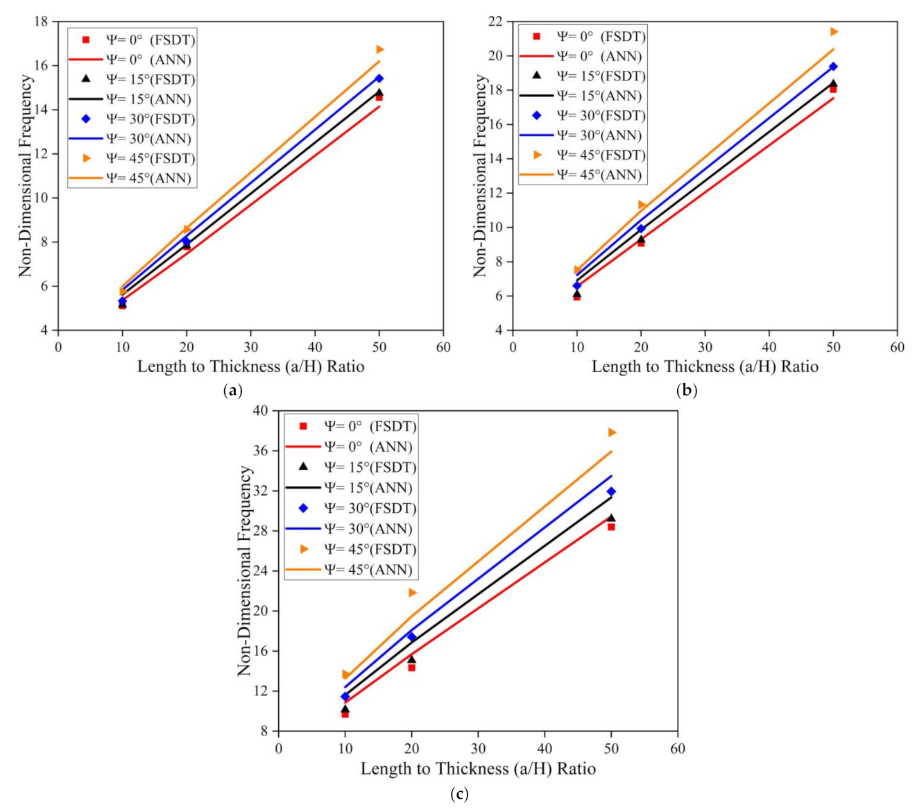
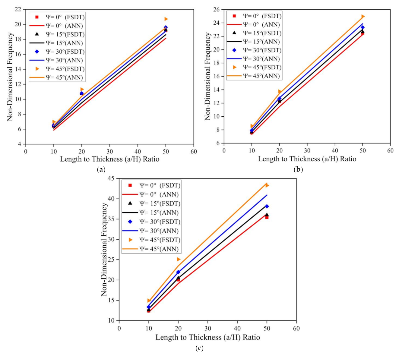
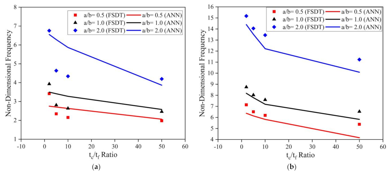
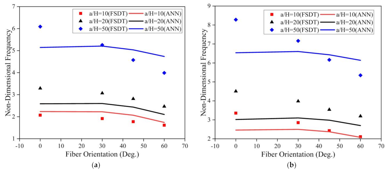
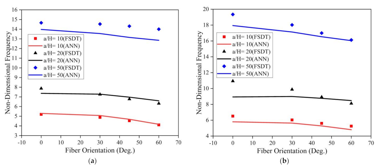
4.3. Model Simulation Results
5. Conclusions
Author Contributions
Funding
Institutional Review Board Statement
Informed Consent Statement
Data Availability Statement
Acknowledgments
Conflicts of Interest
Appendix A
Appendix B
Appendix C
Appendix D
- Nx, Ny, Nxy: In-plane initial internal force resultants per unit length
- Mx, My, Mxy: Initial internal moment resultants per unit length
- Qx, Qy: Initial transverse shear resultants.
Appendix E
- w1 and b1 are weight and bias of hidden layer
- w2 and b2 are weight and bias of hidden layer
References
- Suresh Kumar, R.; Ray, M.C. Active constrained layer damping of smart laminated composite sandwich plates using 1-3 piezoelectric composites. Int. J. Mech. Mater. Des. 2012, 8, 197–218. [Google Scholar] [CrossRef]
- Dat, N.D.; Quan, T.Q.; Mahesh, V.; Duc, N.D. Analytical solutions for nonlinear magneto-electro-elastic vibration of smart sandwich plate with carbon nanotube reinforced nanocomposite core in hygrothermal environment. Int. J. Mech. Sci. 2020, 186, 105906. [Google Scholar] [CrossRef]
- Ryu, J.; Lho, S.H.; Lee, C.H.; Ju, Y.K. Flexural behavior of prestressed sandwich plate system composite beams. Eng. Struct. 2020, 215, 110705. [Google Scholar] [CrossRef]
- Bouazza, M.; Zenkour, A.M. Hygro-thermo-mechanical buckling of laminated beam using hyperbolic refined shear deformation theory. Compos. Struct. 2020, 252, 112689. [Google Scholar] [CrossRef]
- Khare, R.K.; Garg, A.K.; Kant, T. Free vibration of sandwich laminates with two higher-order shear deformable facet shell element models. J. Sandw. Struct. Mater. 2005, 7, 221–244. [Google Scholar] [CrossRef]
- Biswal, M.; Sahu, S.K.; Asha, A.V. Experimental and numerical studies on free vibration of laminated composite shallow shells in hygrothermal environment. Compos. Struct. 2015, 127, 165–174. [Google Scholar] [CrossRef]
- Parhi, P.K.; Bhattacharyya, S.K.; Sinha, P.K. Hygrothermal effects on the dynamic behavior of multiple delaminated composite plates and shells. J. Sound Vib. 2001, 248, 195–214. [Google Scholar] [CrossRef]
- Zenkour, A.M.; Alghanmi, R.A. Hygro-thermo-electro-mechanical bending analysis of sandwich plates with FG core and piezoelectric faces. Mech. Adv. Mater. Struct. 2019, 28, 282–294. [Google Scholar] [CrossRef]
- Farrar, C.R.; Worden, K. An introduction to structural health monitoring. Philos. Trans. R. Soc. A Math. Phys. Eng. Sci. 2007, 365, 303–315. [Google Scholar] [CrossRef]
- Sharnappa Ganesan, N.; Sethuraman, R. Dynamic modeling of active constrained layer damping of composite beam under thermal environment. J. Sound Vib. 2007, 305, 728–749. [Google Scholar] [CrossRef]
- Nguyen, N.D.; Nguyen, T.K.; Nguyen, T.N.; Thai, H.T. New Ritz-solution shape functions for analysis of thermo-mechanical buckling and vibration of laminated composite beams. Compos. Struct. 2018, 184, 452–460. [Google Scholar] [CrossRef]
- Sobhy, M. An accurate shear deformation theory for vibration and buckling of FGM sandwich plates in hygrothermal environment. Int. J. Mech. Sci. 2016, 110, 62–77. [Google Scholar] [CrossRef]
- Mehar, K.; Panda, S.K.; Sharma, N. Numerical investigation and experimental verification of thermal frequency of carbon nanotube-reinforced sandwich structure. Eng. Struct. 2020, 211, 110444. [Google Scholar] [CrossRef]
- Dewangan, H.C.; Panda, S.K.; Sharma, N. Experimental Validation of Role of Cut-Out Parameters on Modal Responses of Laminated Composite—A Coupled FE Approach. Int. J. Appl. Mech. 2020, 12. [Google Scholar] [CrossRef]
- Katariya, P.V.; Panda, S.K.; Mehar, K. Theoretical modelling and experimental verification of modal responses of skewed laminated sandwich structure with epoxy-filled softcore. Eng. Struct. 2021, 228, 111509. [Google Scholar] [CrossRef]
- Biswal, M.; Sahu, S.K.; Asha, A.V. Dynamic Stability of Woven Fiber Laminated Composite Shallow Shells in Hygrothermal Environment. Int. J. Struct. Stab. Dyn. 2017, 17, 1–26. [Google Scholar] [CrossRef]
- Sayyad, A.S.; Ghumare, S.M. Thermomechanical Bending Analysis of FG Sandwich Plates Using a Quasi-Three-Dimensional Theory. J. Aerosp. Eng. 2021, 34, 04021007. [Google Scholar] [CrossRef]
- Zenkour, A.M.; El-Shahrany, H.D. Hygrothermal forced vibration of a viscoelastic laminated plate with magnetostrictive actuators resting on viscoelastic foundations. Int. J. Mech. Mater. Des. 2021, 17. [Google Scholar] [CrossRef]
- Garg, N.; Karkhanis, R.S.; Sahoo, R.; Maiti, P.R.; Singh, B.N. Trigonometric zigzag theory for static analysis of laminated composite and sandwich plates under hygro-thermo-mechanical loading. Compos. Struct. 2019, 209, 460–471. [Google Scholar] [CrossRef]
- Chandra, S.; Sepahvand, K.; Matsagar, V.A.; Marburg, S. Stochastic dynamic analysis of composite plate with random temperature increment. Compos. Struct. 2019, 226, 111159. [Google Scholar] [CrossRef]
- Rath, M.K.; Sahu, S.K. Vibration of woven fiber laminated composite plates in hygrothermal environment. JVC/J. Vib. Control 2012, 18, 1957–1970. [Google Scholar] [CrossRef]
- Sit, M.; Ray, C. Free vibration characteristics of glass and bamboo epoxy laminates under hygrothermal effect: A comparative approach. Compos. Part B Eng. 2019, 176, 107333. [Google Scholar] [CrossRef]
- Padhi, A.; Pandit, M.K. Bending and free vibration response of sandwich laminate under hygrothermal load using improved zigzag theory. J. Strain Anal. Eng. Des. 2017, 52, 288–297. [Google Scholar] [CrossRef]
- Daikh, A.A.; Bensaid, I.; Zenkour, A.M. Temperature dependent thermomechanical bending response of functionally graded sandwich plates. Eng. Res. Express 2020, 2. [Google Scholar] [CrossRef]
- Ding, A.; Wang, J.; Ni, A.; Li, S. Hygroscopic ageing of nonstandard size sandwich composites with vinylester-based composite faces and PVC foam core. Compos. Struct. 2018, 206, 194–201. [Google Scholar] [CrossRef]
- Ding, A.; Wang, J.; Ni, A.; Li, S. Assessment on the ageing of sandwich composites with vinylester-based composite faces and PVC foam core in various harsh environments. Compos. Struct. 2019, 213, 71–81. [Google Scholar] [CrossRef]
- Salehi, H.; Burgueño, R. Emerging artificial intelligence methods in structural engineering. Eng. Struct. 2018, 171, 170–189. [Google Scholar] [CrossRef]
- Atilla, D.; Sencan, C.; Goren Kiral, B.; Kiral, Z. Free vibration and buckling analyses of laminated composite plates with cutout. Arch. Appl. Mech. 2020, 90, 2433–2448. [Google Scholar] [CrossRef]
- Elshafey, A.A.; Dawood, N.; Marzouk, H.; Haddara, M. Crack width in concrete using artificial neural networks. Eng. Struct. 2013, 52, 676–686. [Google Scholar] [CrossRef]
- Sharma, N.; Swain, P.K.; Maiti, D.K.; Singh, B.N. Stochastic frequency analysis of laminated composite plate with curvilinear fiber. Mech. Adv. Mater. Struct. 2020, 1–16. [Google Scholar] [CrossRef]
- Mouloodi, S.; Rahmanpanah, H.; Burvill, C.; Gohari, S.; Davies, H.M.S. Experimental, regression learner, numerical, and artificial neural network analyses on a complex composite structure subjected to compression loading. Mech. Adv. Mater. Struct. 2020, 1–17. [Google Scholar] [CrossRef]
- Zenzen, R.; Khatir, S.; Belaidi, I.; Le Thanh, C.; Abdel Wahab, M. A modified transmissibility indicator and Artificial Neural Network for damage identification and quantification in laminated composite structures. Compos. Struct. 2020, 248. [Google Scholar] [CrossRef]
- Gomes, G.F.; de Almeida, F.A.; Junqueira, D.M.; da Cunha, S.S.; Ancelotti, A.C. Optimized damage identification in CFRP plates by reduced mode shapes and GA-ANN methods. Eng. Struct. 2019, 181, 111–123. [Google Scholar] [CrossRef]
- Al Rjoub, Y.S.; Alshatnawi, J.A. Free vibration of functionally-graded porous cracked plates. Structures 2020, 28, 2392–2403. [Google Scholar] [CrossRef]
- Oliver, G.A.; Ancelotti, A.C.; Gomes, G.F. Neural network-based damage identification in composite laminated plates using frequency shifts. Neural Comput. Appl. 2020, 3, 1–12. [Google Scholar] [CrossRef]
- Jalal, M.; Grasley, Z.; Gurganus, C.; Bullard, J.W. A new nonlinear formulation-based prediction approach using artificial neural network (ANN) model for rubberized cement composite. Eng. Comput. 2020. [Google Scholar] [CrossRef]
- Jodaei, A.; Jalal, M.; Yas, M.H. Free vibration analysis of functionally graded annular plates by state-space based differential quadrature method and comparative modeling by ANN. Compos. Part B Eng. 2012, 43, 340–353. [Google Scholar] [CrossRef]
- Ram, K.S.S.; Sinha, P.K. Hygrothermal effects on the free vibration of laminated composite plates. J. Sound Vib. 1992, 158, 133–148. [Google Scholar] [CrossRef]
- Kallannavar, V.; Kumaran, B.; Kattimani, S.C. Effect of temperature and moisture on free vibration characteristics of skew laminated hybrid composite and sandwich plates. Thin-Walled Struct. 2020, 157. [Google Scholar] [CrossRef]
- Yuan, W.X.; Dawe, D.J. Free vibration of sandwich plates with laminated faces. Int. J. Numer. Methods Eng. 2002, 54, 195–217. [Google Scholar] [CrossRef]
- Garg, A.K.; Khare, R.K.; Kant, T. Free vibration of skew fiber-reinforced composite and sandwich laminates using a shear deformable finite element model. J. Sandw. Struct. Mater. 2006, 8, 33–53. [Google Scholar] [CrossRef]
- Behera, R.R.; Ghadai, R.K.; Kalita, K.; Banerjee, S. Simultaneous prediction of delamination and surface roughness in drilling GFRP composite using ANN. Int. J. Plast. Technol. 2016, 20, 424–450. [Google Scholar] [CrossRef]
- Cascardi, A.; Micelli, F.; Aiello, M.A. An Artificial Neural Networks model for the prediction of the compressive strength of FRP-confined concrete circular columns. Eng. Struct. 2017, 140, 199–208. [Google Scholar] [CrossRef]


| Properties | Units | Graphite-Epoxy [38] | Viscoelastic Core [10] |
|---|---|---|---|
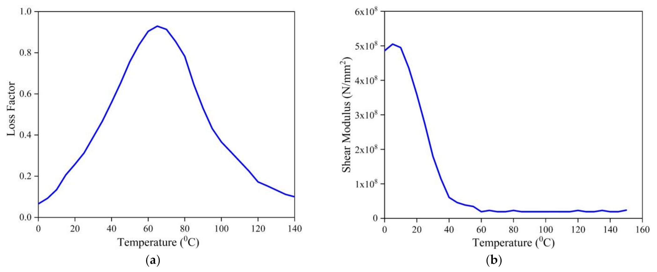
| Elastic Moduli | GPa | Table 2a,b | Figure 2 |
| Density | kg/m3 | 1600 | 1200 |
| Poisson’s Ratio | m/m | υ12 = 0.3 | υ12 = 0.49 |
| Coefficient of moisture expansion | - | β1 = 0 β2 = 0.44 | - |
| Coefficient of thermal expansion | /K | α1 = −0.3 × 10⁻⁶ α2 = 28.1 × 10⁻⁶ | - |
| (a) | |||||
| Elastic Moduli (GPa) | 0.00 | 0.25 | 0.50 | 0.75 | 1.00 |
| E1 | 130 | 130 | 130 | 130 | 130 |
| E2 | 9.50 | 9.25 | 9.00 | 8.75 | 8.50 |
| G12 = G13 | 6.0 | 6.0 | 6.0 | 6.0 | 6.0 |
| (b) | |||||
| Elastic Moduli (GPa) | 300 | 325 | 350 | 375 | 400 |
| E1 | 130 | 130 | 130 | 130 | 130 |
| E2 | 9.50 | 8.50 | 8.00 | 7.50 | 7.00 |
| G12 = G13 | 6.0 | 6.0 | 5.5 | 5.0 | 4.75 |
| Skew Angle | Mesh Size | Temperature (K) | Moisture Concentration (%) | ||||||
|---|---|---|---|---|---|---|---|---|---|
| 300 | 325 | 350 | 375 | 0.00 | 0.25 | 0.50 | 0.75 | ||
| 0° | 4 × 4 | 34.2394 | 34.2046 | 34.1697 | 34.1350 | 34.2394 | 34.1720 | 34.1048 | 34.0377 |
| 8 × 8 | 35.6470 | 35.6113 | 35.5756 | 35.5399 | 35.6470 | 35.5775 | 35.5080 | 35.4386 | |
| 12 × 12 | 35.8753 | 35.8404 | 35.8054 | 35.7705 | 35.8753 | 35.8066 | 35.7381 | 35.6696 | |
| Ref. [39] | 35.8753 | 35.8404 | 35.8054 | 35.7705 | 35.8753 | 35.8066 | 35.7381 | 35.6696 | |
| 15° | 4 × 4 | 34.6184 | 34.5807 | 34.5431 | 34.5055 | 34.6184 | 34.5470 | 34.4758 | 34.4047 |
| 8 × 8 | 36.0444 | 36.0060 | 35.9675 | 35.9292 | 36.0444 | 35.9710 | 35.8977 | 35.8246 | |
| 12 × 12 | 36.2630 | 36.2253 | 36.1875 | 36.1498 | 36.2630 | 36.1904 | 36.1179 | 36.0455 | |
| Ref. [39] | 36.2630 | 36.2253 | 36.1875 | 36.1498 | 36.2630 | 36.1904 | 36.1179 | 36.0455 | |
| 30° | 4 × 4 | 35.9073 | 35.8608 | 35.8143 | 35.7679 | 35.9073 | 35.8232 | 35.7392 | 35.6555 |
| 8 × 8 | 37.3947 | 37.3477 | 37.3008 | 37.2540 | 37.3947 | 37.3092 | 37.2240 | 37.1390 | |
| 12 × 12 | 37.5810 | 37.5345 | 37.4880 | 37.4415 | 37.5810 | 37.4960 | 37.4111 | 37.3265 | |
| Ref. [39] | 37.5810 | 37.5345 | 37.4880 | 37.4415 | 37.5810 | 37.4960 | 37.4111 | 37.3265 | |
| 45° | 4 × 4 | 38.7608 | 38.6980 | 38.6352 | 38.5725 | 38.7608 | 38.6532 | 38.5459 | 38.4389 |
| 8 × 8 | 40.3527 | 40.2904 | 40.2282 | 40.1661 | 40.3527 | 40.2455 | 40.1385 | 40.0319 | |
| 12 × 12 | 40.4746 | 40.4122 | 40.3498 | 40.2875 | 40.4746 | 40.3669 | 40.2594 | 40.1523 | |
| Ref. [39] | 40.4746 | 40.4122 | 40.3498 | 40.2875 | 40.4746 | 40.3669 | 40.2594 | 40.1523 | |
| 60° | 4 × 4 | 45.2802 | 45.1912 | 45.1024 | 45.0137 | 45.2802 | 45.1346 | 44.9893 | 44.8446 |
| 8 × 8 | 46.9400 | 46.8524 | 46.7650 | 46.6778 | 46.9400 | 46.7961 | 46.6526 | 46.5097 | |
| 12 × 12 | 46.9691 | 46.8804 | 46.7920 | 46.7037 | 46.9691 | 46.8233 | 46.6781 | 46.5335 | |
| Ref. [39] | 46.9691 | 46.8804 | 46.7920 | 46.7037 | 46.9691 | 46.8233 | 46.6781 | 46.5335 | |
| Lamination Scheme | Source | Skew Angles | ||
|---|---|---|---|---|
| 0° | 15° | 30° | ||
| 90°/0°/C/0°/90° | FSDT [41] | 172.7237 | 184.5342 | 225.9660 |
| HSDT [41] | 158.0954 | 167.8775 | 201.7029 | |
| Spline finite strip method [40] | 159.30 | - | - | |
| Present | 157.20 | 165.10 | 190.85 | |
| 0°/90°/C/0°/90° | FSDT [41] | 166.3086 | 177.6942 | 217.7630 |
| HSDT [41] | 152.2992 | 161.7182 | 194.3770 | |
| Spline finite strip method [40] | 152.58 | - | - | |
| Present | 150.78 | 158.48 | 183.61 | |
| 0°/90°/C/90°/0° | FSDT [41] | 159.8275 | 170.7568 | 209.3430 |
| HSDT [41] | 146.5089 | 155.5495 | 186.9801 | |
| Spline finite strip method [40] | 145.99 | - | - | |
| Present | 144.40 | 151.88 | 176.31 | |
| Parameters | Range |
|---|---|
| Temperature (K) | 300, 325, 350, 375, 400 |
| Moisture (%) | 0, 0.25, 0.5, 0.75, 1 |
| Boundary conditions | SSSS, CCCC |
| Length to breadth (a/b) ratio | 0.5, 1, 2 |
| Length to thickness (a/H) ratio | 10, 20, 50 |
| Core thickness to thickness of face sheet (tc/tf) ratio | 2, 5, 10, 50 |
| Fiber orientation of composite face sheets | 0°, 30°, 45°, 60° |
| Skew angle | 0°, 15°, 30°, 45° |
Publisher’s Note: MDPI stays neutral with regard to jurisdictional claims in published maps and institutional affiliations. |
© 2021 by the authors. Licensee MDPI, Basel, Switzerland. This article is an open access article distributed under the terms and conditions of the Creative Commons Attribution (CC BY) license (https://creativecommons.org/licenses/by/4.0/).
Share and Cite
Kallannavar, V.; Kattimani, S.; Soudagar, M.E.M.; Mujtaba, M.A.; Alshahrani, S.; Imran, M. Neural Network-Based Prediction Model to Investigate the Influence of Temperature and Moisture on Vibration Characteristics of Skew Laminated Composite Sandwich Plates. Materials 2021, 14, 3170. https://doi.org/10.3390/ma14123170
Kallannavar V, Kattimani S, Soudagar MEM, Mujtaba MA, Alshahrani S, Imran M. Neural Network-Based Prediction Model to Investigate the Influence of Temperature and Moisture on Vibration Characteristics of Skew Laminated Composite Sandwich Plates. Materials. 2021; 14(12):3170. https://doi.org/10.3390/ma14123170
Chicago/Turabian StyleKallannavar, Vinayak, Subhaschandra Kattimani, Manzoore Elahi M. Soudagar, M. A. Mujtaba, Saad Alshahrani, and Muhammad Imran. 2021. "Neural Network-Based Prediction Model to Investigate the Influence of Temperature and Moisture on Vibration Characteristics of Skew Laminated Composite Sandwich Plates" Materials 14, no. 12: 3170. https://doi.org/10.3390/ma14123170