
Chloride Diffusion Property of Hybrid Basalt–Polypropylene Fibre-Reinforced Concrete in a Chloride–Sulphate Composite Environment under Drying–Wetting Cycles


Abstract
:1. Introduction
2. Materials and Methods
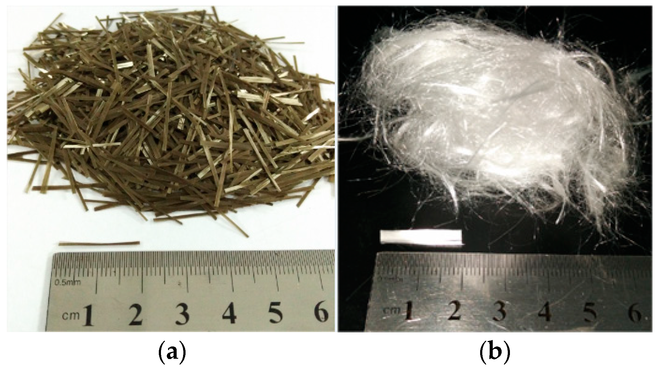
2.1. Materials and Mix Proportions
2.2. Experimental Program
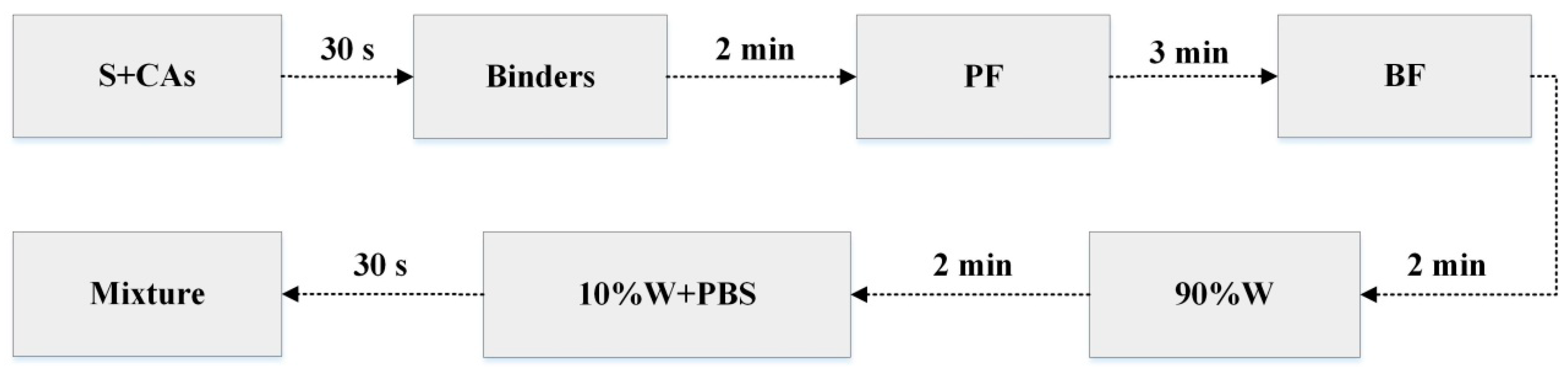
2.2.1. Experimental Procedure
2.2.2. Free Chloride Content Test
2.2.3. Pore Solution pH Test
2.2.4. Microscopic Testing
2.2.5. Theoretical Porosity
3. Results and Discussion
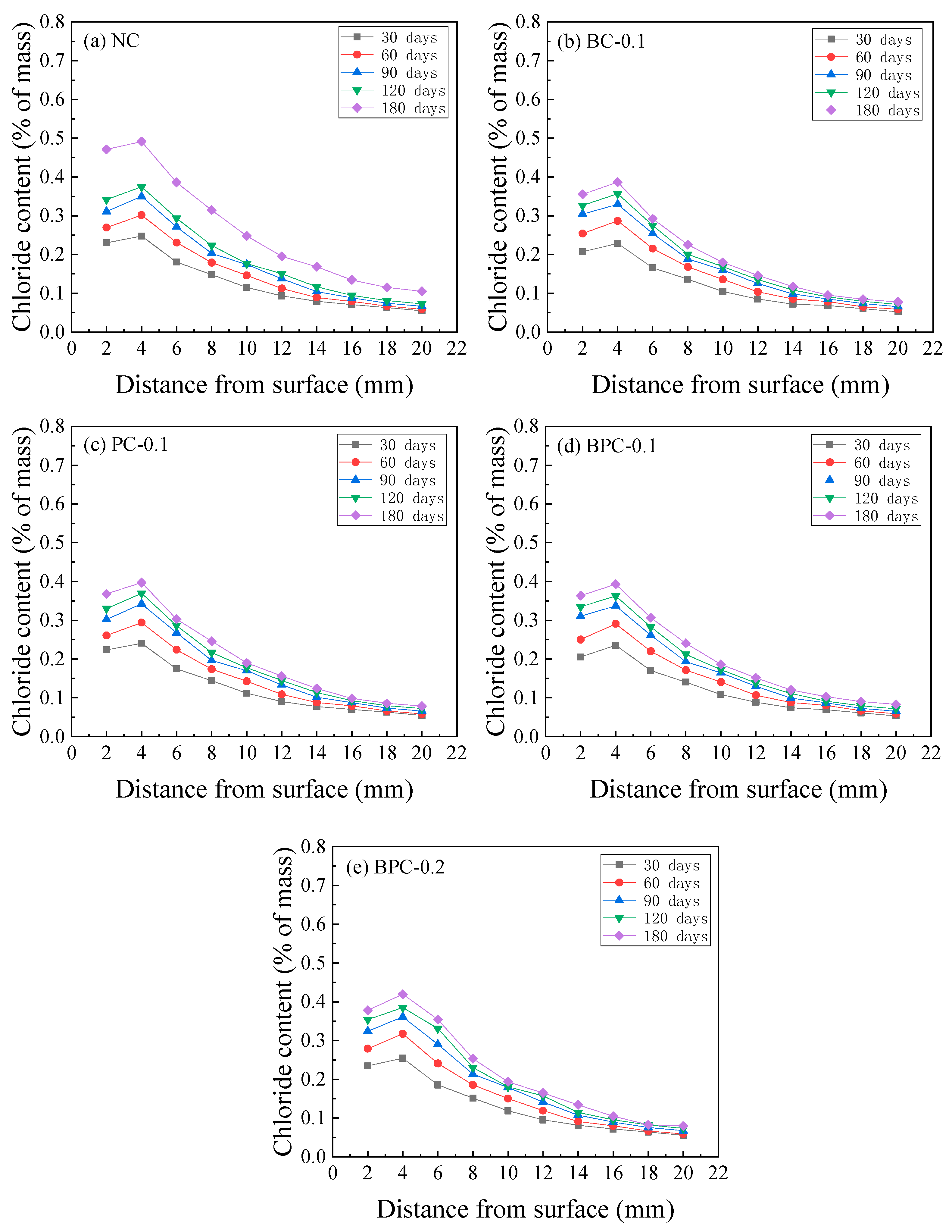
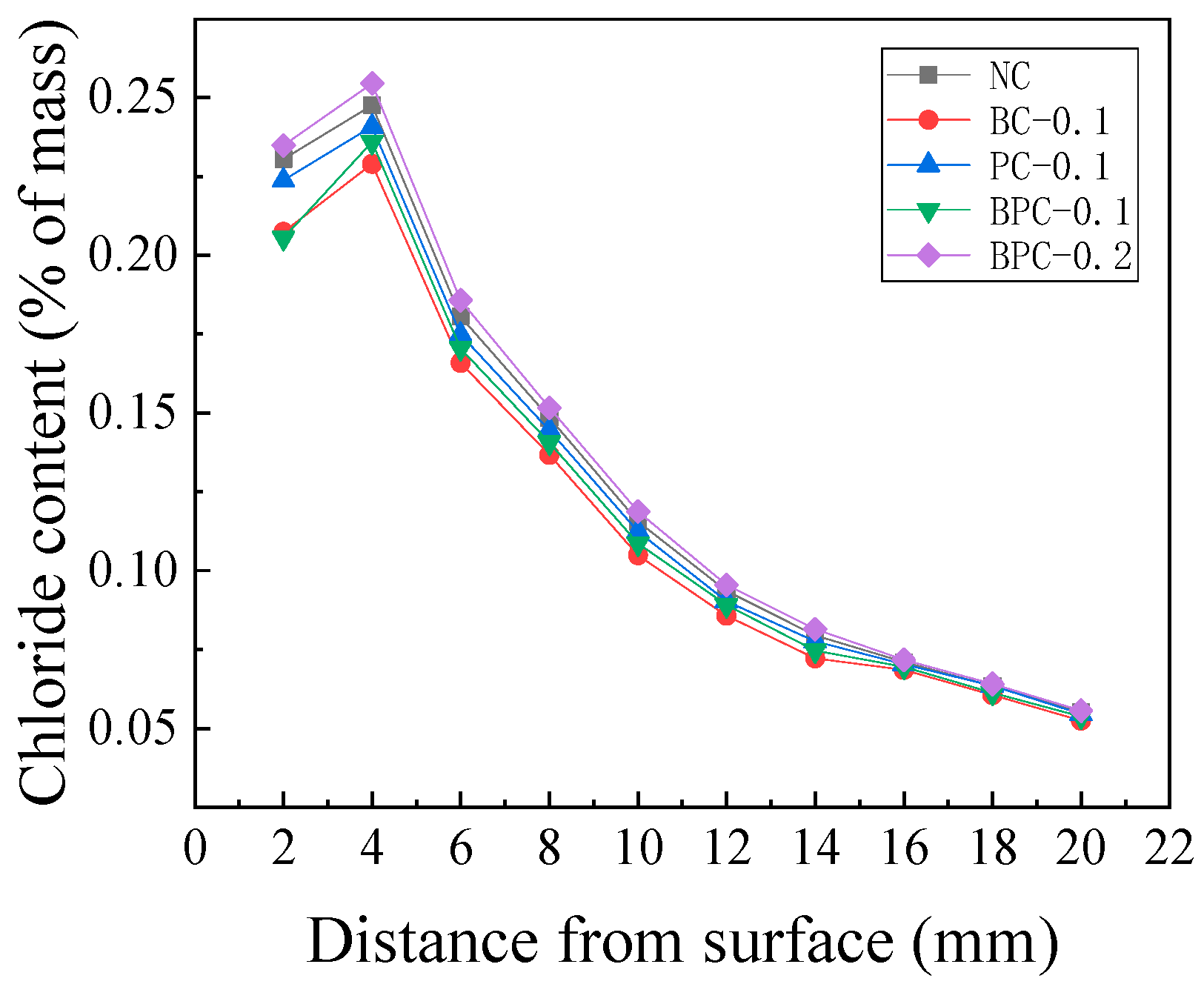
3.1. Chloride Content
3.2. Effect of Fibre on the Chloride Diffusion Property of Concrete
3.2.1. Early Stage of Erosion
3.2.2. Late Stage of Erosion
3.3. Pore Solution pH Distribution
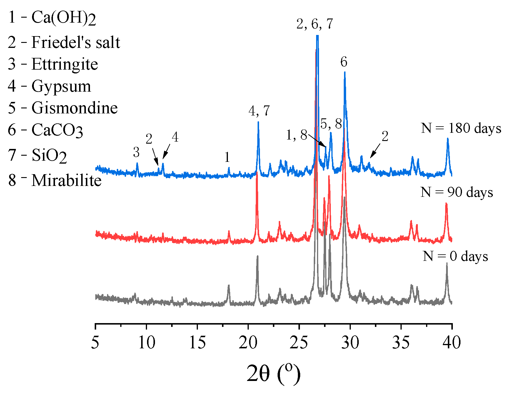
3.4. XRD Analysis
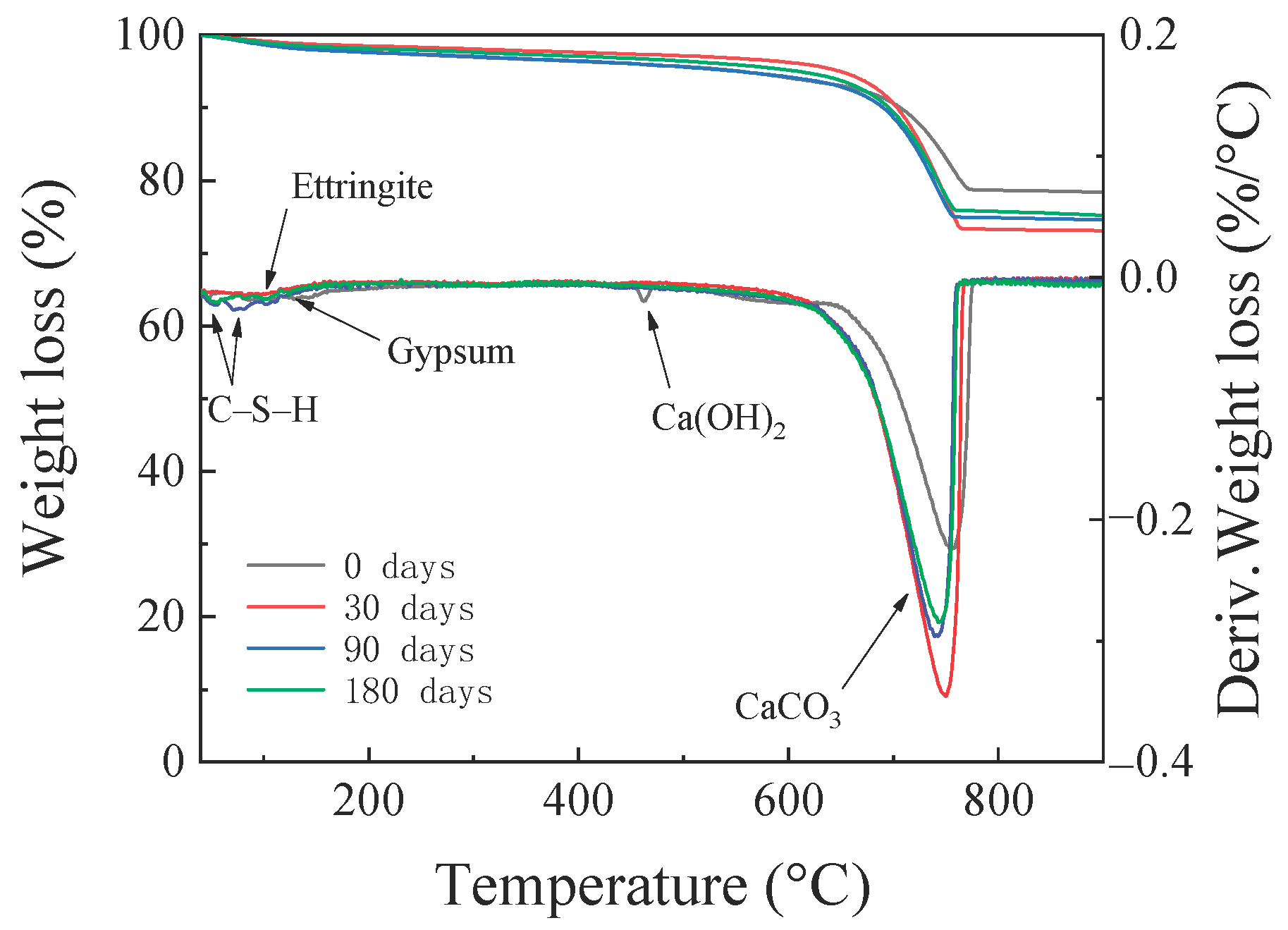
3.5. TG Analysis
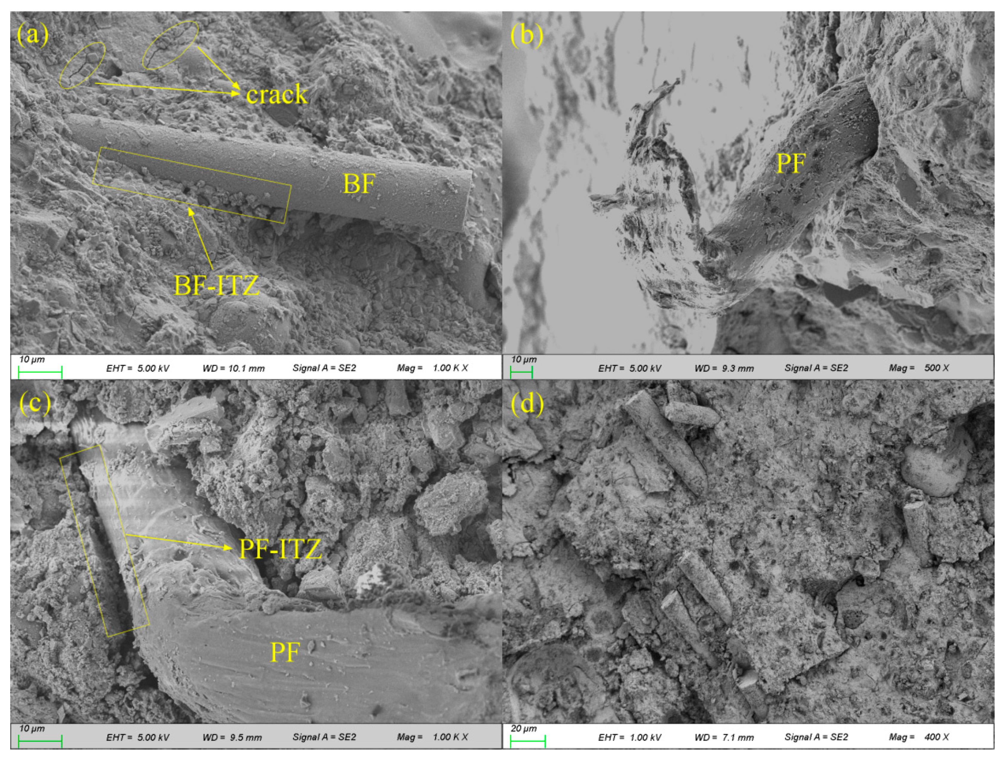
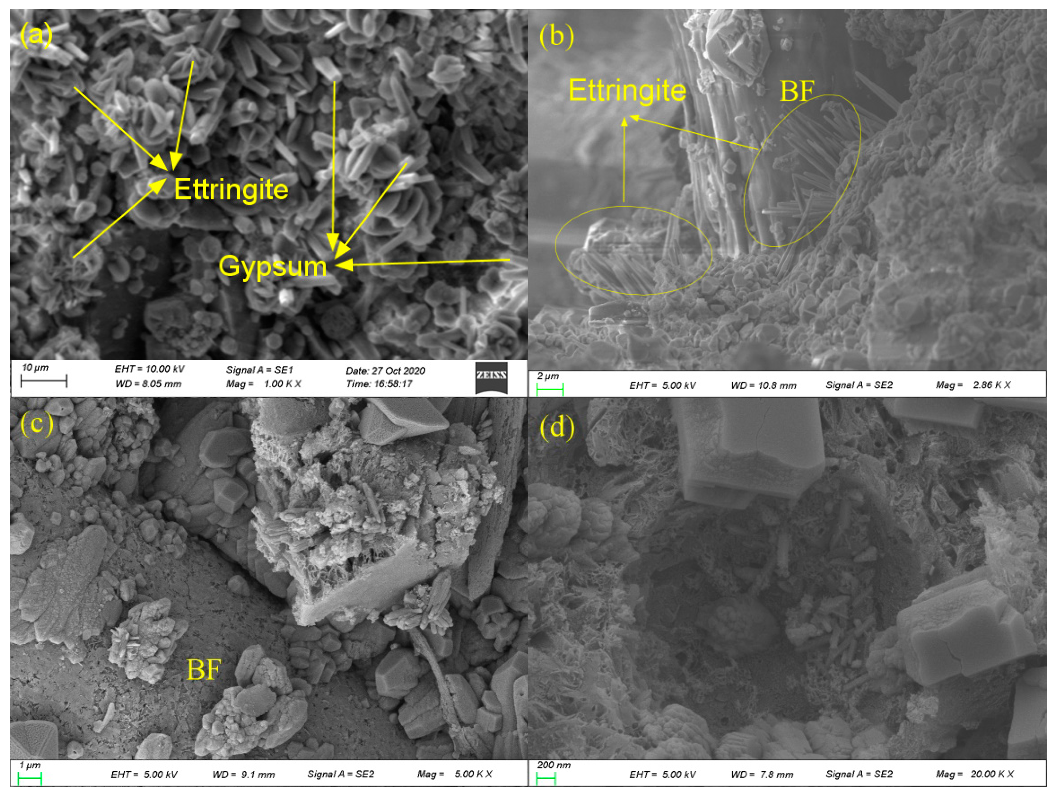
3.6. SEM Analysis
4. Conclusions
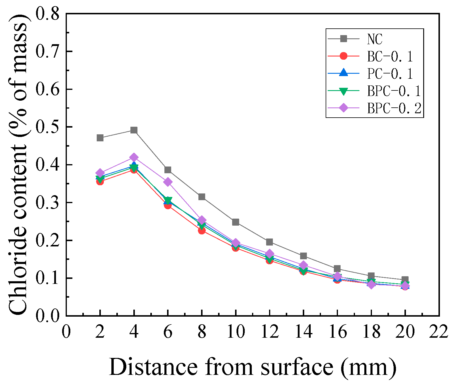
- There is a peak at a certain depth from the specimen surface in the chloride content distribution curve due to drying–wetting cycles and the “ink bottle–bundle tube” like microstructure of concrete pores; however, the fibre and erosion time have little effect on the depth of the peak point. The peak depth was approximately 4 mm in each group of specimens after each erosion period.
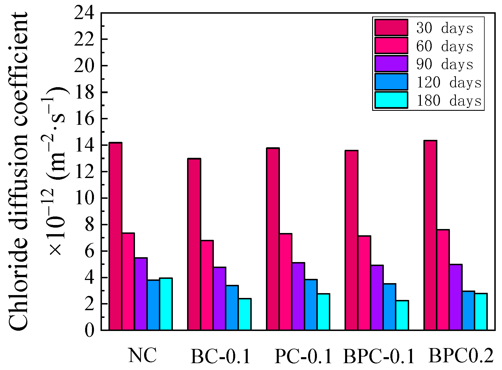
- When the fibre content was 0.1%, the addition of BF, PF, and hybrid BF–PF improved the chloride attack resistance of concrete at the early stage of erosion. Adding 0.1% BF had the best effect, which reduced the apparent chloride diffusion coefficient by 8.5% after 30 days of erosion. Moreover, the chloride attack resistance of concrete at the early stage of erosion was reduced when 0.2% hybrid BF–PF was blended.
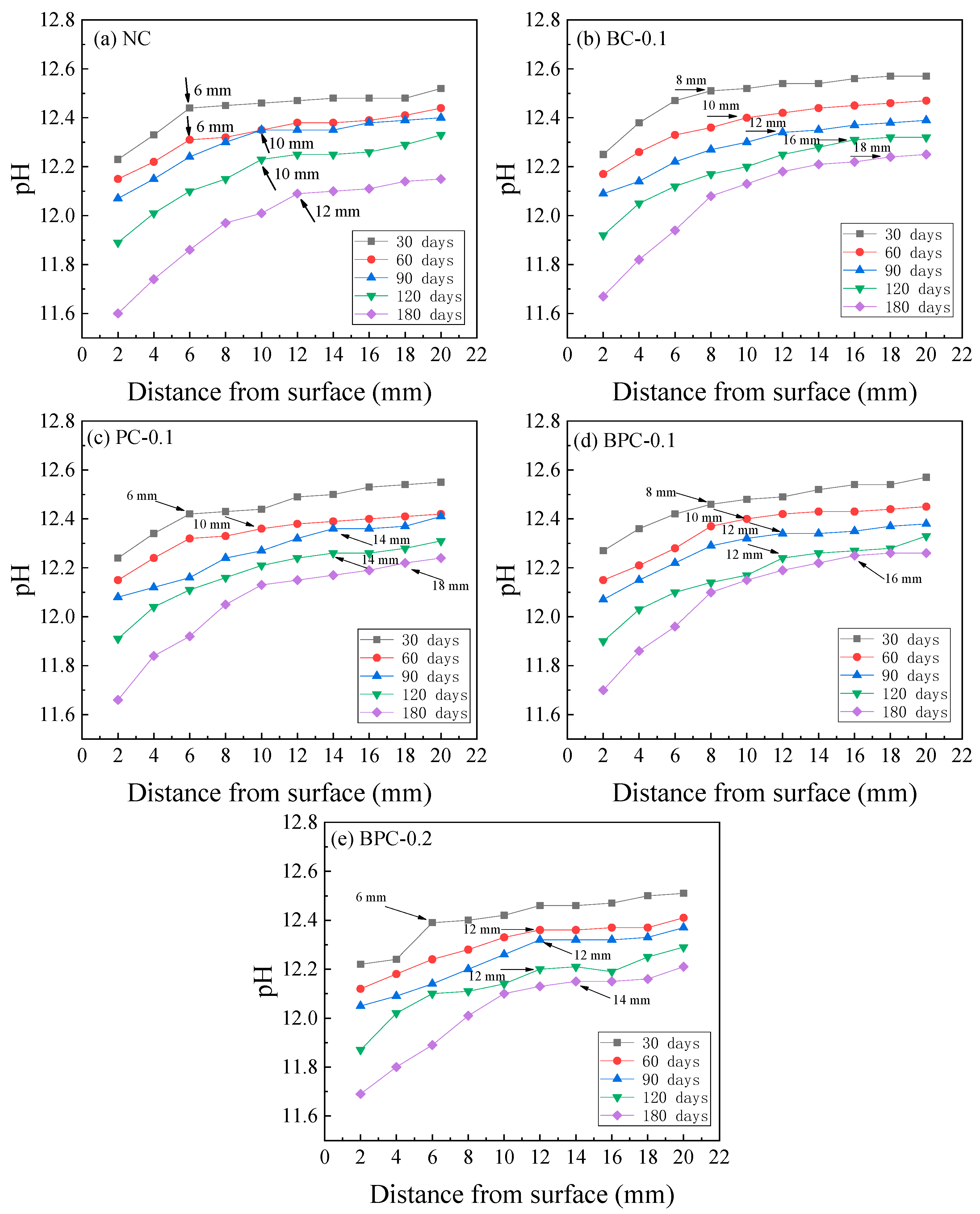
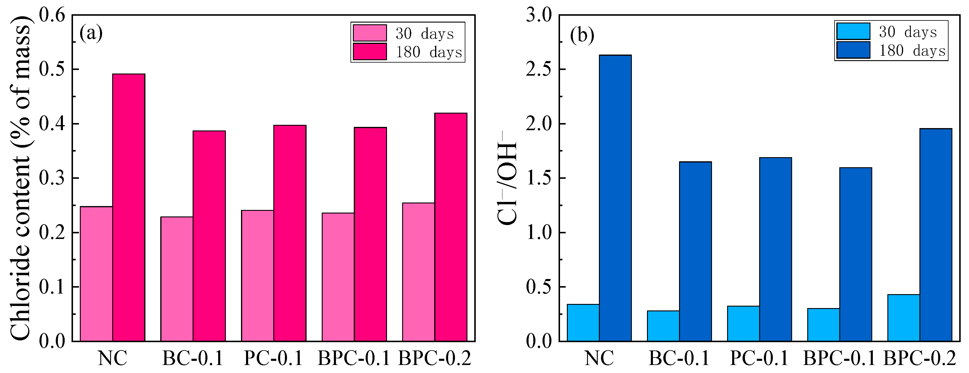
- The sulphate in the composite solution decreased and increased the chloride penetration rate in the concrete at the early and late stages of erosion, respectively. In addition, sulphate erosion also led to a decrease in the alkalinity of the pore liquid phase of concrete, in which the growth rate of the Cl−/OH− ratio was 2.8 to 3.9 times the growth rate of the chloride content.
- The positive effect of the fibre gradually appeared as the erosion time was extended. After 180 days of erosion, the apparent chloride diffusion coefficients of the specimens with fibre were reduced by 29.4–43.1% compared with that of the control specimen NC, while the Cl−/OH− ratios were reduced by 25.7–39.3%. The specimen blended with 0.1% hybrid BF–PF demonstrated the smallest apparent chloride diffusion coefficient and Cl−/OH− ratio at the late stage of erosion.
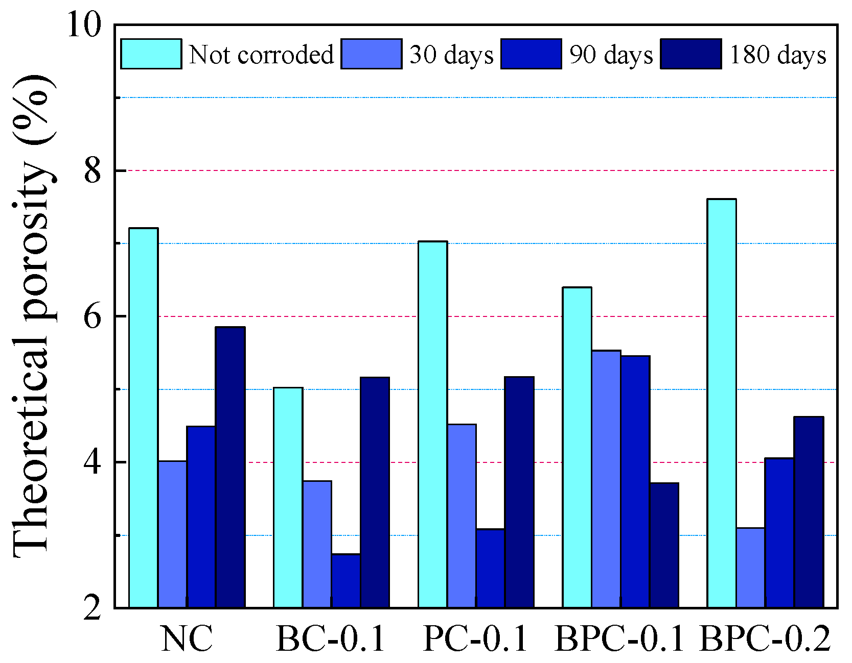
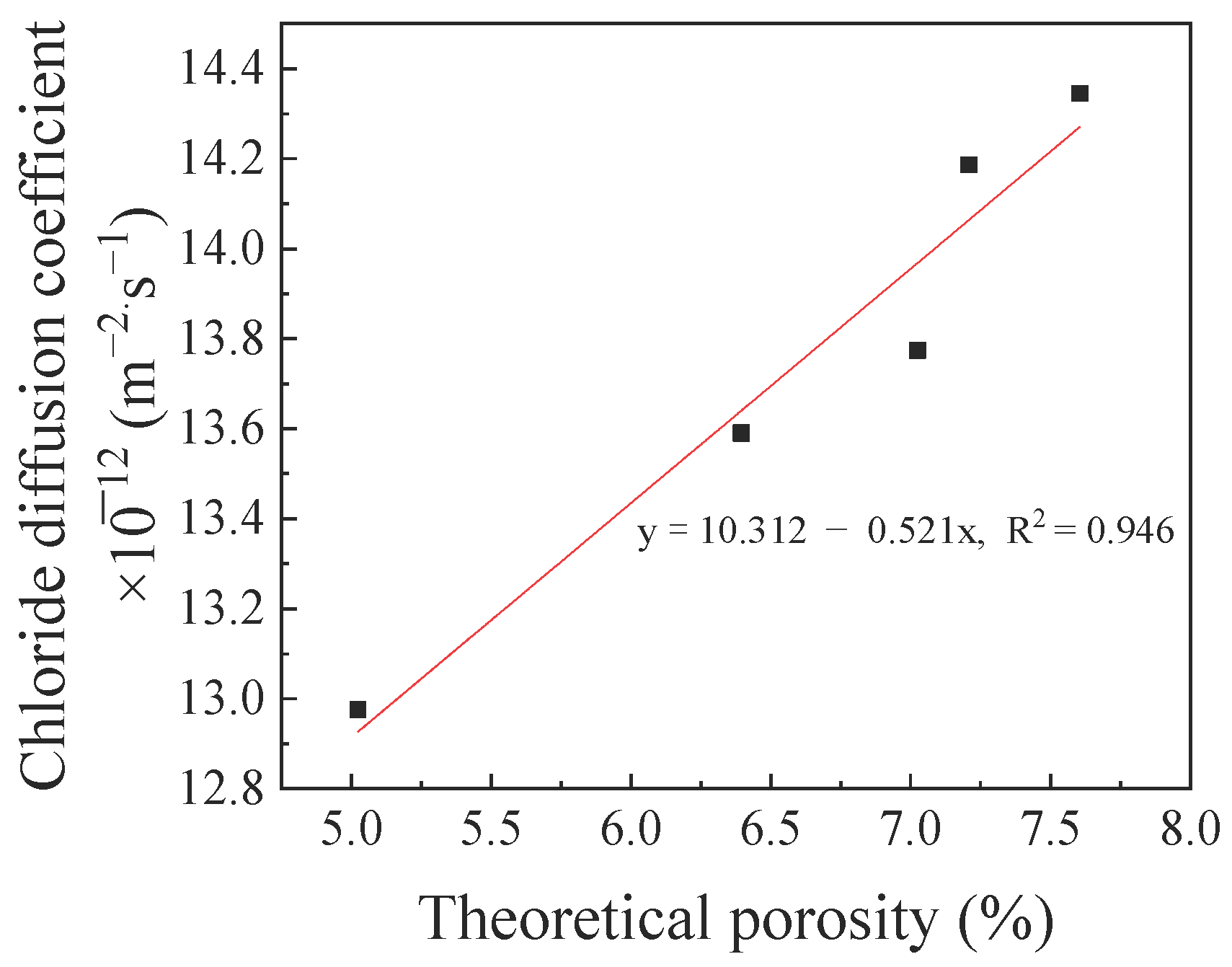
- The theoretical porosity of concrete decreases with the addition of fibre; however, an excessive amount of fibre increases the porosity. The SEM results show that BF has a better bonding performance with the concrete matrix and a thinner fibre-matrix ITZ with lower porosity compared with PF. The corrosion products filled the pores inside the concrete as well as the fibre-matrix ITZ during the erosion process, thus reducing the porosity of the concrete.
Author Contributions
Funding
Institutional Review Board Statement
Informed Consent Statement
Data Availability Statement
Conflicts of Interest
References
- Niu, D.T. Durability and Life Prediction of Concrete Structures; Science Press: Beijing, China, 2003. [Google Scholar]
- Zollo, R.F. Fiber-reinforced concrete: An overview after 30 years of development. Cem. Concr. Compos. 1997, 19, 107–122. [Google Scholar] [CrossRef]
- Yao, W.; Li, J.; Wu, K. Mechanical properties of hybrid fiber-reinforced concrete at low fiber volume fraction. Cem. Concr. Res. 2003, 33, 27–30. [Google Scholar] [CrossRef]
- Brandt, A.M. Fibre reinforced cement-based (FRC) composites after over 40 years of development in building and civil engineering. Compos. Struct. 2008, 86, 3–9. [Google Scholar] [CrossRef]
- Marcalikova, Z.; Cajka, R.; Bilek, V.; Bujdos, D.; Sucharda, O. Determination of mechanical characteristics for fiber-reinforced concrete with straight and hooked fibers. Crystals 2020, 10, 545. [Google Scholar] [CrossRef]
- Li, X.K.; Sun, L.; Zhou, Y.Y.; Zhao, S.B. A review of stee-polypropylene hybrid fiber reinforced concrete. Appl. Mech. Mater. 2012, 238, 26–32. [Google Scholar] [CrossRef]
- El-Hamrawy, M.I.; Saba, A.M. Fracture energy of hybrid fiber reinforced concrete. Reg. Conf. Civ. Eng. Technol. 2007, 3, 232–234. [Google Scholar]
- Blunt, J.; Jen, G.; Ostertag, C.P. Enhancing corrosion resistance of reinforced concrete structures with hybrid fiber reinforced concrete. Corros. Sci. 2015, 92, 182–191. [Google Scholar] [CrossRef]
- Fu, Q.; Bu, M.; Xu, W.; Chen, L.; Li, D.; He, J.; Kou, H.; Li, H. Comparative analysis of dynamic constitutive response of hybrid fibre-reinforced concrete with different matrix strengths. Int. J. Impact Eng. 2021, 148, 103763. [Google Scholar] [CrossRef]
- Fu, Q.; Xu, W.; Li, D.; Li, N.; Niu, D.; Zhang, L.; Guo, B.; Zhang, Y. Dynamic compressive behaviour of hybrid basalt-polypropylene fibre-reinforced concrete under confining pressure: Experimental characterisation and strength criterion. Cem. Concr. Compos. 2021, 118, 103954. [Google Scholar] [CrossRef]
- Bankir, M.B.; Sevim, U.K. Performance optimization of hybrid fiber concretes against acid and sulfate attack. J. Build. Eng. 2020, 32, 101443. [Google Scholar] [CrossRef]
- Afroughsabet, V.; Biolzi, L.; Monteiro, P.J.M. The effect of steel and polypropylene fibers on the chloride diffusivity and drying shrinkage of high-strength concrete. Compos. Part B Eng. 2018, 139, 84–96. [Google Scholar] [CrossRef]
- Frazão, C.; Camões, A.; Barros, J.; Gonçalves, D. Durability of steel fiber reinforced self-compacting concrete. Constr. Build. Mater. 2015, 80, 155–166. [Google Scholar] [CrossRef] [Green Version]
- Niu, D.; Su, L.; Luo, Y.; Huang, D.; Luo, D. Experimental study on mechanical properties and durability of basalt fiber reinforced coral aggregate concrete. Constr. Build. Mater. 2020, 237, 117628. [Google Scholar] [CrossRef]
- Smarzewski, P. Flexural toughness of high-performance concrete with basalt and polypropylene short fibres. Adv. Civ. Eng. 2018, 2018, 5024353. [Google Scholar] [CrossRef] [Green Version]
- Smarzewski, P. Influence of basalt-polypropylene fibres on fracture properties of high performance concrete. Compos. Struct. 2019, 209, 23–33. [Google Scholar] [CrossRef]
- Shi, F.; Pham, T.M.; Hao, H.; Hao, Y. Post-cracking behaviour of basalt and macro polypropylene hybrid fibre reinforced concrete with different compressive strengths. Constr. Build. Mater. 2020, 262, 120108. [Google Scholar] [CrossRef]
- Cao, L. Experimental Study on Freeze-Thaw Cycle of Basalt-Polypropylene Hybrid Fiber Reinforced Concrete. Master’s Thesis, Harbin Engineering University, Harbin, China, 2017. [Google Scholar]
- Wang, C.F. Study on Durability of Polypropylene Fiber Concrete in Chloride Environment. Ph.D. Thesis, Xi’an University of Architecture and Technology, Xi’an, China, 2012. [Google Scholar]
- Lin, G.; Liu, Y.; Xiang, Z. Numerical modeling for predicting service life of reinforced concrete structures exposed to chloride environments. Cem. Concr. Compos. 2010, 32, 571–579. [Google Scholar] [CrossRef]
- Nagesh, M.; Bishwajit, B. Modeling of chloride diffusion in concrete and determination of diffusion coefficients. ACI Mater. J. 1998, 95, 113–120. [Google Scholar]
- Aköz, F.; Türker, F.; Koral, S.; Yüzer, N. Effects of sodium sulfate concentration on the sulfate resistance of mortars with and without silica fume. Cem. Concr. Res. 1995, 25, 1360–1368. [Google Scholar] [CrossRef]
- Kumar, S.; Rao, C.V.S.K. Strength loss in concrete due to varying sulfate exposures. Cem. Concr. Res. 1995, 25, 57–62. [Google Scholar] [CrossRef]
- Xu, J.; Zhang, C.; Jiang, L.; Tang, L.; Gao, G.; Xu, Y. Releases of bound chlorides from chloride-admixed plain and blended cement pastes subjected to sulfate attacks. Constr. Build. Mater. 2013, 45, 53–59. [Google Scholar] [CrossRef]
- Chen, Y.; Gao, J.; Tang, L.; Li, X. Resistance of concrete against combined attack of chloride and sulfate under drying–wetting cycles. Constr. Build. Mater. 2016, 106, 650–658. [Google Scholar] [CrossRef]
- Maes, M.; De Belie, N. Resistance of concrete and mortar against combined attack of chloride and sodium sulphate. Cem. Concr. Compos. 2014, 53, 59–72. [Google Scholar] [CrossRef]
- Mavropoulou, N.; Katsiotis, N.; Giannakopoulos, J.; Koutsodontis, K.; Papageorgiou, D.; Chaniotakis, E.; Katsioti, M.; Tsakiridis, P.E. Durability evaluation of cement exposed to combined action of chloride and sulphate ions at elevated temperature: The role of limestone filler. Constr. Build. Mater. 2016, 124, 558–565. [Google Scholar] [CrossRef]
- Stroh, J.; Meng, B.; Emmerling, F. Deterioration of hardened cement paste under combined sulphate-chloride attack investigated by synchrotron XRD. Solid State Sci. 2016, 56, 29–44. [Google Scholar] [CrossRef]
- Li, D.; Niu, D.T.; Fu, Q.; Luo, D. Fractal characteristics of pore structure of hybrid Basalt–Polypropylene fibre-reinforced concrete. Cem. Concr. Compos. 2020, 109, 103555. [Google Scholar] [CrossRef]
- GB/T 50344-2004. Technical Standard of Inspection of Building Structure; China Building Industry Press: Beijing, China, 2004. [Google Scholar]
- Zajac, M.; Hoock, S.; Stabler, C.; Ben Haha, M. Effect of hydration kinetics on properties of compositionally similar binders. Cem. Concr. Res. 2017, 101, 13–24. [Google Scholar] [CrossRef]
- Hong, K.; Hooton, R.D. Effects of fresh water exposure on chloride contaminated concrete. Cem. Concr. Res. 2000, 30, 1199–1207. [Google Scholar] [CrossRef]
- Ye, H.; Jin, N.; Jin, X.; Fu, C. Model of chloride penetration into cracked concrete subject to drying–wetting cycles. Constr. Build. Mater. 2012, 36, 259–269. [Google Scholar] [CrossRef]
- Yu, Z.; Chen, Y.; Liu, P.; Wang, W. Accelerated simulation of chloride ingress into concrete under drying–wetting alternation condition chloride environment. Constr. Build. Mater. 2015, 93, 205–213. [Google Scholar] [CrossRef]
- Papakonstantinou, K.G.; Shinozuka, M. Probabilistic model for steel corrosion in reinforced concrete structures of large dimensions considering crack effects. Eng. Struct. 2013, 57, 306–326. [Google Scholar] [CrossRef]
- Gao, Y.; De Schutter, G.; Ye, G.; Huang, H.; Tan, Z.; Wu, K. Porosity characterization of ITZ in cementitious composites: Concentric expansion and overflow criterion. Constr. Build. Mater. 2013, 38, 1051–1057. [Google Scholar] [CrossRef]
- Ikumi, T.; Cavalaro, S.H.P.; Segura, I. The role of porosity in external sulphate attack. Cem. Concr. Compos. 2019, 97, 1–12. [Google Scholar] [CrossRef] [Green Version]
- Ranjbar, N.; Talebian, S.; Mehrali, M.; Kuenzel, C.; Cornelis Metselaar, H.S.; Jumaat, M.Z. Mechanisms of interfacial bond in steel and polypropylene fiber reinforced geopolymer composites. Compos. Sci. Technol. 2016, 122, 73–81. [Google Scholar] [CrossRef]
- Boulfiza, M.; Sakai, K.; Banthia, N.; Yoshida, H. Prediction of chloride ions ingress in uncracked and cracked concrete. Aci Mater. J. 2003, 100, 38–48. [Google Scholar]
- Li, J.J.; Niu, J.G.; Wan, C.J.; Jin, B.; Yin, Y.L. Investigation on mechanical properties and microstructure of high performance polypropylene fiber reinforced lightweight aggregate concrete. Constr. Build. Mater. 2016, 118, 27–35. [Google Scholar] [CrossRef]
- Gu, Y.; Martin, R.-P.; Omikrine Metalssi, O.; Fen-Chong, T.; Dangla, P. Pore size analyses of cement paste exposed to external sulfate attack and delayed ettringite formation. Constr. Build. Mater. 2019, 123, 105766. [Google Scholar] [CrossRef]
- De Weerdt, K.; Orsáková, D.; Geiker, M.R. The impact of sulphate and magnesium on chloride binding in Portland cement paste. Cem. Concr. Res. 2014, 65, 30–40. [Google Scholar] [CrossRef]
- Jin, Z.Q. Durability and Service Life Prediction of Concrete Exposed to Harsh Environment in West of China. Ph.D. Thesis, Southeast University, Nanjing, China, 2006. [Google Scholar]
- Van Zijl, G.P.A.G.; Wittmann, F.H.; Oh, B.H.; Kabele, P.; Toledo Filho, R.D.; Fairbairn, E.M.R.; Slowik, V.; Ogawa, A.; Hoshiro, H.; Mechtcherine, V.; et al. Durability of strain-hardening cement-based composites (SHCC). Mater. Struct. 2012, 45, 1447–1463. [Google Scholar] [CrossRef]
- Guo, Y.; Hu, X.; Lv, J. Experimental study on the resistance of basalt fibre-reinforced concrete to chloride penetration. Constr. Build. Mater. 2019, 223, 142–155. [Google Scholar] [CrossRef]
- Maes, M.; De Belie, N. Influence of chlorides on magnesium sulphate attack for mortars with Portland cement and slag based binders. Constr. Build. Mater. 2017, 155, 630–642. [Google Scholar] [CrossRef]
- Maes, M.; Mittermayr, F.; De Belie, N. The influence of sodium and magnesium sulphate on the penetration of chlorides in mortar. Mater. Struct. 2017, 50, 1–14. [Google Scholar] [CrossRef]
- Yu, Y.; Zhang, Y.X. Numerical modelling of mechanical deterioration of cement mortar under external sulfate attack. Constr. Build. Mater. 2018, 158, 490–502. [Google Scholar] [CrossRef]
- Birnin-Yauri, U.A.; Glasser, F.P. Friedel’s salt, Ca2Al(OH)6(Cl,OH)·2H2O: Its solid solutions and their role in chloride binding. Cem. Concr. Res. 1998, 28, 1713–1723. [Google Scholar] [CrossRef]
- Wang, Y.; Zhang, S.; Niu, D.; Su, L.; Luo, D. Strength and chloride ion distribution brought by aggregate of basalt fiber reinforced coral aggregate concrete. Constr. Build. Mater. 2020, 234, 117390. [Google Scholar] [CrossRef]
- Bassuoni, M.T.; Nehdi, M.L. Durability of self-consolidating concrete to sulfate attack under combined cyclic environments and flexural loading. Cem. Concr. Res. 2009, 39, 206–226. [Google Scholar] [CrossRef]
- Haga, K.; Sutou, S.; Hironaga, M.; Tanaka, S.; Nagasaki, S. Effects of porosity on leaching of Ca from hardened ordinary Portland cement paste. Cem. Concr. Res. 2005, 35, 1764–1775. [Google Scholar] [CrossRef]
- Yan-Rong, Z.; Xiang-Ming, K.; Zi-Chen, L.; Zhen-Bao, L.; Qing, Z.; Bi-Qin, D.; Feng, X. Influence of triethanolamine on the hydration product of portlandite in cement paste and the mechanism. Cem. Concr. Res. 2016, 87, 64–76. [Google Scholar] [CrossRef]


| Composition (wt. %) | CaO | SiO2 | Al2O3 | Fe2O3 | MgO | SO3 | Other |
|---|---|---|---|---|---|---|---|
| Cement | 63.42 | 21.18 | 5.02 | 3.14 | 3.12 | 2.3 | 1.82 |
| SF | 1.63 | 85.04 | 0.97 | 1.04 | 0.32 | - | 10 |
| FA | 21.14 | 35.71 | 16.57 | 8.92 | 1.41 | 1.94 | 12.49 |
| GGBS | 34.11 | 34.65 | 14.21 | 0.49 | 11.15 | 1 | 3.74 |
| Type | Length (mm) | Diameter (μm) | Aspect Ratio | Density (kg/m3) | Elastic Modulus (MPa) | Tensile Strength (MPa) | Elongation (%) |
|---|---|---|---|---|---|---|---|
| BF | 18 | 15 | 1200 | 2560 | 75,000 | 4500 | 3.15 |
| PF | 19 | 30 | 633 | 910 | 3000 | 270 | 40 |
| Mixture | Binder | PBS | W | S | CAs | BF | PF | |||
|---|---|---|---|---|---|---|---|---|---|---|
| Cement | SF | FA | GGBS | |||||||
| NC | 241.6 | 15.8 | 79.2 | 59.4 | 3.96 | 150.5 | 683.4 | 1163.6 | 0 | 0 |
| BC-0.1 | 241.6 | 15.8 | 79.2 | 59.4 | 3.96 | 150.5 | 683.4 | 1163.6 | 2.56 | 0 |
| PC-0.1 | 241.6 | 15.8 | 79.2 | 59.4 | 3.96 | 150.5 | 683.4 | 1163.6 | 0 | 0.91 |
| BPC-0.1 | 241.6 | 15.8 | 79.2 | 59.4 | 3.96 | 150.5 | 683.4 | 1163.6 | 1.28 | 0.46 |
| BPC-0.2 | 241.6 | 15.8 | 79.2 | 59.4 | 3.96 | 150.5 | 683.4 | 1163.6 | 2.56 | 0.91 |
| Mixture | Compressive Strength (MPa) | Split Tensile Strength (MPa) | Modulus of Elasticity (GPa) | |||||||||
|---|---|---|---|---|---|---|---|---|---|---|---|---|
| 7 days | 14 days | 28 days | 60 days | 7 days | 14 days | 28 days | 60 days | 7 days | 14 days | 28 days | 60 days | |
| NC | 28.09 | 35.33 | 42.29 | 45.70 | 2.75 | 3.19 | 3.66 | 3.80 | 26.8 | 30.3 | 34.1 | 36.4 |
| BC-0.1 | 32.00 | 40.12 | 46.68 | 49.42 | 3.22 | 3.61 | 4.01 | 4.10 | 26.3 | 31.0 | 34.5 | 35.5 |
| PC-0.1 | 28.74 | 36.14 | 43.10 | 45.77 | 3.12 | 3.49 | 3.95 | 4.06 | 26.5 | 30.9 | 34.2 | 35.6 |
| BPC-0.1 | 30.05 | 37.93 | 44.43 | 47.23 | 3.03 | 3.37 | 3.80 | 4.02 | 27.1 | 30.3 | 34.0 | 35.7 |
| BPC-0.2 | 26.41 | 33.47 | 40.81 | 43.98 | 3.07 | 3.31 | 3.94 | 3.90 | 26.8 | 30.2 | 34.1 | 36.1 |
| Mixture | A | B | C | R2 |
|---|---|---|---|---|
| NC | 20.11241 | −0.2435 | 8.59 × 10⁻⁴ | 0.9683 |
| BC-0.1 | 18.14847 | −0.2216 | 7.21 × 10⁻⁴ | 0.9704 |
| PC-0.1 | 19.19045 | −0.2233 | 7.40 × 10⁻⁴ | 0.9692 |
| BPC-0.1 | 18.98268 | −0.2129 | 7.03 × 10⁻⁴ | 0.9715 |
| BPC-0.2 | 20.83186 | −0.23768 | 8.49 × 10⁻⁴ | 0.9857 |
Publisher’s Note: MDPI stays neutral with regard to jurisdictional claims in published maps and institutional affiliations. |
© 2021 by the authors. Licensee MDPI, Basel, Switzerland. This article is an open access article distributed under the terms and conditions of the Creative Commons Attribution (CC BY) license (http://creativecommons.org/licenses/by/4.0/).
Share and Cite
Luo, Y.; Niu, D.; Su, L. Chloride Diffusion Property of Hybrid Basalt–Polypropylene Fibre-Reinforced Concrete in a Chloride–Sulphate Composite Environment under Drying–Wetting Cycles. Materials 2021, 14, 1138. https://doi.org/10.3390/ma14051138
Luo Y, Niu D, Su L. Chloride Diffusion Property of Hybrid Basalt–Polypropylene Fibre-Reinforced Concrete in a Chloride–Sulphate Composite Environment under Drying–Wetting Cycles. Materials. 2021; 14(5):1138. https://doi.org/10.3390/ma14051138
Chicago/Turabian StyleLuo, Yang, Ditao Niu, and Li Su. 2021. "Chloride Diffusion Property of Hybrid Basalt–Polypropylene Fibre-Reinforced Concrete in a Chloride–Sulphate Composite Environment under Drying–Wetting Cycles" Materials 14, no. 5: 1138. https://doi.org/10.3390/ma14051138