Challenges of Co–Cr Alloy Additive Manufacturing Methods in Dentistry—The Current State of Knowledge (Systematic Review)


Abstract
:1. Introduction
2. Materials and Methods
3. Powder Bed Fusion (PBF)
3.1. Selective Laser Sintering (SLS)
3.2. Selective Laser Melting (SLM)
3.3. Electron Beam Melting (EBM)
4. Metallurgy
5. Fabrication Process
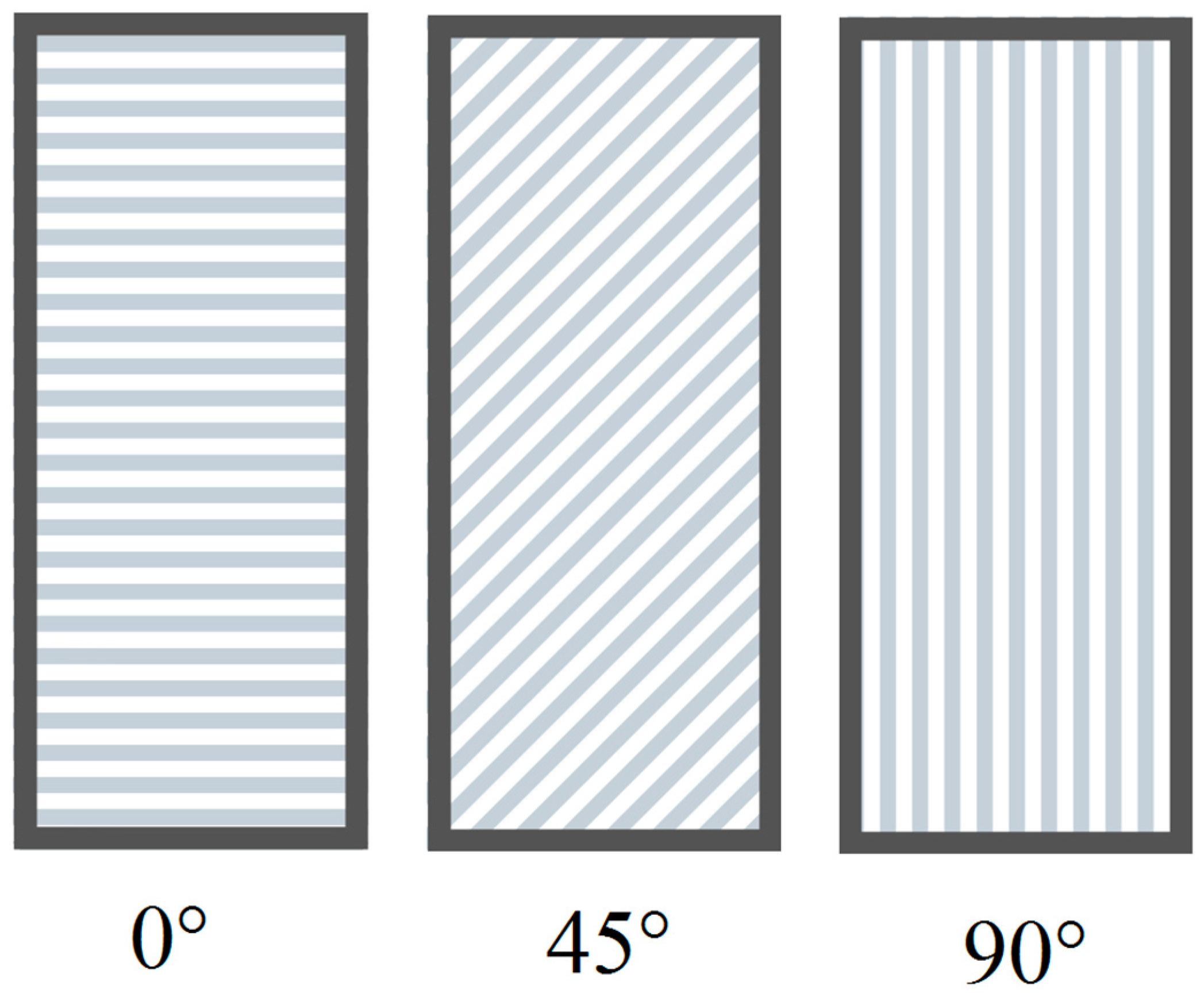
5.1. Build Orientation
5.2. Process Parameters
6. Post-Processing Strategies
6.1. Stress Relieving
6.2. Surface Finishing
7. Summary
- PBF-manufactured parts are characterized by an anisotropic γ-phase (face-centered cubic (fcc)) and ε-phase (hexagonal close-packed (hcp)). The microstructure, roughness and properties of the samples depend on build orientation. Parts built at 0° were characterized by the worst mechanical properties.
- Basic parameters, such as the laser power, scanning speed, laser beam size and layer thickness, are connected and they influence the density of the melted material. These parameters determine the material properties. In the SLM processes, energy input values above 0.36 J/s result in reduced sample density. The optimized range of laser energy density (LED) for Co28Cr6Mo SLM parts is 150–200 J mm−3.
- Post-processing heat treatment is considered necessary to ensure the reliable use of PFB-built parts in practical applications. Heat-treatment up to 1050 °C (even for six hours) is insufficient to eliminate anisotropy and residual stress. As heat-treatment temperatures increase from 750 °C to 1050 °C, homogenization also increases, compared with the as-built samples. Heating samples at 1150 °C for one hour causes the total homogenization of the sample’s microstructure.
- Optimization of the heat-treatment conditions for improving the mechanical properties (especially fatigue properties) remains a major challenge in SLM.
- Surface finishing of PFB-built parts is necessary.
Author Contributions
Funding
Conflicts of Interest
References
- Myszka, D.; Skrodzki, M. Comparison of Dental Prostheses Cast and Sintered by SLM from Co-Cr-Mo-W Alloy. Arch. Foundry Eng. 2016, 16, 201–207. [Google Scholar] [CrossRef] [Green Version]
- Craig, R.G. Materiały Stomatologiczne, 12th ed.; Powers, J.M., Sakaguchi, R.L., Shaw, H., Shaw, J.G., Eds.; Edra Urban and Partner: Wrocław, Poland, 2008; ISBN 9780323081085. [Google Scholar]
- Anusavice, K.; Shen, C.; Rawls, H.R. Phillips’ Science of Dental Materials, 12th ed.; Saunders: St. Louis, MO, USA, 2012. [Google Scholar]
- Antanasova, M.; Kocjan, A.; Kovač, J.; Žužek, B.; Jevnikar, P. Influence of thermo-mechanical cycling on porcelain bonding to cobalt–chromium and titanium dental alloys fabricated by casting, milling, and selective laser melting. J. Prosthodont. Res. 2018, 62, 184–194. [Google Scholar] [CrossRef]
- Reclaru, L.; Ardelean, L.C. Current Alternatives for Processing CoCr Dental Alloys Lucien; Elsevier Inc.: Cambridge, MA, USA, 2018; Volume 1–3, ISBN 9780128051443. [Google Scholar]
- Ferraiuoli, P.; Taylor, J.C.; Martin, E.; Fenner, J.W.; Narracott, A.J. The accuracy of 3D optical reconstruction and additive manufacturing processes in reproducing detailed subject-specific anatomy. J. Imaging 2017, 3, 45. [Google Scholar] [CrossRef]
- Hasan, H.A.; Alam, M.K.; Yusof, A.; Matsuda, S.; Shoumura, M.; Osuga, N. Accuracy of three dimensional CT craniofacial measurements using mimics and InVesalius software programs. J. Hard Tissue Biol. 2016, 25, 219–224. [Google Scholar] [CrossRef] [Green Version]
- Haleem, A.; Javaid, M. 3D scanning applications in medical field: A literature-based review. Clin. Epidemiol. Glob. Health 2019, 7, 199–210. [Google Scholar] [CrossRef] [Green Version]
- Javaid, M.; Haleem, A.; Kumar, L. Current status and applications of 3D scanning in dentistry. Clin. Epidemiol. Glob. Health 2019, 7, 228–233. [Google Scholar] [CrossRef] [Green Version]
- Strub, J.R.; Rekow, E.D.; Witkowski, S. Computer-aided design and fabrication of dental restorations: Current systems and future possibilities. J. Am. Dent. Assoc. 2006, 137, 1289–1296. [Google Scholar] [CrossRef]
- Sahasrabudhe, H.; Bose, S.; Bandyopadhyay, A. Laser-Based Additive Manufacturing Processes. In Advances in Laser Materials Processing; Lawrence, J., Ed.; Woodhead Publishing: Coventry, UK, 2018; pp. 507–539. ISBN 9780081012529. [Google Scholar]
- Han, X.; Sawada, T.; Schille, C.; Schweizer, E.; Scheideler, L.; Geis-Gerstorfer, J.; Rupp, F.; Spintzyk, S. Comparative analysis of mechanical properties and metal-ceramic bond strength of Co-Cr dental alloy fabricated by different manufacturing processes. Materials (Basel) 2018, 11, 1801. [Google Scholar] [CrossRef] [Green Version]
- Egea, A.J.S.; Martynenko, V.; Krahmer, D.M.; de Lacalle, L.N.L.; Benítez, A.; Genovese, G. On the cutting performance of segmented diamond blades when dry-cutting concrete. Materials (Basel) 2018, 11, 264. [Google Scholar] [CrossRef] [Green Version]
- Chhaya, M.P.; Poh, P.S.P.; Balmayor, E.R.; Van Griensven, M.; Schantz, J.T.; Hutmacher, D.W. Additive manufacturing in biomedical sciences and the need for definitions and norms. Expert Rev. Med. Devices 2015, 12, 537–543. [Google Scholar] [CrossRef]
- Singh, A.V.; Dad Ansari, M.H.; Wang, S.; Laux, P.; Luch, A.; Kumar, A.; Patil, R.; Nussberger, S. The adoption of three-dimensional additive manufacturing from biomedical material design to 3D organ printing. Appl. Sci. 2019, 9, 811. [Google Scholar] [CrossRef] [Green Version]
- Dobrzański, L.A.; Dobrzański, L.B. Dentistry 4.0 concept in the design and manufacturing of prosthetic dental restorations. Processes 2020, 8, 525. [Google Scholar] [CrossRef]
- Ngo, T.D.; Kashani, A.; Imbalzano, G.; Nguyen, K.T.Q.; Hui, D. Additive manufacturing (3D printing): A review of materials, methods, applications and challenges. Compos. Part B Eng. 2018, 143, 172–196. [Google Scholar] [CrossRef]
- Dikova, T. Properties of Co-Cr Dental Alloys Fabricated Using Additive Technologies. In Biomaterials in Regenerative Medicine; Dobrzański, L.A., Ed.; IntechOpen: London, UK, 2018; pp. 141–159. [Google Scholar]
- Revilla-León, M.; Özcan, M. Additive Manufacturing Technologies Used for 3D Metal Printing in Dentistry. Curr. Oral Health Rep. 2017, 4, 201–208. [Google Scholar] [CrossRef] [Green Version]
- Oliveira, T.T.; Reis, A.C. Fabrication of dental implants by the additive manufacturing method: A systematic review. J. Prosthet. Dent. 2019, 122, 270–274. [Google Scholar] [CrossRef]
- Okazaki, Y.; Ishino, A.; Higuchi, S. Chemical, physical, and mechanical properties and microstructures of laser-sintered Co-25Cr-5Mo-5W (SP2) and W-Free Co-28Cr-6Mo alloys for dental applications. Materials (Basel) 2019, 12, 4039. [Google Scholar] [CrossRef] [Green Version]
- Gabor, A.-G.; Zaharia, C.; Stan, A.T.; Gavrilovici, A.M.; Negruțiu, M.-L.; Sinescu, C. Digital Dentistry—Digital Impression and CAD/CAM System Applications. J. Interdiscip. Med. 2017, 2, 54–57. [Google Scholar] [CrossRef] [Green Version]
- Revilla-León, M.; Klemm, I.M.; García-Arranz, J.; Özcan, M. 3D Metal Printing–Additive Manufacturing Technologies for Frameworks of Implant- Borne Fixed Dental Prosthesis. Eur. J. Prosthodont. Restor. Dent. 2017, 25, 143–147. [Google Scholar] [CrossRef]
- Beaman, J.J.; Deckard, C.R. Selective Laser Sinterng with Assisted Powder Handlng. U.S. Patent 4,938,816, 3 July 1990. [Google Scholar]
- Höganäs, A.B. Höganäs Handbook for Sintered Components. Available online: https://www.hoganas.com/globalassets/download-media/sharepoint/handbooks---all-documents/handbook-2_production_of_sintered_components_december_2013_0675hog_interactive.pdf. (accessed on 20 June 2020).
- Anestiev, L.A.; Froyen, L. Model of the primary rearrangement processes at liquid phase sintering and selective laser sintering due to biparticle interactions. J. Appl. Phys. 1999, 86, 4008–4017. [Google Scholar] [CrossRef]
- Alageel, O.; Wazirian, B.; Almufleh, B.; Tamimi, F. Fabrication of Dental Restorations Using Digital Technologies: Techniques and Materials. In Digital Restorative Dentistry: A Guide to Materials, Equipment, and Clinical Procedures; Tamimi, F., Hirayama, H., Eds.; Springer: Cham, Switzerland, 2019; pp. 55–91. [Google Scholar]
- Vandenbroucke, B.; Kruth, J.P. Selective laser melting of biocompatible metals for rapid manufacturing of medical parts. Rapid Prototyp. J. 2007, 13, 196–203. [Google Scholar] [CrossRef]
- Yap, C.Y.; Chua, C.K.; Dong, Z.L.; Liu, Z.H.; Zhang, D.Q.; Loh, L.E.; Sing, S.L. Review of selective laser melting: Materials and applications. Appl. Phys. Rev. 2015, 2, 1–21. [Google Scholar] [CrossRef]
- Murr, L.E.; Gaytan, S.M.; Ramirez, D.A.; Martinez, E.; Hernandez, J.; Amato, K.N.; Shindo, P.W.; Medina, F.R.; Wicker, R.B. Metal Fabrication by Additive Manufacturing Using Laser and Electron Beam Melting Technologies. J. Mater. Sci. Technol. 2012, 28, 1–14. [Google Scholar] [CrossRef]
- Singh, R.; Singh, S.; Hashmi, M.S.J. Implant Materials and Their Processing Technologies; Elsevier Ltd.: Amsterdam, The Netherlands, 2016; ISBN 9780128035818. [Google Scholar]
- Wang, J.; Ren, J.; Liu, W.; Wu, X.; Gao, M.; Bai, P. Effect of Selective Laser Melting Process Parameters on Microstructure and Properties of Co-Cr Alloy. Materials (Basel) 2018, 11, 1546. [Google Scholar] [CrossRef] [PubMed] [Green Version]
- Szczurek, A. Struktura i własności stopów dentystycznych na bazie kobaltu stosowanych do wykonywania protez szkieletowych. Inżynieria Mater. 2013, XXXIV, 116–120. [Google Scholar]
- Mróz, A.; Jakubowicz, J.; Gierzyńska-dolna, M.; Wiśniewski, T.; Wendland, J. Wpływ technologii wytwarzania wyrobów ze stopu Co28Cr6Mo na ich właściwości fizyczne, mechaniczne i odporność korozyjną. Inżynieria Mater. 2015, 1, 2–8. [Google Scholar] [CrossRef]
- Fatemi, A.; Molaei, R.; Fatemi, A. Fatigue Design with Additive Manufactured Metals: Issues to Consider and Perspective for Future Research. Procedia Eng. 2018, 213, 5–16. [Google Scholar] [CrossRef]
- Kok, Y.; Tan, X.P.; Wang, P.; Nai, M.L.S.; Loh, N.H.; Liu, E.; Tor, S.B. Anisotropy and heterogeneity of microstructure and mechanical properties in metal additive manufacturing: A critical review. Mater. Des. 2017, 139, 565–586. [Google Scholar] [CrossRef]
- Kajima, Y.; Takaichi, A.; Nakamoto, T.; Kimura, T.; Kittikundecha, N.; Tsutsumi, Y.; Nomura, N.; Kawasaki, A.; Takahashi, H.; Hanawa, T.; et al. Effect of adding support structures for overhanging part on fatigue strength in selective laser melting. J. Mech. Behav. Biomed. Mater. 2018, 78, 1–9. [Google Scholar] [CrossRef]
- Harun, W.; Sharuzi, W.; Kadirgama, K.; Samykano, M.; Ramasamy, D.; Ahmad, I.; Moradi, M. Mechanical behavior of selective laser melting-produced metallic biomaterials. In Mechanical Behavior of Biomaterials; Davim, J.P., Ed.; Woodhead Publishing: Cambridge, UK, 2019; pp. 101–116. ISBN 9780081021743. [Google Scholar]
- Shifeng, W.; Shuai, L.; Qingsong, W.; Yan, C.; Sheng, Z.; Yusheng, S. Effect of molten pool boundaries on the mechanical properties of selective laser melting parts. J. Mater. Process. Technol. 2014, 214, 2660–2667. [Google Scholar] [CrossRef]
- Hanzl, P.; Zetek, M.; Bakša, T.; Kroupa, T. The influence of processing parameters on the mechanical properties of SLM parts. Procedia Eng. 2015, 100, 1405–1413. [Google Scholar] [CrossRef] [Green Version]
- Takaichi, A.; Suyalatu; Nakamoto, T.; Joko, N.; Nomura, N.; Tsutsumi, Y.; Migita, S.; Doi, H.; Kurosu, S.; Chiba, A.; et al. Microstructures and mechanical properties of Co-29Cr-6Mo alloy fabricated by selective laser melting process for dental applications. J. Mech. Behav. Biomed. Mater. 2013, 21, 67–76. [Google Scholar] [CrossRef] [PubMed]
- Sun, S.H.; Koizumi, Y.; Kurosu, S.; Li, Y.P.; Matsumoto, H.; Chiba, A. Build direction dependence of microstructure and high-temperature tensile property of Co-Cr-Mo alloy fabricated by electron beam melting. Acta Mater. 2014, 64, 154–168. [Google Scholar] [CrossRef]
- Kajima, Y.; Takaichi, A.; Nakamoto, T.; Kimura, T.; Yogo, Y.; Ashida, M.; Doi, H.; Nomura, N.; Takahashi, H.; Hanawa, T.; et al. Fatigue strength of Co-Cr-Mo alloy clasps prepared by selective laser melting. J. Mech. Behav. Biomed. Mater. 2016, 59, 446–458. [Google Scholar] [CrossRef] [PubMed]
- Øilo, M.; Nesse, H.; Lundberg, O.J.; Gjerdet, N.R. Mechanical properties of cobalt-chromium 3-unit fi xed dental prostheses fabricated by casting, milling, and additive manufacturing. J. Prosthet. Dent. 2015, 120, 1–7. [Google Scholar] [CrossRef]
- Kittikundecha, N.; Kajima, Y.; Takaichi, A.; Htoot, H.; Cho, W. Fatigue properties of removable partial denture clasps fabricated by selective laser melting followed by heat treatment. J. Mech. Behav. Biomed. Mater. 2019, 98, 79–89. [Google Scholar] [CrossRef] [PubMed]
- Frazier, W.E. Metal Additive Manufacturing: A Review. J. Mater. Eng. Perform. 2014, 23, 1917–1928. [Google Scholar] [CrossRef]
- Averyanova, M.; Bertrand, P.; Verquin, B. Manufacture of Co-Cr dental crowns and bridges by selective laser Melting technology: This paper presents the successful application of the selective laser melting technology in dental frameworks manufacturing from Co-Cr alloy using Phenix PM 100T dental. Virtual Phys. Prototyp. 2011, 6, 179–185. [Google Scholar] [CrossRef]
- Gu, D.; Shi, Q.; Lin, K.; Xi, L. Microstructure and performance evolution and underlying thermal mechanisms of Ni-based parts fabricated by selective laser melting. Addit. Manuf. 2018, 22, 265–278. [Google Scholar] [CrossRef]
- Song, C.; Yang, Y.; Wang, Y.; Wang, D.; Yu, J. Research on rapid manufacturing of Co-Cr-Mo alloy femoral component based on selective laser melting. Int. J. Adv. Manuf. Technol. 2014, 75, 445–453. [Google Scholar] [CrossRef]
- Lu, Y.; Wu, S.; Gan, Y.; Li, J.; Zhao, C.; Zhuo, D.; Lin, J. Investigation on the microstructure, mechanical property and corrosion behavior of the selective laser melted Co-Cr-W alloy for dental application. Mater. Sci. Eng. C 2015, 49, 517–525. [Google Scholar] [CrossRef]
- Tonelli, L.; Fortunato, A.; Ceschini, L. Co-Cr alloy processed by Selective Laser Melting (SLM): Effect of Laser Energy Density on microstructure, surface morphology, and hardness. J. Manuf. Process. 2020, 52, 106–119. [Google Scholar] [CrossRef]
- Popovich, V.A.; Borisov, E.V.; Popovich, A.A.; Su, V.S.; Masaylo, D.V.; Alzina, L. Functionally graded Inconel 718 processed by additive manufacturing: Crystallographic texture, anisotropy of microstructure and mechanical properties. Mater. Des. 2016, 114, 441–449. [Google Scholar] [CrossRef]
- Xie, W.; Zheng, M.; Wang, J.; Li, X. The effect of build orientation on the microstructure and properties of selective laser melting Ti-6Al-4V for removable partial denture clasps. J. Prosthet. Dent. 2020, 123, 163–172. [Google Scholar] [CrossRef] [PubMed] [Green Version]
- Ishida, B.K.; Nlshizawa, T. The Co-Cr (Cobalt-Chromium) System. Bull. Alloy Phase Diagrams 1990, 11, 357–370. [Google Scholar] [CrossRef]
- Yan, X.; Lin, H.; Wu, Y.; Bai, W. Effect of two heat treatments on mechanical properties of selective-laser-melted Co-Cr metal-ceramic alloys for application in thin removable partial dentures. J. Prosthet. Dent. 2018, 119, 1028.e1–1028.e6. [Google Scholar] [CrossRef] [PubMed]
- Instructions for Use EOS CobaltChrome SP2. Available online: http://webcache.googleusercontent.com/search?q=cache:ltA3cJm7RRAJ:ip-saas-eos-cms.s3.amazonaws.com/public/32ff6c9b7964c1c9/7c73a9305d8007c47dec2e65196f09e5/EOS_CobaltChrome_SP2_en.pdf+&cd=1&hl=pl&ct=clnk&gl=pl&lr=lang_en%7Clang_pl&client=firefox-b-d (accessed on 6 May 2020).
- Material Data Sheet EOS CobaltChrome MP1. Available online: https://webcache.googleusercontent.com/search?q=cache:FU463ZFb7_cJ:https://ip-saas-eos-cms.s3.amazonaws.com/public/4b839242298b3d77/721463526ca053889c9784ec989f3c88/EOS_CobaltChrome_MP1_en.pdf+&cd=1&hl=pl&ct=clnk&gl=pl&lr=lang_en%7Clang_pl&client=firefox- (accessed on 6 May 2020).
- Instructions for Use Renishaw Co-Cr DG1. Available online: http://webcache.googleusercontent.com/search?q=cache:_eQiV5qm-rMJ:resources.renishaw.com/en/download/instructions-for-use-cocr-dg1--96951+&cd=1&hl=pl&ct=clnk&gl=pl&lr=lang_en%7Clang_pl&client=firefox-b-d (accessed on 6 May 2020).
- Béreš, M.; Silva, C.C.; Sarvezuk, P.W.C.; Wu, L.; Antunes, L.H.M.; Jardini, A.L.; Feitosa, A.L.M.; Žilková, J.; de Abreu, H.F.G.; Filho, R.M. Mechanical and phase transformation behaviour of biomedical Co-Cr-Mo alloy fabricated by direct metal laser sintering. Mater. Sci. Eng. A 2018, 714, 36–42. [Google Scholar] [CrossRef]
- Takaichi, A.; Kajima, Y.; Kittikundecha, N.; Linn, H.; Htoot, H.; Cho, W.; Hanawa, T.; Yoneyama, T.; Wakabayashi, N. Effect of heat treatment on the anisotropic microstructural and mechanical properties of Co-Cr-Mo alloys produced by selective laser melting. J. Mech. Behav. Biomed. Mater. 2020, 102, 103496. [Google Scholar] [CrossRef]
- Kajima, Y.; Takaichi, A.; Kittikundecha, N.; Nakamoto, T.; Kimura, T.; Nomura, N.; Kawasaki, A.; Hanawa, T.; Takahash, H.; Wakabayashi, N. Effect of heat-treatment temperature on microstructures and mechanical properties of Co-Cr-Mo alloys fabricated by selective laser melting. Mater. Sci. Eng. A 2018, 726, 21–31. [Google Scholar] [CrossRef]
- Sing, S.L.; Huang, S.; Yeong, W.Y. Effect of solution heat treatment on microstructure and mechanical properties of laser powder bed fusion produced cobalt-28chromium-6molybdenum. Mater. Sci. Eng. A 2020, 769, 138511. [Google Scholar] [CrossRef]
- Seki, E.; Kajima, Y.; Takaichi, A.; Kittikundecha, N.; Htoot, H.; Cho, W.; Linn, H.; Doi, H.; Hanawa, T.; Wakabayashi, N. Effect of heat treatment on the microstructure and fatigue strength of Co-Cr-Mo alloys fabricated by selective laser melting. Mater. Lett. 2019, 245, 53–56. [Google Scholar] [CrossRef]
- Doherty, R.D.; Hughes, D.A.; Humphreys, F.J.; Jonas, J.J.; Juul Jensen, D.; Kassner, M.E.; King, W.E.; McNelley, T.R.; McQueen, H.J.; Rollett, A.D. Current issues in recrystallization: A review. Mater. Sci. Eng. A 1997, 238, 219–274. [Google Scholar] [CrossRef] [Green Version]
- Liu, F.; Lin, X.; Yang, G.; Song, M.; Chen, J.; Huang, W. Microstructure and residual stress of laser rapid formed Inconel 718 nickel-base superalloy. Opt. Laser Technol. 2011, 43, 208–213. [Google Scholar] [CrossRef]
- Song, B.; Dong, S.; Liu, Q.; Liao, H.; Coddet, C. Vacuum heat treatment of iron parts produced by selective laser melting: Microstructure, residual stress and tensile behavior. Mater. Des. 2014, 54, 727–733. [Google Scholar] [CrossRef]
- Bedolla-Gil, Y.; Hernandez-Rodriguez, M.A.L. Tribological Behavior of a Heat-Treated Cobalt-Based Alloy. J. Mater. Eng. Perform. 2013, 22, 541–547. [Google Scholar] [CrossRef]
- Montero-Ocampo, C.; Talavera, M.; Lopez, H. Effect of Alloy Preheating on the Mechanical Properties of As-Cast Co-Cr-Mo-C Alloys. Metall. Mater. Trans. A 1999, 30, 611–620. [Google Scholar] [CrossRef]
- Bhaduri, A. Creep and Stress Repture. In Mechanical Properties and Working of Metals and Alloys; Springer: Singapore, 2018; pp. 257–314. [Google Scholar]
- Mancha, H.; Carranza, E.; Escalante, J.I.; Mendoza, G.; Mendez, M.; Cepeda, F.; Valdes, E. M 23 C 6 Carbide Dissolution Mechanisms during Heat Treatment of ASTM F-75 Implant Alloys. Metall. Mater. Trans. A 2001, 32A, 979. [Google Scholar] [CrossRef]
- Ramírez-Vidaurri, L.E.; Castro-Román, M.; Herrera-Trejo, M.; García-López, C.V.; Almanza-Casas, E. Cooling rate and carbon content effect on the fraction of secondary phases precipitate in as-cast microstructure of ASTM F75 alloy. J. Mater. Process. Technol. 2009, 209, 1681–1687. [Google Scholar] [CrossRef]
- Hassani, F.Z.; Ketabchi, M.; Bruschi, S.; Ghiotti, A. Effects of carbide precipitation on the microstructural and tribological properties of Co-Cr-Mo-C medical implants after thermal treatment. J. Mater. Sci. 2016, 51, 4495–4508. [Google Scholar] [CrossRef]
- Alvarez-Vera, M.; Hernandez-Rodriguez, A.; Hernandez-Rodriguez, M.A.L.; Juárez Hernández, A.; Benavides-Treviño, J.R.; García-Duarte, J. Effect of cooling rate during solidification on the hard phases of M23C6-type of cast Co-Cr-Mo alloy. Metalurgija 2016, 55, 382–384. [Google Scholar]
- Guoqing, Z.; Junxin, L.; Xiaoyu, Z.; Jin, L.; Anmin, W. Effect of Heat Treatment on the Properties of Co-Cr-Mo Alloy Manufactured by Selective Laser Melting. J. Mater. Eng. Perform. 2018, 27, 2281–2287. [Google Scholar] [CrossRef]
- Lu, Y.; Wu, S.; Gan, Y.; Zhang, S.; Guo, S.; Lin, J.; Lin, J. Microstructure, mechanical property and metal release of As-SLM Co-Cr-W alloy under different solution treatment conditions. J. Mech. Behav. Biomed. Mater. 2016, 55, 179–190. [Google Scholar] [CrossRef] [PubMed]
- Yung, K.C.; Wang, W.J.; Xiao, T.Y.; Choy, H.S.; Mo, X.Y.; Cai, Z.X.; Wang, W.J.; Xiao, T.Y.; Choy, H.S.; Mo, X.Y.; et al. Laser polishing of additive manufactured Co-Cr components for controlling their wettability characteristics. Surf. Coat. Technol. 2018, 351, 89–98. [Google Scholar] [CrossRef]
- Yung, K.C.; Xiao, T.Y.; Choy, H.S.; Wang, W.J.; Cai, Z.X. Laser polishing of additive manufactured Co-Cr alloy components with complex surface geometry. J. Mater. Process. Technol. 2018, 262, 53–64. [Google Scholar] [CrossRef]
- Wang, W.J.; Yung, K.C.; Choy, H.S.; Xiao, T.Y.; Cai, Z.X. Effects of laser polishing on surface microstructure and corrosion resistance of additive manufactured Co-Cr alloys. Appl. Surf. Sci. 2018, 443, 167–175. [Google Scholar] [CrossRef]
- Manea, A.; Bran, S.; Baciut, M.; Armencea, G.; Pop, D.; Berce, P.; Vodnar, D.-C.; Hedesiu, M.; Dinu, C.; Petrutiu, A.; et al. Sterilization protocol for porous dental implants made by Selective Laser Melting. Dent. Med. 2018, 91, 452–457. [Google Scholar] [CrossRef] [PubMed]


| Process | Technology | Ref. |
|---|---|---|
| Digital impression | It is a non-invasive method to obtain a virtual model of the hard and soft tissue of the patient’s oral cavity. This involves the use of an intraoral scanner which records a series of snapshots of the oral cavity of the patient. | [22] |
| Prosthetic designing | Scanner data are evaluated and processed by the dental laboratory using special software. The digital prosthetic model is individually tailored to the patient. | [22] |
| Manufacturing process | Milling (subtractive manufacturing): a prepared prosthetic design is mechanically cut from a metal block. This process is controlled by software. Milling units in the last decade were optimized—large angulations of the fourth and fifth axes (>30 degrees), dry or wet grinding. | [5] |
| Sintering (subtractive manufacturing): technology developed by Amann Girrbach. The prepared prosthetic is mechanically cut from metal blanks with a wax-like texture. The process is controlled by software. The blocks are made from unsintered metal powder held together by a binder. After the milling process, the structure is subjected to sintering in a special furnace. | ||
| Powder bed fusion (PBF, additive manufacturing): the prepared prosthetic is formed by the thermal consolidation of a metal powder (layer by layer). The process is controlled by software. Selective laser sintering (SLS), selective laser melting (SLM) and electron beam melting (EBM) are three methods classified as PBF. |
| Brand | PBF System | Chemical Composition (wt.%) |
|---|---|---|
| EOS CoCr SP2 (DA) | DMLS (direct metal laser solidification) = SLM | Co: 63.8; Cr: 24.7; Mo: 5.1; W: 5.4; Si: 1.0; Fe: ≤0.50; Mn: ≤0.10 Free of Ni, Be, Cd and Pb |
| EOS CoCr MP1(MA) | DMLS (direct metal laser solidification) = SLM | Co: 60–65; Cr: 26–30; Mo: 5–7; Si: ≤1.0; Mn: ≤1.0; Fe: ≤0.75; C: ≤0.16; Ni: ≤0.10 |
| Renishaw CoCr DG1(DA) | SLM | Co: 63.9; Cr: 24.7; Mo: 5.0; W: 5.4; Si: 1.0 Free of Ni, Be, Cd and Pb |
| SLM Solutions MediDent (DA) | SLM | Co: Balance; Cr: 22.7–26.7; Mo: 4–6; W: 4.4–6.4; Si: 2; Fe: 0.5; Mn: 0.10; C: 0.02; Ni: 0.10; B, S: 0.10 |
| SLM Solutions CoCr28Mo6 (MA) | SLM | Co: Balance; Cr: 27–30; Mo: 5–7; W: 0.20; Si: 1; Al: 0.10; Fe: 0.75; Mn: 1; C: 0.35; N: 0.25; Ni: 0.5 Ti: 0.1; B, S: 0.01 |
| 3D systems LaserForm CoCr(A,B,C) ASTM F75(DA and MA) | SLM | Co Bal., Cr 28.00–30.00, Mo 5.00–6.00, Ni 0.00–0.10, Fe 0.00–0.50, C 0.00–0.02, Si 0.00–1.00, Mn 0.00–1.00, Cd 0.00–0.02, Be 0.00–0.02, Pb 0.00–0.02 |
| Concept Laser Remanium star CL | DMLM (direct metal laser melting) | Co: 60.5; Cr: 28; W: 9; Si: 1.5; Other elements <1: Mn, N, Nb, Fe. free from nickel, beryllium and gallium |
| BEGO Wirobond C+ | SLM | Co: 63.9; Cr: 24.7; W: 5.4; Mo: 5.0; Si: <1 |
| Scheftner Starbond COS | SLM | Co: 59; Cr: 25; W: 9.5; Mo: 3.5; Si: 1; C,Fe,Mn,N: <1% |
| Scheftner Starbond Easy 30 | SLM | Co: 61; Cr: 27.5; W: 8.5; Si: 1,6; C,Fe,Mn: <1 |
| Property | OS SP2 | EOS MP1 | Renisaw DG1 | SLM MediDent | SLM CoCr28Mo6 | LaserForm CoCr (B) | Concept Laser Remanium Star CL | BEGO Wirobond C+ | Scheftner Starbond COS | Scheftner Starbond Easy 30 |
|---|---|---|---|---|---|---|---|---|---|---|
| Density (g/cm3) | 8.5 | 8.3 | 8.3 | NA | NA | 8.3 | 8.6 | 8.6 | 8.8 | 8.5 |
| Tensile strength (MPa) | 1350 | 1100 | 1076 | 1415 | 1215 | 1445 +/− 50 | 1030 | 1315 | 990–1250 | 1090 |
| Elongation at break (%) | 3 | Min. 20 | 2.7 | 4 | 21 | 34 +/− 6 | 10 | 2–10 | 15 | |
| Young’s Modulus (GPa) | approx. 200 | 200 | 224 | 245 | 205 | 230 +/− 40 | 230 | 215 | 195–200 | 225 |
| Hardness | 420 HV | approx. 35–45 HRC | 430 HV | NA/375 HV as built | 385 HV | 26 +/− 5 Rockwell C | NA | NA | 345–490 HV 10 | 425 HV 10 |
| Coefficient of thermal expansion | 14.3 × 10⁻⁶ m/m °C | 13.6 × 10⁻⁶ m/m °C–15.1 × 10⁻⁶ m/m °C | 14.1 | NA | NA | 14 | 14.1 (500 °C) | 14.3 (RT-500 °C) 14.5 (RT-600 °C) | 14.4 (600 °C) | 14.5 (500 °C) 14.7(600 °C) |
| Melting interval (°C) | 1410–1450 | 1350–1430 | 1375–1405 | NA | NA | 1350–1430 | 1320–1420 | 1380–1420 | 1305–1400 | 1310–1410 |
| Procedure | Note | References |
|---|---|---|
| Under an argon atmosphere. 1. Heat furnace from room temperature to 450 °C in 60 min and hold at this temperature for 45 min. 3. Heat furnace to 750 °C in 45 min and hold at this temperature for 60 min (holding temperature and time tolerance inside the box: 740 °C +/− 10 °C, 60 minutes +/− 20 min). 5. Switch off the heating. 6. When temperature has dropped down to approx. 600 °C, open the furnace door. 7. When furnace has cooled down to approx. 300 °C, remove the protective gas box from furnace and shut down the argon flow. | Instructions for use material: EOS CobaltChrome SP2. Longer holding time, utilization of higher stress-relieving temperature or forced cooling may lead to increased brittleness of restorations. | [56] |
| Post-process stress relieving at 1150 °C for six hours. | Instructions for use material: EOS CoCr MP1 for medical applications. | [57] |
| Under an argon atmosphere. Hold at 750 °C temperature for 60 min and allowed to cool naturally. | Instructions for use Renishaw CoCr DG1. | [58] |
| I. First heating process 1. Heat furnace from room temperature to 500 °C (a ramp rate of 8 °C/min) and hold at this temperature for 45 min. 2. Heat furnace to 880 °C in 60 min, and hold at this temperature for 60 min. 3. Switch off the heating. 4. When temperature has dropped down to approx. 600 °C, open the furnace door. 5. Remove specimens from the furnace when the temperature has dropped to 300 °C. II. Second heating process 1. Heat furnace from room temperature to 1100 °C (a ramp rate of 8 °C/min) and hold at this temperature for 30 min. 2. Switch off the heating. 3. When temperature has dropped down to approx. 600 °C, open the furnace door. 4. Remove specimens from the furnace when the temperature has dropped to 300 °C. | Heat treated SLM-fabricated samples (at 880 °C and 1100 °C) exhibited mechanical properties that exceeded the minimum requirements according to ISO standard (ISO 22674:2016.8). The heat treatment at 1100 °C was more efficient for relieving residual stress. | [55] |
| 1. Heat furnace from room temperature to 1150 °C and hold at this temperature for 60 min. 2. Cool samples in water (water quenching) 3. Half of the samples were additionally subjected to isothermal heat treatment at 800 °C for four hours 4. Cool samples in water (water quenching) | The elimination of dendritic microstructure and micro-segregation was achieved after heat treatment at 1150 °C. Increased tensile strength and yield stress were achieved by isothermal heat treatment at 800 °C and water quenching due to a diffusely formed hcp ε phase, finely distributed in the fcc γ matrix. Crack initiation and propagation occur preferentially at the ε martensite. | [59] |
| Under an argon atmosphere. 1. Heat furnace from room temperature to 750, 900, 1050, or 1150 °C (a ramp rate of 60 °C/min) and hold at the specified temperature for six hours. 2. Switch off the heating. 3. When temperature has dropped down to approx. 300 °C, open the furnace door. | Heat treatment at temperatures below 1050 °C was insufficient to eliminate the anisotropic columnar grains, fiber texture and residual stress. Recrystallization via heat treatment at 1150 °C homogenizes the microstructure, eliminate residual stress and enables reduction of the anisotropic mechanical properties. Increasing the heat-treatment temperature from 750 °C to 1150 °C increased the ductility of the alloy and decreased its 0.2% offset yield strength and Vickers hardness. | [60,61] |
| The three heat treatment cycles were used: I. One hour at 1220 °C; II. Four hours preheating at 815 °C and then two hours at 1220 °C; III. Four hours at 1220 °C. Rapid quenching in water at room temperature was done at the end of preheating and solution treatment. | After heat treatment, both the ultimate tensile strength and yield strength of SLM CoCrMo decreased due to the homogenization of microstructure and texture. The microstructure analysis concluded carbides formation. | [62] |
| Under an argon atmosphere. 1. Heat furnace from room temperature to 600 °C (a ramp rate of 10 °C/min) and hold at this temperature for 30 minutes. 2. Heat furnace to 1150 °C and hold at this temperature for one or six hours. 3. After one or six hours switch off the heating. 4. Cool samples slowly to room temperature in a furnace. | Heat treatment at 1150 °C for one and six hours allowed the homogenization of microstructure and texture. Higher fatigue strength was observed after 1 h treatment compared with control groups (as built 0° and 45° building angulations). Six hours heat treatment created large precipitates and a thick oxide layer associated with a decrease in fatigue strength. | [45,63] |
© 2020 by the authors. Licensee MDPI, Basel, Switzerland. This article is an open access article distributed under the terms and conditions of the Creative Commons Attribution (CC BY) license (http://creativecommons.org/licenses/by/4.0/).
Share and Cite
Konieczny, B.; Szczesio-Wlodarczyk, A.; Sokolowski, J.; Bociong, K. Challenges of Co–Cr Alloy Additive Manufacturing Methods in Dentistry—The Current State of Knowledge (Systematic Review). Materials 2020, 13, 3524. https://doi.org/10.3390/ma13163524
Konieczny B, Szczesio-Wlodarczyk A, Sokolowski J, Bociong K. Challenges of Co–Cr Alloy Additive Manufacturing Methods in Dentistry—The Current State of Knowledge (Systematic Review). Materials. 2020; 13(16):3524. https://doi.org/10.3390/ma13163524
Chicago/Turabian StyleKonieczny, Bartłomiej, Agata Szczesio-Wlodarczyk, Jerzy Sokolowski, and Kinga Bociong. 2020. "Challenges of Co–Cr Alloy Additive Manufacturing Methods in Dentistry—The Current State of Knowledge (Systematic Review)" Materials 13, no. 16: 3524. https://doi.org/10.3390/ma13163524