Free Vibration Analysis of Closed Moderately Thick Cross-Ply Composite Laminated Cylindrical Shell with Arbitrary Boundary Conditions


1
College of Mechanical and Electrical Engineering, Harbin Engineering University, Harbin 150001, China
2
State Key Laboratory of High Performance Complex Manufacturing, Central South University, Changsha 410083, China
3
Department of Automotive Engineering, Harbin Vocational & Technical College, Harbin 150001, China
*
Author to whom correspondence should be addressed.
Materials 2020, 13(4), 884; https://doi.org/10.3390/ma13040884
Submission received: 26 December 2019
/
Revised: 11 February 2020
/
Accepted: 14 February 2020
/
Published: 17 February 2020
Abstract
:A semi-analytic method is adopted to analyze the free vibration characteristics of the moderately thick composite laminated cylindrical shell with arbitrary classical and elastic boundary conditions. By Hamilton’s principle and first-order shear deformation theory, the governing equation of the composite shell can be established. The displacement variables are transformed into the wave function forms to ensure the correctness of the governing equation. Based on the kinetic relationship between the displacement variables and force resultants, the final equation associated with arbitrary boundary conditions is established. The dichotomy method is conducted to calculate the natural frequencies of the composite shell. For verifying the correctness of the present method, the results by the present method are compared with those in the pieces of literatures with various boundary conditions. Furthermore, some numerical examples are calculated to investigate the effect of several parameters on the composite shell, such as length to radius ratios, thickness to radius ratios and elastic restrained constants.
1. Introduction
With the rapid development of the industry, composite laminated materials are increasingly used. The composite laminated cylindrical shell is one of the principal structural components and is widely used in various engineering applications, such as naval equipment, vehicle engineering, aerospace, and basic industries. In the past few decades, the dynamic analysis of composite shells has made considerable progress. People are paying more and more attention to developing more accurate and effective mathematical models and analyzing their dynamic behavior. Some researchers have proposed some of the classical and improved theories, also, different calculation methods are developed. The extensive researches are evolved by Lessia [1], Qatu [2,3,4,5], Reddy [6], Carrera [7,8], Ye [9] and others [10,11,12].
According to the previously reported studies, there are three main shell theories that are usually known: classical shell theory (CST) [13,14,15,16], first-order shear deformation shell theory (FSDST) [17,18,19,20,21] and higher-order shear deformation shell theory (HSDST) [22,23,24,25,26]. The classical shell theory is the basic theory, the transverse normal and shear deformations are ignored. Also, some theories are developed based on CST, such as Flügge’s theory and Donner–Mushtari’s theory. When anticipating the effects of transverse shear deformations, the FSDST is conducted. The transverse shear stiffness is corrected by the shear correction factor. HSDST analyzes the shell dynamic problem more precisely, but the amount of calculation is large. With continuous development in recent years, many researchers have conducted in-depth research on the dynamic analysis of the moderately thick composite laminated cylindrical shells. In this paper, some research statuses are listed. Alijani and Aghdam [27] proposed the Kantorovich method to investigate the moderately thick laminated cylindrical panels with several boundary conditions (i.e., F-F, C-C, and S-S). The loadings are set as uniform and sinusoidally distributed forms. Hosseini-Hashemi et al. [28] presented the state space method to study the free vibration characteristics of the rotating functionally graded circular cylindrical shell. The Sanders shear deformation theory, Coriolis, centrifugal and initial hoop tension effects are adopted to establish the motion equations. Sakka et al. [29] proposed the double Fourier series expansion method to analyze the free vibration characteristics of the moderately thick orthotropic cylindrical shell panels. The boundary condition is set as clamped and the Sanders kinematics is assembled to get the governing differential equations. Hao et al. [30] extended the isogeometric method [31] to study the buckling characteristics of the complex composite shells. Zhu et al. [32] conducted the modified Fourier series method to discuss the free vibration of the functionally graded open shells. The moderately thick shell forms are given as cylindrical, conical and spherical shells. Kurtaran [33] extended the Generalized Differential Quadrature (GDQ) method to study the transient characteristics of the moderately composite shallow shell. Maleki et al. [34] presented the GDQ method to investigate the static characteristics of moderately thick laminated cylindrical shell panels with different loadings and boundary conditions. The GDQ technique and Newmark’s plan are adopted to establish the governing equations. Fazilati and Ovesy [35] extended the spline method to discuss the parametric stability and instability region problem. The Koiter–Sanders theory is considered to express the linear strain terms when the shell structure is under harmonic in-plane loads. Tabiei and Simitses [36] analyzed the classical, first-order and higher-order shear deformation, the Donnell and Sanders type kinematics relations to describe the kinematic relations and equilibrium equations. Garcia et al. [37] investigated the effect of polycaprolactone nanofibers on the dynamic behavior of glass fiber reinforced polymer composites. Garcia et al. [38] conducted the influence of the inclusion of nylon nanofibers on the global dynamic behavior of glass fiber reinforced polymer (GFRP) composite laminates.
The wave based method (WBM) is a new analysis method to investigate the dynamic characteristics of the engineering structures. In recent years, some applications for WBM methods have gradually been developed. Yang et al. [39] analyzed the power flow of the plate structure by WBM. The results were compared with Finite element method (FEM) to validate the advantage of the present method. Koo et al. [40] proposed the WBM to discuss the semi-coupled structural–acoustic problem. He et al. [41] discussed the modeling acoustic problems and applied to the low-frequency applications. Also, the vibration characteristics of some engineering structures were extended by the WBM in engineering geometry applications, such as cylindrical shells with discontinuity in thickness [42], ring-stiffened cylindrical shells [43], composite laminated cylindrical shells [44], composite laminated shallow shells [45], cylindrical shells with non-uniform stiffener distribution [46], underwater cylindrical shells with bulkheads [47] and some coupled structures [48]. However, it can be seen that there is currently no relevant literature on the study of free vibration characteristics for moderately thick composite laminated cylindrical shells with arbitrary boundary conditions. Therefore, it is worthwhile to take advantage of the present method.
This paper aims to develop a new semi-analyzed method to investigate the free vibration characteristics of moderately thick composite laminated cylindrical shell with arbitrary boundary conditions. FSDST is adopted to describe the relationship between the displacement variables and transverse rotations. According to the Hamilton principle, the governing equation of the moderately thick composite laminated cylindrical shell is obtained. Transform the displacement variables into wave function forms to verify the motion governing equations. The total matrix is established according to boundary matrices that depend on arbitrary boundary conditions. To test and verify the free vibration characteristics of the moderately thick composite laminated cylindrical shell under arbitrary boundary conditions, the results by the present method are contrasted with the solutions in recent pieces of literature. Furthermore, some numerical examples are shown to discuss the effect of geometric parameters, stiffness constants and some conclusions are obtained. The advantage of this method is that it is easy to construct a global matrix, which is adapted to various boundary conditions, and has high calculation efficiency and high accuracy.
2. Theoretical Formulations
2.1. The Description of the Model
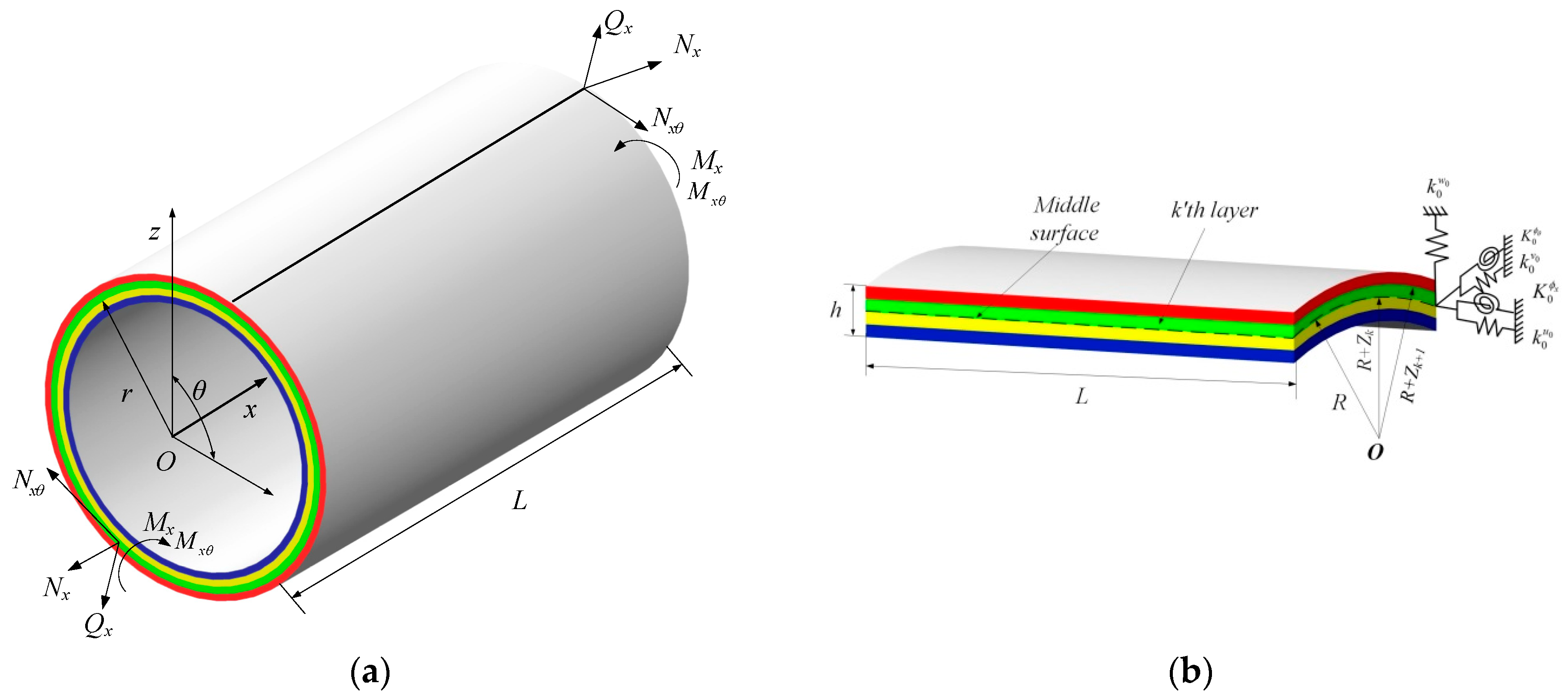
Consider the model in Figure 1, the moderately thick composite laminated cylindrical shell with general boundary conditions. L, R, and h denote the length, mean radius and thickness of the shell. The global coordinate (x, θ, z) are set, the x, θ and z axes are taken in the axial circumferential and radial directions. In the k’th layer, the included angle of the composite material and principle direction is defined as β. The distances from the top and bottom surfaces to the middle surface are defined as Zk+1 and Zk. The middle surface displacements of the composite shell are defined as u0, v0, and w0, their directions are set in the x, θ and z axes. The transverse rotations about the θ and x axes are represented as ϕx and ϕθ. There are five groups of linear distribution and rotational springs and each ends.
2.2. Kinematic Relations and Stress Resultants
Through the description of the moderately thick composite laminated cylindrical shell, the displacement resultant of the shell is shown by the middle surface displacements and rotation variables, expressed as [2,49,50,51,52,53,54,55]:
where u0, v0, and w0 are the displacements of the middle surface in the axial, circumferential and radial directions, ϕx and ϕθ are the transverse normal rations of the x and θ axis. t represents the time variables. The relationship between the strains and curvature changes of the moderately thick composite laminates shell is defined as:
where , , and are the strains in the middle surface. χxx, χθθ and χxθ denote the curvature changes. So, the relationship between the strain and displacement of the kth layer is shown:
where Zk < z < Zk+1. Related to the Hooke’s law, the relationship between the strains and stresses is given as:
where (i, j = 1, 2, 4, 5, 6) are the elastic properties of the material. Through the transform matrix, the transformation stiffness matrix of the composite shell is determined as:
where (i, j = 1, 2, 4, 5, 6) are the transformation stiffness constants associated with the stresses and strains. For the orthotropic material, the constants can be given as:
where E1 and E2 are Young’s modulus of the kth layer in the principal directions. μ12 and μ21 are the Poisson’s rations. Furthermore, the relationship of the Poisson’s rations is governed by the equation μ12E2 = μ21E1. G12, G13 and G23 are the rigidity modulus. For the isotropic material, the material relationship of coefficients is E = E1 = E2, G = G12 = E1/(2 + 2μ12) and G12 = G13 = G23.
In Equation (5), T is the transformation matrix, which is obtained as:
where m and n are the direction coefficients in the kth layer. m and n are defined as m = cos(β), n = sin(β) and β is the included angle.
The integration of load-bearing stresses in the cross-section and in-plane applies a moment in the thickness direction, the force and moment resultants are shown as:
where N is the amount of the layer. Submitting Equations (2)–(4) into Equation (8), the relationship between the force and moment resultants to the strains is obtained as [2,49]:
where {Nx, Nθ, Nxθ} are the normal and shear force resultants. {Mx, Mθ, Mxθ} represent the bending and twisting moment resultants. {Qx, Qθ} denote the transverse shear force resultants. Kc is the shear correction factor and is taken as 5/6 in this paper. According to [49], the shear correction factor is caused by the true transverse shear stress predicted based on the three-dimensional elastic theory. In Equation (9), Aij, Bij and Dij (i,j = 1,2,4,5,6) are the stretching stiffness coefficients, coupling stiffness coefficients and bending stiffness coefficients, which can be given as:
For analysis of the certain cross-ply moderately thick composite laminated cylindrical shell, the coefficients A16 = A26 = B16 =B26 = D16 = D26 = 0.
2.3. Governing Equations
Based on the FSDST and Hamilton’s principle, the governing equations of moderately thick composite laminated shell can be obtained as [2,49]:
where
in which ρk is the density constant. By submitting Equations (2) and (9) into Equation (11), the governing equation of motion for the moderately thick cross-ply composite laminated cylindrical shell can be given as:
where Lij (i, j = 1, 2, 3, 4, 5) are the coefficients, which can be obtained as:
2.4. Implementation of the WBM
For the general cross-ply moderately thick composite laminated cylindrical shell, the generalized displacements functions are set as in the wave function forms:
where kn is the characteristics wave number in the axial directions. Un, Vn, Wn, Φxn, Φθn are the displacement amplitudes that are associated with the circumferential mode number n. ω is the circular frequency and t is the time variable. Submitting Equation (14) into Equation (13), the governing equations are:
where Tij (i, j = 1, 2, 3, 4, 5) is the coefficient elements of the matrix T which can be shown as:
To ensure the equation has a non-trivial solution, it is necessary to eliminate the determinant of the coefficient matrix T. So, the governing equation of the axial wave number kn can be reduced as a tenth order polynomial equation, which can be shown as:
Equation (17) is a fifth-order equation of and b10, b8, b6, b4, b2 and b0 are the coefficients which are determined by the coefficient matrix T. The detailed expression of the coefficients is too complex and it is not at the core of the theoretical part of this article. So, the authors ignored it to make the paper leaner. The roots of the equation are solved with ten characteristics roots, ±kn,1, ±kn,2, ±kn,3, ±kn,4, ±kn,5. Based on the characteristics roots, there is one set of basic solution resultants {ξn,i, ηn,i, 1, χn,i, ψn,i}T for the corresponding characteristics wave number ±kn,i (i = 1–5), which are defined as:
where ∆, ∆i (i = 1, 2, 4, 5) are given as:
So, the generalized displacement functions can be transformed as:
where δn = {u0, v0, w0, ϕx, ϕθ}T means the generalized displacement resultant. Yn(θ) = diag{cos(nθ), sin(nθ), cos(nθ), cos(nθ), sin(nθ)} is the modal matrix in the circumferential direction. Pn(x) = diag {exp(jkn,1), exp(jkn,2), …, exp(jkn,ns)} is the wave number matrix and ns is the number of the characteristics roots of Equation (17) and the value of it is 10. Wn = {Wn,1, Wn,2, …, Wn,ns}T is the wave contribution factor resultant. Dn is the displacement coefficient matrix, which can be shown as:
The generalized force and moment resultant fn = {Nx, Nxθ + Mxθ/R, Qx+∂Mxθ/R∂θ, Mx, Mxθ}T can be obtained by Equations (9) and (20) as:
where Fn is the force and moment coefficient matrix and the elements Fn,ji (j = 1–5, i = 1–ns) are shown as:
For the classical boundary conditions, some boundary conditions are introduced as:
- Free edge (F):
- Clamped edge (C):
- Simply-supported edge (SS):
- Shear-diaphragm edge (SD):
Also, the elastic boundary conditions can be given in some forms as: when the elastic restrained with the stiffness constant Ku in the axial direction, the corresponding boundary equation can be shown as:
where Kv, Kw, Kϕx, Kϕθ are the corresponding stiffness constants in different displacements. For the combination of elastic boundary conditions, the boundary equations can refer to Equation (28). The total matrix K of the whole structure depends on the generalized displacement resultants, force resultants and boundary conditions. The expression of the total matrix K is:
where Dn and Fn are the displacement and force coefficient matrix; Pn is the wave number matrix and the positions are set as x = 0 and x = L. B1(x) and B2(x) are the boundary matrix which is related to the boundary conditions.
For the classical boundary conditions, the boundary matrix B1(x) and B2(x) are set as:
where Tδ and Tf are the transform matrices of the boundary matrix and the detailed expression of the transform vectors are:
- Free edge (F):
- Clamped edge (C):
- Simply-supported edge (SS):
- Shear-diaphragm edge (SD):
For the elastic boundary conditions, the boundary matrix B1(x) and B2(x) are given as:
where Kδ is the stiffness transform matrix and the detailed expression is: when the elastic restrained with the stiffness constant Ku in the axial direction, the stiffness transform matrix is given as:
When the other directions are under elastic restrained, the stiffness matrices Kδ are given with different stiffness constants as:
When the composite shell is under the combination of elastic restrained, the boundary matrix B1(x) and B2(x) can refer to the Equations (36) and (37). To calculate the natural frequencies, the external force resultant F should vanish, and by searching the zero position of the total matrix K using the dichotomy method. In each of the circumferential mode numbers n, a series of determinant values of the total matrix K are calculated. The value of the experimental value is generated until the sign change occurs, and then the dichotomy method iteratively interpolates to locate the zero of the determinant.
3. Numerical Examples and Discussion
In this section, some examples are calculated to investigate the free vibration characteristics of the composite shell with classical, elastic, and their combination boundary conditions. Several numerical examples are accepted to verify the correctness of the present method.
3.1. Composite Laminated Cylindrical Shell with Classical Boundary Conditions
The composite shell under the classical boundary conditions is widely used in some engineering field applications and is also the focal point of many researchers. In this part, the dynamic analysis of this topic is analyzed.
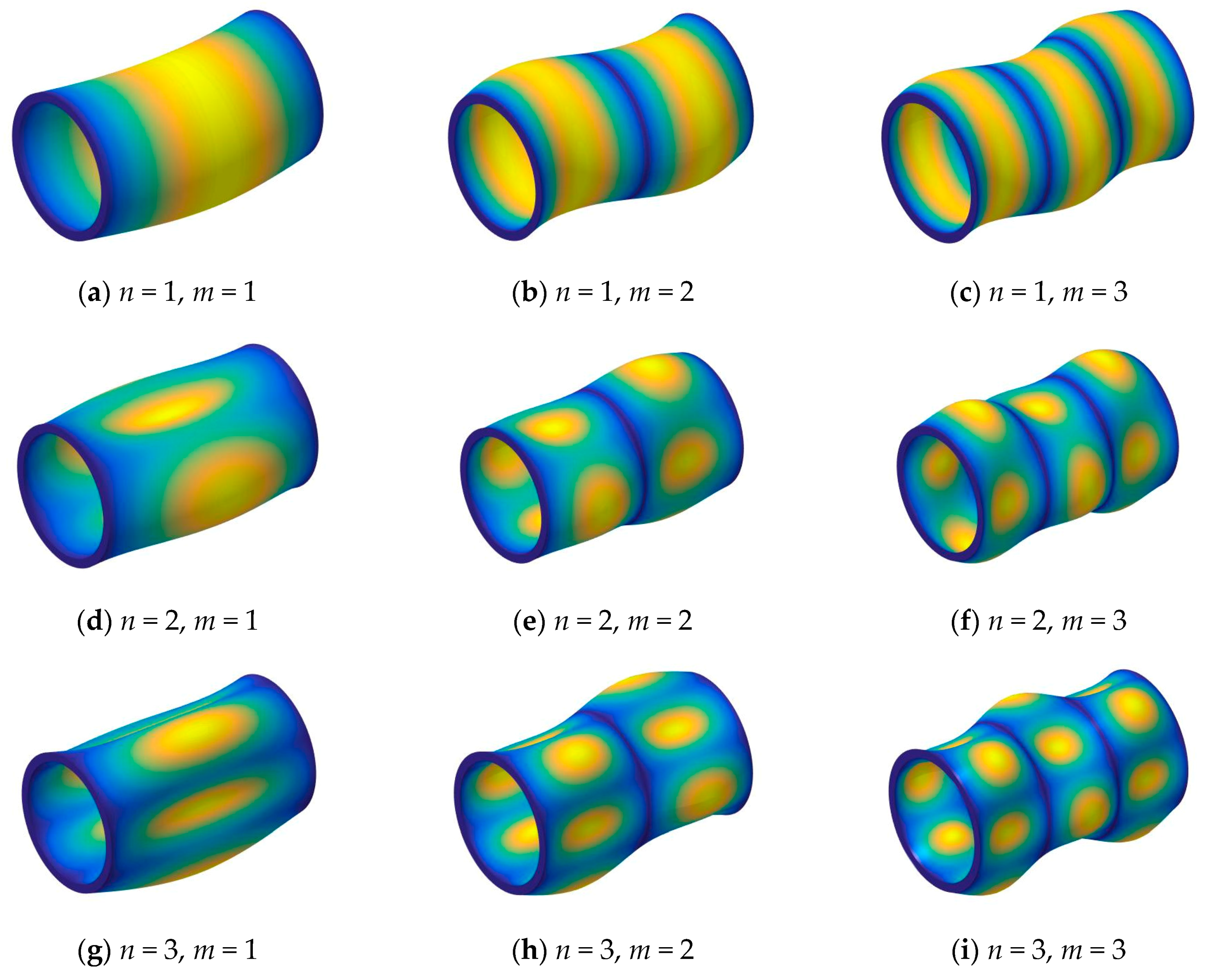
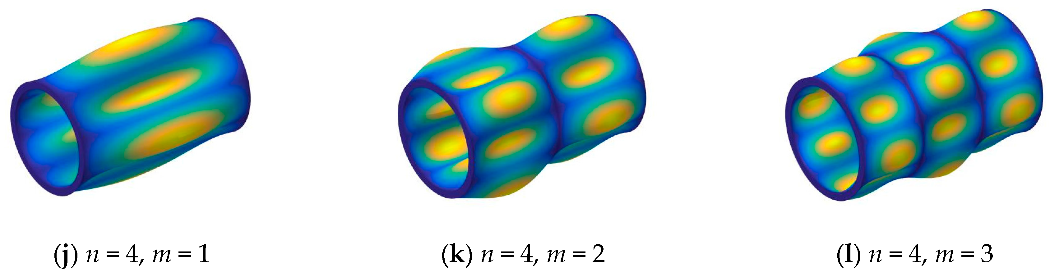
First, in Table 1, the three layered [0°/90°/0°] composite shell under some classical boundary conditions is considered (i.e., F-F, S-S, C-C). The material properties and geometric parameters are given as: R = 1 m, L/R = 5, h/R = 0.05, E2 = 1 GPa, E1/E2 = 25, μ12 = 0.25, G12 = 0.5E2, G13 = 0.5E2, G23 = 0.2E2, ρ = 1700 kg/m3. The comparison of the frequency parameter is studied. The first four circumferential wave numbers (i.e., n = 1, 2, 3, 4) and the first longitudinal mode (i.e., m = 1) are calculated. The frequency parameters are compared with the results by Messia and Soldatos [56] and Jin et al. [57], from Table 1, the differences between the results by the present method and reported literatures are small, the maximum error is 3.01%. The differences are caused by different solution program methods. Furthermore, in each circumferential wave number, the maximum frequency parameters are under the boundary condition C-C, especially, when n = 1, the maximum frequency parameter is fixed under the boundary condition F-F. The reason is that the boundary conditions have a significant effect on the frequency parameters. In order to further investigate the free vibration characteristics of composite laminated cylindrical shells with arbitrary boundary conditions, some mode shapes (n, m) of the composite laminated cylindrical shell are shown in Figure 2.
The numerical examples in the previous studies considered the thin composite shell with various classical boundary conditions. To verify the correctness of the present method, more numerical examples are considered. In Table 2, the fundamental frequency parameter of the moderately thick composite shell with the different length to radius ratios under four types of classical boundary conditions (i.e., S-S, S-C, C-C, C-F) are shown. There are two types of cross-ply laminated schemes (i.e., [0°/90°] and [0°/90°/0°]) and two kinds of length to radius ratios (i.e., L/R = 1, 2) are discussed. The results of the present method are compared with the results by Khdeir et al. [58], Thinh and Nguyen [59] and Jin et al. [57]. The geometric and material parameters are given as: R = 1 m, h/R = 0.2, E2 = 1 GPa, E1/E2 = 40, μ12 = 0.25, G12 = 0.6E2, G13 = 0.5E2, G13 = 0.5E2, ρ = 1600 kg/m3. From Table 2, the results of the present method agree well with the results in the literatures, the small differences are related to different shell theory and numerical methods. For solving the vibration characteristics of the moderately thick composite laminated cylindrical shell, the vibration characteristics of the whole system can be solved by the elastic equation: (K−ω2 × M) = 0, where K is the stiffness matrix for the shallow shell and M is the mass matrix, ω is the natural frequency for the moderately thick composite laminated cylindrical shell. Different boundary conditions cause the stiffness matrix to change. For the simply-supported (S-S) boundary condition, the determinant of the stiffness matrix becomes smaller compared to the clamped (C-C) boundary condition, and when the mass matrix remains unchanged, the natural frequency decreases. When the length to radius value changes from 1 to 2, the length quadratic variable in the frequency parameter will be four times larger, and the frequency parameters are also increased. So, the effect of the length to radius ratios on the free vibration characteristics cannot be expressed.
Next, the effect of thickness to radius ratios on the frequency parameter is considered, the boundary condition is set as simply-supported. Two types of cross-ply laminated schemes (i.e., [0°/90°/90°/0°] and [0°/90°/90°/0°]) and three kinds of thickness to radius ratios (i.e., h/R = 0.1, 0.2, 0.3) are discussed. The material parameters and geometric constants are same as the previous example, the ratio of length to radius is given as L/R = 1. The frequency parameters of the three lowest natural frequencies are compared with the results in the literature that were investigated by Thinh [59] and Jin et al. [57]. From Table 3, the differences between the results of the present method and other results in the literature are small, and the differences are related to a variety of numerical methods and shell theories.
For analysis of the effect of length to radius ratios and thickness to radius ratios, one type of three-layered cross-ply [0°/90°/0°] composite laminated cylindrical shell with simply-supported and clamped boundary conditions is considered. The first longitudinal modal (i.e., m = 1) frequency parameter is calculated for different circumferential numbers (i.e., n = 1, 2, 3) with various thickness to radius ratios (i.e., h/R = 0.05–0.1), and length to radius ratios (i.e., L/R = 1–4) are calculated in Table 4 and Table 5. The material properties are given as: E2 = 2 GPa, E1/E2 = 25, μ12 = 0.25, G12 = 0.5E2, G13 = 0.5E2, G23 = 0.2E2, ρ = 1600 kg/m3. When studying the effect of the length to radius ratios, keeping material parameters and radius constant, the frequency parameters are only related to the natural frequency of the moderately thick composite laminated cylindrical shell. It can be seen from Table 4 and Table 5, with the growth of the length to the radius ratios L/R, the frequency parameter is generally decreased. Furthermore, the frequency parameter generally grows with the thickness to radius ratio increase. So, the effects of length to radius ratio and thickness to radius ratio are different from the frequency parameter of the moderately thick composite laminated cylindrical shell with simply-supported and clamped boundary conditions.
3.2. Composite Laminated Cylindrical Shell with Elastic Boundary Conditions
It is necessary and significant to study the vibration analysis of the composite laminated cylindrical shell under elastic restrained. Through the introducing of the elastic boundary conditions, the stiffness transform matrix is established by different elastic boundary conditions, in this paper, four types of typical elastic boundary conditions are considered:
Type 1 (EC1): axial displacement is under elastic restrained and the corresponding stiffness transform matrix Kδ is given as:
Type 2 (EC2): circumferential displacement is under elastic restrained and the corresponding stiffness transform matrix Kδ is given as:
Type 3 (EC3): radial displacement is under elastic restrained and the corresponding stiffness transform matrix Kδ is given as:
Type 4 (EC4): axial and circumferential displacements are under elastic restrained and the corresponding stiffness transform matrix Kδ is given as:
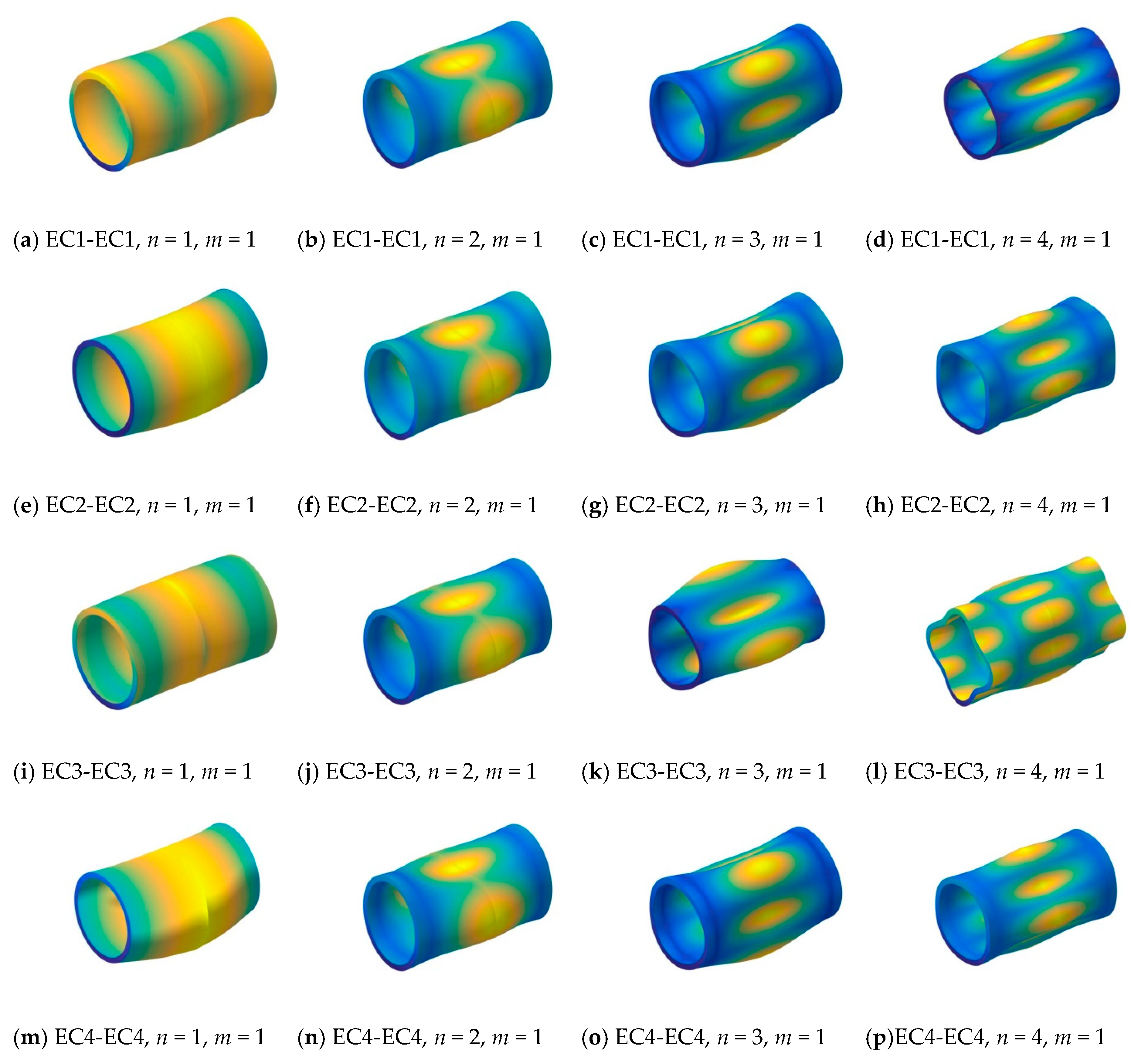
First, two types—[0°/90°/0°] and [0°/90°]—of composite laminated cylindrical shells with classical and elastic boundary conditions (i.e., SD-SD, S-S, C-C, EC1-EC1, EC2-EC2, EC3-EC3, EC4-EC4) are discussed. The first longitudinal mode frequency parameter is calculated for various circumferential numbers (i.e., n = 1, 2, 3, 4). The material properties and geometric parameters are given as: L/R = 4, h/R = 0.1, E2 = 2 GPa, E1/E2 = 25, μ12 = 0.25, G12 = 0.5E2, G13 = 0.5E2, G23 = 0.2E2, ρ = 1500 kg/m3. The results calculated by the present method are compared with the solutions by Jin et al. [57] in Table 6 and Table 7. From the table, it is obvious that with different elastic boundary conditions for different layer-type composite shells, the highest frequency parameters are listed in the columns with elastic boundary condition EC1-EC1 in circumferential mode n = 1, and in the other circumferential mode n = 2, 3, 4, they appear in the columns with elastic boundary condition EC2-EC2. It is because the frequency parameter is related to the boundary condition and circumferential mode. In order to further investigate the free vibration characteristics of composite laminated cylindrical shells with elastic boundary conditions, some mode shapes (n, m) of the composite laminated cylindrical shell are shown in Figure 3.
Next, the effect of the stiffness constants is investigated. A three-layered cross-ply [90°/0°/90°] composite shell with complicated elastic boundary conditions is considered. The composite shell is under elastic restrained with one kind of spring stiffness in each displacement direction at one end; on the other end, the composite shell is under the simply-supported boundary condition. The first longitudinal mode (i.e., m = 1) frequency parameter is calculated for various circumferential numbers (i.e., n = 1, 2, 3, 4) with different elastic restrained Ku, Kv, Kw, Kϕx, Kϕθ, which are calculated with various stiffness constants (i.e., 0–1012). The material parameters and geometric properties are given as: L/R = 4, h/R = 0.1, E2 = 2 GPa, E1/E2 = 25, μ12 = 0.25, G12 = 0.5E2, G13 = 0.5E2, G23 = 0.2E2, ρ = 1500 kg/m3. From Table 8, the frequency parameters are almost all in one certain value when the composite shell is only restrained by the rotation spring Kϕx and Kϕθ. When the composite shell is only restrained by the circumferential Kv and radial spring Kw, the frequency parameters generally increase with the changing of the stiffness constant. When the composite shell is only restrained by the axial spring Ku, the frequency parameters have smaller growth with the increasing of the stiffness constants. It can be founded that the effect of circumferential spring Kv and radial spring Kw are more obvious than the other direction springs. When the circumferential wave number n = 1, the increase of the frequency parameters is larger than n = 2, 3. So, when the composite shell is under the S-elastic boundary condition, the effects of circumferential Kv and radial spring Kw are more obvious than the other direction springs.
Furthermore, the composite shell is considered under the S-elastic boundary condition in which only one displacement is under elastic restrained and other displacements are fixed. The frequency parameter, material constants and geometric properties are the same as the previous example. In Table 8, the frequency parameter is calculated. The expression of boundary matrix B1(x) and B2(x) are reduced as:
For different elastic boundary conditions, the corresponding stiffness transform matrices Kδ are given as:
In Table 9, the frequency parameters with different elastic restrained stiffness constants are calculated. It is obvious that with the changing of the stiffness constants from 0 to 1012, the frequency parameters are almost unchanged and remain in a certain range. So the effect of the elastic restrained stiffness constants for the S-elastic boundary condition, which is set as one displacement restrained and others are fixed of the composite shell, are small and the frequency parameters are almost all remaining in a stable range. So, for various elastic boundary condition combinations, the effects of the elastic spring restrained on the free vibration characteristics of moderately thick composite laminated cylindrical shells are different. In some cases, the effect of the elastic restrained springs is obvious. Also, the effect of the elastic restrained spring is not obvious in some numerical cases.
4. Conclusions
The wave base method is conducted to analyze the free vibration characteristics of moderately thick composite laminated cylindrical shells with arbitrary classical and elastic boundary conditions. According to the first-order shear deformation shell theory and Hamilton principle, the governing equation of the composite laminated shell is established. The displacement variables are transformed into wave function forms. Related to different boundary conditions, the boundary matrices are obtained to establish the total matrix. The natural frequencies are solved by the dichotomy method to experiment with the zero location of the total matrix determinant. For the wave based method, the advantage is that the boundary conditions are easy to replace. If the boundary conditions need to be changed, only the boundary condition matrix B1 and B2 need to be changed, including classical boundaries, elastic boundaries and their combined forms. To analyze the free vibration characteristics of moderately thick composite laminated shells, the solutions are easy to obtain in the wave function forms, and the shell structure does not need to be divided into shell segments. For the free vibration characteristics of the moderately thick composite laminated cylindrical shell with arbitrary boundary conditions, the solutions by the present method have better precision than the results in some reported literatures. Furthermore, some numerical examples are shown and the conclusions follow as:
First, the frequency parameters of moderately thick composite laminated cylindrical shells with arbitrary boundary conditions are calculated. Through the comparison of the results, it can be seen that the method proposed in this paper is more accurate for the calculation of the shell.
Second, the effect of the geometric constants, such as length to radius ratios and thickness to thickness ratios, on the frequency parameters are discussed. It is seen that different geometric constants have various effects on the frequency parameters.
Third, the influence of the boundary elastic restrained stiffness constants on the natural frequency parameters is discussed. The changing ranges of the elastic restrained stiffness constants in various directions are from 0–1012. From the variations of the natural frequency parameters, it can be concluded that the effect of the elastic restrained stiffness on the natural frequency parameters is not obvious. With the growth of the stiffness constants in various directions, the natural frequencies have a small range of fluctuations and are basically stable within a range.
Author Contributions
Methodology, D.S.; validation, D.H. and Q.W.; formal analysis, D.H.; investigation, D.H. and Q.W.; data curation, D.H. and Q.W.; writing—original draft preparation, D.H. and C.M.; writing—review and editing, Q.W. visualization, D.H.; supervision, D.S. and H.S. All authors have read and agreed to the published version of the manuscript.
Funding
This research was funded by the National Natural Science Foundation of China (Grant Nos.51679056, 51705537 and 51875112), Innovation Driven Program of Central South University (Grant number:2019CX006), and the Natural Science Foundation of Hunan Province of China (2018JJ3661). The authors also gratefully acknowledge the supports from State Key Laboratory of High Performance Complex Manufacturing, Central South University, China (Grant No. ZZYJKT2018-11).
Conflicts of Interest
The authors declare no conflict of interest.
References
- Leissa, A.W. Vibration of Shells; Scientific and Technical Information Office, National Aeronautics and Space Administration Washington: Washington, DC, USA, 1973; Volume 288.
- Qatu, M.S. Vibration of Laminated Shells and Plates; Elsevier: Amsterdam, The Netherlands, 2004. [Google Scholar]
- Qatu, M.S. Recent research advances in the dynamic behavior of shells: 1989–2000, Part 1: Laminated composite shells. Appl. Mech. Rev. 2002, 55, 325–350. [Google Scholar] [CrossRef]
- Qatu, M.S. Recent research advances in the dynamic behavior of shells: 1989–2000, Part 2: Homogeneous shells. Appl. Mech. Rev. 2002, 55, 415–434. [Google Scholar] [CrossRef]
- Qatu, M.S.; Sullivan, R.W.; Wang, W. Recent research advances on the dynamic analysis of composite shells: 2000–2009. Compos. Struct. 2011, 93, 14–31. [Google Scholar] [CrossRef]
- Reddy, J.N. Mechanics of Laminated Composite Plates and Shells: Theory and Analysis; CRC Press: Boca Raton, FL, USA, 2004. [Google Scholar]
- Carrera, E.; Brischetto, S.; Nali, P. Numerical Evaluation of Classical Theories and Their Limitations; John Wiley & Sons, Ltd: Chichester, UK, 2011. [Google Scholar]
- Carrera, E. Theories and finite elements for multilayered, anisotropic, composite plates and shells. Arch. Comput. Methods Eng. 2002, 9, 87–140. [Google Scholar] [CrossRef]
- Ye, J. Laminated Composite Plates and Shells; Springer Science & Business Media: Boston, NY, USA, 2003. [Google Scholar]
- Noor, A.K.; Burton, W.S.; Peters, J.M. Assessment of computational models for multilayered composite cylinders. Int. J. Solids Struct. 1991, 27, 1269–1286. [Google Scholar] [CrossRef]
- Toorani, M.H.; Lakis, A.A. General equations of anisotropic plates and shells including transverse shear deformations, rotary inertia and initial curvature effects. J. Sound Vib. 2000, 237, 561–615. [Google Scholar] [CrossRef]
- Liew, K.M.; Zhao, X.; Ferreira, A.J.M. A review of meshless methods for laminated and functionally graded plates and shells. Compos. Struct. 2011, 93, 2031–2041. [Google Scholar] [CrossRef]
- Akhlaque-E-Rasul, S.; Ganesan, R. The Compressive Response of Thickness-Tapered Shallow Curved Composite Plates Based on Classical Shell Theory. J. Adv. Mater. Cov. 2011, 43, 47–65. [Google Scholar]
- Berdichevsky, V.; Misyura, V. Effect of Accuracy Loss in Classical Shell Theory. J. Appl. Mech. 1992, 59, S217–S223. [Google Scholar] [CrossRef]
- Kienzler, R. An extension of the classical shell theory; the influence of thickness strains and of warping of the cross-sections. Ing. Arch. 1982, 52, 311–322. [Google Scholar] [CrossRef]
- Wisniewski, K. A shell theory with independent rotations for relaxed Biot stress and right stretch strain. Comput. Mech. 1998, 21, 101–122. [Google Scholar] [CrossRef]
- Hosseini-Hashemi, S.; Ilkhani, M.R. Exact solution for free vibrations of spinning nanotube based on nonlocal first order shear deformation shell theory. Compos. Struct. 2016, 157, 1–11. [Google Scholar] [CrossRef]
- Kreja, I.; Schmidt, R.; Reddy, J.N. Finite elements based on a first-order shear deformation moderate rotation shell theory with applications to the analysis of composite structures. Int. J. Non-Linear Mech. 1997, 32, 1123–1142. [Google Scholar] [CrossRef]
- Viswanathan, K.; Javed, S. Free vibration of anti-symmetric angle-ply cylindrical shell walls using first-order shear deformation theory. J. Vib. Control 2016, 22. [Google Scholar] [CrossRef]
- Kim, J.S. Reconstruction of First-Order Shear Deformation Shell Theory for Laminated and Sandwich Shells. AIAA J. 1971, 42, 1685–1697. [Google Scholar] [CrossRef]
- Shao, D.; Wang, Q.; Qin, B. A simple first-order shear deformation shell theory for vibration analysis of composite laminated open cylindrical shells with general boundary conditions. Compos. Struct. 2018, 184, 211–232. [Google Scholar]
- Neves, A.M.A.; Ferreira, A.J.; Carrera, E.; Cinefra, M.; Roque, C.M.; Jorge, R.M.; Soares, C.M. Free vibration analysis of functionally graded shells by a higher-order shear deformation theory and radial basis functions collocation, accounting for through-the-thickness deformations. Eur. J. Mech. A Solids 2013, 37, 24–34. [Google Scholar] [CrossRef] [Green Version]
- Viola, E.; Tornabene, F.; Fantuzzi, N. General higher-order shear deformation theories for the free vibration analysis of completely doubly-curved laminated shells and panels. Compos. Struct. 2013, 95, 639–666. [Google Scholar] [CrossRef]
- Reddy, J.N.; Liu, C.F. A higher-order shear deformation theory of laminated elastic shells. Int. J. Eng. Sci. 1985, 23, 319–330. [Google Scholar] [CrossRef]
- Tsai, C.T.; Palazotto, A.N. A modified riks approach to composite shell snapping using a high-order shear deformation theory. Comput. Struct. 1990, 35, 221–226. [Google Scholar] [CrossRef]
- Viola, E.; Tornabene, F.; Fantuzzi, N. Static analysis of completely doubly-curved laminated shells and panels using general higher-order shear deformation theories. Compos. Struct. 2013, 101, 59–93. [Google Scholar] [CrossRef]
- Alijani, F.; Aghdam, M.M. A semi-analytical solution for stress analysis of moderately thick laminated cylindrical panels with various boundary conditions. Compos. Struct. 2009, 89, 543–550. [Google Scholar] [CrossRef]
- Hosseini-Hashemi, S.; Ilkhani, M.R.; Fadaee, M. Accurate natural frequencies and critical speeds of a rotating functionally graded moderately thick cylindrical shell. Int. J. Mech. Sci. 2013, 76, 9–20. [Google Scholar] [CrossRef]
- Sakka, Z.I.; Abdalla, J.A.; Kabir, H.R.H. Free vibration response of shear-flexible moderately-thick orthotropic cylindrical shells. Int. J. Struct. Stab. Dyn. 2006, 6, 121–138. [Google Scholar] [CrossRef]
- Hao, P.; Liu, X.; Wang, Y.; Liu, D.; Wang, B.; Li, G. Collaborative design of fiber path and shape for complex composite shells based on isogeometric analysis. Comput. Methods Appl. Mech. Eng. 2019, 354, 181–212. [Google Scholar] [CrossRef]
- Wang, Y.; Liao, Z.; Ye, M.; Zhang, Y.; Li, W.; Xia, Z. An efficient isogeometric topology optimization using multilevel mesh, MGCG and local-update strategy. Adv. Eng. Softw. 2020, 139, 102733. [Google Scholar] [CrossRef]
- Zhu, S.; Jin, G.; Ye, T. Free vibration analysis of moderately thick functionally graded open shells with general boundary conditions. Compos. Struct. 2014, 117, 169–186. [Google Scholar]
- Kurtaran, H. Geometrically nonlinear transient analysis of moderately thick laminated composite shallow shells with generalized differential quadrature method. Compos. Struct. 2015, 125, 605–614. [Google Scholar] [CrossRef]
- Maleki, S.; Tahani, M.; Andakhshideh, A. Static and transient analysis of laminated cylindrical shell panels with various boundary conditions and general lay-ups. ZAMM—J. Appl. Math. Mech. Z. Angew. Math. Mech. 2012, 92, 124–140. [Google Scholar] [CrossRef]
- Fazilati, J.; Ovesy, H.R. Boundary Condition Effects on the Parametric Stability of Moderately Thick Laminated Cylindrical Panels. Key Eng. Mater. 2011, 471–472, 466–471. [Google Scholar] [CrossRef]
- Tabiei, A.; Simitses, G. Torsional Instability of Moderately Thick Composite Cylindrical Shells by Various Shell Theories. Sci. Rep. 2015, 35, 1243–1246. [Google Scholar]
- Garcia, C.; Trendafilova, I.; Zucchelli, A. The Effect of Polycaprolactone Nanofibers on the Dynamic and Impact Behavior of Glass Fibre Reinforced Polymer Composites. J. Compos. Sci. 2018, 2, 43. [Google Scholar] [CrossRef] [Green Version]
- Garcia, C.; Wilson, J.; Trendafilova, I.; Yang, L. Vibratory behaviour of glass fibre reinforced polymer (GFRP) interleaved with nylon nanofibers. Compos. Struct. 2017, 176, 923–932. [Google Scholar] [CrossRef] [Green Version]
- Yang, N.; Chen, L.Y.; Zhang, Y.F. Wave based method for steady-state power flow analysis. J. Vib. Shock 2014, 33, 173–177. [Google Scholar]
- Koo, K.; Pluymers, B.; Desmet, W.; Wang, S. Vibro-acoustic design sensitivity analysis using the wave-based method. J. Sound Vib. 2011, 330, 4340–4351. [Google Scholar] [CrossRef]
- He, X.S.; Huang, Q.B.; Peng, W.C. Wave based method for mid-frequency analysis of coupled vibro-acoustic problem. Int. J. Mech. Mater. Des. 2008, 4, 21–29. [Google Scholar] [CrossRef]
- Chen, M.; Xie, K.; Xu, K.; Yu, P. Wave Based Method for Free and Forced Vibration Analysis of Cylindrical Shells with Discontinuity in Thickness. J. Vib. Acoust. 2015, 137, 051004. [Google Scholar] [CrossRef]
- Chen, W.; Wei, J.; Xie, K.; Deng, N.; Hou, G. Wave based method for free vibration analysis of ring stiffened cylindrical shell with intermediate large frame ribs. Shock Vib. 2013, 20, 459–479. [Google Scholar] [CrossRef]
- He, D.; Shi, D.; Wang, Q.; Shuai, C. Wave based method (WBM) for free vibration analysis of cross-ply composite laminated cylindrical shells with arbitrary boundaries. Compos. Struct. 2019, 213, 284–298. [Google Scholar] [CrossRef]
- Shi, D.; He, D.; Wang, Q.; Ma, C.; Shu, H. Wave Based Method for Free Vibration Analysis of Cross-Ply Composite Laminated Shallow Shells with General Boundary Conditions. Materials 2019, 12, 3808. [Google Scholar] [CrossRef] [Green Version]
- Wei, J.; Chen, M.; Hou, G.; Xie, K.; Deng, N. Wave Based Method for Free Vibration Analysis of Cylindrical Shells with Nonuniform Stiffener Distribution. J. Vib. Acoust. 2013, 135, 061011. [Google Scholar] [CrossRef]
- Xie, K.; Chen, M.; Deng, N.; Xu, K. Wave Based Method for Vibration and Acoustic Characteristics Analysis of Underwater Cylindrical Shell with Bulkheads; INTER-NOISE and NOISE-CON Congress and Conference Proceedings, 2014; Institute of Noise Control Engineering: Washington, DC, USA, 2014; pp. 572–581. [Google Scholar]
- Xie, K.; Chen, M.; Zhang, L.; Xie, D. Wave based method for vibration analysis of elastically coupled annular plate and cylindrical shell structures. Appl. Acoust. 2017, 123, 107–122. [Google Scholar] [CrossRef]
- Reddy, J.N. Exact solutions of moderately thick laminated shells. J. Eng. Mech. 1984, 110, 794–809. [Google Scholar] [CrossRef]
- Gao, C.; Pang, F.; Li, H.; Li, L. An approximate solution for vibrations of uniform and stepped functionally graded spherical cap based on Ritz method. Compos. Struct. 2020, 233, 111640. [Google Scholar] [CrossRef]
- Liu, T.; Wang, A.; Wang, Q.; Qin, B. Wave based method for free vibration characteristics of functionally graded cylindrical shells with arbitrary boundary conditions. Thin-Walled Struct. 2020, 148, 106580. [Google Scholar] [CrossRef]
- Qin, B.; Zhong, R.; Wang, T.; Wang, Q.; Xu, Y.; Hu, Z. A unified Fourier series solution for vibration analysis of FG-CNTRC cylindrical, conical shells and annular plates with arbitrary boundary conditions. Compos. Struct. 2020, 232, 111549. [Google Scholar] [CrossRef]
- Qin, Z.; Zhao, S.; Pang, X.; Safaei, B.; Chu, F. A unified solution for vibration analysis of laminated functionally graded shallow shells reinforced by graphene with general boundary conditions. Int. J. Mech. Sci. 2020, 170, 105341. [Google Scholar] [CrossRef]
- Zhang, H.; Zhu, R.; Shi, D.; Wang, Q.; Yu, H. Study on vibro-acoustic property of composite laminated rotary plate-cavity system based on a simplified plate theory and experimental method. Int. J. Mech. Sci. 2020, 167, 105264. [Google Scholar] [CrossRef]
- Wang, Q.; Zhong, R.; Qin, B.; Yu, H. Dynamic analysis of stepped functionally graded piezoelectric plate with general boundary conditions. Smart Mater. Struct. 2020, 29, 035022. [Google Scholar] [CrossRef]
- Messina, A.; Soldatos, K.P. Ritz-Type Dynamic Analysis of Cross-Ply Laminated Circular Cylinders Subjected to Different Boundary Conditions. J. Sound Vib. 1999, 227, 749–768. [Google Scholar] [CrossRef]
- Jin, G.; Ye, T.; Ma, X.; Chen, Y.; Su, Z.; Xie, X. A unified approach for the vibration analysis of moderately thick composite laminated cylindrical shells with arbitrary boundary conditions. Int. J. Mech. Sci. 2013, 75, 357–376. [Google Scholar] [CrossRef]
- Khdeir, A.A.; Reddy, J.N.; Frederick, D. A study of bending, vibration and buckling of cross-ply circular cylindrical shells with various shell theories. Int. J. Eng. Sci. 1989, 27, 1337–1351. [Google Scholar] [CrossRef]
- Thinh, T.I.; Nguyen, M.C. Dynamic stiffness matrix of continuous element for vibration of thick cross-ply laminated composite cylindrical shells. Compos. Struct. 2013, 98, 93–102. [Google Scholar] [CrossRef]
Figure 1.
The schematic diagram of the moderately thick composite laminated cylindrical shell with elastic boundary conditions: (a) the whole composite shell; (b) the cross-section view of the composite shell.
Figure 1.
The schematic diagram of the moderately thick composite laminated cylindrical shell with elastic boundary conditions: (a) the whole composite shell; (b) the cross-section view of the composite shell.

Figure 2.
The modal shapes of a three-layered [0°/90°/0°] composite shell with simply-supported (S-S) boundary conditions.
Figure 2.
The modal shapes of a three-layered [0°/90°/0°] composite shell with simply-supported (S-S) boundary conditions.


Figure 3.
The modal shapes of a three-layered [0°/90°/0°] composite shell with various elastic boundary conditions.
Figure 3.
The modal shapes of a three-layered [0°/90°/0°] composite shell with various elastic boundary conditions.


Table 1.
Frequency parameters for a three-layer cross-ply cylindrical shell [0°/90°/0°] with various classical boundary conditions (R = 1 m, L/R = 5, h/R = 0.05, E2 = 1 GPa, E1/E2 = 25, μ12 = 0.25, G12 = 0.5E2, G13 = 0.5E2, G23 = 0.2E2, ρ = 1700 kg/m3; m = 1).
Table 1.
Frequency parameters for a three-layer cross-ply cylindrical shell [0°/90°/0°] with various classical boundary conditions (R = 1 m, L/R = 5, h/R = 0.05, E2 = 1 GPa, E1/E2 = 25, μ12 = 0.25, G12 = 0.5E2, G13 = 0.5E2, G23 = 0.2E2, ρ = 1700 kg/m3; m = 1).
| n | WBM | Ref. [56] | Error | Ref. [57] | Error |
|---|---|---|---|---|---|
| F-F | |||||
| 1 | 304.179 | 304.13 | 0.02% | 304.16 | 0.01% |
| 2 | 26.558 | 26.58 | −0.08% | 26.56 | −0.01% |
| 3 | 77.027 | 74.91 | 2.83% | 74.78 | 3.01% |
| 4 | 144.798 | 142.93 | 1.31% | 142.51 | 1.61% |
| 5 | 230.986 | 229.74 | 0.54% | 228.7 | 1.00% |
| SD-SD | |||||
| 1 | 151.486 | 151.49 | 0.00% | 151.49 | 0.00% |
| 2 | 92.564 | 92.57 | −0.01% | 92.57 | −0.01% |
| 3 | 95.253 | 95.37 | −0.12% | 95.27 | −0.02% |
| 4 | 149.999 | 150.42 | −0.28% | 150.01 | −0.01% |
| 5 | 232.927 | 233.97 | −0.45% | 232.94 | −0.01% |
| C-C | |||||
| 1 | 159.443 | 159.31 | 0.08% | 159.44 | 0.00% |
| 2 | 107.889 | 107.71 | 0.17% | 107.89 | 0.00% |
| 3 | 108.106 | 108.05 | 0.05% | 108.11 | 0.00% |
| 4 | 156.945 | 157.23 | −0.18% | 156.94 | 0.00% |
| 5 | 236.764 | 237.7 | −0.39% | 236.76 | 0.00% |
Table 2.
Frequency parameters for two types of cross-ply composite laminated cylindrical shell with different length to radius ratios and boundary conditions (R = 1 m, h/R = 0.2, E2 = 1 GPa, E1/E2 = 40, μ12 = 0.25, G12 = 0.6E2, G13 = 0.5E2, G13 = 0.5E2, ρ = 1600 kg/m3).
Table 2.
Frequency parameters for two types of cross-ply composite laminated cylindrical shell with different length to radius ratios and boundary conditions (R = 1 m, h/R = 0.2, E2 = 1 GPa, E1/E2 = 40, μ12 = 0.25, G12 = 0.6E2, G13 = 0.5E2, G13 = 0.5E2, ρ = 1600 kg/m3).
| Layer-Type | Shell Theories | S-S | S-C | C-C | C-F | ||||
|---|---|---|---|---|---|---|---|---|---|
| L/R = 1 | L/R = 2 | L/R = 1 | L/R = 2 | L/R = 1 | L/R = 2 | L/R = 1 | L/R = 2 | ||
| [0°/90°] | HSDT [58] | 0.0804 | 0.1556 | 0.0938 | 0.1726 | 0.1085 | 0.1928 | 0.0444 | 0.0921 |
| FSDT [58] | 0.0791 | 0.1552 | 0.0893 | 0.1697 | 0.1002 | 0.1876 | 0.0435 | 0.0914 | |
| CST [58] | 0.0866 | 0.1630 | 0.1152 | 0.1841 | 0.1048 | 0.2120 | 0.0480 | 0.0938 | |
| FSDT [59] | 0.0766 | 0.1519 | 0.0823 | 0.1661 | 0.0982 | 0.1737 | 0.0396 | 0.0872 | |
| FSDT [57] | 0.0881 | 0.1578 | 0.0921 | 0.1639 | 0.0982 | 0.1738 | 0.0396 | 0.0872 | |
| WBM | 0.0884 | 0.1581 | 0.0908 | 0.1631 | 0.0962 | 0.1723 | 0.0397 | 0.0873 | |
| [0°/90°/0°] | HSDT [58] | 0.1007 | 0.1777 | 0.1087 | 0.1972 | 0.1192 | 0.2191 | 0.0506 | 0.0995 |
| FSDT [58] | 0.1004 | 0.1779 | 0.1036 | 0.1945 | 0.1093 | 0.2129 | 0.0495 | 0.0988 | |
| CST [58] | 0.1479 | 0.2073 | 0.1850 | 0.2662 | 0.2049 | 0.3338 | 0.0669 | 0.1099 | |
| FSDT [59] | 0.0996 | 0.1722 | 0.1025 | 0.1950 | 0.1083 | 0.2083 | 0.0483 | 0.0914 | |
| FSDT [57] | 0.0996 | 0.1726 | 0.1028 | 0.1991 | 0.1086 | 0.2084 | 0.0483 | 0.0912 | |
| WBM | 0.0967 | 0.1706 | 0.0993 | 0.2043 | 0.1042 | 0.2017 | 0.0472 | 0.0907 | |
Table 3.
Frequency parameters for two types of cross-ply composite laminated cylindrical shells with different thickness to radius ratios under simply-supported boundary conditions (R = 1 m, L/R = 0.1, E2 = 1 GPa, E1/E2 = 40, μ12 = 0.25, G12 = 0.6E2, G13 = 0.5E2, G13 = 0.5E2, ρ = 1600 kg/m3).
Table 3.
Frequency parameters for two types of cross-ply composite laminated cylindrical shells with different thickness to radius ratios under simply-supported boundary conditions (R = 1 m, L/R = 0.1, E2 = 1 GPa, E1/E2 = 40, μ12 = 0.25, G12 = 0.6E2, G13 = 0.5E2, G13 = 0.5E2, ρ = 1600 kg/m3).
| h/R | [0°/90°/90°/0°] | [90°/0°/0°/90°] | ||||||||
|---|---|---|---|---|---|---|---|---|---|---|
| WBM | Ref. [57] | Error | Ref. [59] | Error | WBM | Ref. [57] | Error | Ref. [59] | Error | |
| 0.1 | 0.0638 | 0.0639 | −0.17% | 0.0640 | −0.32% | 0.0531 | 0.0533 | −0.38% | 0.0531 | 0.00% |
| 0.0656 | 0.0657 | −0.17% | 0.0657 | −0.17% | 0.0591 | 0.0592 | −0.24% | 0.0591 | −0.07% | |
| 0.0789 | 0.0789 | −0.05% | 0.0789 | −0.05% | 0.0709 | 0.0710 | −0.14% | 0.0709 | 0.00% | |
| 0.2 | 0.1586 | 0.1588 | −0.14% | 0.1589 | −0.20% | 0.1332 | 0.1335 | −0.22% | 0.1333 | −0.07% |
| 0.1676 | 0.1678 | −0.15% | 0.1683 | −0.44% | 0.1527 | 0.1528 | −0.06% | 0.1527 | 0.01% | |
| 0.1726 | 0.1727 | −0.07% | 0.1726 | −0.01% | 0.1590 | 0.1593 | −0.18% | 0.1592 | −0.12% | |
| 0.3 | 0.2539 | 0.2542 | −0.11% | 0.2546 | −0.27% | 0.2272 | 0.2275 | −0.12% | 0.2273 | −0.03% |
| 0.2669 | 0.2670 | −0.03% | 0.2669 | 0.01% | 0.2429 | 0.2430 | −0.03% | 0.2428 | 0.05% | |
| 0.2785 | 0.2788 | −0.11% | 0.2797 | 0.43% | 0.2697 | 0.2701 | −0.14% | 0.2699 | −0.07% | |
Table 4.
Frequency parameters for a three-layered cross-ply [0°/90°/0°] composite laminated cylindrical shell under simply-supported boundary conditions (E2 = 2 GPa, E1/E2 = 25, μ12 = 0.25, G12 = 0.5E2, G13 = 0.5E2, G23 = 0.2E2, ρ = 1600 kg/m3, m = 1).
Table 4.
Frequency parameters for a three-layered cross-ply [0°/90°/0°] composite laminated cylindrical shell under simply-supported boundary conditions (E2 = 2 GPa, E1/E2 = 25, μ12 = 0.25, G12 = 0.5E2, G13 = 0.5E2, G23 = 0.2E2, ρ = 1600 kg/m3, m = 1).
| h/R | L/R = 1 | L/R = 2 | L/R = 3 | L/R = 4 | ||||
|---|---|---|---|---|---|---|---|---|
| n = 1 | n = 2 | n = 1 | n = 2 | n = 1 | n = 2 | n = 1 | n = 2 | |
| 0.05 | 1.54962 | 1.12747 | 0.78125 | 0.51865 | 0.52133 | 0.33977 | 0.39057 | 0.25367 |
| 0.06 | 1.58005 | 1.18476 | 0.78545 | 0.53046 | 0.52261 | 0.34539 | 0.39112 | 0.25800 |
| 0.07 | 1.61120 | 1.24206 | 0.79021 | 0.54365 | 0.52408 | 0.35183 | 0.39177 | 0.26299 |
| 0.08 | 1.64201 | 1.29756 | 0.79546 | 0.55794 | 0.52575 | 0.35899 | 0.39250 | 0.26857 |
| 0.09 | 1.67168 | 1.35011 | 0.80111 | 0.57306 | 0.52760 | 0.36680 | 0.39331 | 0.27468 |
| 0.1 | 1.69971 | 1.39908 | 0.80707 | 0.58877 | 0.52961 | 0.37516 | 0.39421 | 0.28127 |
Table 5.
Frequency parameters for a three-layered cross-ply [0°/90°/0°] composite laminated cylindrical shell with clamped boundary conditions (E2 = 2 GPa, E1/E2 = 25, μ12 = 0.25, G12 = 0.5E2, G13 = 0.5E2, G23 = 0.2E2, ρ = 1600 kg/m3, m = 1).
Table 5.
Frequency parameters for a three-layered cross-ply [0°/90°/0°] composite laminated cylindrical shell with clamped boundary conditions (E2 = 2 GPa, E1/E2 = 25, μ12 = 0.25, G12 = 0.5E2, G13 = 0.5E2, G23 = 0.2E2, ρ = 1600 kg/m3, m = 1).
| h/R | L/R = 1 | L/R = 2 | L/R = 3 | L/R = 4 | ||||
|---|---|---|---|---|---|---|---|---|
| n = 1 | n = 2 | n = 1 | n = 2 | n = 1 | n = 2 | n = 1 | n = 2 | |
| 0.05 | 1.74397 | 1.45928 | 0.82781 | 0.60980 | 0.54152 | 0.37875 | 0.40177 | 0.27465 |
| 0.06 | 1.79223 | 1.53994 | 0.84181 | 0.63996 | 0.54739 | 0.39300 | 0.40492 | 0.28362 |
| 0.07 | 1.83113 | 1.60423 | 0.85551 | 0.66928 | 0.55335 | 0.40776 | 0.40814 | 0.29316 |
| 0.08 | 1.86213 | 1.65516 | 0.86864 | 0.69708 | 0.55934 | 0.42277 | 0.41142 | 0.30314 |
| 0.09 | 1.88682 | 1.69562 | 0.88099 | 0.72294 | 0.56529 | 0.43778 | 0.41473 | 0.31345 |
| 0.1 | 1.90656 | 1.72802 | 0.89243 | 0.74672 | 0.57113 | 0.45260 | 0.41806 | 0.32398 |
Table 6.
Frequency parameters for two types of cross-ply composite laminated cylindrical shells with classical boundary conditions (L/R = 4, h/R = 0.1, E2 = 2 GPa, E1/E2 = 25, μ12 = 0.25, G12 = 0.5E2, G13 = 0.5E2, G23 = 0.2E2, ρ = 1500 kg/m3, m = 1).
Table 6.
Frequency parameters for two types of cross-ply composite laminated cylindrical shells with classical boundary conditions (L/R = 4, h/R = 0.1, E2 = 2 GPa, E1/E2 = 25, μ12 = 0.25, G12 = 0.5E2, G13 = 0.5E2, G23 = 0.2E2, ρ = 1500 kg/m3, m = 1).
| Layer- | n | SD-SD | S-S | C-C | |||
|---|---|---|---|---|---|---|---|
| Type | Ref. [57] | WBM | Ref. [57] | WBM | Ref. [57] | WBM | |
| [0°/90°/0°] | 1 | 61.94 | 61.939 | 63.069 | 63.074 | 66.887 | 66.889 |
| 2 | 42.76 | 42.739 | 44.99 | 45.003 | 51.846 | 51.837 | |
| 3 | 55.85 | 55.803 | 57.428 | 57.443 | 63.007 | 62.979 | |
| 4 | 92.309 | 92.249 | 93.101 | 93.108 | 96.611 | 96.569 | |
| [0°/90°] | 1 | 59.523 | 59.523 | 62.065 | 62.069 | 62.677 | 62.676 |
| 2 | 43.199 | 43.205 | 47.847 | 47.854 | 48.488 | 48.488 | |
| 3 | 73.147 | 73.145 | 75.891 | 75.888 | 76.138 | 76.13 | |
| 4 | 128.58 | 128.56 | 130.02 | 130.009 | 130.13 | 130.112 | |
Table 7.
Frequency parameters for two types of cross-ply composite laminated cylindrical shells with elastic boundary conditions (L/R = 4, h/R = 0.1, E2 = 2 GPa, E1/E2 = 25, μ12 = 0.25, G12 = 0.5E2, G13 = 0.5E2, G23 = 0.2E2, ρ = 1500 kg/m3, m = 1).
Table 7.
Frequency parameters for two types of cross-ply composite laminated cylindrical shells with elastic boundary conditions (L/R = 4, h/R = 0.1, E2 = 2 GPa, E1/E2 = 25, μ12 = 0.25, G12 = 0.5E2, G13 = 0.5E2, G23 = 0.2E2, ρ = 1500 kg/m3, m = 1).
| Layer- | n | EC1-EC1 | EC2-EC2 | EC3-EC3 | EC4-EC4 | ||||
|---|---|---|---|---|---|---|---|---|---|
| Type | Ref. [57] | WBM | Ref. [57] | WBM | Ref. [57] | WBM | Ref. [57] | WBM | |
| [0°/90°/0°] | 1 | 65.844 | 65.788 | 65.767 | 62.014 | 60.544 | 65.508 | 59.906 | 58.511 |
| 2 | 50.056 | 50.019 | 51.223 | 51.279 | 50.187 | 49.273 | 49.672 | 49.629 | |
| 3 | 61.725 | 61.682 | 62.916 | 62.893 | 61.619 | 59.397 | 61.709 | 61.667 | |
| 4 | 95.949 | 95.902 | 96.592 | 96.551 | 95.548 | 102.61 | 95.949 | 95.902 | |
| [0°/90°] | 1 | 61.265 | 61.167 | 56.838 | 55.912 | 62.231 | 62.15 | 55.912 | 54.997 |
| 2 | 46.054 | 46.02 | 47.977 | 47.981 | 48.019 | 47.859 | 45.792 | 45.772 | |
| 3 | 74.745 | 74.738 | 76.084 | 76.083 | 75.941 | 75.817 | 74.743 | 74.737 | |
| 4 | 129.44 | 129.428 | 130.12 | 130.104 | 130.03 | 129.929 | 129.44 | 129.425 | |
Table 8.
The frequency parameters for a three-layered cross-ply [0°/90°/0°] composite laminated cylindrical shell with S-elastic boundary conditions, one displacement is under elastic restrained and others are free (L/R = 4, h/R = 0.1, E2 = 2 GPa, E1/E2 = 25, μ12 = 0.25, G12 = 0.5E2, G13 = 0.5E2, G23 = 0.2E2, ρ = 1500 kg/m3).
| Spring Stiffness | Ku | Kv | Kw | Kϕx | Kϕθ | ||||||||||
|---|---|---|---|---|---|---|---|---|---|---|---|---|---|---|---|
| n = 1 | n = 2 | n = 3 | n = 1 | n = 2 | n = 3 | n = 1 | n = 2 | n = 3 | n = 1 | n = 2 | n = 3 | n = 1 | n = 2 | n = 3 | |
| 0 | 29.069 | 56.813 | 142.978 | 29.069 | 56.813 | 142.978 | 29.069 | 56.813 | 142.978 | 29.069 | 56.813 | 142.978 | 29.069 | 56.813 | 142.978 |
| 101 | 29.069 | 56.813 | 142.978 | 29.069 | 56.813 | 142.978 | 29.069 | 56.813 | 142.978 | 29.069 | 56.813 | 142.978 | 29.069 | 56.813 | 142.978 |
| 102 | 29.069 | 56.813 | 142.978 | 29.069 | 56.813 | 142.978 | 29.069 | 56.813 | 142.978 | 29.069 | 56.813 | 142.978 | 29.069 | 56.813 | 142.978 |
| 103 | 29.069 | 56.813 | 142.978 | 29.069 | 56.813 | 142.978 | 29.069 | 56.813 | 142.978 | 29.069 | 56.813 | 142.978 | 29.069 | 56.813 | 142.978 |
| 104 | 29.069 | 56.813 | 142.978 | 29.075 | 56.814 | 142.978 | 29.075 | 56.819 | 142.981 | 29.069 | 56.813 | 142.976 | 29.069 | 56.815 | 142.982 |
| 105 | 29.069 | 56.813 | 142.978 | 29.131 | 56.829 | 142.981 | 29.131 | 56.876 | 143.005 | 29.069 | 56.811 | 142.958 | 29.069 | 56.837 | 143.024 |
| 106 | 29.072 | 56.814 | 142.980 | 29.684 | 56.971 | 143.008 | 29.682 | 57.416 | 143.251 | 29.069 | 56.756 | 142.339 | 29.069 | 57.171 | 143.694 |
| 107 | 29.097 | 56.825 | 142.996 | 34.324 | 58.233 | 143.288 | 34.122 | 60.798 | 145.643 | 29.069 | 56.854 | 143.276 | 29.069 | 55.922 | 141.734 |
| 108 | 29.303 | 56.917 | 143.145 | 50.759 | 63.136 | 145.984 | 47.642 | 64.640 | 149.485 | 29.069 | 56.848 | 143.238 | 29.069 | 56.152 | 141.954 |
| 109 | 29.975 | 57.257 | 143.872 | 59.203 | 65.439 | 149.834 | 53.982 | 65.281 | 150.110 | 29.069 | 56.847 | 143.235 | 29.069 | 56.168 | 141.973 |
| 1010 | 30.339 | 57.469 | 144.544 | 60.257 | 65.709 | 150.405 | 54.810 | 65.347 | 150.173 | 29.069 | 56.847 | 143.235 | 29.069 | 56.170 | 141.975 |
| 1011 | 30.392 | 57.502 | 144.669 | 60.364 | 65.737 | 150.462 | 54.895 | 65.353 | 150.179 | 29.069 | 56.847 | 143.235 | 29.069 | 56.170 | 141.975 |
| 1012 | 30.398 | 57.506 | 144.683 | 60.375 | 65.739 | 150.468 | 54.904 | 65.354 | 150.180 | 29.069 | 56.847 | 143.235 | 29.069 | 56.170 | 141.975 |
Table 9.
The frequency parameters for a three-layered cross-ply [0°/90°/0°] composite laminated cylindrical shell with S-elastic boundary conditions, one displacement is under elastic restrained and others are free (L/R = 4, h/R = 0.1, E2 = 2 GPa, E1/E2 = 25, μ12 = 0.25, G12 = 0.5E2, G13 = 0.5E2, G23 = 0.2E2, ρ = 1500 kg/m3).
| Spring Stiffness | Ku | Kv | Kw | Kϕx | Kϕθ | ||||||||||
|---|---|---|---|---|---|---|---|---|---|---|---|---|---|---|---|
| n = 1 | n = 2 | n = 3 | n = 1 | n = 2 | n = 3 | n = 1 | n = 2 | n = 3 | n = 1 | n = 2 | n = 3 | n = 1 | n = 2 | n = 3 | |
| 0 | 60.837 | 66.299 | 141.103 | 59.262 | 67.658 | 141.619 | 62.532 | 67.706 | 141.578 | 62.247 | 67.373 | 141.437 | 62.686 | 67.847 | 141.630 |
| 101 | 60.837 | 66.299 | 141.103 | 59.262 | 67.658 | 141.619 | 62.532 | 67.706 | 141.578 | 62.247 | 67.373 | 141.437 | 62.686 | 67.847 | 141.630 |
| 102 | 60.837 | 66.299 | 141.103 | 59.262 | 67.658 | 141.619 | 62.532 | 67.706 | 141.578 | 62.247 | 67.373 | 141.437 | 62.686 | 67.847 | 141.630 |
| 103 | 60.837 | 66.299 | 141.103 | 59.262 | 67.658 | 141.619 | 62.532 | 67.706 | 141.578 | 62.247 | 67.373 | 141.437 | 62.686 | 67.847 | 141.630 |
| 104 | 60.837 | 66.299 | 141.103 | 59.262 | 67.658 | 141.619 | 62.532 | 67.706 | 141.578 | 62.246 | 67.371 | 141.436 | 62.686 | 67.847 | 141.630 |
| 105 | 60.837 | 66.300 | 141.103 | 59.263 | 67.658 | 141.619 | 62.532 | 67.707 | 141.578 | 62.231 | 67.352 | 141.426 | 62.686 | 67.847 | 141.630 |
| 106 | 60.840 | 66.301 | 141.103 | 59.273 | 67.658 | 141.619 | 62.532 | 67.707 | 141.578 | 62.007 | 67.004 | 141.227 | 62.686 | 67.847 | 141.630 |
| 107 | 60.871 | 66.318 | 141.107 | 59.368 | 67.660 | 141.619 | 62.537 | 67.712 | 141.580 | 62.858 | 67.987 | 141.676 | 62.686 | 67.848 | 141.630 |
| 108 | 61.128 | 66.464 | 141.145 | 60.091 | 67.676 | 141.619 | 62.571 | 67.750 | 141.597 | 62.698 | 67.858 | 141.634 | 62.686 | 67.848 | 141.630 |
| 109 | 62.042 | 67.140 | 141.349 | 61.872 | 67.757 | 141.623 | 62.651 | 67.822 | 141.623 | 62.687 | 67.848 | 141.631 | 62.686 | 67.848 | 141.630 |
| 1010 | 62.592 | 67.727 | 141.576 | 62.582 | 67.832 | 141.629 | 62.681 | 67.844 | 141.629 | 62.686 | 67.848 | 141.630 | 62.686 | 67.848 | 141.630 |
| 1011 | 62.676 | 67.835 | 141.624 | 62.675 | 67.846 | 141.630 | 62.685 | 67.847 | 141.630 | 62.685 | 67.847 | 141.630 | 62.686 | 67.848 | 141.630 |
| 1012 | 62.684 | 67.846 | 141.630 | 62.684 | 67.847 | 141.630 | 62.685 | 67.847 | 141.630 | 62.685 | 67.847 | 141.630 | 62.686 | 67.848 | 141.630 |
© 2020 by the authors. Licensee MDPI, Basel, Switzerland. This article is an open access article distributed under the terms and conditions of the Creative Commons Attribution (CC BY) license (http://creativecommons.org/licenses/by/4.0/).
Share and Cite
MDPI and ACS Style
Shi, D.; He, D.; Wang, Q.; Ma, C.; Shu, H. Free Vibration Analysis of Closed Moderately Thick Cross-Ply Composite Laminated Cylindrical Shell with Arbitrary Boundary Conditions. Materials 2020, 13, 884. https://doi.org/10.3390/ma13040884
AMA Style
Shi D, He D, Wang Q, Ma C, Shu H. Free Vibration Analysis of Closed Moderately Thick Cross-Ply Composite Laminated Cylindrical Shell with Arbitrary Boundary Conditions. Materials. 2020; 13(4):884. https://doi.org/10.3390/ma13040884
Chicago/Turabian StyleShi, Dongyan, Dongze He, Qingshan Wang, Chunlong Ma, and Haisheng Shu. 2020. "Free Vibration Analysis of Closed Moderately Thick Cross-Ply Composite Laminated Cylindrical Shell with Arbitrary Boundary Conditions" Materials 13, no. 4: 884. https://doi.org/10.3390/ma13040884
Note that from the first issue of 2016, this journal uses article numbers instead of page numbers. See further details here.