Effects of Cu-Coated SiC Content on Microstructure and Properties of Laser Cladding SiCp/Al–Si Composite Coatings

State Key Laboratory of Powder Metallurgy, Central South University; Changsha 410012, Hunan, China
*
Author to whom correspondence should be addressed.
Materials 2019, 12(9), 1537; https://doi.org/10.3390/ma12091537
Submission received: 1 April 2019
/
Revised: 1 May 2019
/
Accepted: 6 May 2019
/
Published: 10 May 2019
(This article belongs to the Special Issue Carbon Based and Silicon Based Nanomaterials)
Abstract
:SiC particles (SiCp)-reinforced Al–Si matrix composite coatings were synthesized on 4032 aluminum alloy by laser cladding using powder mixtures of Al-20 wt.% Si alloy and electroless copper-plated SiC particles (SiCp-Cu). The effects of SiCp-Cu content on microstructure, phase composition, and microhardness of the SiCp/Al–Si laser cladding layer (LCL) were investigated systematically. The results showed that the microstructure of SiCp-Cu/Al–Si LCL was mainly composed of undissolved SiCp, lump-like primary Si, lump-like Al2Cu, plate-like Al4SiC4, and Al–Si–Cu ternary eutectic. In addition, the eutectic microstructure became finer with the increasing of SiCp-Cu content. The average microhardness of the LCL increased with the increasing of SiCp-Cu content. When SiCp-Cu content was 50 wt.%, the average microhardness of the LCL reached 508 HV0.05, which was about 3.5 times larger than that of the substrate. The LCL reinforced with a SiCp-Cu content of 30 wt.% exhibits the best wear resistance.
1. Introduction
Aluminum alloys are extensively applied in the automotive industry and aircraft and other fields due to their reduced density, light weight, and high specific values of stiffness and strength. Nevertheless, the use of aluminum alloys for a wider range of application is limited due to their low surface hardness and poor wear resistance [1,2,3,4]. Therefore, it is necessary to improve surface properties and mechanical properties and prolong the service life of the parts made from aluminum alloys [5,6,7]. In order to improve surface properties of aluminum alloys, various attempts have been made, such as electroplating [8], electroless plating [9], thermal spraying [10], anodizing [11], and microarc oxidation [12]. However, the disadvantages of pollution of the environment and weak adhesion between the substrate and the coating still exist for these methods mentioned above, resulting in the difficulty of meeting the requirements under severe conditions. Compared with conventional surface treatment methods, the laser cladding process has the advantages of low clad dilution, rapid heating and cooling, small heat-affected zone, and good adaptability of surface properties [13,14,15,16].
Considerable research studies have been carried out to examine laser treatment of aluminum alloys. Sun et al. [17] fabricated composite coatings of Al–Si alloy reinforced with SiC particles on AlSi12 substrate; the microstructure and microhardness of the coatings were investigated, and the results showed that the coatings had much higher microhardness than that of the substrate, and the coatings were divided into two sublayers; the upper layer was composed of Al–Si eutectic, acicular primary Si, α-Al dendrites, and a little SiCp, while the bottom layer consisted of α-Al dendrites, Al–Si eutectic, and a large amount of SiCp. The oxidation effects during the laser treatment of aluminum coated with SiCp/Al composite coating was studied by Hegge et al. [18], and the authors found that inert gas stream is not always enough to sufficiently prohibit contact between the air and the melt. Anandkumar et al. [19] studied the influence of the laser cladding process on the microstructure and abrasive wear resistance of SiCp/Al–Si composite coating; they observed that the microstructure and properties of the SiCp/Al–Si laser cladding layer (LCL) depends strongly on the processing parameters, especially power density and interaction time. The influence of addition of alloy elements on microstructure and microhardness of the SiCp/Al–Si LCL was investigated by Riquelme et al. [13]. The result indicated that the addition of Si or Ti particles to the composite coating is an effective method to avoid the formation of Al4C3. However, there is no research on the effect of electroless copper plating on SiCp on the properties of SiCp/Al–Si LCL.
In the process of laser cladding, SiCp tends to react with molten aluminum, leading to the formation of Al4C3 and Al4SiC4 and so on during solidification depending on temperature [20]. Between 667 °C and 1347 °C, reaction (1) takes place and produces Al4C3. When the temperature exceeds 1347 °C, reaction (2) takes place. When the temperature reaches 1927 °C, Al8SiC7 will be formed [21].
4Al(l) + 3SiC(s) → Al4C3(s) + 3Si,
4Al(l) + 4SiC(s) → Al4SiC4(s) + 3Si,
The hardness of Al4SiC4 is as high as 1200 HV and its brittleness is low. In addition, it is chemically inert in humid environments, so Al4SiC4 is a favorable reinforcement phase [22,23]. In the process of preparing SiCp/Al–Si LCL, the Al4SiC4 phase is desired. The poor wettability between Al and SiCp will adversely reduce the reaction rate between Al and SiCp during the laser cladding process and the bonding strength between Al matrix and SiCp.
In this work, the wettability between SiCp and Al alloy is expected to be improved by electroless copper plating on the surface of SiCp. SiCp/Al–Si coatings have been deposited on 4032 aluminum alloy by the laser cladding process. The effects of the SiCp-Cu content on microstructure and properties of the LCL have been investigated for the first time. The purpose of this paper is to provide a technical way to improve surface properties of aluminum alloys.
2. Materials and Methods
2.1. Substrate and Cladding Material
The 4032 aluminum alloy was used as substrate for laser cladding with a dimension of 50 mm × 18 mm × 4 mm. The surface of the substrate was ground with abrasive paper and cleaned with alcohol before laser cladding.
The cladding material was a mechanical mixture of AlSi20 aluminum alloy and SiCp (including SiCp or SiCp-Cu) powders. The AlSi20 aluminum alloy powder used had a particle size of 50–100 μm and the SiCp had a particle size of 10–20 μm. The SiCp and AlSi20 powders were mixed in different compositions as shown in Table 1. The mixed powders were placed onto the surface of aluminum alloy with gum water as binders and dried at 80 °C for 6 h. The thickness of the precoated layer was approximately 0.5 mm.
2.2. Electroless Plating of SiC Particles
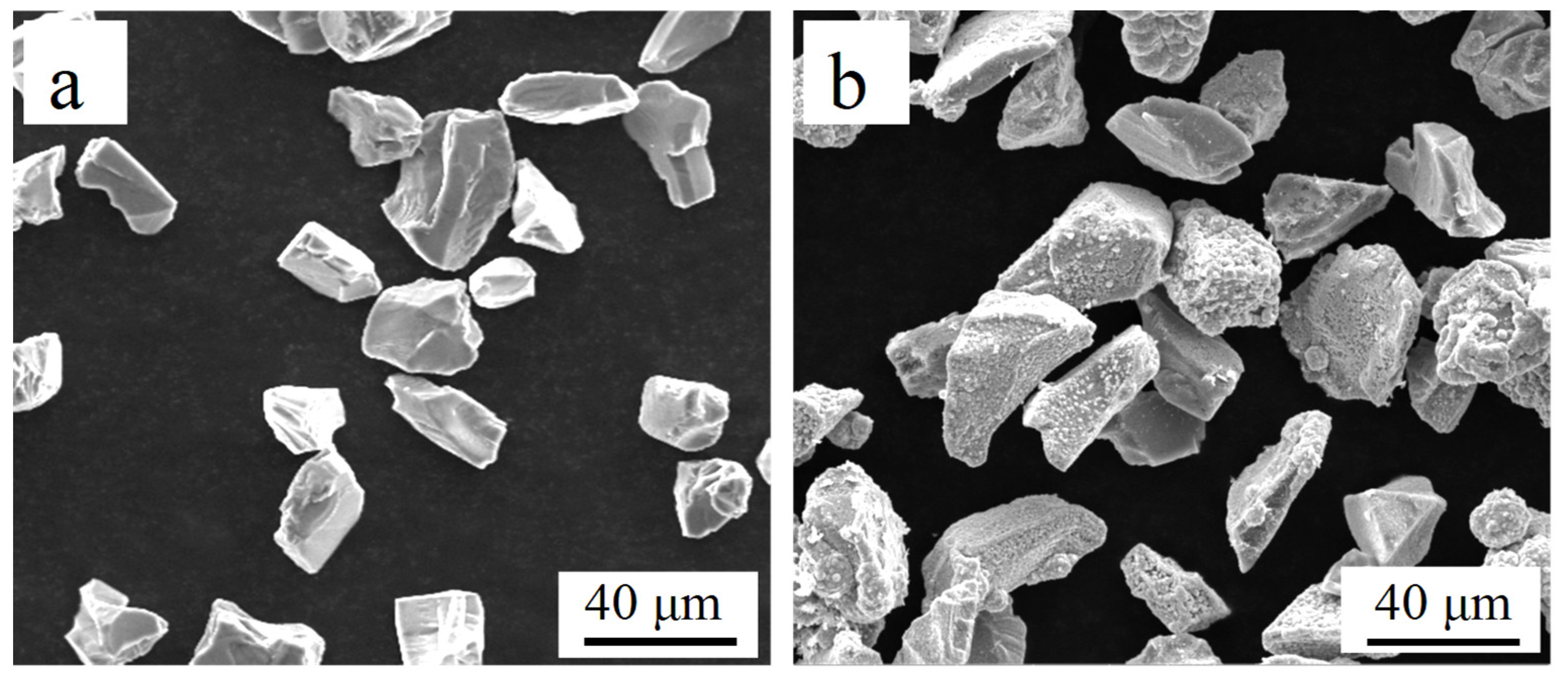
Before electroless plating, surface treatment was carried out on the SiCp. According to previous studies, pretreatment can be conducted by the traditional three-step method (coarsening, sensitization, and activation) [24,25]. After pretreatment mentioned above, electroless plating was conducted in a copper electroless bath. The composition and operating conditions of pretreatment solutions and electroless copper plating bath are displayed in Table 2. Lastly, the Cu-coated SiCp was washed with deionized water three times and dried under room temperature. Figure 1 shows the SEM images of SiCp and SiCp-Cu.
2.3. Laser Cladding Experiment
Laser cladding was performed by using the CY-WL600G type Nd-YAG pulsed laser with a wavelength of 1.06 μm. Based on the systematic experiments done previously, the laser cladding process parameters used in this study were 800 W for laser beam power, 4 mm/s for laser scan speed, and 0.2 mm for laser beam diameter. There was a 50% overlap between two adjacent laser tracks. The thickness of LCLs obtained was about 0.45 mm. After laser processing, samples were cut for cross-section and polished with abrasive paper.
The microstructures of the LCL were analyzed by 10XB-PC optical microscope (OM) from Shanghai optical instrument factory and QUATA 250 FEG series field emission scanning electron microscope (SEM) from FEI. Semiquantitative analysis of element distribution was carried out by energy dispersive spectrometer (EDS), which was equipped with SEM. The LCL phase was tested by a DX2700 diffraction analysis system (XRD) from Shanghai Precision Instruments with Cu Kα radiation and XRD patterns were taken at 2θ angles from 15° to 85° at a scanning rate of 4°/min. Also, a BUEHLER5104 microhardness tester from German Buehler was used to obtain Vickers microhardness profiles along samples cross-section up to 750 μm using a load of 50 g for 10 s. For each sample, the microhardness measurements were repeated at five locations at the center and edges of the samples. The given average values of microhardness were average values taking from all measurement points on LCLs. Wear experiments were carried out using a PRN01-04882A pin-on-disk-type tribometer from Swiss CSM Company under dry-sliding conditions. The diameter of pin samples was 3 mm. The ring of the wear couple was made of diamond. The wear conditions were given as 1.4 MPa, 0.4 m·s−1 sliding speed, and 250 m sliding distance. Wear was characterized using the mass loss of the samples and the observation of the wear scars.
3. Results and Discussion
3.1. Phase Analysis
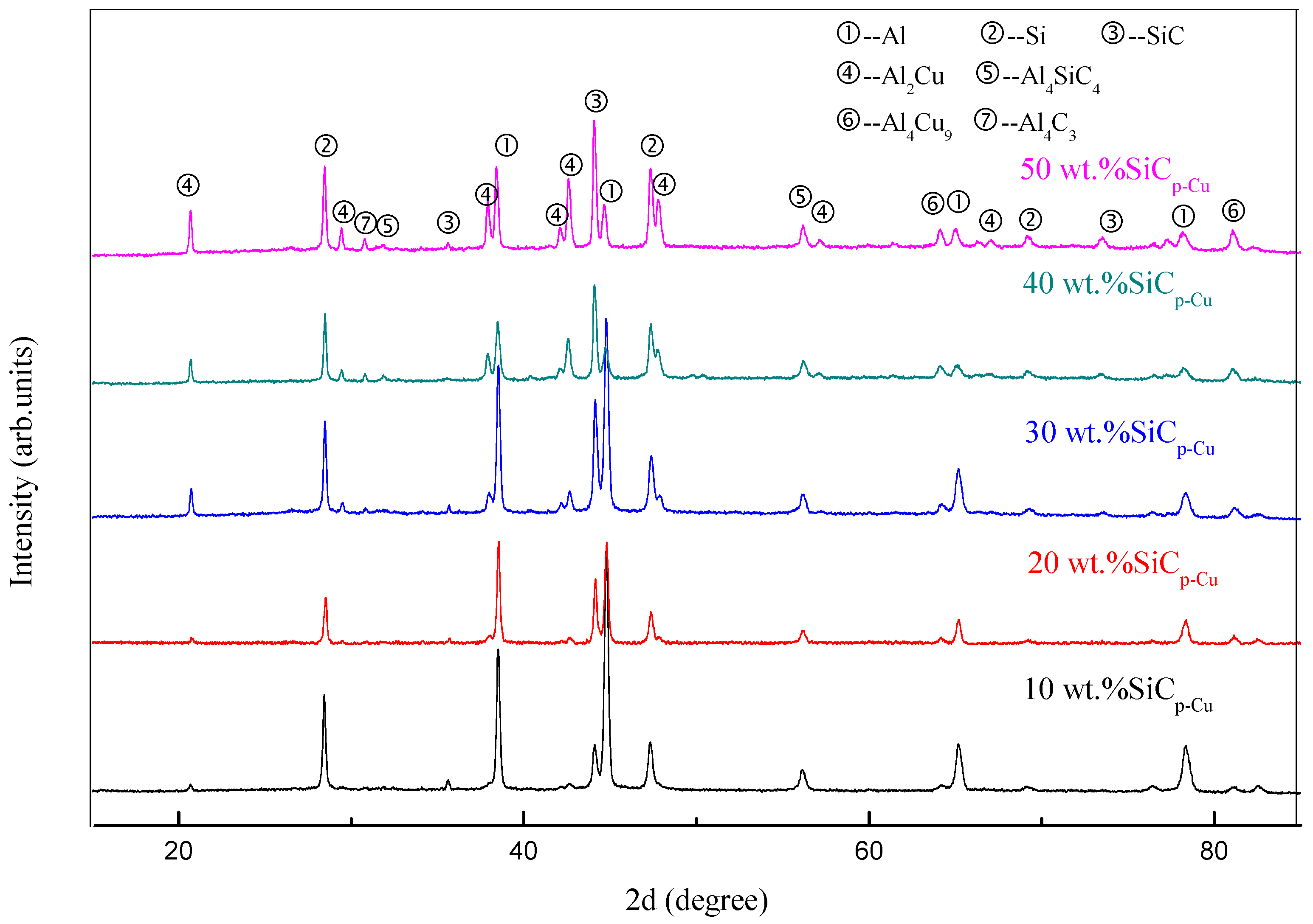
The XRD patterns of SiCp-Cu/Al–Si coatings with different SiCp-Cu content are shown in Figure 2. As can be seen, in addition to Al and Si phases, great amounts of SiCp, Al2Cu, Al4Cu9, Al4SiC4, and Al4C3 were found in the LCLs. The SiCp was the additive and Al2Cu, Al4Cu9, Al4SiC4, and Al4C3 were in situ formed novel phases. Furthermore, with increasing SiCp-Cu content, more and more Al2Cu, Al4Cu9, Al4SiC4, and Al4C3 compounds formed within the LCL and their diffraction peaks became obvious.
Table 3 describes the variation trend of 2θ values and intensities of Al peaks in LCLs with different SiCp-Cu content. At the same time, the 2θ values of the standard diffraction peak of Al are also listed. It can be seen that when the SiCp-Cu content is less than 50%, the 2θ values of Al diffraction peaks in the LCLs increase with increasing SiCp-Cu content, and all of them are larger than the standard 2θ values. When the SiCp-Cu content is 50 wt.%, the 2θ value of Al diffraction peak is smaller than the standard 2θ value. According to Bragg’s law [26], 2d sin θ = nλ (n = 1, 2, 3, …), the larger 2θ values indicate the smaller interplanar spacing of the corresponding crystal planes. It implies that the lattice deformation of the aluminum was caused by the high cooling rate and the huge residual stress during the laser cladding process.
As can be seen from Table 3, the intensity of XRD diffraction peaks of Al decreases with the increasing of SiCp-Cu content in cladding materials. Meanwhile, the half high width of the XRD diffraction peaks (FWHM) of Al increases. On the basis of the Scherrer formula [26], (where K is the Scherrer constant, D is the average thickness of the grain perpendicular to the direction of the crystal plane, B is the half high width of the diffraction peak of the measured sample, θ represents the diffraction angle, and λ is the X-ray wavelength), the increase of FWHM of Al indicates that the grain size of Al matrix decreased. It indicates that the crystal structure of the SiCp-Cu/Al-Si composite coating produced by laser cladding process was significantly refined. When the content of SiCp-Cu was 40 wt.%, the FWHM of Al was the largest, which means that the grain refinement was the most significant.
3.2. Microstructural Analysis
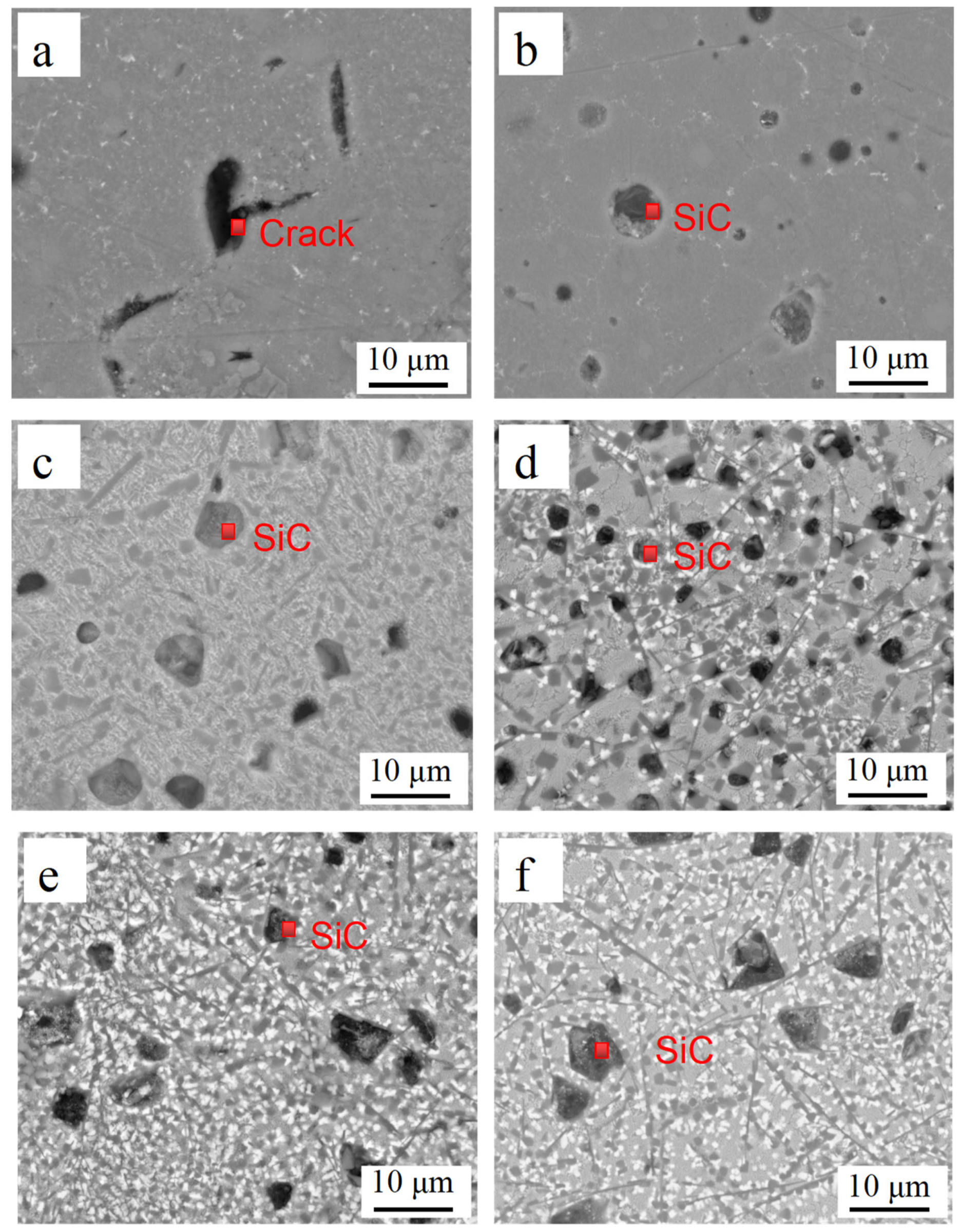
Figure 3 shows the SEM images of the cross-section of the LCLs with different SiCp-Cu content. SiCp-Cu with different sizes and shapes within the LCLs is observed. The SEM micrograph of the LCL without SiCp-Cu is shown in Figure 3a; it can be seen from the figure that the grain size is coarser than that in the coating reinforced with SiCp-Cu (Figure 3b–f). It can be seen from Figure 3a that there are cracks in the coating, and the existence of the cracks will have a negative impact on the properties of the coating. As seen in Figure 3b–f, the eutectic microstructures of the laser cladding layer become finer with increasing SiCp-Cu content due to the LCLs absorbing rapid heating and cooling during the laser cladding process and possess fast solidification [27]. In addition, these solidification rates increase with the increasing of thermal conductivity and the SiCp-Cu content, and as a result, thermal conductivity of SiCp (259 Wm−1K−1) [28] and copper (401 Wm−1K−1) is higher than that of aluminum (237 Wm−1K−1) [29].
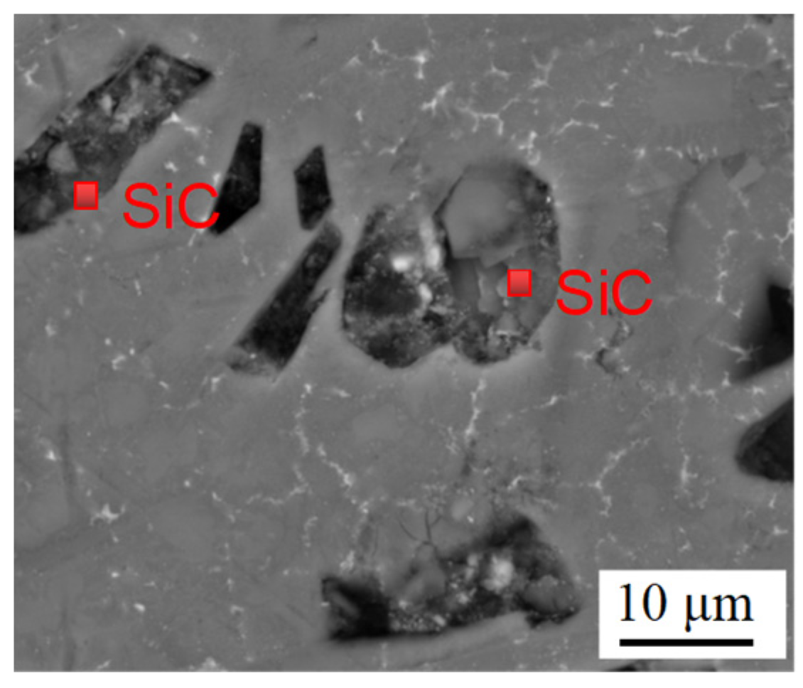
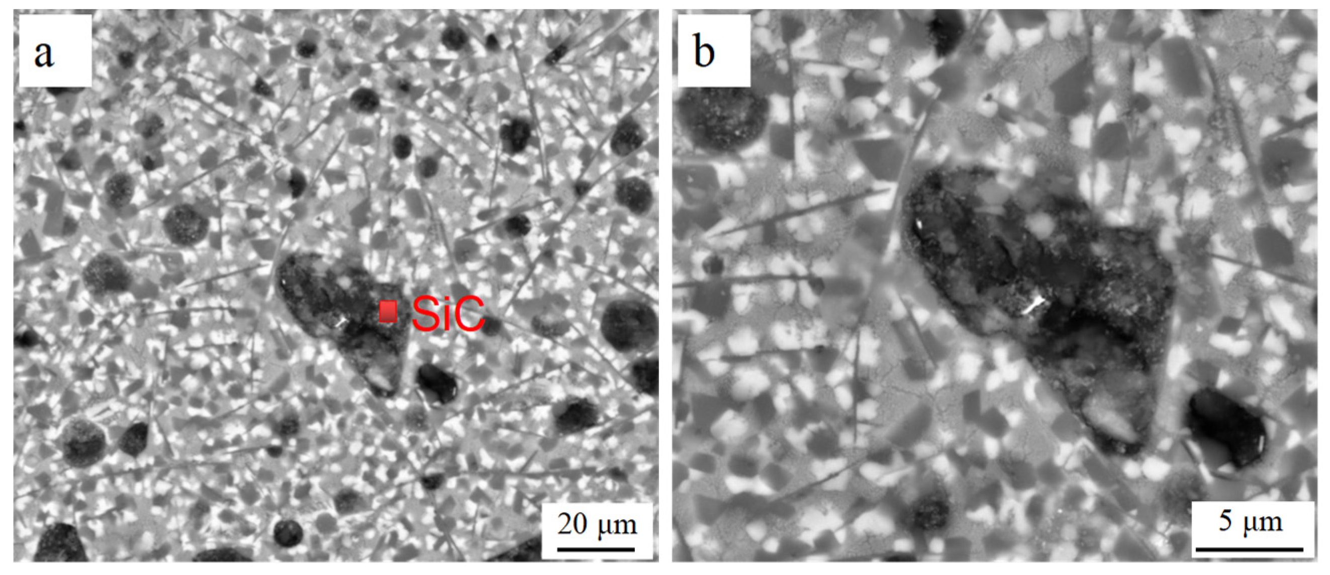
The SEM micrographs of LCL with 20 wt.% of SiCp-Cu and 20 wt.% of SiCp are demonstrated in Figure 3c and Figure 4, respectively. The SiCp remained almost unmelted and was still in an irregular polygonal shape as is shown in Figure 4. Conversely, the most SiCp-Cu was oval-shaped and had a smaller size than that of the SiCp-Cu originally used. It is indicated that the wettability of aluminum melt and SiCp can be improved by electroless copper plating process. SiCp-Cu is more likely to react with molten aluminum during the laser cladding process. It can be seen from Figure 3 that some SiCp were also in an irregular polygonal shape. This is because not all SiCp were coated entirely with copper during electroless plating as shown in Figure 1.
The microstructure of the LCL with SiCp-Cu content of 50 wt.% at a higher magnification is shown in Figure 5. It is clear that the microstructure of the LCL was mainly composed of undissolved SiCp and dark gray lump-like crystals which were distributed on the ternary eutectic of Al–Si–Cu.
The Si content of AlSi20 alloy powders used in cladding materials is 20 wt.%. At the same time, SiCp-Cu reacts with molten aluminum and forms Al4SiC4 and Si during the laser cladding process. The Si is dissolved in AlSi20, increasing its Si percentage, so that the content of Si in the molten aluminum could exceed the eutectic point. On the basis of the Al–Si binary phase diagram, the hypereutectic Al–Si matrix microstructure consisted of Al–Si eutectic and acicular primary Si crystals [17].
After electroless copper plating of SiCp, the weight gain percentage of SiCp is close to 100%, so the cladding material with SiCp-Cu content of 50 wt.% is comprised of 50 wt.% of Al–Si powder, 25 wt.% of SiCp, and 25 wt.% of Cu. The Al–Cu–Si ternary eutectic alloy is mainly composed of primary crystal Si, Al + Al2Cu binary eutectic, and Al + Si + Al2Cu ternary eutectic composition due to the high cooling rate (in the range of 103–108 K/s during the laser cladding process) [30,31,32].
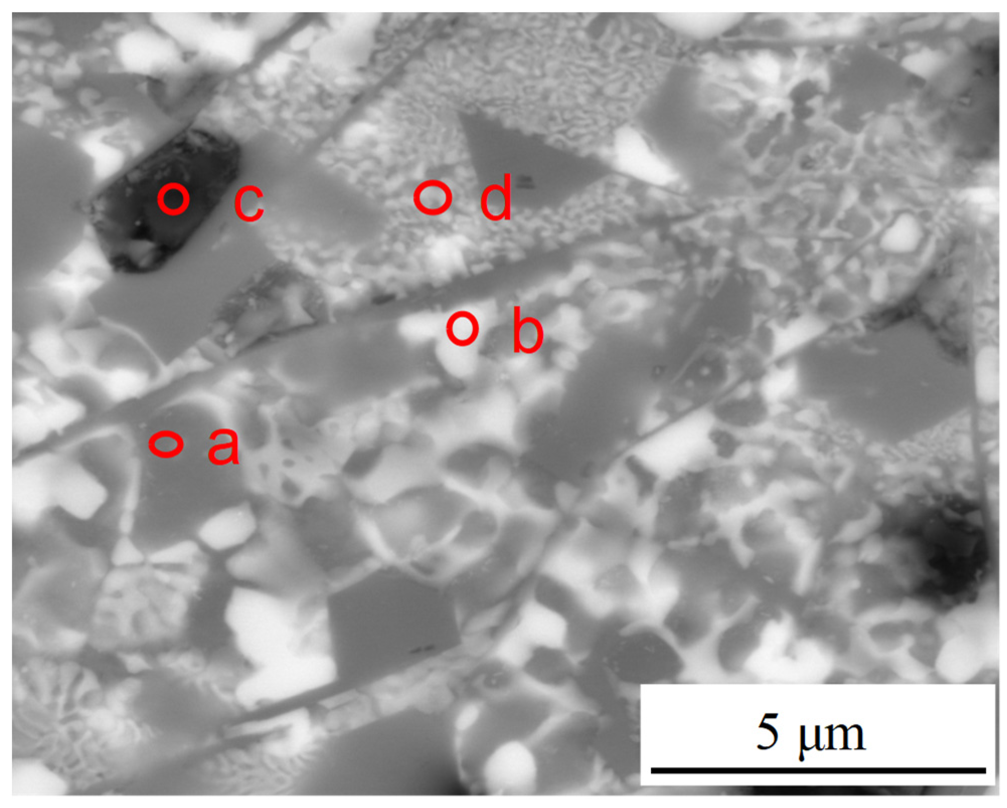
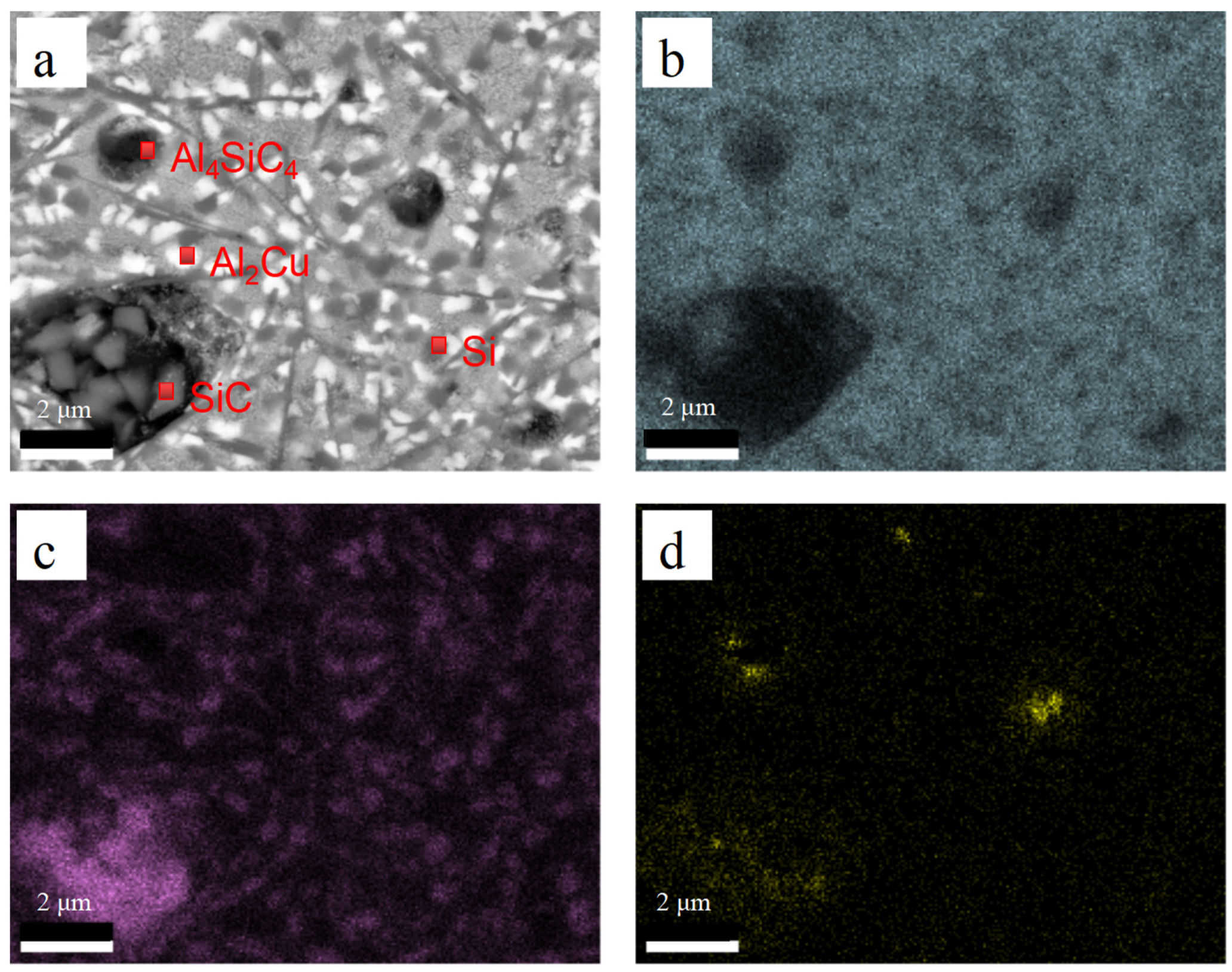
EDS analysis was performed to examine the exact composition of LCL with SiCp-Cu content of 50 wt.%. Results of EDS analysis conducted on points a–d in Figure 6 are then summarized in Table 4. Combining with the XRD phase analysis (Figure 2), it was reasonable to consider that the white lump-like crystals (point b) were Al2Cu, the black plate-like crystals (point c) were Al4SiC4, and the light gray region (point d) was Al + Al2Cu binary eutectic. The dark gray lump-like crystals (point a) in Figure 6 may be Si. Figure 7a shows the SEM image of the laser cladding layer. Figure 7b–d show the elemental maps of the LCL corresponding to the distribution of Al, Si, and C, respectively. According to that, the dark gray lump-like crystals (point a) in Figure 6 and acicular crystals can be recognized as Si phase. In summary, the microstructure of SiCp-Cu/Al–Si LCL mainly comprises undissolved SiCp, lump-like primary Si, lump-like Al2Cu, plate-like Al4SiC4, and Al–Si–Cu ternary eutectic.
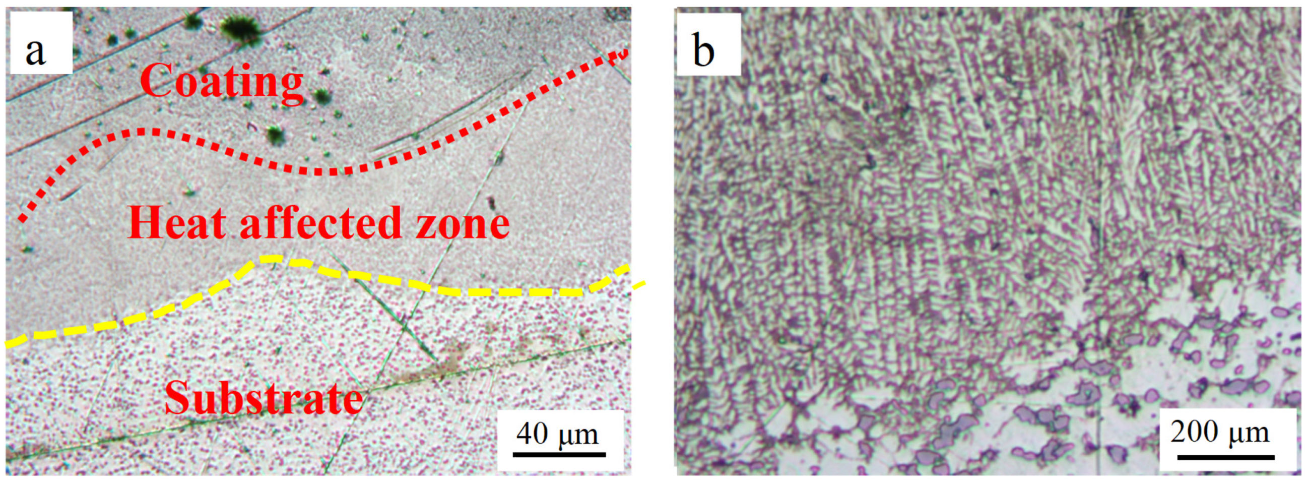
Figure 8 shows the interface between the LCL and the substrate. (The samples were cut perpendicular to the LCL direction and polished. The images were taken in the center of the LCL region.) OM images of the coating before etching are presented in Figure 8a. The curved edges of the interface between the coating and the substrate caused by the laser beam center had a higher temperature than that of the edge region. After etching the surface of the LCL using the Keller’s reagent, the OM images obtained are shown in Figure 8b. It can be seen that there are many orientated growth dendrites between the substrate and the coating, and the growth direction is substantially perpendicular to the substrate. Moreover, the LCLs show good metallurgical bonding to the substrate due to the orientated growth dendrites which are intergrown with the substrate.
3.3. Microhardness
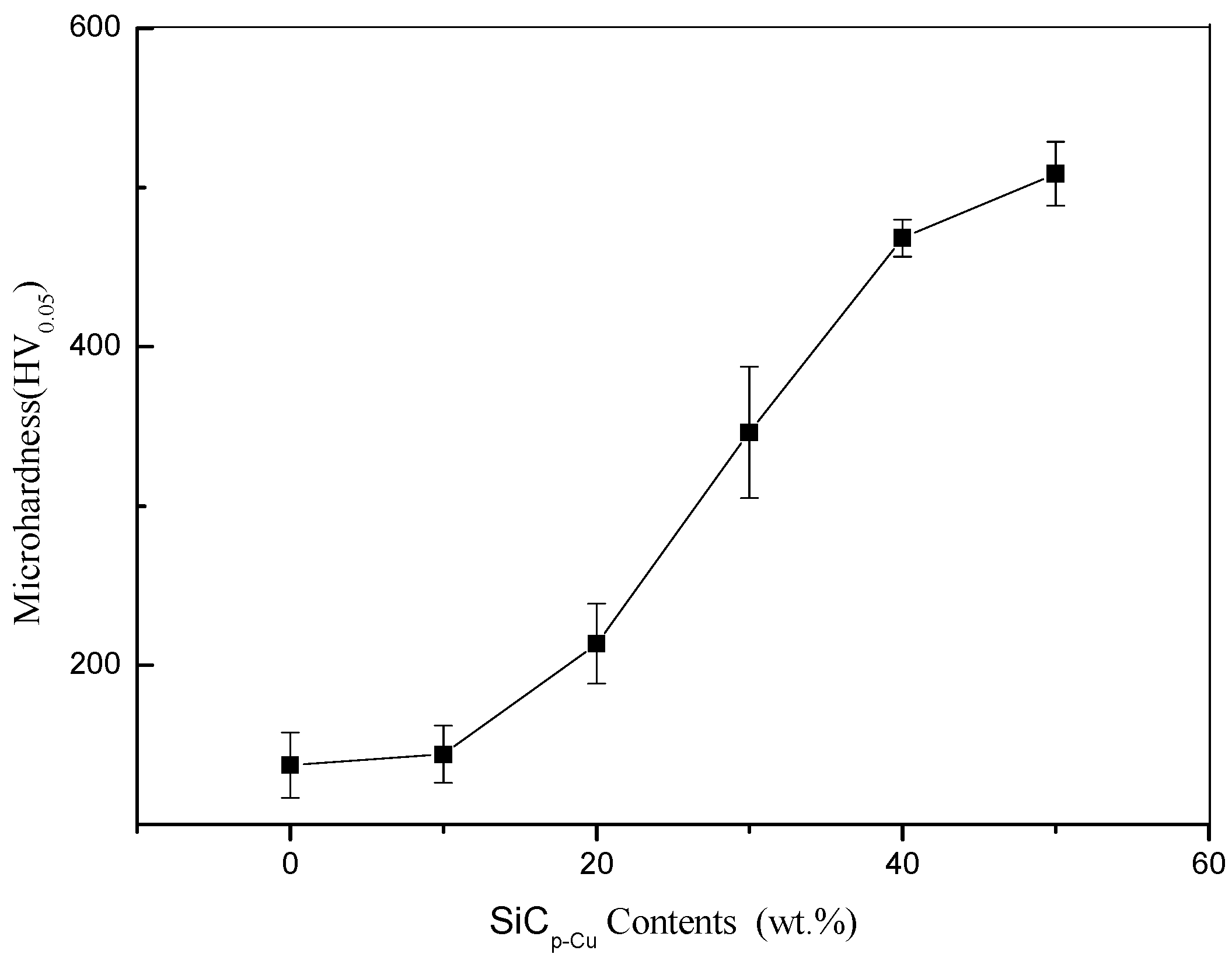
Figure 9 shows the relationship between microhardness of LCLs measured on the cross-section and the SiCp-Cu content in cladding materials. It can be seen that the average microhardness increases with the increasing SiCp-Cu content. It is noteworthy that the average microhardness of the LCL with SiCp-Cu content of 50 wt.% (508 HV0.05) is about 3.5 times higher than in the 4032 aluminum alloy substrate (145 HV0.05).
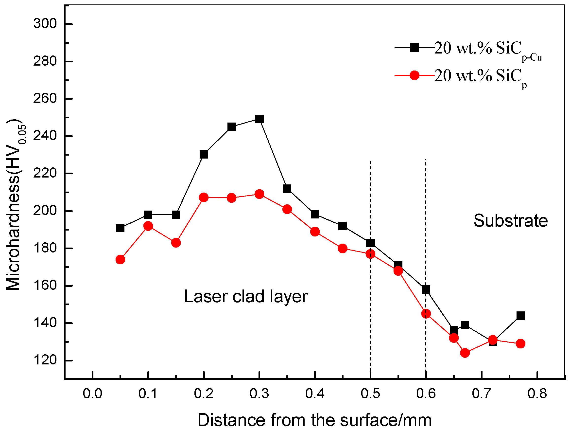
The variation of microhardness along depth direction of the LCLs is shown in Figure 10. As can be seen, the microhardness of LCL reinforced with SiCp-Cu ranges from 190 HV0.05 to 250 HV0.05, and the average value is 210 HV0.05. The microhardness of the other LCL reinforced with SiCp is between 170 and 209 HV0.05 and the average value is 192 HV0.05. This indicates that electroless copper plating on SiCp can improve the microhardness of SiCp/Al–Si composite coating.
The two reasons for the high microhardness of the SiCp/Al–Si composite coating are as follows: Firstly, the increase in microhardness is mainly attributed to the dissolution of SiCp-Cu in the LCLs and the resulting increase in the numbers of Al4SiC4 (1200 HV [30]) and Al–Cu intermetallic (microhardness of Al2Cu in the range of 400–600 HV0.2 [33]) formed on resolidification. Secondly, the effects of laser rapid heating and cooling cause a finer and harder microstructure.
3.4. Wear Properties
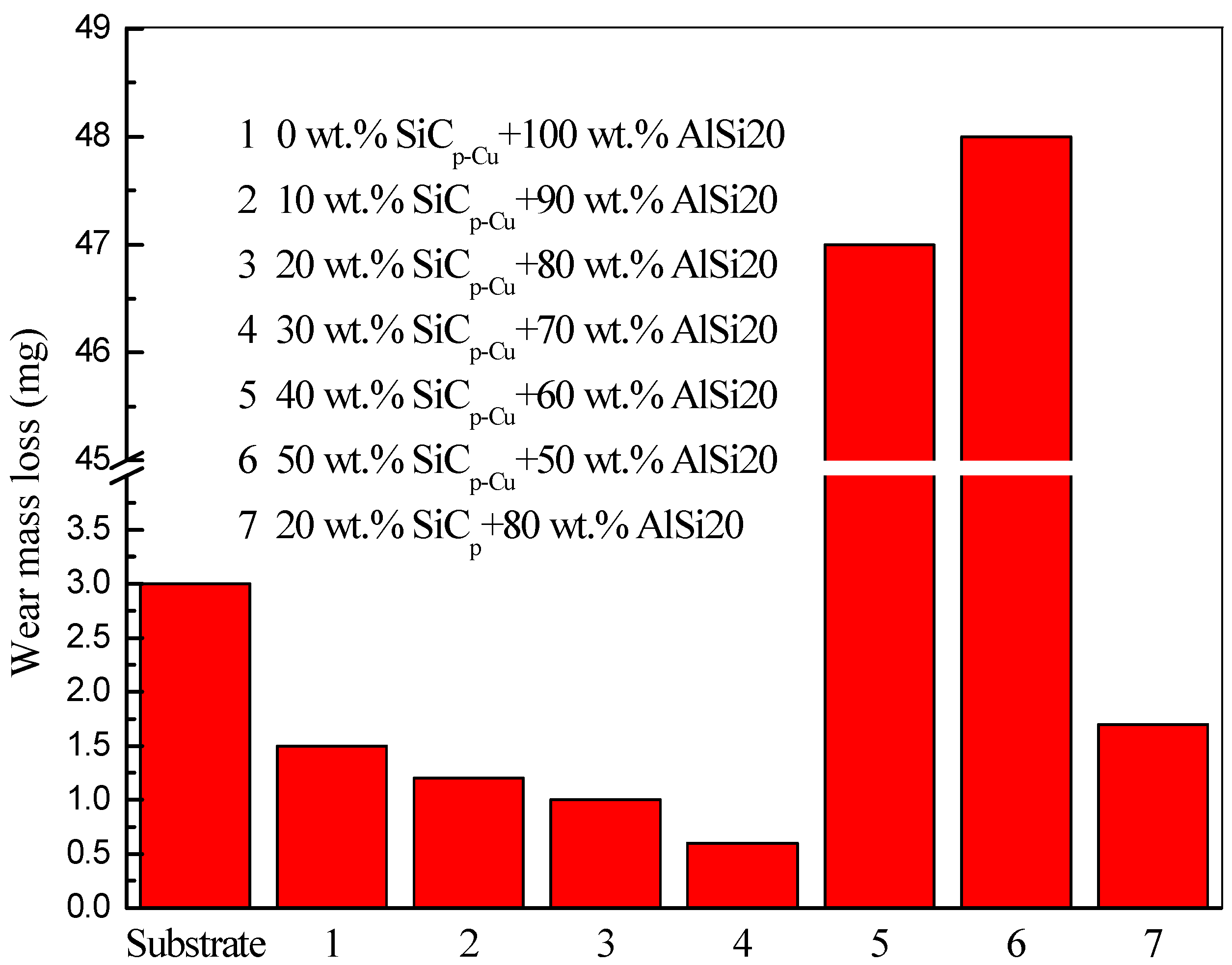
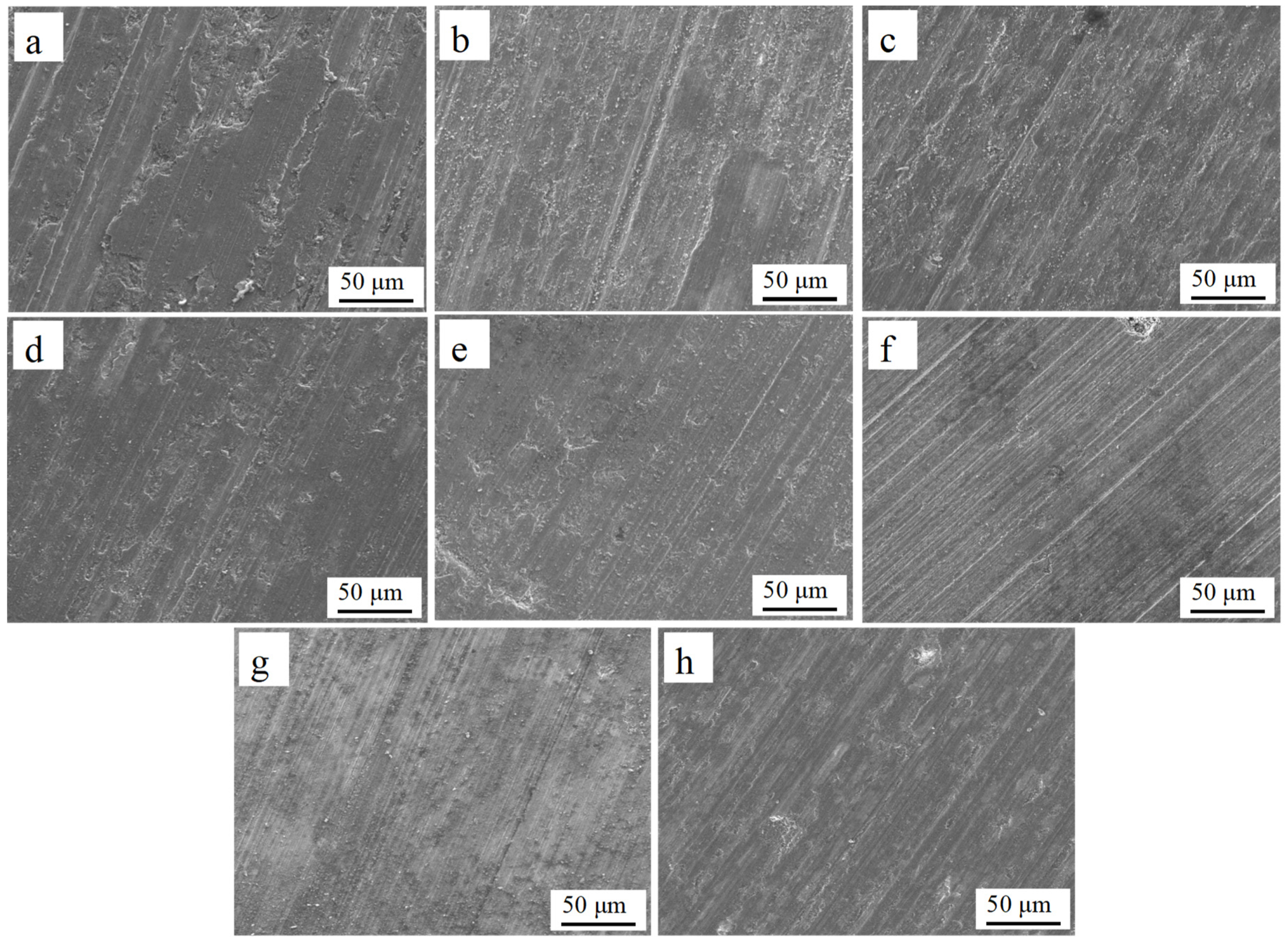
The wear mass loss of all samples is presented in Figure 11. It can be seen that the wear mass loss showed a decrease as the content of SiCp-Cu increased from 0 to 30 wt.% and was less than that of the substrate. On the contrary, the LCLs with 40–50 wt.% of SiCp-Cu had more wear mass loss compared with the substrate. The wear mass loss of LCL with a SiCp content of 20 wt.% was less than that of the substrate, but more than that of the LCL with a SiCp-Cu content of 20 wt.%. Figure 12 shows the SEM images of the worn surface of all samples. In Figure 12a, it is clearly observed that the worn surface of the substrate was easily deformed plastically under stress and shows parallel grooves. The grooves on the worn surface of the LCLs became narrower and shallower as the content of SiCp-Cu increased from 0 to 30 wt.%, as shown in Figure 12b–e. The grooves on the worn surface of the LCL with 20 wt.% of SiCp were deeper and wider compared with those of the LCL with 20 wt.% of SiCp-Cu. Nevertheless, it can be seen from Figure 12f–g that the grooves became deeper as the content of SiCp-Cu increased from 40 to 50 wt.%. Therefore, the LCL with 30 wt.% of SiCp-Cu exhibits the best wear resistance, and electroless copper plating on SiCp can improve the wear resistance of SiCp/Al–Si composite coating. Improvement of wear resistance of the SiCp/Al–Si composite coating must be attributed to the presence of Al4SiC4 and Al–Cu intermetallic and finer microstructure. When the content of SiCp-Cu reaches 40 wt.% or more, the content of AlSi20 decreases evidently, resulting in the difficulty of SiCp-Cu packed by Al–Si alloy. The SiCp-Cu were easily separated from the worn surface during the wear test and tended to plow the LCLs seriously. Consequently, the decrease of the wear resistance of the LCLs with high SiCp-Cu content is observed.
4. Conclusions
- 1)
- SiCp-reinforced aluminum matrix composite coatings with high microhardness can be successfully obtained on the surface of 4032 aluminum alloy by the laser cladding process. Electroless copper plating on SiCp can improve the properties of SiCp/Al–Si composite coating.
- 2)
- The microstructure of the SiCp-Cu/Al–Si laser cladding layer consisted of undissolved SiCp, lump-like primary Si, lump-like Al2Cu, plate-like Al4SiC4, and Al–Si–Cu ternary eutectic. Meanwhile, the microstructure became finer with the increasing of SiCp-Cu content due to the fast solidification.
- 3)
- The microhardness of the laser cladding layer increased with the increasing of SiCp-Cu content. It increased from 145 HV0.05 to 508 HV0.05 due to the presence of Al4SiC4 and Al–Cu intermetallic and finer microstructure.
- 4)
- The wear resistance of the laser cladding layer increased with the increasing of SiCp-Cu content. The LCL reinforced with a SiCp-Cu content of 30 wt.% exhibits the best wear resistance. When the SiCp-Cu content reached 40-50 wt.%, the wear resistance of the LCLs decreased due to the spalling of SiCp-Cu during the wear test.
Author Contributions
Conceptualization, Y.L. and G.L.; methodology, Y.L.; software, Y.L.; validation, Y.L., G.L., and W.J.; formal analysis, Y.L.; investigation, Y.L.; resources, G.L.; data curation, Y.L.; writing—original draft preparation, Y.L.; writing—review and editing, Y.L.; visualization, Y.L.; supervision, Y.L.; project administration, Y.L.; funding acquisition, G.L.
Funding
This work is supported by National Natural Science Foundation of China (51021063).
Acknowledgments
The authors thank Hongwei Liu for providing 4032 aluminum alloy for us.
Conflicts of Interest
The authors declare no conflict of interest.
References
- Chi, Y.M.; Gu, G.C.; Yua, H.J.; Chen, C.Z. Laser surface alloying on aluminum and its alloys: A review. Opt. Laser Eng. 2018, 100, 23–37. [Google Scholar] [CrossRef]
- Jia, Z.W.; Sun, W.C.; Guo, F.; Dong, Y.R.; Liu, X.J. Microstructure, friction and corrosion resistance properties of a Ni–Co–Al2O3 composite coating. RSC Adv. 2018, 22, 12138–12145. [Google Scholar] [CrossRef]
- Watkins, K.G.; McMahon, M.A.; Steen, W.M. Microstructure and corrosion properties of laser surface processed aluminium alloys: A review. Mater. Sci. Eng. 1997, 231, 56–61. [Google Scholar] [CrossRef]
- Kawalec, M.; Przestacki, D.; Bartkowiak, K.; Jankowiak, M. Laser assisted machining of aluminium composite reinforced by SiC particle. Int. Congr. Appl. Lasers Electro Opt. 2008, 1906, 895–900. [Google Scholar]
- Wang, C.L.; Gao, Y.; Zeng, Z.C.; Fu, Y.K. Effect of rare-earth on friction and wear properties of laser cladding Ni-based coatings on 6063Al. J. Alloy. Compd. 2017, 727, 278–285. [Google Scholar] [CrossRef]
- Anandkumar, R.; Almeida, A.; Vilar, R.; Ocelík, V.; de Hosson, J.T.M. Influence of powder particle injection velocity on the microstructure of Al–12Si/SiCp coatings produced by laser cladding. Surf. Coat. Technol. 2009, 204, 285–290. [Google Scholar] [CrossRef]
- Singh, A.; Ramakrishnan, A.; Baker, D.; Biswas, A.; Dinda, G.P. Laser metal deposition of nickel coated Al 7050 alloy. J. Alloy. Compd. 2017, 719, 151–158. [Google Scholar] [CrossRef]
- Xu, N.; Sarkar, D.K.; Chen, X.G.; Zhang, H.; Tong, W.P. Superhydrophobic copper stearate/copper oxide thin films by a simple one-step electrochemical process and their corrosion resistance properties. RSC Adv. 2016, 42, 35466–35478. [Google Scholar] [CrossRef]
- Hamid, Z.A.; Elkhair, M.T.A. Development of electroless nickel–phosphorous composite deposits for wear resistance of 6061 aluminum alloy. Mater. Lett. 2002, 57, 720–726. [Google Scholar] [CrossRef]
- Bao, Y.Q.; Gawne, D.T.; Gao, J.; Zhang, T.; Cuenca, B.D.; Alberdi, A. Thermal-spray deposition of enamel on aluminium alloys. Surf. Coat. Technol. 2013, 232, 150–158. [Google Scholar] [CrossRef]
- Lu, J.Q.; Wei, G.Y.; Yu, Y.D.; Guo, C.F.; Li, J. Aluminum alloy AA2024 anodized from the mixed acid system with enhanced mechanical properties. Surf. Interface Anal. 2018, 13, 46–50. [Google Scholar] [CrossRef]
- Liu, W.H.; Liu, W.B.; Bao, A.L. Microstructure and Properties of Ceramic Coatings on 7N01 Aluminum Alloy by micro-Arc Oxidation. Procedia Eng. 2012, 27, 828–832. [Google Scholar] [CrossRef]
- Riquelme, A.; Rodrigo, P.; Otero, E.; Rams, J. Effect of alloy elements added on microstructure and hardening of Al/SiC laser clad coatings. J. Alloy. Compd. 2017, 727, 671–682. [Google Scholar] [CrossRef]
- Riquelme, A.; Rodrigo, P.; Rams, J. Analysis and optimization of process parameters in Al-SiCp laser cladding. Opt. Laser. Eng. 2016, 78, 165–173. [Google Scholar] [CrossRef]
- Podlesak, H.; Schnick, T.; Pawlowski, L.; Steinhäuser, S.; Wielage, B. Microscopic study of Al–SiC particulate composites processed by laser shocks. Surf. Coat. Technol. 2000, 124, 32–38. [Google Scholar] [CrossRef]
- Lee, H.K. Effects of the cladding parameters on the deposition efficiency in pulsed Nd:YAG laser cladding. J. Mater. Process. Technol. 2008, 202, 321–327. [Google Scholar] [CrossRef]
- Sun, R.L.; Lei, Y.W. Microstructure and hardness of laser clad SiCp–Al composite coatings on Al alloys. Mater. Lett. 2008, 62, 3272–3275. [Google Scholar] [CrossRef]
- Hegge, H.J.; Boetje, J.; de Hossonc, J.T.H.M. Oxidation effects during laser cladding of aluminium with SiC/Al powders. J. Mater. Sci. 1990, 25, 2335–2338. [Google Scholar] [CrossRef] [Green Version]
- Anandkumar, R.; Almeida, A.; Colaço, R.; Vilar, R.; de Hosson, J.T.M. Microstructure and wear studies of laser clad Al-Si/SiC(p) composite coatings. Surf. Coat. Technol. 2007, 201, 9497–9505. [Google Scholar] [CrossRef]
- Viala, J.C.; Fortier, P.; Bouix, J. Stable and metastable phase equilibria in the chemical interaction between aluminium and silicon carbide. J. Mater. Sci. 1990, 25, 1842–1850. [Google Scholar] [CrossRef]
- Oden, L.L.; Mccune, R.A. Phase equilibria in the Al-Si-C system. Metall. Trans. B 1987, 18, 2005–2014. [Google Scholar] [CrossRef]
- Zhou, X.B.; de Hosson, J.T.M. Reactive wetting of liquid metals on ceramic substrates. Acta Mater. 1995, 44, 421–426. [Google Scholar] [CrossRef]
- Ureña, A.; Rodrigo, P.; Gil, L.; Escalera, M.D.; Baldonedo, J.L. Interfacial reactions in an Al-Cu-Mg (2009)/SiCw composite during liquid processing Part II Arc welding. J. Mater. Sci. 2001, 36, 429–439. [Google Scholar] [CrossRef]
- Chen, Y.J.; Cao, M.S.; Xu, Q.; Zhu, J. Electroless nickel plating on silicon carbide nanoparticles. Surf. Coat. Technol. 2003, 172, 90–94. [Google Scholar] [CrossRef]
- Zhu, S.L.; Tang, L.; Cui, Z.D.; Wei, Q.; Yang, X.J. Preparation of copper-coated β-SiC nanoparticles by electroless plating. Surf. Coat. Technol. 2011, 205, 2985–2988. [Google Scholar] [CrossRef]
- Chang, F.; Gu, D.D.; Dai, D.H.; Yuan, P.P. Selective laser melting of in-situ Al4SiC4 + SiC hybrid reinforced Al matrix composites: Influence of starting SiC particle size. Surf. Coat. Technol. 2015, 272, 15–24. [Google Scholar] [CrossRef]
- de Hosson, J.T.M.; Noordhuis, J. Mechanical properties and microstructure of laser treated Al-Cu-Mg alloys. Mater. Sci. Forum 1994, 163–165, 405–410. [Google Scholar] [CrossRef]
- Guo, H.; Han, Y.Y.; Zhang, X.M.; Jia, C.C.; Xu, J. Microstructure and thermophysical properties of SiC/Al composites mixed with diamond. Trans. Nonferrous Met. Soc. China 2015, 25, 170–174. [Google Scholar] [CrossRef]
- van Otterloo, J.L.d.M.; de Hosson, J.T.M. Laser treatment of aluminum/copper alloys: A mechanical enhancement. Scripta Metall. 1994, 30, 493–498. [Google Scholar] [CrossRef]
- de Wilde, J.; Froyen, L. Microstructures observed during directional solidification along the univariant eutectic reaction in a ternary Al-Cu-Si alloy. Mater. Sci. Forum 2006, 508, 51–56. [Google Scholar] [CrossRef]
- Ferreira, I.L.; Moutinho, D.J.; Gomes, L.G.; Rocha, O.L.; Goulart, P.R.; Garcia, A. Microstructural Development in a Ternary Al-Cu-Si Alloy during Transient Solidification. Mater. Sci. Forum 2010, 636–637, 643–650. [Google Scholar] [CrossRef]
- Agarwal, A.; Dahotre, N.B. Laser surface engineering of steel for hard refractory ceramic composite coating. Int. J. Refract. Met. Hard Mater. 1999, 17, 283–293. [Google Scholar] [CrossRef]
- Dubourg, L.; Pelletier, H.; Vaissiere, D.; Hlawka, F.; Cornet, A. Mechanical characterisation of laser surface alloyed aluminium-copper systems. Wear 2002, 253, 1077–1085. [Google Scholar] [CrossRef]
Figure 1.
The SEM image of (a) uncoated SiCp, (b) SiCp-Cu.

Figure 2.
XRD results of laser cladding layer with different SiCp-Cu content.

Figure 3.
SEM images of laser cladding layer with different content of SiCp-Cu (a) 0 wt.%; (b) 10 wt.%; (c) 20 wt.%; (d) 30 wt.%; (e) 40 wt.%; (f) 50 wt.%.
Figure 3.
SEM images of laser cladding layer with different content of SiCp-Cu (a) 0 wt.%; (b) 10 wt.%; (c) 20 wt.%; (d) 30 wt.%; (e) 40 wt.%; (f) 50 wt.%.

Figure 4.
SEM images of a laser cladding layer with a SiCp content of 20 wt.%.

Figure 5.
Microstructures of a laser cladding layer with a SiCp-Cu content of 50 wt.%.

Figure 6.
Microstructure of a laser cladding layer with a SiCp-Cu content of 50 wt.%.

Figure 7.
Distribution of aluminium (b), silicon (c), and carbon (d) of microstructure of the laser cladding layer with a SiCp-Cu content of 50 wt.% (a).
Figure 7.
Distribution of aluminium (b), silicon (c), and carbon (d) of microstructure of the laser cladding layer with a SiCp-Cu content of 50 wt.% (a).

Figure 8.
Interface morphologies of SiCp-Cu/Al–Si laser cladding before etching (a) and after etching (b).
Figure 8.
Interface morphologies of SiCp-Cu/Al–Si laser cladding before etching (a) and after etching (b).

Figure 9.
Relationship between microhardness and the SiCp-Cu content.

Figure 10.
Distribution curves of microhardness along depth direction of SiCp/Al–Si laser cladding layer.
Figure 10.
Distribution curves of microhardness along depth direction of SiCp/Al–Si laser cladding layer.

Figure 11.
Wear mass loss of all samples.

Figure 12.
The worn surface morphologies of the substrate and laser cladding coatings with the different SiCp contents; (a) substrate; (b) 100% AlSi20; (c) 10 wt.% SiCp-Cu + 90 wt.% AlSi20; (d) 20 wt.% SiCp-Cu + 80 wt.% AlSi20; (e) 30 wt.% SiCp-Cu + 70 wt.% AlSi20; (f) 40 wt.% SiCp-Cu + 60 wt.% AlSi20; (g) 50 wt.% SiCp-Cu + 50 wt.% AlSi20; (h) 20 wt.% SiCp + 80 wt.% AlSi20.


Table 1.
Composition ratio of laser cladding material.
| Number | SiCp-Cu (wt.%) | SiCp (wt.%) | Al (wt.%) |
|---|---|---|---|
| 1 | 0 | / | 100 |
| 2 | 10 | / | 90 |
| 3 | 20 | / | 80 |
| 4 | 30 | / | 70 |
| 5 | 40 | / | 60 |
| 6 | 50 | / | 50 |
| 7 | / | 20 | 80 |
Table 2.
Composition and operating conditions of pretreatment solutions and electroless copper plating bath.
Table 2.
Composition and operating conditions of pretreatment solutions and electroless copper plating bath.
| Roughening Solution | Sensitizing Solution | Activating Solution | Plating Bath | |
|---|---|---|---|---|
| HF (40%) | 1.15 M | / | / | / |
| HCl (37%) | / | 1.20 M | 0.24 M | / |
| SnCl2 · 2H2O | / | 0.22 M | / | / |
| PdCl2 | / | / | 2.82 mM | / |
| CuSO4 · 5H2O | / | / | / | 40 mM |
| NiSO4 · 6H2O | / | / | / | 5.42 mM |
| NaH2PO4 · H2O | / | / | / | 0.38 M |
| Na3C6H5O7 · 2H2O | / | / | / | 0.14 M |
| H3BO3 | / | / | / | 0.48 M |
| T (°C) | 25~30 | 25~30 | 25~30 | 65 |
| pH | / | / | / | 10.5 |
| t (min) | 15 | 15 | 15 | 10 |
Table 3.
Intensity variation of Al diffraction peak of laser cladding with different SiCp-Cu mass fraction.
Table 3.
Intensity variation of Al diffraction peak of laser cladding with different SiCp-Cu mass fraction.
| SiCp-Cu (wt.%) | 2θ (°) | Intensity | FWHM | 2θ (°) | Intensity | FWHM |
|---|---|---|---|---|---|---|
| standard | 38.47 | 44.72 | ||||
| 10 | 38.49 | 1080 | 0.240 | 44.77 | 1817 | 0.262 |
| 20 | 38.56 | 1027 | 0.250 | 44.81 | 1005 | 0.283 |
| 30 | 38.53 | 1134 | 0.262 | 44.76 | 1467 | 0.284 |
| 40 | 38.48 | 449 | 0.294 | 44.74 | 226 | 0.356 |
| 50 | 38.41 | 630 | 0.252 | 44.66 | 326 | 0.304 |
Table 4.
EDS analysis of laser cladding layer with a SiCp-Cu content of 50 wt.% (corresponding to a, b, c, d points in Figure 6).
Table 4.
EDS analysis of laser cladding layer with a SiCp-Cu content of 50 wt.% (corresponding to a, b, c, d points in Figure 6).
| Detection Positions | Al (wt.%) | Si (wt.%) | C (wt.%) | Cu (wt.%) |
|---|---|---|---|---|
| a | 26.03 | 50.01 | 2.40 | 21.56 |
| b | 45.01 | 10.80 | 3.87 | 40.32 |
| c | 32.30 | 11.15 | 36.94 | 20.62 |
| d | 55.74 | 4.09 | 2.37 | 37.81 |
© 2019 by the authors. Licensee MDPI, Basel, Switzerland. This article is an open access article distributed under the terms and conditions of the Creative Commons Attribution (CC BY) license (http://creativecommons.org/licenses/by/4.0/).
Share and Cite
MDPI and ACS Style
Liu, Y.; Li, G.; Jiang, W. Effects of Cu-Coated SiC Content on Microstructure and Properties of Laser Cladding SiCp/Al–Si Composite Coatings. Materials 2019, 12, 1537. https://doi.org/10.3390/ma12091537
AMA Style
Liu Y, Li G, Jiang W. Effects of Cu-Coated SiC Content on Microstructure and Properties of Laser Cladding SiCp/Al–Si Composite Coatings. Materials. 2019; 12(9):1537. https://doi.org/10.3390/ma12091537
Chicago/Turabian StyleLiu, Yang, Guodong Li, and Wenting Jiang. 2019. "Effects of Cu-Coated SiC Content on Microstructure and Properties of Laser Cladding SiCp/Al–Si Composite Coatings" Materials 12, no. 9: 1537. https://doi.org/10.3390/ma12091537
Note that from the first issue of 2016, this journal uses article numbers instead of page numbers. See further details here.