Densification Mechanism of Soft Magnetic Composites Using Ultrasonic Compaction for Motors in EV Platforms

1
EV Components & Materials R&D Group, Korea Institute of Industrial Technology, Gwangju 61012, Korea
2
Department of Electrical Engineering, Chonnam National University, Gwangju 61186, Korea
3
Robotics and Virtual Engineering, Korea University of Science and Technology, Daejeon 34113, Korea
*
Author to whom correspondence should be addressed.
Materials 2019, 12(5), 824; https://doi.org/10.3390/ma12050824
Submission received: 22 January 2019
/
Revised: 28 February 2019
/
Accepted: 3 March 2019
/
Published: 11 March 2019
(This article belongs to the Special Issue Mechanical and Physical Properties of Metallic Composites)
Abstract
:In this paper, the densification mechanism of ultrasonic compaction was analyzed using a force balance model. Ultrasonic compaction is quite a promising way to solve the lower mechanical property problem of green compact in the compaction process, although it has some obstacles to overcome for its various applications. Our model proposes that the resultant density is achieved as the applied and resistance forces reach the equilibrium state. Based on the proposed model, the ultrasonic compaction increases the density of green compact by reducing the internal friction between the powder and compaction die, as well as the internal friction among particles themselves. It was also found that during the powder compaction, the ultrasonic vibration mostly contributes to slipping and the rearrangement of the particles.
1. Introduction
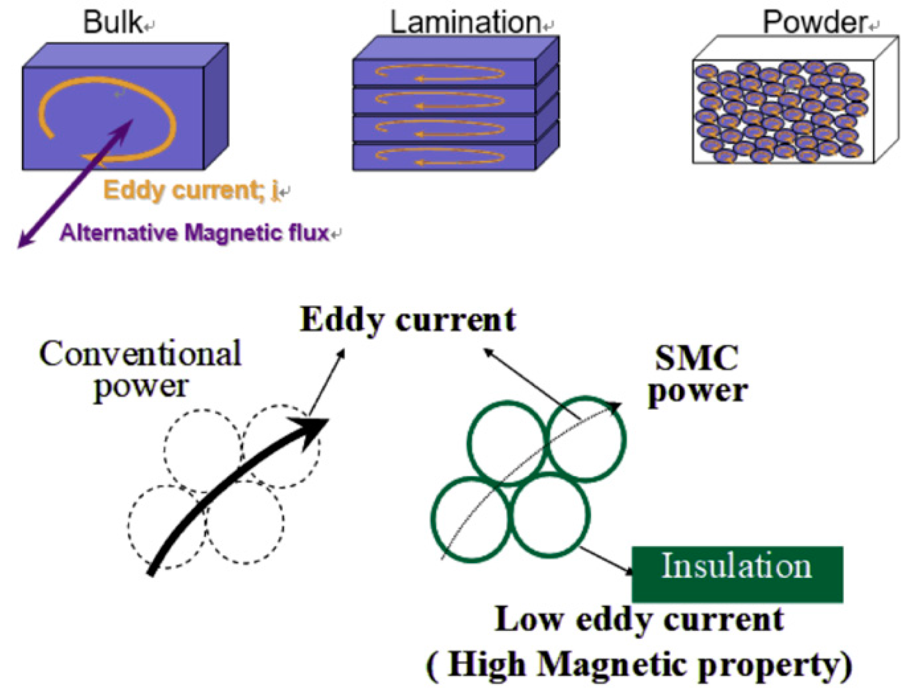
During recent years, interest in the study of the soft magnetic composites (SMCs) has increased in the magnetic and electric industries. SMC materials are basically pure iron powder particles coated with very thin electrically insulating layers. As Figure 1 shows, the insulating layer restricts the eddy current, which is generated by an alternating magnetic field to mainly travel within each individual particle. Due to eddy current restriction, SMC materials provide new opportunities to design compact, light, and cost-efficient solutions for high-performance motors [1,2,3,4].
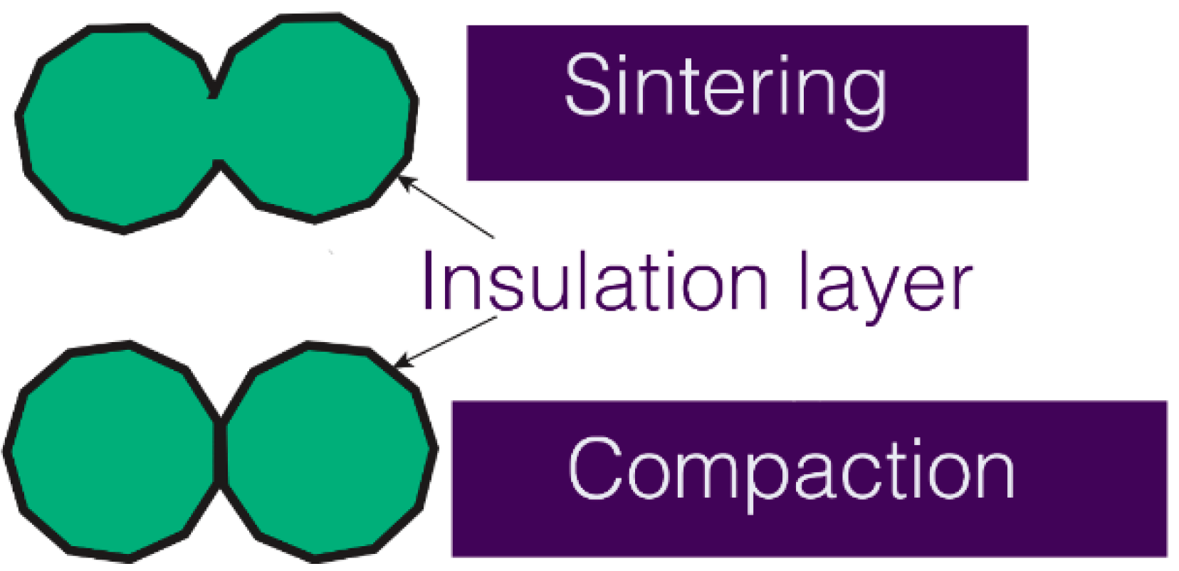
In conventional powder metallurgy processing, the parts are sintered after compaction. Sintering is a high-temperature heat treatment which develops the bonds between the powder particles and enhances their mechanical performance. However, SMC powders cannot be sintered, because they reduce the eddy current. If the magnetic flux changes in the magnetic substance, an electromotive force is generated—a swirl of current flows through the magnetron. This is called an eddy current, which consumes the mechanical energy of the driving part in Joule heating, thus reducing efficiency. To reduce this, the particles should not be bonded to each other, as shown in Figure 1. The temperatures involved would cause the insulation coating to break down, giving a poor electrical performance as the particles would bond to each other as shown in Figure 2 [5,6]. Therefore, in order to form an SMC, only the compaction method is applied.
It is well known that high-frequency vibrations, such as ultrasonic vibration, reduce particle friction [7,8,9]. Researchers proposed the usage of ultrasonic vibration during the powder compaction process to increase the density and reduce the internal friction without the increase in compaction pressure. J. Tsujino et al. reported the ultrasonic vibration press of copper and piezoelectric ceramic powder in a vacuum condition [10,11], and O.L. Khasanov et al. reported the ultrasonic compaction of ceramic nano-powder [12]. Both studies made the following conclusions—the ultrasonic compaction during the ceramic nano-powder compaction (a) lowered lateral pressure to a greater degree in a low compaction pressure condition, (b) more effectively decreased an elastic after-effect in a high-pressure environment, and (c) improved the green compact quality [13,14,15].
According to the published literature, one of the effective methods for powder compaction is ultrasonic-assisted compaction under a pressure of 250 MPa, which may potentially be applicable to massive powder metallurgy manufacture processes [16].
However, the ultrasonic compaction method faces a problem that limits its wider application. Due to an unknown mechanism, the high densification phenomenon is generally accepted without clear explanations. The aim of this research, therefore, is to investigate the relationship between low internal friction forces and the high densification of powders using a force balance model. We expect that our proposed model will contribute to the wider usage of ultrasonic compaction and its successful industrialization.
In this paper, the reduction in friction and the improvement in resultant density are studied as functions of compression pressure, vibration amplitude/frequency, and input power. Through this experiment, fundamental information such as the densification mechanism under ultrasonic action and the optimum design parameter for high densification is determined. It is found that the input power needed to drive the ultrasonic vibration system is the governing parameter for obtaining the high density results of an SMC specimen.
2. Materials and Methods
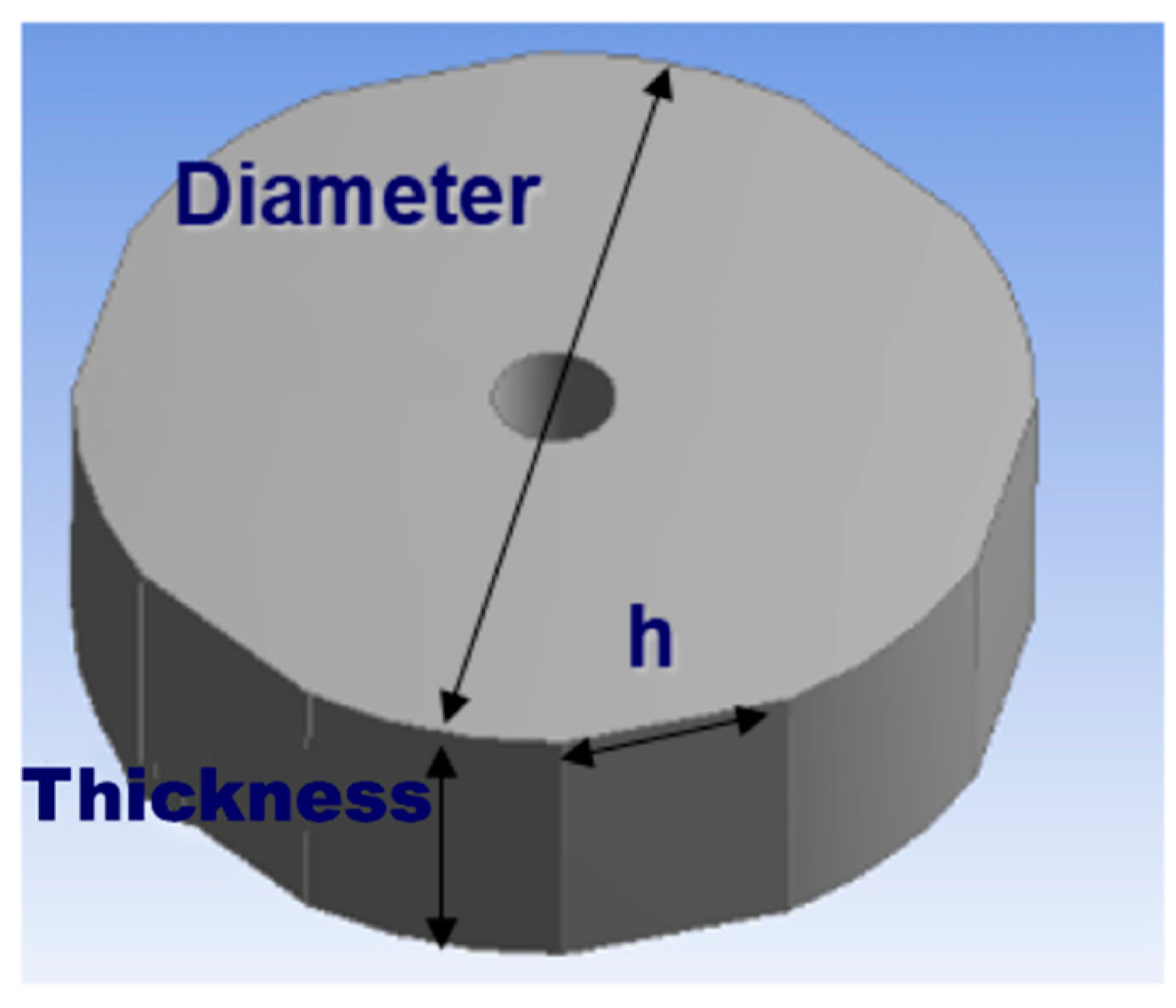
The shape and dimensions of the die were set, as shown in Figure 3; the thickness was 50 mm, the outer diameter was 160 mm, the inner diameter was 20 mm, and the flattening curve was 40 mm for use at 19.8 kHz.
The ultrasonic compaction variables are displayed in Table 1. The material used for this research was limited to SMCs termed SMC550 and SMC500. The coefficient of the relation equation of determining density of SMCs was firstly taken. Table 2 shows the coefficient of the equation for determining the density of SMCs without ultrasonic action. Through Table 1 and Table 2, the resultant density with ultrasonic action may consist of two portions, as shown in Equations (1) and (2); one is the density increase by the ultrasonic effect and the other is the conventional compaction effect, without the ultrasonic effect.
![Materials 12 00824 i001]()

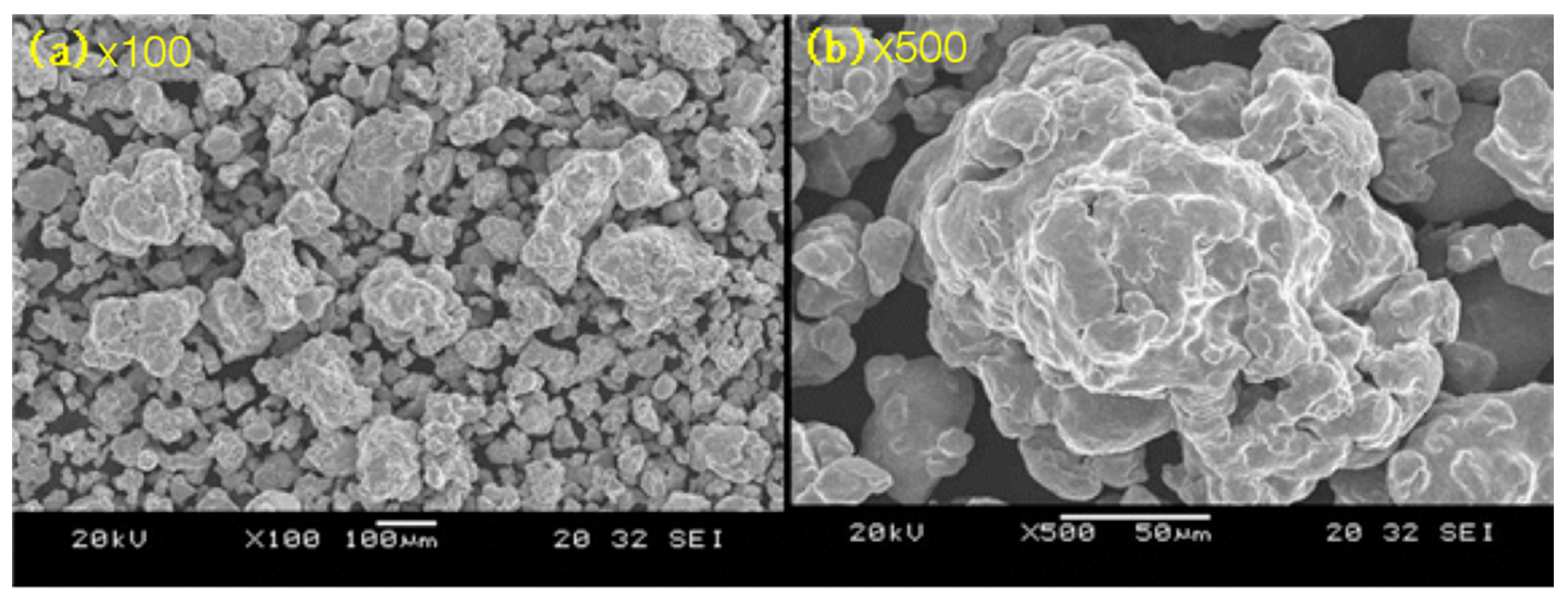
To observe the voids or porosity among the particles, a microscopic analysis of the SMC powders was needed. In Figure 4, the SEM (Scanning Electron Microscope) pictures of SMC500 are shown, which were used for the analysis.
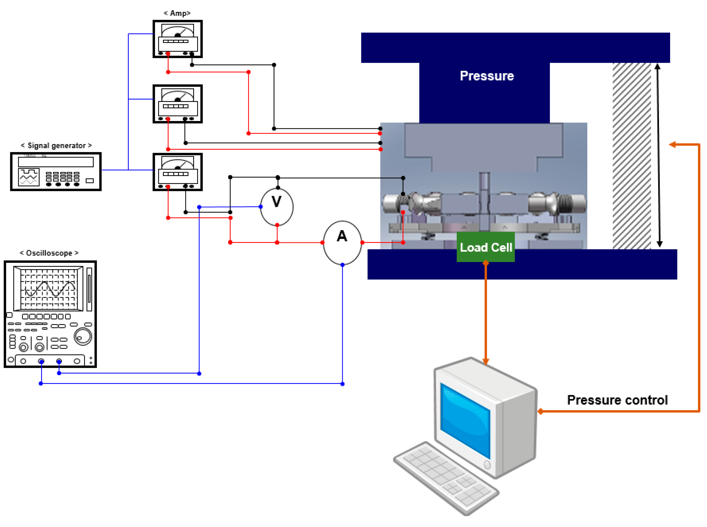
The equipment installed and its setup for the experiment are shown in Figure 5, and were also published in our previous work [16]. In this research, a Universal Test Machine (UH-F500) (Shimadzu, Kyoto, Japan) was used to apply the pressure. The ultrasonic wave was produced by a signal generator (WF1943A) (NF corporation, Yokohama, Japan) and enlarged through a high-power amplifier (HSA4101) (NF corporation, Yokohama, Japan). The amplified wave was applied to each vibrator. The input current and voltage were measured by CT (Current Transformer) and PT (Potential Transformer) at the point where the ultrasonic transducer was connected and the values were displayed using an oscilloscope. Each amplifier generated a maximum voltage of 200 V and a maximum current of 1A. Also, in order to consider the effect of the driving frequency on the densification of SMCs, the change in density with different driving frequencies was measured. Here, vibration compacting die was designed for operating at 20 kHz half wavelength longitudinal vibration and the press frame had a hydraulic static compacting pressure source. The experiment was conducted for 3 seconds, so as not to destroy the insulation layer due to the temperature increase.
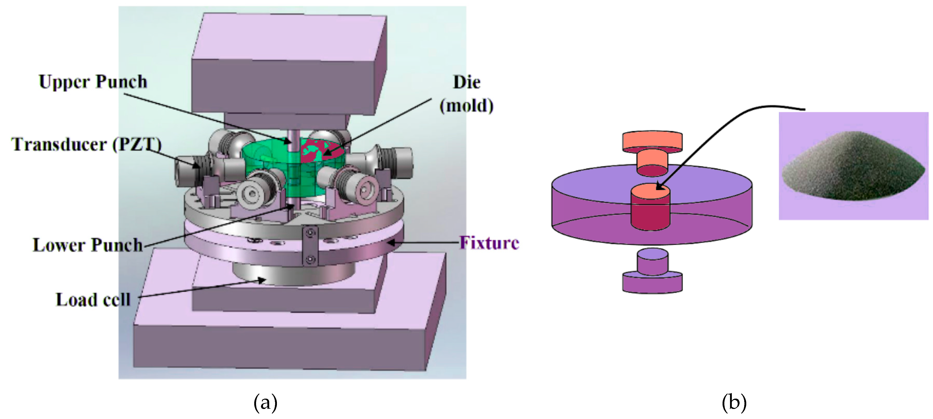
The ultrasonic compaction system was set up as shown in Figure 6. A soft magnetic composite (SMC) was chosen among various types of powder. The SMC has a very high potential for practical use due to its outstanding magnetic characteristics, but its compact density cannot increase beyond a certain level. Hence, its mechanical strength is limited up to a certain point using a conventional compaction method. If the mechanical strength of the SMC could be improved through an ultrasonic compaction process, then more advanced materials that are made of SMCs could be produced. For this reason, the SMC was chosen to be tested among other powders.
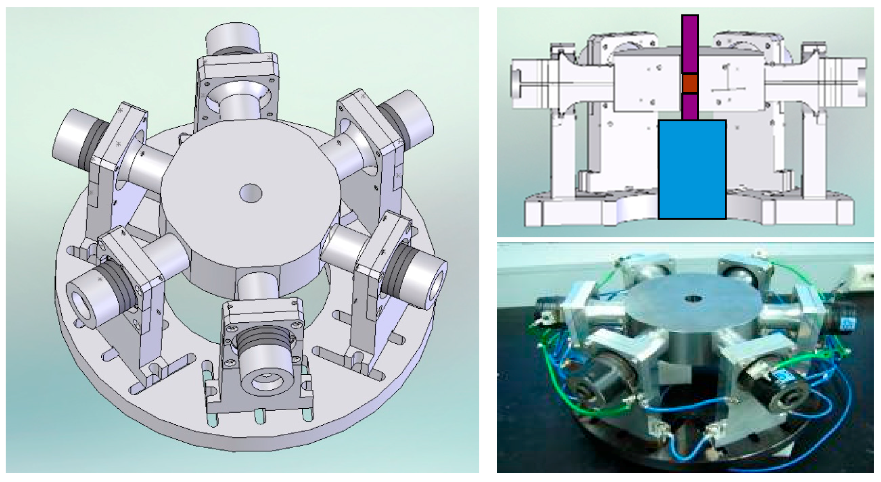
Figure 7 shows the assembled ultrasonic compaction mold system with the supporting fixture. A total of six ultrasonic transducers were connected to the die and arranged in a radial direction. From the cross-sectional view (upper right picture in Figure 7), there was a hole where the specimen was compacted and structured. In the lower right picture of Figure 7, the connection method between the ultrasonic transducer and the fixture was also described. In order to prevent the production of an electrical shock, the ground line (green cable) was set up at the die and fixture opposite each other.
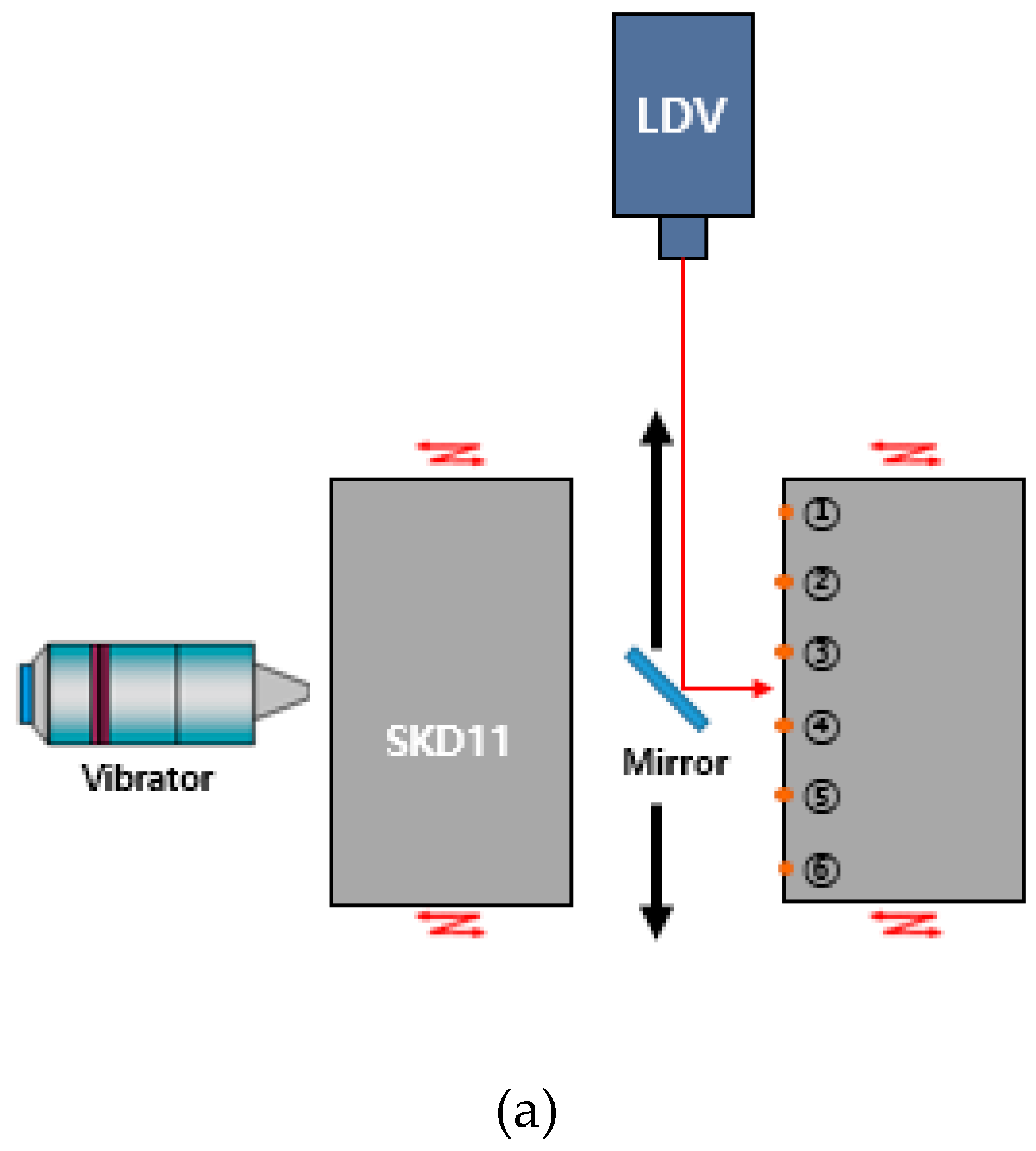
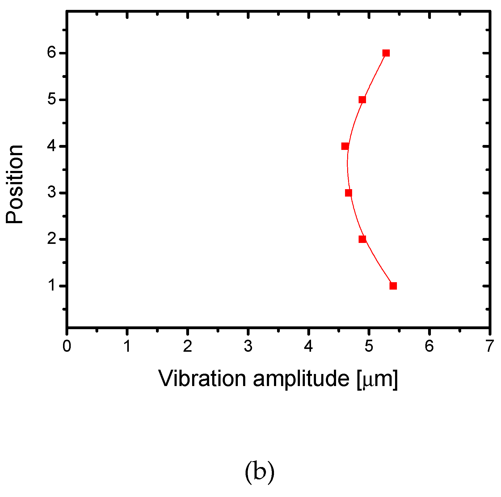
Figure 8 shows the measured results of the vibration distribution of the interior area of a hole where the SMC was compacted. It was measured using a mirror because there was no margin in the interior area of the hole. The measured vibration amplitude distribution agreed well with the FEM (Finite Element Method) simulation results. The maximum vibration points were ① and ⑥, and the minimum vibration points were ③ and ④. However, the deviation of the vibration amplitude between the maximum and minimum points was almost the same at each point with a deviation of 1.5 μm. The vibration amplitude of position No.1 was 5.5 μm.
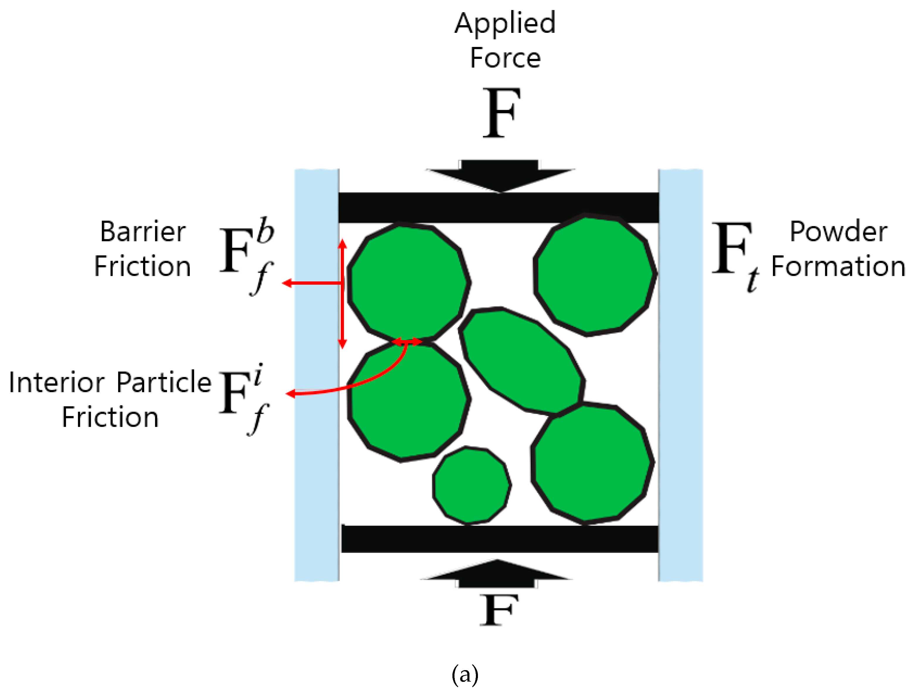
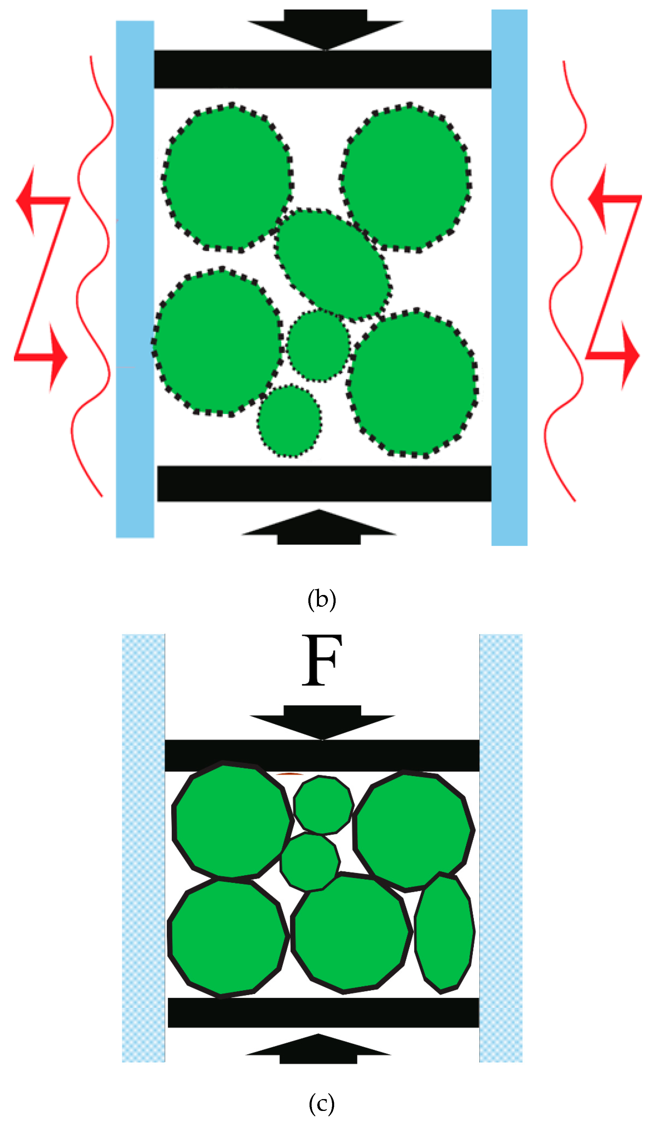
As the ultrasonic compaction is taking place, the proposed system is expected to undergo densification, as described below. In the first stage, pressure is applied to the SMC sample in the die where the density is determined by the equilibrium force, as expressed in Equation (3). The applied force contributes to the densification of the SMC as shown in Figure 9a.
The friction between the die wall and powders as well as between the particles themselves prevent the further densification of the SMC. Densification is also affected by the formation force. Therefore, the resultant density is achieved when the applied and resistance force reach an equilibrium state.
where : Applied force; : Barrier friction force; : Inter-particle friction; : Formation force. : Friction coefficient between barrier and powder; : Friction coefficient among particles themselves;
In the second stage, the ultrasonic vibration is applied to the die through BLT (Bolt Clamped Langevin Type) -type ultrasonic transducers while the pressure is applied, as shown in the Figure 9b. Ultrasonic vibration is an effective way to reduce the internal friction [11], because it has a small amplitude and high frequency. Vibration of the die wall, therefore, is expected to reduce the internal friction between the die wall and particles, as well as the inter-particle friction in a system. The SMC powder then rearranges itself to go into empty spots due to the lowered internal friction, and the further densification of SMC is achieved as shown in Figure 9c.
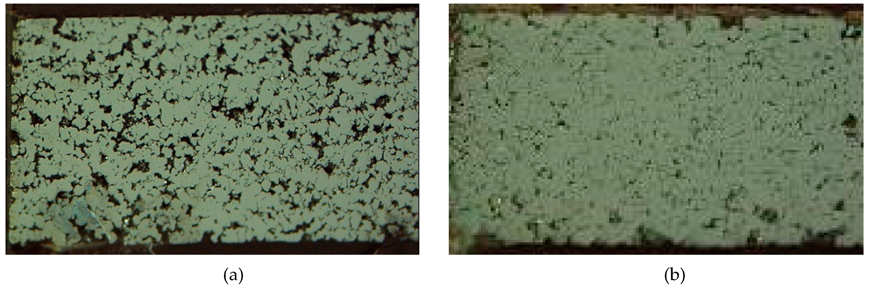
To observe the voids or porosity among the particles after compaction, a microscopic analysis was carried out. In Figure 10, the microstructures of compacts with and without ultrasonic vibration are shown with a compressive pressure of 300 Mpa. Because of the low pressure applied, the experiment was in the “repacking” stage. As shown, there was higher porosity exhibited after the conventional compaction method than after ultrasonic vibration. Even with the same compressive pressure, the density increment by the reduction of porosity between the particles was clearly observed in the microstructure.
3. Analysis of Densification Mechanism under Ultrasonic Compaction
3.1. Conventional Compaction Mechanism
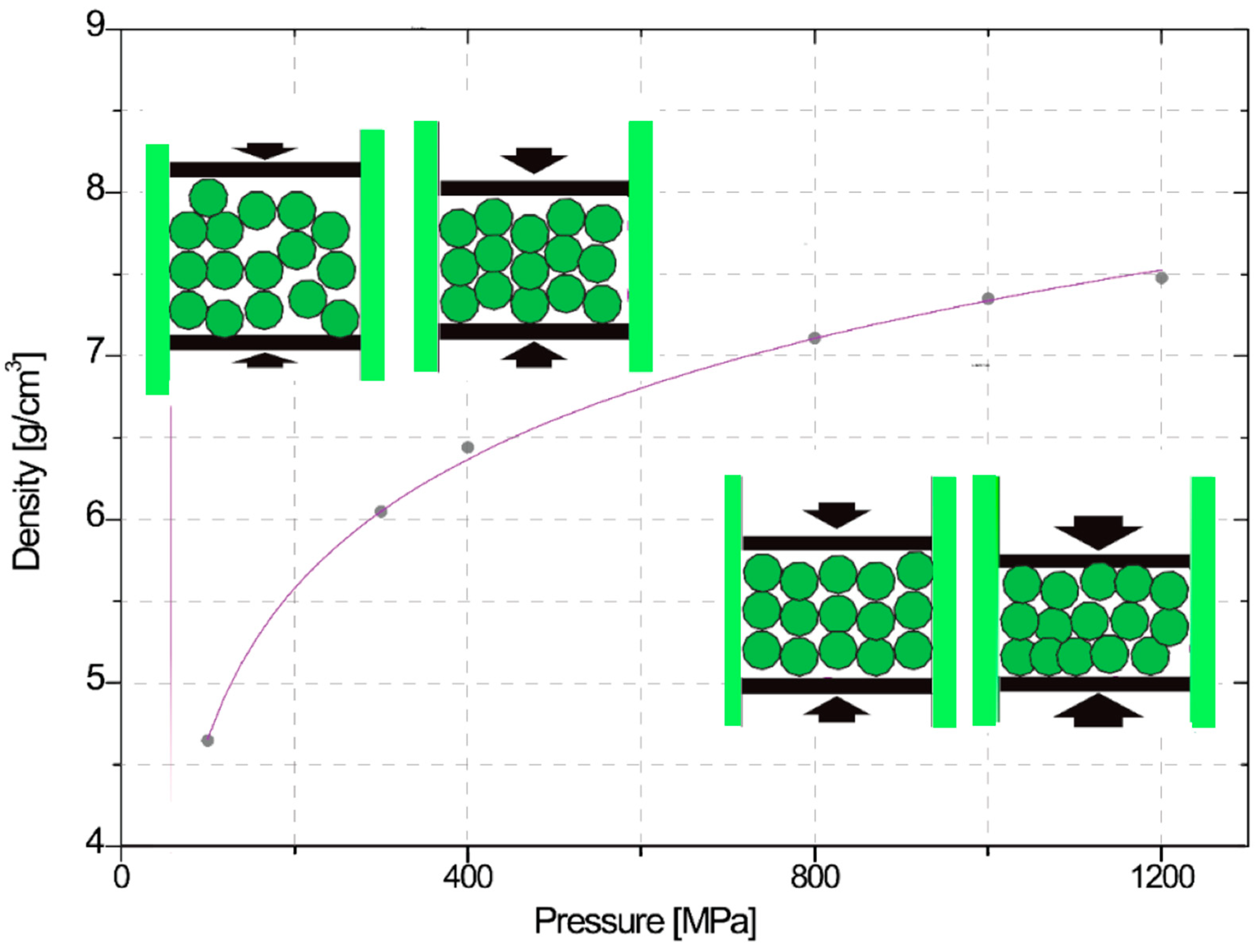
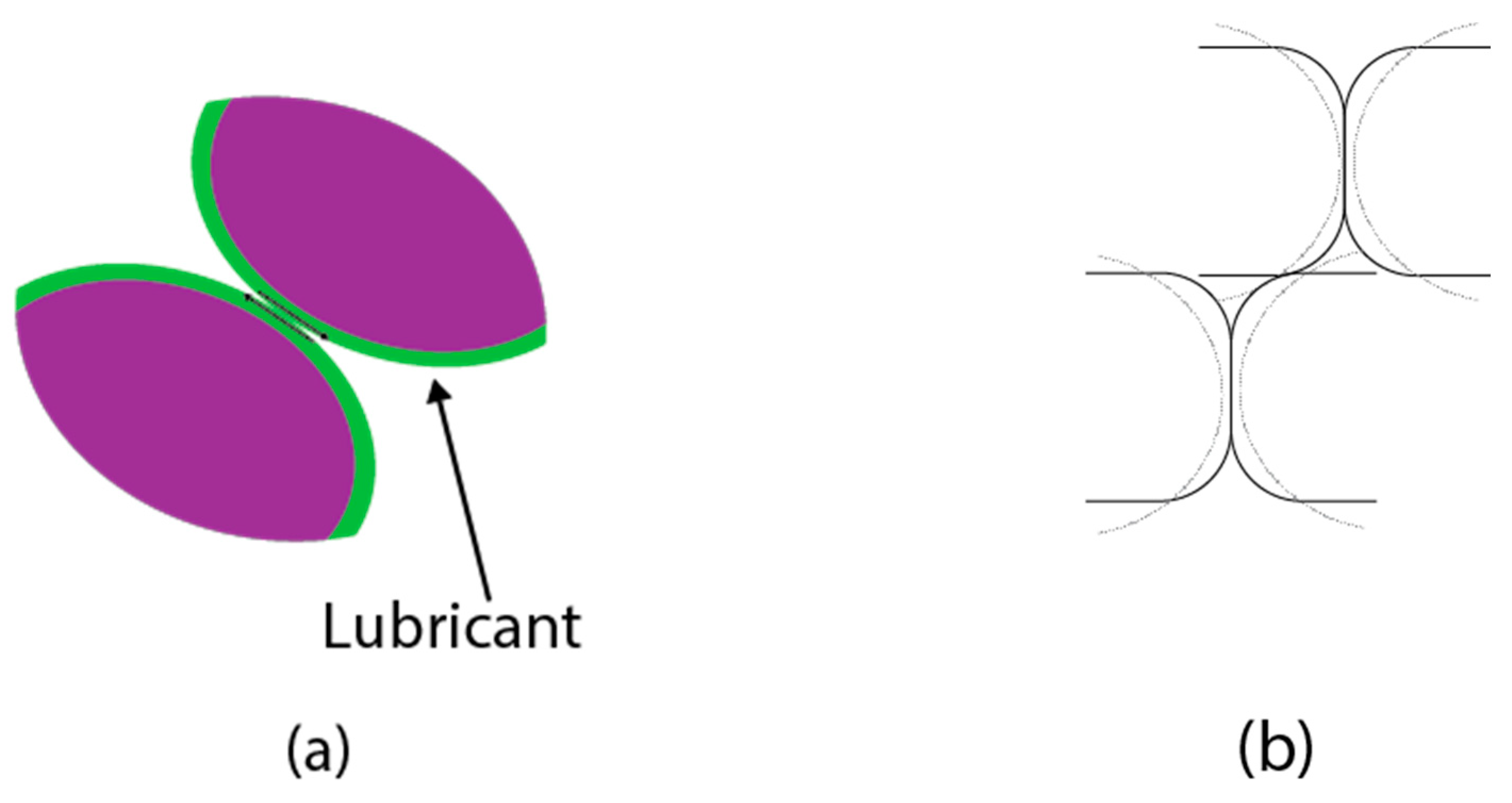
The material used for this experiment was SMC500, and for the lubricant, Kenolube was used. This is a type of organic lubricant and a proprietary lubricant, containing 2% Zn. Kenolube is sensitive to high temperatures and mostly high ambient humidity, which promotes the formation of lumps and negatively impacts the flow behavior. A general mechanism of conventional compaction is shown in Figure 11. During the first step of compaction, particles slip among themselves under pressure, and rearrange their positions without the deformation of the powder. This step is called ‘repacking’ in which the density is raised. In the second step, particles from the powder start to deform at high pressures of over 400 MPa, and this step in which the density increases is called ‘deformation’ [15]. As shown in Figure 11, there is no clear distinction between the repacking and the deformation steps. However, repacking generally occurs at a low pressure and deformation occurs at a high pressure. The dominant contributing factor raising the densification is illustrated in Figure 8, showing slipping and rearrangement between the particles in the repacking step and the deformation step under high pressure [17,18]. In Figure 12a, the blue outline indicates the lubricant.
3.2. Density Comparison with Ultrasonic and Non-Ultrasonic Effects under Different Compacting Pressures
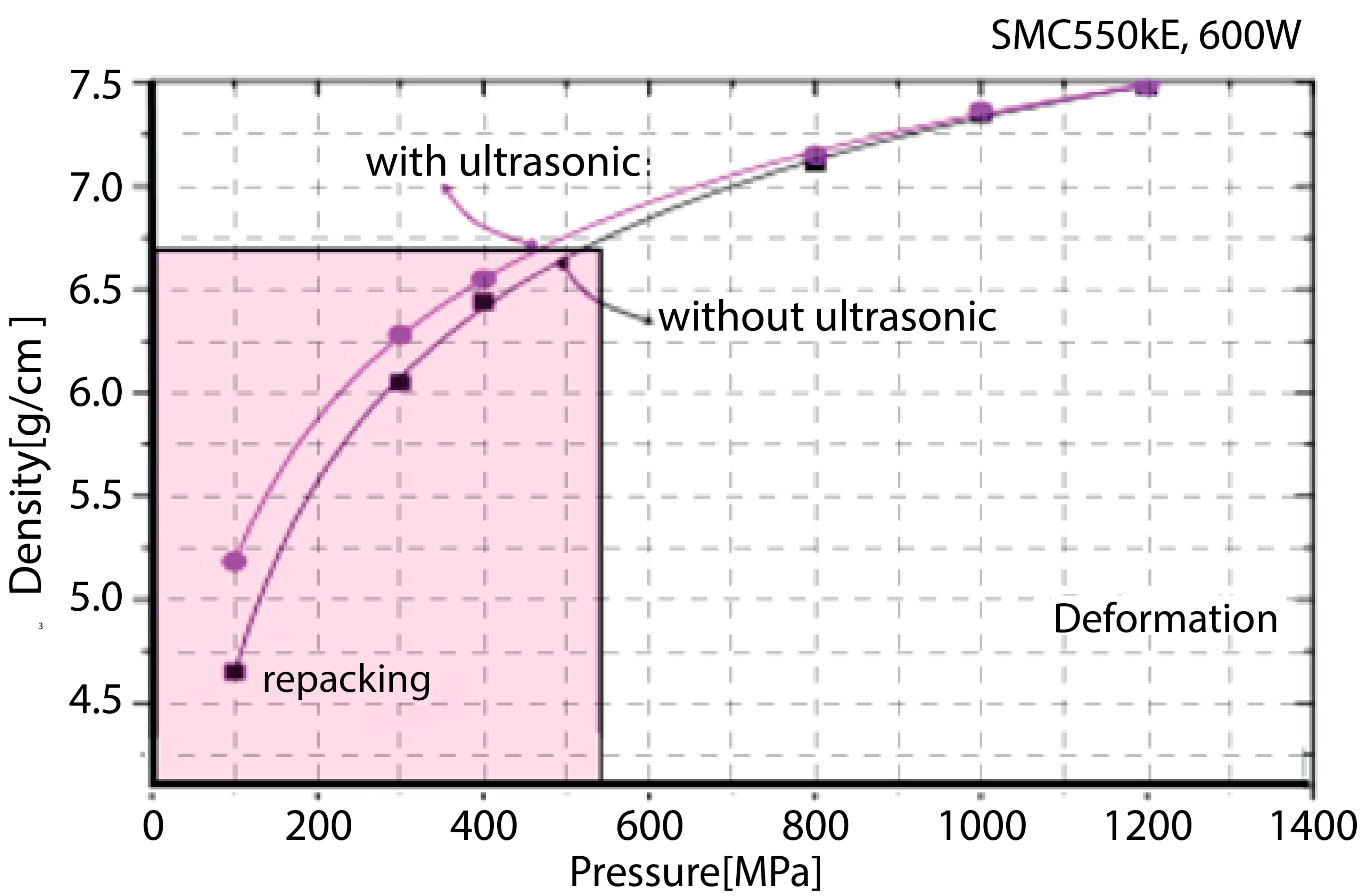
The density of the SMC test sample was measured under various pressure conditions from 100 to 1200 MPa. Figure 13 shows the density profile of the SMC sample when it was compacted with and without ultrasonic vibration during the compaction process. The SMC specimen with ultrasonic vibration showed a higher density profile than that of the SMC specimen without ultrasonic vibration. By comparing the densities between two such cases, the difference in density was larger in the repacking region than in the deformation region. From this experiment, it can be inferred that ultrasonic vibration during the compaction process mostly contributes to the slipping and rearrangement of the particles, since repacking dominantly occurs in the low-pressure range, as discussed in Section 3.1.
3.3. Analysis of Repacking Effect on the SMC Density
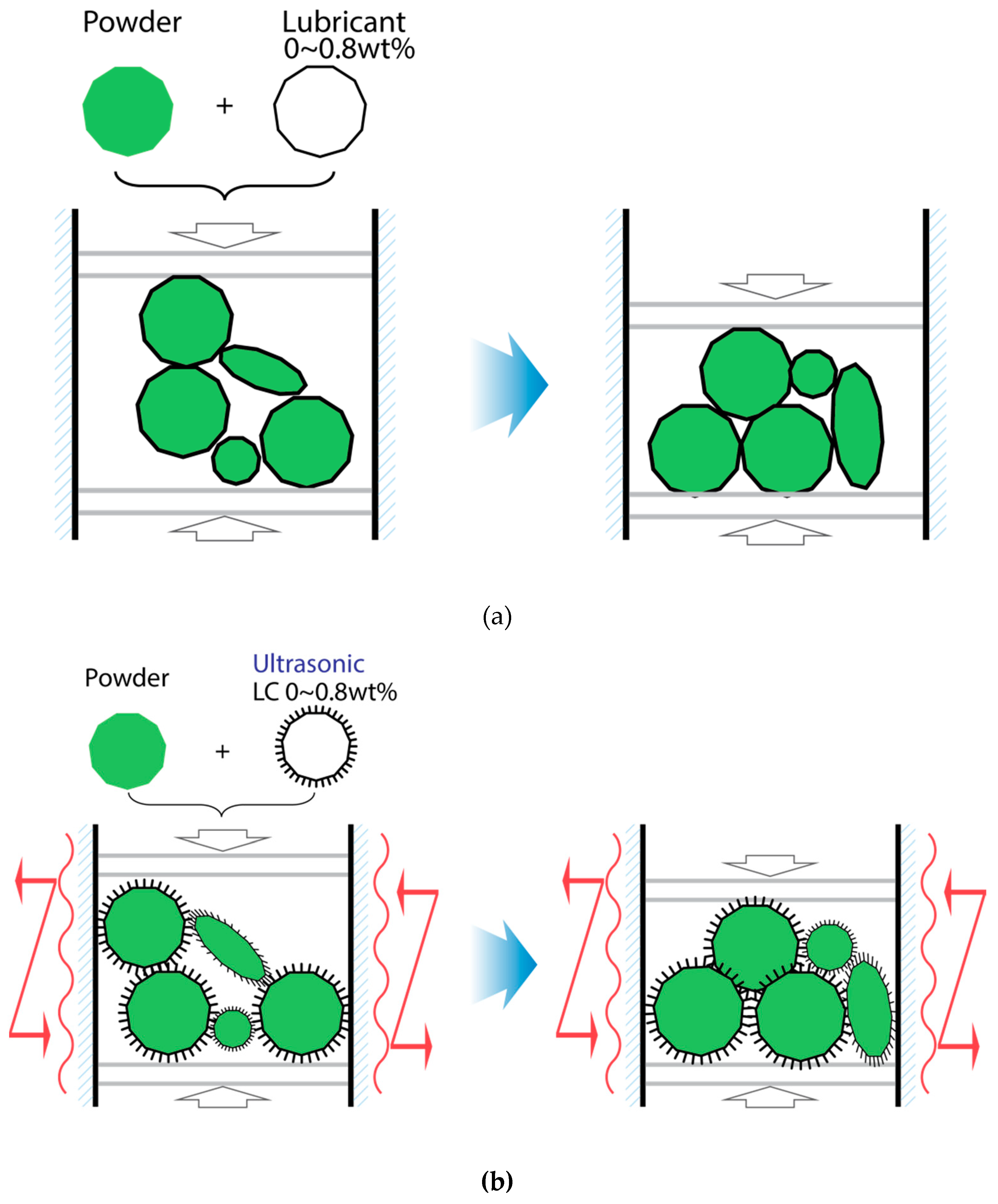
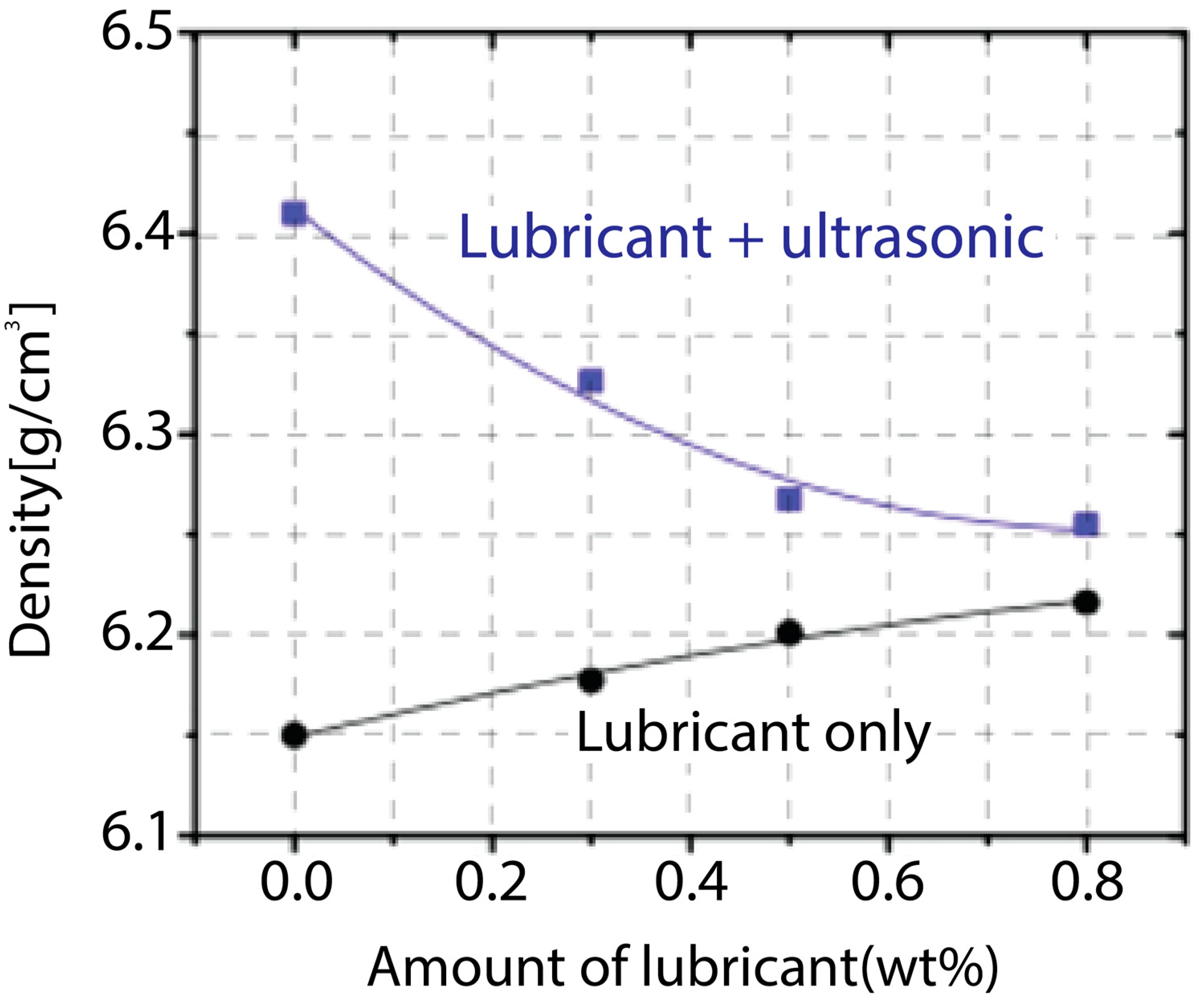
In order to verify the density improvement caused by the repacking step described in the previous section, powder and lubricant mixtures with a mixing ratio from 0 to 0.8 wt% lubricant were made. Lubricant is used in this experiment because it enhances the slipping of the powders during the compaction process. To compare the results from a lubricant experiment, an ultrasonic vibration, which was experimentally shown to enhance the slipping and rearrangement of particles in Figure 13, was applied to each SMC test sample. The experimental concept, which is based on a force balance model, is shown in Figure 14. Figure 14a depicts the conventional powder compaction procedures only with lubrication whereas Figure 14b shows the densification procedures with a combination of ultrasonic compaction and lubrication. At a constant pressure of 300 MPa, the density of the compacted powder was measured in both cases. The amounts of lubricant used varied from 0.0 to 0.8 wt% and the results are shown in Figure 15.
The experimental result of the density with ultrasonic vibration is exhibited in Figure 15. As shown, when ultrasonic vibration was applied, the effect on the slipping of the powders and consequent result in the increase of density was very significant, even when the powder was not lubricated. The density of the SMC and lubricant mixture without ultrasonic effects is plotted as a black curve, and the density of the SMC and lubricant mixture with ultrasonic effects is shown as a blue curve. It is interesting to note that both black and blue curves tend to reach around the same value as an increase in lubricant was added. The lubricant plays a role in decreasing internal friction in the compaction process, as discussed in previous sections. Since both curves reach around the same value, it is experimentally proven that ultrasonic effects also play the same role as the lubricant in the compaction process, which is to decrease frictional forces.
Although both curves direct towards the same level, the blue and black curves behave differently. The black curve increases as more lubricant is added because the SMC sample can rearrange and go easily into to the empty spots in the system due to the lowered frictional forces among the particles themselves. This rearrangement of the SMC sample eventually increases the densification of tested particles because many empty spots can be filled up with rearranged SMC particles, and thus the sample can become more compacted. As more lubricant was added, the blue line showed a downtrend. Even though the internal friction decreased as more lubricant was added, the thickness of the lubricant coating around the SMC sample increased significantly, thus cancelling out the slipping and rearrangement effects. The rearrangement of the SMC sample is not as easy as in the previous case because fewer SMC particles can go into empty spots due to their thick lubricant coating. Thickening the coating around the particles was a more dominant factor in this case, thus the blue curve decreased as more lubricant was added. In the end, the density increased about 5~10% with a high-power ultrasonic compaction system compared that of the conventional compaction system.
4. Conclusions
There have been many cases reported in academic societies indicating that ultrasonic compaction contributes to a higher densification of given samples. Ultrasonic compaction technology has received great attention recently since the low mechanical strength of given samples can be improved when it is used to develop the motor core. It is important to note, however, that the reasoning for this phenomenon and the densification mechanism of an ultrasonic compaction has not been reported yet. Due to this unknown mechanism, quantitative analysis of ultrasonic compaction could be done with limitations.
Based on the proposed force balance model, the experiments were designed to test and measure the densification of SMC samples with both ultrasonic and non-ultrasonic effects in the compaction process. The density profile of the SMC sample with an ultrasonic effect was higher than that with the non-ultrasonic effect. Ultrasonic compaction lowered the internal friction between particles and the die wall, as well as the inter-particle friction inside the die wall. Thanks to this lowered internal friction, particles can rearrange and go into empty spots, making a more compacted SMC sample. In order to verify this high densification phenomenon, the mixture of SMC and lubricant was made with different mixing ratios. As more lubricant was added to the SMC sample with the non-ultrasonic compaction effect, a higher densification was achieved due to the lowered internal friction among the particles themselves. Thus, it was experimentally proved that the ultrasonic compaction effect plays the same role as a lubricant in the compaction process—lowering the internal friction in the system.
With the densification mechanism studied in this paper, a motor made of an SMC core, which was fabricated using an ultrasonic compaction, showed an enhanced efficiency by up to 5% compared to that of a motor made via a conventional method [19,20]. With the proposed mechanism, various applications and modified technologies, such as the example given above, can be achieved and the successful industrialization of ultrasonic compaction in various sectors is expected.
Author Contributions
Conceptualization, M.-H.H. and H.-R.C.; Data curation, H.-S.L.; Formal analysis, H.-S.L.; Methodology, S.Y.J.; Supervision, H.-R.C.; Validation, D.-H.K. and J.-H.H.; Visualization, M.-H.H.; Writing—original draft, M.-H.H.; Writing—review & editing, H.-R.C.
Funding
This research was funded by the support of the Korea Institute of Industrial Technology as “Variable Architecture Powertrain Platform and Self-Driving Factor Technology Development for Industrial EV Self-Driving Vehicle” (KITECH EO-19-0038).
Conflicts of Interest
The authors declare no conflict of interest.
References
- Polinder, H.; Hoeijmakers, M.J. Eddy-current losses in the segmented surface-mounted magnets of a PM machine. IEE Proc.-Electr. Power Appl. 1999, 146, 261–266. [Google Scholar] [CrossRef]
- Shokrollahi, H.; Janghorban, K. Soft magnetic composite materials (SMCs). J. Mater. Process. Technol. 2007, 189, 1–12. [Google Scholar] [CrossRef]
- Guo, Y. Measurement and modeling of core losses of soft magnetic composites under 3-D magnetic excitations in rotating motors. IEEE Trans. Magn. 2005, 41, 3925–3927. [Google Scholar]
- Guo, Y. Development of a PM transverse flux motor with soft magnetic composite cores. IEEE Trans. Energy Convers. 2006, 21, 426–434. [Google Scholar] [CrossRef]
- Kondoh, M.; Takashi, S.; Hiroyuki, T. Green Compact and Process for Compacting the Same, Metallic Sintered Body and Process for Producing the Same, Worked Component Part and Method of Working. U.S. Patent Application No. 10/615,939, 22 January 2004. [Google Scholar]
- Li, Y.Y. Effect of die wall lubrication on warm compaction powder metallurgy. J. Mater. Process. Technol. 2002, 129, 354–358. [Google Scholar] [CrossRef]
- Hasegawa, T.; Koyama, D.; Nakamura, K.; Ueha, S. Modeling and performance evaluation of an ultrasonic suction pump. JJAP 2008, 47, 4248–4252. [Google Scholar] [CrossRef]
- Kumar, V.C.; Hutchings, I.M. Reduction of the sliding friction of metals by the application of longitudinal or transverse ultrasonic vibration. Tribol. Int. 2004, 37, 833–840. [Google Scholar] [CrossRef]
- Pohlman, R.; Lehfeldt, E. Influence of ultrasonic vibration on metallic friction. Ultrasonics 1966, 4, 178–185. [Google Scholar] [CrossRef]
- Tsujino, J.; Suzuki, H. Ultrasonic vibration press of powder using 20 kHz upper and lower vibration punches and a vacuum compacting die. Jpn. J. Appl. Phys. 1992, 31, 290–293. [Google Scholar] [CrossRef]
- Tsujino, J.; Ueoka, T.; Aoyama, T.; Karatsu, R.; Kyuzen, T. 27 kHz Ultrasonic Complex Vibration Source Using (1, 1) Mode Transverse Vibration Disk with Multiple Transducers of 40 mm Diameter. JJAP 2007, 46, 4945–4947. [Google Scholar] [CrossRef]
- Khasanov, O.L.; Dvilis, E.S.; Sokolov, V.M.; Pokholkov, Y.P. Investigation of structural hierarchy of nanoceramics compacted by dry pressing under powerful ultrasound action. Key Eng. Mater. 2004, 268, 73–76. [Google Scholar] [CrossRef]
- Khasanov, O.L.; Edgar, S.D. Net shaping nanopowders with powerful ultrasonic action and methods of density distribution control. Adv. Appl. Ceram. 2008, 107, 135–141. [Google Scholar] [CrossRef]
- Khasanov, O.L. Effect of ultrasonic compaction of nanopowder on structure and fracture character of zirconia nanoceramics. In Fracture Mechanics of Ceramics; Springer: Boston, MA, USA, 2002; pp. 503–512. [Google Scholar]
- German, R.M. Powder Metallurgy & particulate materials processing. In Metal Powder Industries Federation; Metal Powder Industry: Princeton, NJ, USA, 2005; ISBN 0-9762057-1-8. [Google Scholar]
- Cha, H.R.; Lee, S.H.; Jeon, S.K.; Cho, J.I.; Kikuch, S.; Nakamura, K. Motor Core Fabrication through Ultrasonic Vibration Compaction of Soft Magnetic Composite. JJAP 2009, 48, 07GM18-1–07GM18-7. [Google Scholar] [CrossRef]
- York, P. Particle slippage and rearrangement during compression of pharmaceutical powders. J. Pharm. Pharmacol. 1978, 30, 6–10. [Google Scholar] [CrossRef] [PubMed]
- Mallick, S. Study of particle rearrangement, compression behavior and dissolution properties after melt dispersion of ibuprofen, Avicel and Aerosil. Results Pharma Sci. 2011, 1, 1–10. [Google Scholar] [CrossRef] [PubMed] [Green Version]
- Guo, Y.; Zhu, J.; Dorrell, D.G. Design and analysis of a claw pole permanent magnet motor with molded soft magnetic composite core. IEEE Trans. Magn. 2009, 45, 4582–4585. [Google Scholar]
- Morimoto, M. Performance improvement of induction motor made of three dimensional shaped SMC core. In Proceedings of the 2011 IEEE Ninth International Conference on Power Electronics and Drive Systems (PEDS), Singapore, 5–8 December 2011. [Google Scholar]
Figure 1.
The occurring mechanism of the eddy current loss.

Figure 2.
Heat applied during sintering causes defects in the insulation layer.

Figure 3.
Design parameter for ultrasonic compaction.

Figure 4.
Optical microscope observations of SMC500.

Figure 5.
Full configuration of experiment.

Figure 6.
Ultrasonic vibration compaction system: (a) compaction system diagram, (b) illustration of basic operation concept.
Figure 6.
Ultrasonic vibration compaction system: (a) compaction system diagram, (b) illustration of basic operation concept.

Figure 7.
Assembled ultrasonic compaction mold system with supporting fixture.

Figure 8.
Vibration distribution of the hole where the SMC is compacted: (a) measurement setup; (b) vibration distribution according to six positions.
Figure 8.
Vibration distribution of the hole where the SMC is compacted: (a) measurement setup; (b) vibration distribution according to six positions.


Figure 9.
Procedure of ultrasonic compaction: (a) stage 1—only pressure; (b) stage 2—pressure + ultrasonic, (c) final stage (after densification).
Figure 9.
Procedure of ultrasonic compaction: (a) stage 1—only pressure; (b) stage 2—pressure + ultrasonic, (c) final stage (after densification).


Figure 10.
Optical microscope observation of compacted material with and without ultrasonic vibration: (a) conventional compaction; (b) ultrasonic compaction.
Figure 10.
Optical microscope observation of compacted material with and without ultrasonic vibration: (a) conventional compaction; (b) ultrasonic compaction.

Figure 11.
Conventional densification mechanisms under various pressure conditions.

Figure 12.
The contributing factors raising the densification: (a) slipping between particles during the repacking step; (b) deformation of the particles.
Figure 12.
The contributing factors raising the densification: (a) slipping between particles during the repacking step; (b) deformation of the particles.

Figure 13.
Ultrasonic vibration effect on density during compaction under different pressure conditions.
Figure 13.
Ultrasonic vibration effect on density during compaction under different pressure conditions.

Figure 14.
Illustration of the repacking mechanism with different amounts of lubricant usage: (a) compaction with lubricant usage only; (b) compaction with both lubricant and ultrasonic usage.
Figure 14.
Illustration of the repacking mechanism with different amounts of lubricant usage: (a) compaction with lubricant usage only; (b) compaction with both lubricant and ultrasonic usage.

Figure 15.
Density comparison between ultrasonic and non-ultrasonic effects under different lubrication conditions.
Figure 15.
Density comparison between ultrasonic and non-ultrasonic effects under different lubrication conditions.


Table 1.
Variables for ultrasonic compaction.
| Parameter | Function | Parameter | Function |
|---|---|---|---|
| u | Vibration amplitude (~20 μm) | po | Compacted position |
| F | Force | mo | Modal shape |
| A | Ultrasonic applied area | St | Strength of material |
| P | Pressure | Si | Size of material |
| t | Operating time (~3 s) | lu | Effect of lubricant |
| f | Frequency (15, 20, 38 Khz) | Sh | Shape of material |
| fr | Friction |
Table 2.
Coefficient of the relation equation of determining the density of the soft magnetic composites (SMCs).
Table 2.
Coefficient of the relation equation of determining the density of the soft magnetic composites (SMCs).
| a | b | c | |
|---|---|---|---|
| SMC550KE * | 1.933 | 0.106 | 0.894 |
| SMC550 * | −4.830 | 0.084 | 1.819 |
| SMC500KE * | 3.283 | 0.125 | 0.364 |
| SMC500 * | 1.266 | 0.118 | 0.682 |
* Trademark of Hoganas, Sweden.
© 2019 by the authors. Licensee MDPI, Basel, Switzerland. This article is an open access article distributed under the terms and conditions of the Creative Commons Attribution (CC BY) license (http://creativecommons.org/licenses/by/4.0/).
Share and Cite
MDPI and ACS Style
Hwang, M.-H.; Lee, H.-S.; Han, J.-H.; Kim, D.-H.; Cha, H.-R. Densification Mechanism of Soft Magnetic Composites Using Ultrasonic Compaction for Motors in EV Platforms. Materials 2019, 12, 824. https://doi.org/10.3390/ma12050824
AMA Style
Hwang M-H, Lee H-S, Han J-H, Kim D-H, Cha H-R. Densification Mechanism of Soft Magnetic Composites Using Ultrasonic Compaction for Motors in EV Platforms. Materials. 2019; 12(5):824. https://doi.org/10.3390/ma12050824
Chicago/Turabian StyleHwang, Myeong-Hwan, Hae-Sol Lee, Jong-Ho Han, Dong-Hyun Kim, and Hyun-Rok Cha. 2019. "Densification Mechanism of Soft Magnetic Composites Using Ultrasonic Compaction for Motors in EV Platforms" Materials 12, no. 5: 824. https://doi.org/10.3390/ma12050824
Note that from the first issue of 2016, this journal uses article numbers instead of page numbers. See further details here.