A Novel, Multifunctional, Floatable, Lightweight Cement Composite: Development and Properties
by
Zhenyu Huang
1,*, 
Fang Wang
1,
Yingwu Zhou
1,
Lili Sui
1,*,
Padmaja Krishnan
2 and
Jat-Yuen. Richard Liew
2 1
Guangdong Provincial Key Laboratory of Durability of Marine Civil Engineering, Shenzhen University, Shenzhen 518060, China
2
Department of Civil and Environmental Engineering, National University of Singapore, Singapore 117576, Singapore
*
Authors to whom correspondence should be addressed.
Materials 2018, 11(10), 2043; https://doi.org/10.3390/ma11102043
Submission received: 5 October 2018
/
Revised: 16 October 2018
/
Accepted: 18 October 2018
/
Published: 19 October 2018
(This article belongs to the Section Advanced Composites)
Abstract
:This paper presents the development of a novel, multifunctional, floatable, lightweight cement composite (FLCC) using three different types of glass microspheres for structural engineering applications. Eight different mixtures of FLCC were produced and their matrix-related parameters were examined experimentally by adopting different types of microsphere fillers, fiber content (polyethylene fibers (PE)), and water-to-binder ratios. Along with the mechanical properties such as compressive, flexural, tensile strengths, and modulus of elasticity, the water tightness of the material was evaluated by sorptivity measurements and the energy efficiency by thermal conductivity. The optimal FLCC has an oven-dry density of 750 kg/m3, compressive strength (fcm) up to 41 MPa after 28-day moist curing, low thermal conductivity of 0.152 W/mK, and very low sorptivity. It is found that an optimized amount of PE fiber is beneficial for improving the tensile resistance and ductility of FLCC while a relatively large amount of microspheres can increase the entrapped air voids in the FLCC matrix and reduce its density and thermal conductivity. Microstructural analysis by scanning electron microscopy (SEM) reveals that the microspheres are distributed uniformly in the cement matrix and are subjected to triaxial compression confinement, which leads to high strength of FLCC. Segregation due to density difference of FLCC ingredients is not observed with up to 60% (by weight) of glass microspheres added. Compared to the other lightweight aggregate concretes, the proposed FLCC could be used to build floating concrete structures, insulating elements, or even load-bearing structural elements such as floor and wall panels in which self-weight is a main concern.
1. Introduction
In the past decade, the construction industry all over the world has been exploring solutions to improve the productivity in site construction. The focus was placed on the reduction of site manpower usage at reasonable cost while maintaining design variety and high-quality work. Concrete is one of the most widely used materials in construction. Nevertheless, lately the focus has shifted to sustainable development and various industries are striving to save energy and lower the environmental impact. Concrete is more frequently required to possess more advanced characteristics to achieve low density, low cost, better thermal insulation, superior mechanical properties, and eco-friendliness. As a result, a multifunctional, lightweight, high-strength concrete is a superior alternative material used for structural elements such as building floors, exterior wall panels, and roofing tiles in which self-weight needs to be reduced significantly. The main advantage of using lightweight concrete is the reduction of self-weight of structural members and overall structures, allowing smaller sizes of structural members and less reinforcing materials. Thus, requirements for foundations and transportation cost can be reduced significantly. Additionally, it allows for easy and rapid installation at construction sites due to its lower self-weight, thereby saving time and improving productivity in construction.
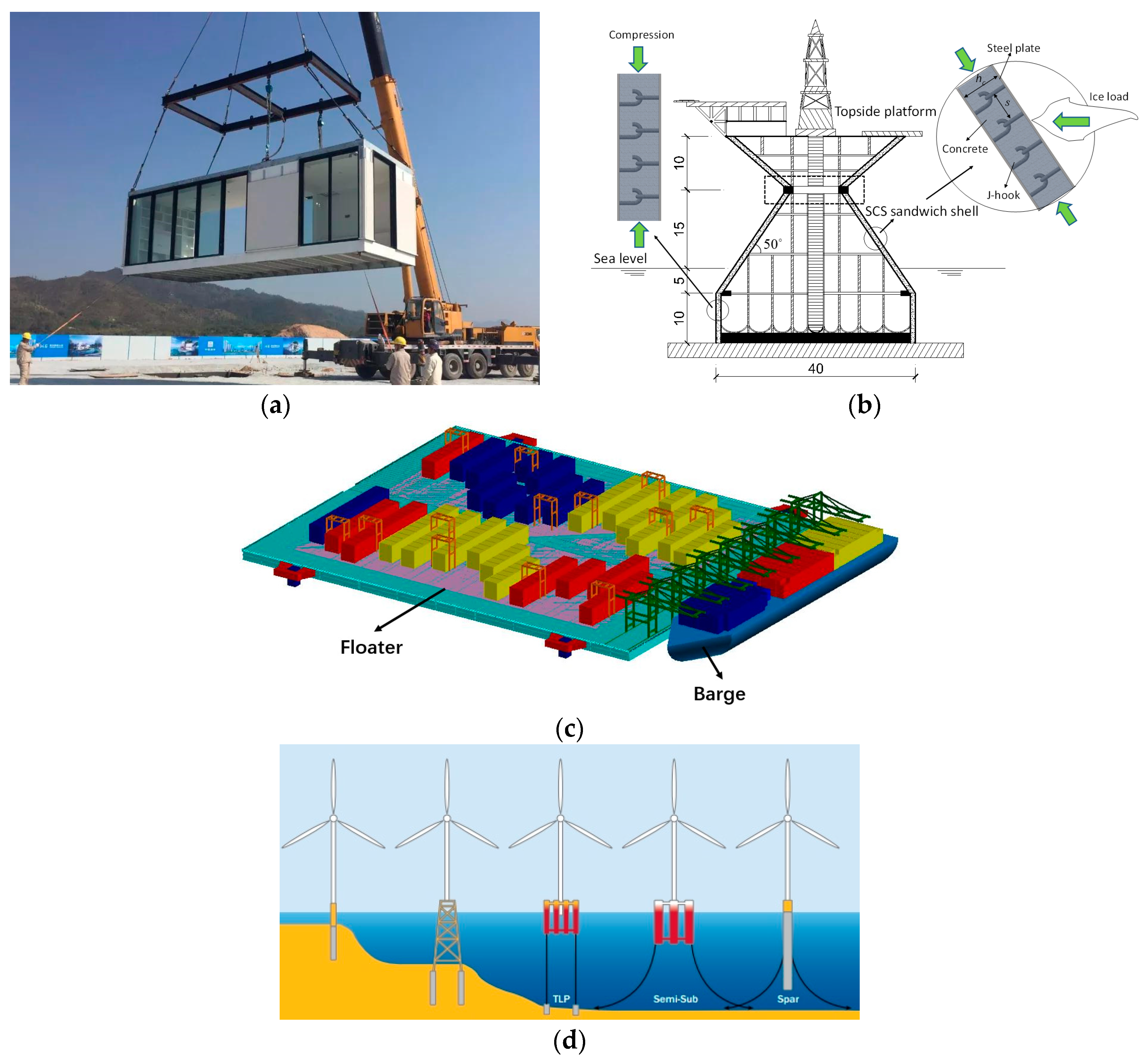
Lightweight onshore and offshore constructions shown in Figure 1a–d have become more and more promising in recent years. Lightweight concrete is attractive in structural components such as floor and wall panels, whose weight make up around 60% of the total self-weight of modular units [1,2]. Using lightweight concrete, the overall self-weight of the constructed structures could be much lighter than conventional concrete structures. For offshore floating structures, the platform is light enough to float and can be launched and ballasted so that it floats upright [3,4,5]. It will then be wet towed to the site for further assembly. It is essential that during the process of wet towing, the lightweight units are not compromised and their structural capacity is preserved.
Definitions of lightweight concrete vary among international standards and codes of practices. Table 1 lists the technical specifications of lightweight concrete for international codes, including CEB-FIP [6], ACI 213R [7], ASTM C330 [8], BS EN 13055 [9], and Chinese JGJ 51 [10]. In general, the unit weight of lightweight concrete ranges from 800 to 1950 kg/m3 while for structural lightweight concrete, ACI 213 recommends the range as 1120 to 1920 kg/m3 with compressive strength larger than 21MPa [7]. The methods for production of lightweight concrete can be mainly summarized as follows: (1) Adding lightweight aggregates into concrete mixtures, replacing completely or partially normal weight aggregates to achieve lightweight property. Conventional lightweight aggregates concrete incorporating expanded clay, expanded glass, expanded shale, expanded perlite, expanded vermiculite, foamed slag, expanded polystyrene beads, and fly ash aggregates has been developed and investigated in the past and has successfully achieved desired strength and unit weight for application [11,12,13,14,15,16]. (2) Adding foaming agent or air-entraining agent into the mixtures to introduce a certain volume of air voids in concrete mixtures [17,18]. However, this method could reduce the mechanical properties of concrete even though it could lower the density and increase the workability. (3) Gap grading of mixtures (sand is eliminated and voids are between coarse aggregate particles), for example, pervious concrete for pavement [19].
Extensive research has been done on the development of lightweight concrete. Lightweight concrete is generally weaker than normal concrete due to the brittleness and low modulus of lightweight aggregates, which to some extent restricts its wide application. Experimental investigations by Neville [20] showed that both mechanical properties and thermal conductivity of lightweight concrete show significant relation to density. There was a linear correlation between the thermal conductivity and the density of lightweight concrete (LWC) produced with different types of lightweight aggregates (LWAs), for example, pumice, vermiculite, cinders, expanded shale, and expanded slag. Chandra and Berntsson [21] presented a relationship between the compressive strength and density of LWC, applying expanded clay as LWA, for which the compressive strength of LWC increased from 7 to 16 MPa with density varied from 1000 to 1500 kg/m3. For structural application, Mydin et al. [22] and Prabha et al. [23] investigated the compression performance of a load-bearing wall system with lightweight foamed concrete infilled in double-skin profiled steel sheeting. However, the compressive strength of the foamed concrete was so low (around 6–8 MPa) that it had limited application in building construction (e.g., low-rise temporary housing). Additionally, particle characteristics of lightweight aggregates (LWAs) have great influence on the mechanical performance of the concrete [24]. To improve the ductility of LWC, fibers may be added to LWC [25]. Three types of fibers, metallic fibers, polymer fibers, and natural fibers, are utilized widely in concrete. While the density and thermal conductivity would be increased due to the higher density and thermal conductivity of metallic fibers, polymer fibers could be a good alternative to further improve both mechanical and functional properties without affecting the density and thermal conductivity.
Recent development on ultralightweight cement composite (ULCC) by Wu et al. [26], Huang et al. [27,28,29,30,31,32] showed that ULCC using fly ash cenospheres exhibited low density ranging from 1250 to 1550 kg/m3, high compressive strength up to 87.3 MPa, high flexural strength of 11.4 MPa, and deflection hardening behavior by using low steel fiber content (0.5% in volume) [33], which has been applied in steel–concrete–steel sandwich composite beams [27,30], walls [4,29,31], and shells [27,28,32] within marine offshore areas. As can be seen, use of lightweight fly ash cenospheres in cement-based composites has been an area of interest and a growing number of researchers investigate its mechanical and functional properties [33,34,35,36,37,38,39,40] and promote its application subjected to different loading scenarios [27,28,29,30,31,32,41]. Cenospheres are lightweight (400–800 kg/m3), high-strength (crushing strength up to 45 MPa), inert, hollow spheres made largely of silica and alumina and filled with air or inert gas, typically produced as a by-product of coal combustion at thermal power plants or artificial sintering method. Therefore, the resulting concrete using cenospheres exhibits high strength and lightweight behavior. Compared to conventional lightweight aggregates, cenospheres have lower water absorption due to their thick shell and higher crushing strength with very light unit weight. While the cenospheres provide an excellent choice for such lightweight cement composites (LCC), an important question remains on how the crushing strength of these lightweight microspheres affects the strength of the LCC. Would the strength of the LCC be higher if the crushing strength of microspheres can be increased? Artificial fine microspheres aggregates, namely, soda–lime–borosilicate-based glass microspheres, were adopted as an alternative to FAC to improve the mechanical and even functional properties of lightweight concrete [42,43,44,45]. The use of glass microsphere (GM) products has increased tremendously in recent years [46,47,48,49,50,51]. It was estimated that high-performance glass microspheres were another type of ultralightweight, inorganic, nonmetallic material with a hollow structure, and they were a versatile and high-performance new filler developed. They owned features with light weight, large bulk, low thermal conductivity, high crushing strength, and good flow properties, which would be an excellent filler material for cement composites. However, the past research revealed that the cement composites incorporating glass microspheres had low compressive strength and elastic modulus [39,40,41,42,43,44,45,46,47,48,49,50,51].
Table 2 provides a summary on the properties of lightweight cementitious materials using FAC and GM available in recent published data. Interestingly, the presence of fly ash is known to reinforce the structure of the composite by improving the interfacial transition zone and leads to better fracture toughness and compressive strengths [52,53]. Although there is extensive functional ultralightweight concrete with good thermal insulation properties, the compressive strength and elastic modulus is too low for application in structural elements. Cracks may occur during transportation and lifting of such elements using glass-microspheres-based lightweight concrete. Thus, the concrete durability life may be significantly reduced. Therefore, there is an essential need to develop a functional structural material with excellent mechanical properties, low thermal conductivity, and low permeability to resist ingress of water.
This paper presents the research and development work on a floatable, lightweight cement composite (FLCC) using glass microspheres and investigates its mechanical and thermal properties, resistance to water penetration, and microstructure. Effects of different types of glass microsphere aggregate, water-binder ratio, and fiber content on compressive strength, flexural strength, tensile strength, ductility, elastic modulus, sorptivity, workability, and density of FLCC were evaluated experimentally. Potential challenges of FLCC for structural application are also discussed. This study would be useful for design and application of prefabricated and precast structural members such as partition wall panels, flooring slabs, ceilings, and insulation boards for onshore and offshore infrastructures.
2. Materials and Mixing Methodology
2.1. Materials
Ordinary Portland Cement with specific gravity of 3.16 (ASTM Type I cement) was used as the binder material in the FLCC mixtures. Lightweight, high-strength glass microspheres (GM) and fly ash cenospheres (FAC) were used as microaggregates for the FLCC. Densified Elkem Microsilica 940U silica fume (SF) with SiO2 content of over 90% was used in all mixtures to strengthen the bond strength of the interface transition zone (ITZ) between the microspheres and cement paste. To gain a proper workability, a high range of polycarboxylate-based superplasticizer was used to achieve required flow around 200 mm based on flow table test [55]. The chemical composition of OPC, SF, FAC, and GM are presented in Table 3. Glass microspheres used in the FLCC had an average particle density of approximately 380–630 kg/m3 with relative high crushing strength from 27.6 to 68.9 MPa, while FAC had average bulk density of 450kg/m3 with relative high crushing strength of 15.0 MPa, as shown in Table 4. The crushing strength of the aggregates is directly correlated to the particle density.
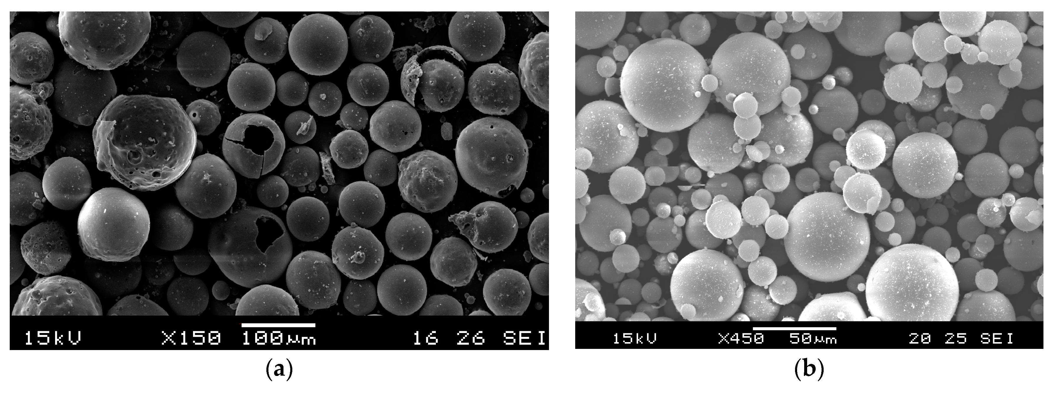
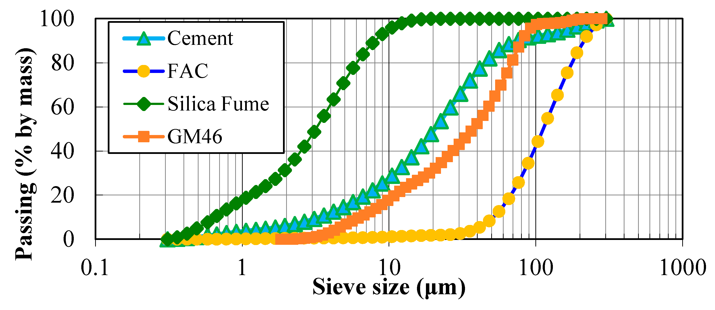
The used FAC and GM had a relatively smooth surface and were composed of a closed external shell and internal air pores encapsulated within the shell. This could be the reason that the GM and FAC had lower water absorption (less than 2% after soaking in water for 1 h) compared to the other available lightweight aggregates (LWAs). Glass microspheres used in this paper had a diameter in the range of 2–125 microns with wall thicknesses less than 1 micron. Figure 2a,b shows the SEM image of two types of cenospheres (FAC and GM) and both aggregates are almost intact and have good spherical shape. Particle size distribution of these two materials is illustrated in Figure 3. Glass microspheres had fineness comparable to that of cement with mean particle size of 40 μm.
To improve the flexural strength and ductility of FLCC, different amounts in volume of polyethylene (PE) fibers were employed. PE fiber has a tensile strength around 2900 MPa with an elastic modulus of 116 GPa. The aspect ratio of PE fiber (fiber length to diameter ratio) is 720. According to the information from the manufacturer, the PE fibers were not surface treated. A total of three mixtures were added with PE fiber ranging from 0.5% to 1.5% in an interval by volume.
2.2. Mix Proportion
Floatable, lightweight cement composite was cast using above-mentioned OPC, superplasticizer, silica fume, and glass microspheres with a water/binder ratio of 0.35 to 0.65. Due to the fine particle size and corresponding larger specific surface area of the glass microspheres, more water should be used, hence a w/b of 0.6 was chosen based on trial tests. The density of lightweight fine aggregate affects the density of FLCC considerably, since the volume of aggregate is significant in the mixtures. Three types of glass microsphere aggregates with a mass ratio of 0.6 were considered in the mix proportions. Another two control mixes were ULCC using fly ash cenospheres and LWC using expanded shale aggregates. The mix proportions of FLCC, ULCC, and LWC are summarized in Table 5. Trial batches were made to obtain the desired density, slump flow, and strength, therefore the contents of superplasticizer and fine aggregates were adjusted.
2.3. Mixing Procedures
Unlike normal concrete, making FLCC requires longer mixing time due to the fine nature of the microspheres, while the spherical shape provides a ball-bearing effect and ensures better flowability of the FLCC. For workability measurement, the fresh FLCC mixture was placed in a truncated conical mold on a plastic board [55]. The FLCC spread out on the board after lifting the mold vertically. Time for the FLCC to reach a diameter of 200 mm and final average spread diameter in two directions were measured for evaluation of the workability. Due to the ball-bearing effect of glass microspheres, the successful FLCC mixture is a highly workable composite similar to the cement grout which is suitable for pumping and grouting in construction. It should be noted that the quality control of producing the FLCC needs to be considered carefully. A high-shear mixer should be adopted to improve the distribution of fibers when mixing FLCC. Due to the use of microaggregates, FLCC can be adopted for advanced extrusion methods and 3D printing technology, provided that adequate quality control exists. Then, less porosity and denser microstructure can be achieved, leading to better mechanical properties.
2.4. Test Methods
Table 6 lists the test method references and specimen size for measuring the mechanical and functional properties of FLCC. The workability was performed immediately after production of FLCC according to British Standard EN 1015-3 [55]. The fresh density and air content were measured in general compliance with the standard procedures in ASTM C138 [56]. The 100 mm diameter, 200 mm long cylindrical specimens, and 50 mm cube specimens were used to determine the density in hardened concrete. The compressive strength, modulus of elasticity, and Poisson’s ratio of the cylindrical specimens were measured according to ASTM C39 [57], ASTM C109 [58], and ASTM C 469 [59], respectively. The modulus of elastic values of FLCC specimens was also calculated by Equation (1) to (2), given by ACI 318 [60] and CEB FIP code [6], respectively.
where E = modulus of elasticity, w = air dry density of concrete, σ = compressive strength.
The flexural strength of FLCC was measured using three-point bending on 40 × 40 × 160 mm prism specimens according to BS EN 196-1 [61]. Additionally, the compressive strength of FLCC can be calibrated using portions of prisms broken in flexure following ASTM C349 [62]. To demonstrate the feasibility of using FLCC as a lightweight engineering cement composite (ECC) with strain-hardening properties, direct tensile tests on FLCC incorporating PE fibers were also conducted using three dogbone-shaped specimens recommended by the Japan Society of Civil Engineers (JSCE) [63] for standardized testing of ECC at the age of 28 days.
The thermal conductivity of the FLCC and normal concrete specimens was determined according to ASTM C518 [64] by a heat flow meter and ASTM C177 [65] using guarded hot plate equipment. The results reported in this paper were the average value from two 300 mm × 300 mm × 50 mm plate specimens. The 300 mm × 300 mm × 50 mm plate specimens used were first moist cured for 28 days, and then dried in a laboratory environment for two weeks followed by drying in an oven at 105 °C until constant weight was obtained. For the tests in this paper, about two months were needed to achieve a constant weight.
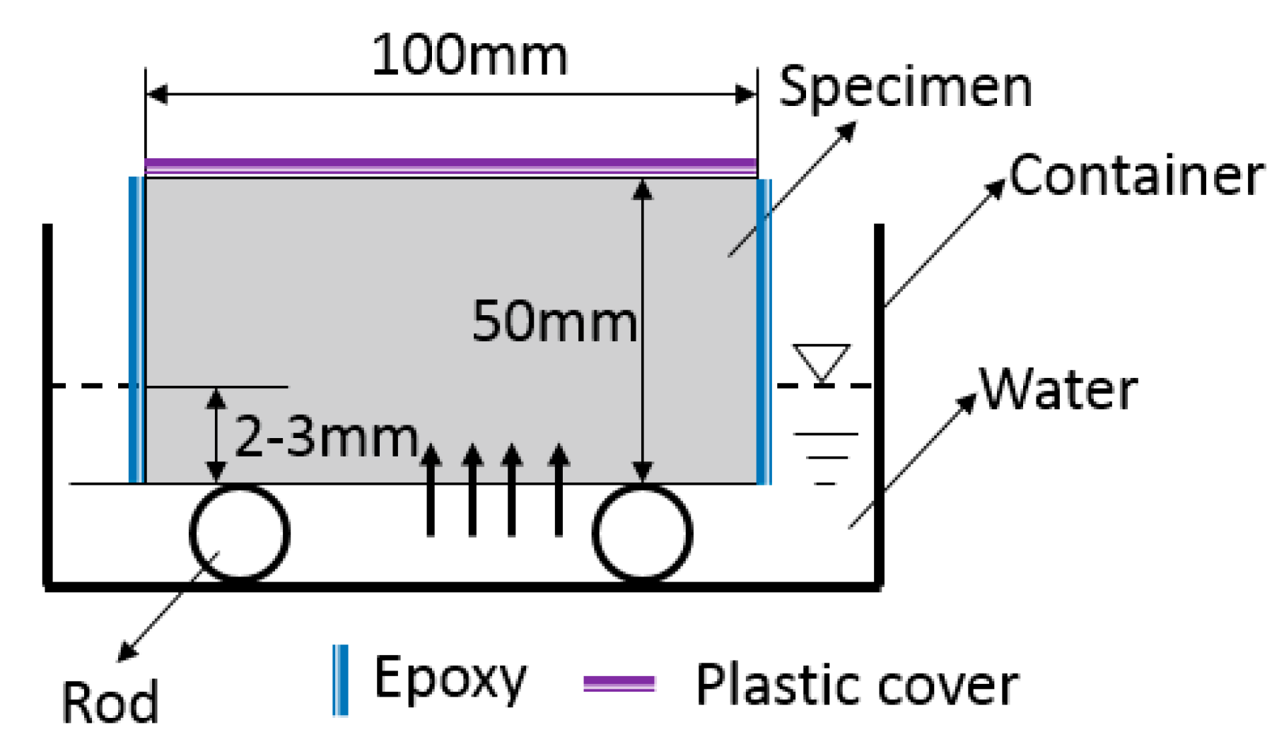
The sorptivity test is a useful test to examine the effectiveness of any water-repellent materials. Sorptivity of FLCC, ULCC, NWC, and LWC was determined by measuring the weight increase of a specimen due to the absorption of water as a function of time when one surface of the specimen was exposed to water according to ASTM C 1585 [66]. Figure 4 shows the test setup for the FLCC sorptivity test. Both ends of the specimens were well grinded. The specimens were placed in an environmental chamber at a temperature of 50 °C and relative humidity of 80% for 3 days before being stored in a sealable plastic bag at 23 ± 2 °C for 15 days. The specimens were coated with epoxy on side surfaces to allow only one surface of the specimen to be in contact with water, with a depth of water between 2 and 3 mm (Figure 4). The top surface of the specimens was covered to prevent evaporation during the test. The bottom surface was in contact with water and the weight increase of the specimen was monitored at times. The test consisted of registering the increase at given intervals of time (1, 2, 3, 4, 6, and 24 h) when permitted to absorb water by capillary suction. According to ASTM C 1585, two parameters, (1) initial water absorption, namely, the quantity of water absorbed by a unit surface area during the first hour of the test, and (2) sorptivity parameter, namely, the slope of the linear regression curve of the quantity of water absorbed by a unit surface area versus square root of the elapsed time from 1 to 24 h, were calculated.
3. Experimental Results
3.1. Density, Workability, Air Content, and Compressive Strength
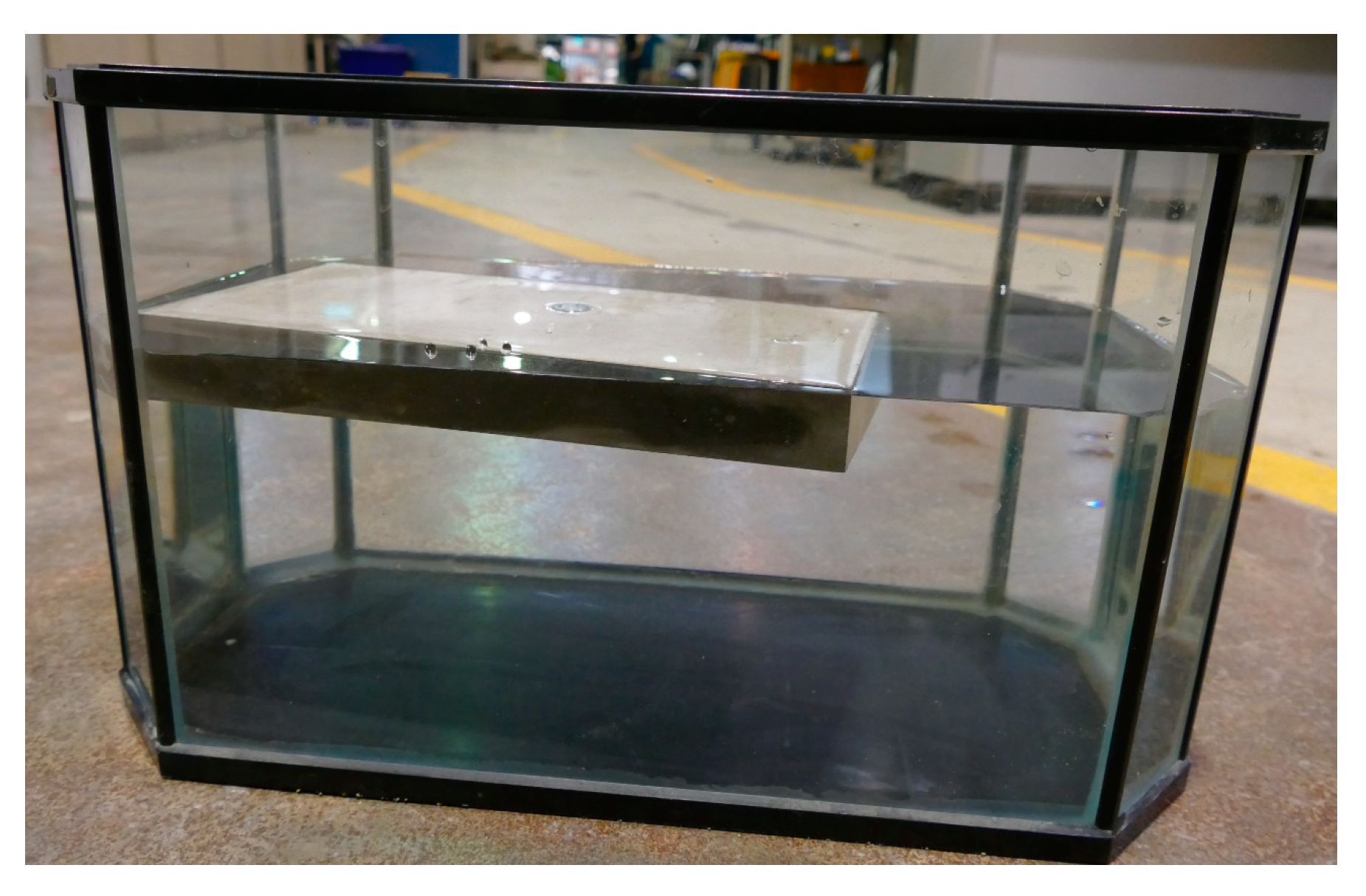
Table 7 summarizes the measured properties of FLCC, including flow value, density, 28-day compressive strength, and flexural strength. The average fresh density of FLCC obtained ranges of 880–970 kg/m3. During the mixing, it was found that a higher amount of superplasticizer was needed, which was due to the larger specific surface area of lightweight glass microspheres compared to the normal angular particles of crushed stone aggregates. Increasing the amount of the glass microspheres resulted in a corresponding decrease in the compressive strength and density. Different amounts of PE fiber addition resulted in different increases of flexural strength but in certain reductions of compressive strength. The 28-day compressive strength of FLCC ranged from 26.9 MPa to 41.0 MPa. This is a promising property that indicates FLCC could be used as a structural cement composite material in terms of compressive strength. The high strength of FLCC may be due to: (1) the high strength of the fine glass microsphere aggregate itself, and (2) the three-dimensional confinement effect from the surrounding hardened cement matrix when subjected to loading, which is attributed to uniform distribution of glass microspheres in the cement matrix. Among those mixtures, FL40 had the highest compressive strength of up to 41 Mpa, followed by FL46 and FL60 with slightly lower compressive strengths. Interestingly, it was found that while the decrease in compressive strength from FL40 to FL46 corresponded to the reduction in density, the decrease in compressive strength from FL46 to FL60 was much higher, indicating that a threshold may exist in terms of the type and density of GM that can be added to cement composites. Therefore, FL46 was chosen as the optimal type of GM for other mixes, including those containing PE fibers. For a given w/b ratio of 0.6, the FL60 sample had a higher porosity in the cement paste matrix but lower porosity in the microspheres compared with FL40 and FL46. Compared to a w/b ratio of 0.35, FL46-35 had a higher porosity of 7.51%, which may be due to the low w/b ratio. The densities of all FLCC were less than the density of water, which indicated that the FLCC concrete can float on the water. Figure 5 shows a floating sample of FLCC when it was placed in water. A more promising behavior was that a broken FLCC segment could also float on water, indicating that glass microsphere aggregates were uniformly distributed in the cement matrix. This suggests that even if failure of a structure using FLCC occurs, it would not sink into the water.
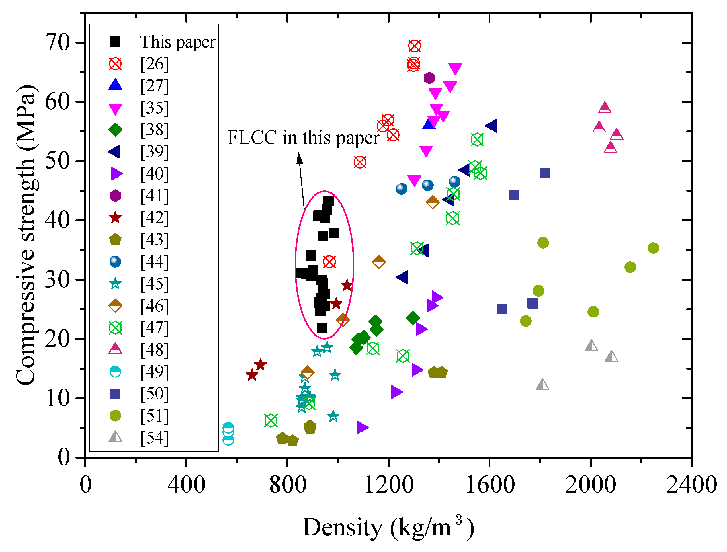
Figure 6 shows the database of lightweight concrete using fly ash cenospheres and glass microspheres in terms of density and compressive strength (fcm). Both the test data in this paper and those from literature are plotted in the figure. Compared to other types of lightweight concrete, FLCC developed in this paper exhibited much higher specific strength (compressive strength-to-density ratio was from 28.6 to 42.3 kPa/kg·m−3, while for S355 steel it was 45.2 kPa/kg·m−3). Also, among the test data with density below 1000kg/m3, FLCC showed promising performance with compressive strength (fcm) exceeding 40 MPa. For concrete with density grade between 1000 kg/m3 and 1300 kg/m3, FAC-based ULCC exhibited the highest specific strength up to 53.3 kPa/kg·m−3 [26,35].
3.2. Flexural and Tensile Strength
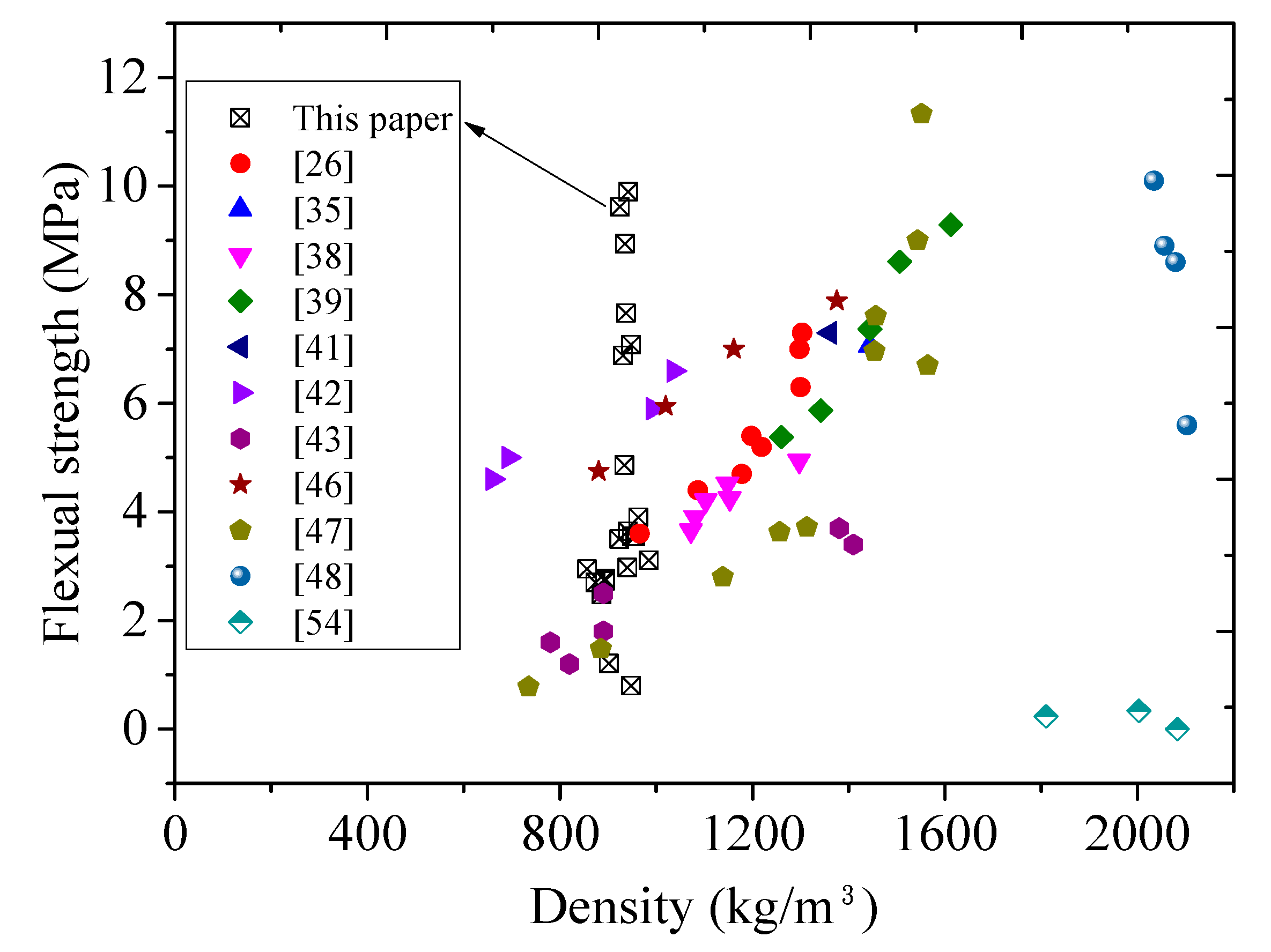
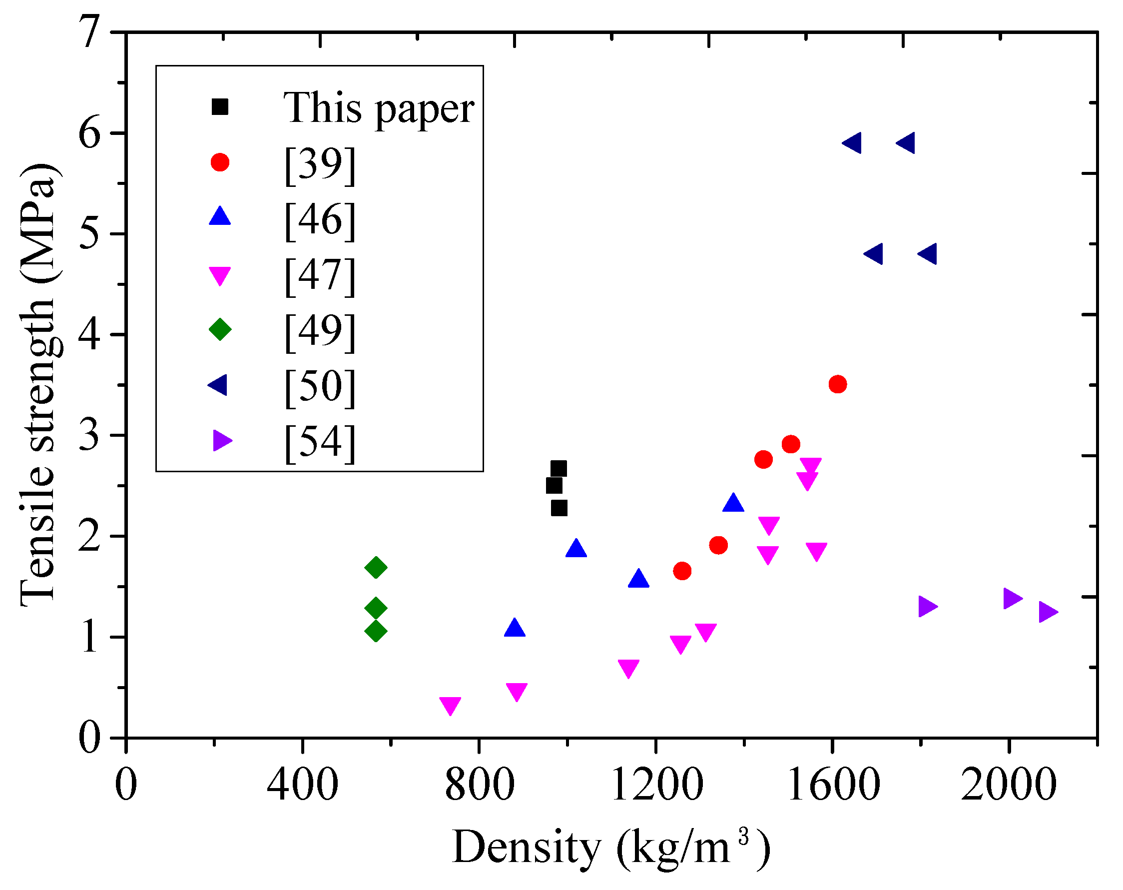
With the addition of 0.5%, 1.0%, and 1.5% PE fiber, the flexural strength (fct) increased by about 80.3%, 223.3%, and 325.6%, respectively, compared to that without fiber addition. The average 28-day flexural strength through three-point bending test ranged from 4.0 MPa to 9.5 MPa. Figure 7 and Figure 8 plot the relationship between flexural/tensile strength and density of published lightweight concrete using FAC or GM, respectively, showing that FLCC possessed the highest flexural/tensile strength for 1000 kg/m3 grade ultralightweight cement composite.
To check if the FLCC can be developed as a lightweight cement composite with strain-hardening properties, direct tensile tests on FLCC incorporating PE fibers were conducted using three dogbone specimens at the age of 28 days. The representative stress–strain curves of FLCC with 1% and 1.5% PE fibers are shown in Figure 9a. It was found that the direct tensile strain capacity of these two mixtures exhibited strain-hardening behavior under direct tensile load. The maximum tensile strains both exceeded 3%, up to about 5–6%, which is higher than that of normal ECC [67]. Multiple cracks were observed, initiating and propagating all over the specimen surface. Figure 9b also shows the residual crack pattern of FLCC after the tensile test. These behaviors suggest that the developed FLCC incorporated with a low amount of PE fibers (less than 2%) is qualified for the development of high-ductility ECC. The glass-microsphere-based cement matrix satisfies the micromechanics-based design criteria for strain-hardening cement composites which are: (1) the tensile first-cracking strength must not exceed the maximum fiber-bridging strength, and (2) the maximum energy available for steady-state flat crack propagation much exceed the energy required for matrix breakdown [68]. Potentially, FLCC with PE fiber used in this paper could be developed as a novel type of ultralightweight, strain-hardening cement composite. Nevertheless, this paper only handles the preliminary behavior of FLCC, while design method and performance evaluation on such ultralightweight, strain-hardening cement composites need further study.
3.3. Elastic Modulus
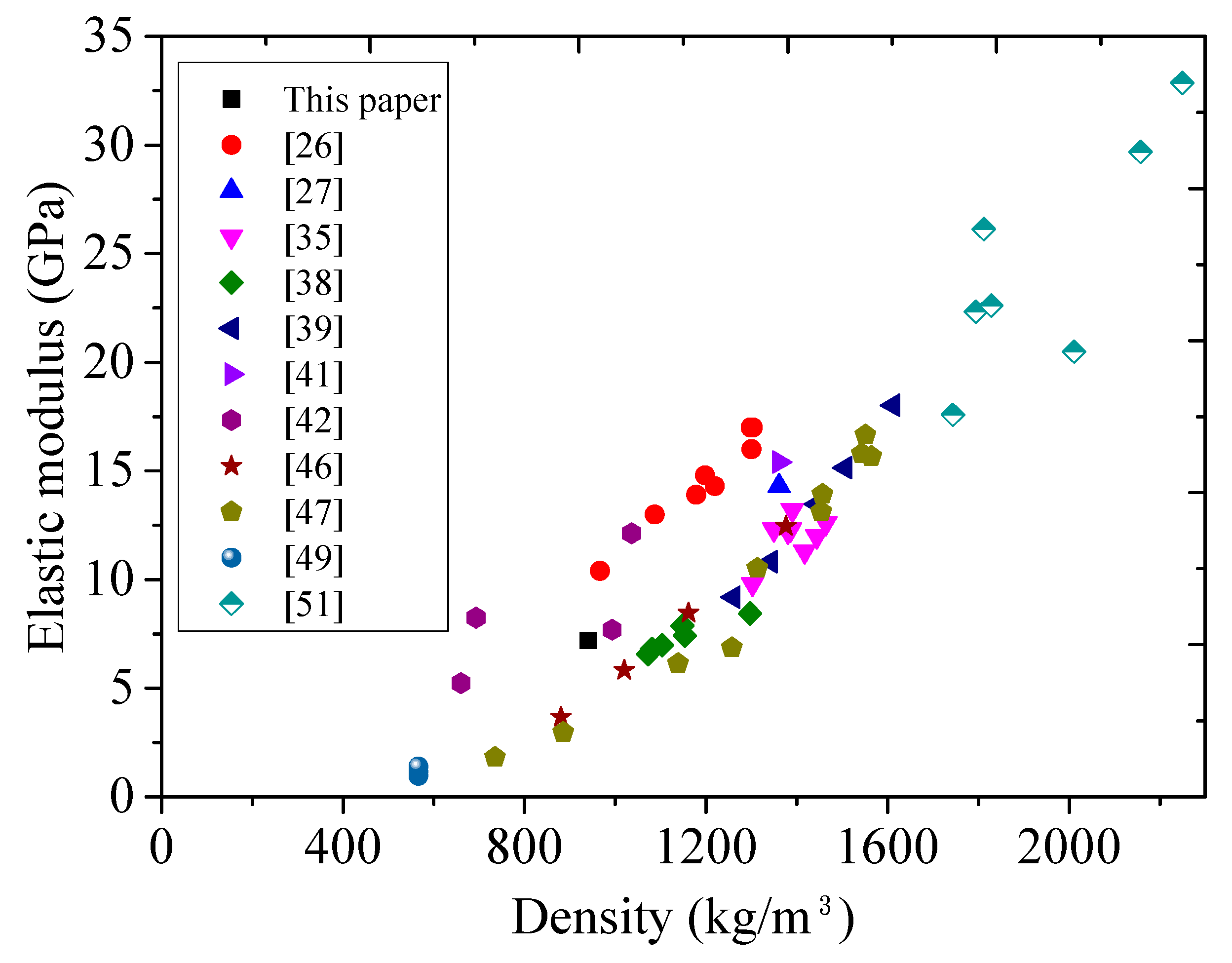
The modulus of elasticity and Poisson’s ratio of FLCC are 7.2 GPa and 0.25, respectively, based on ASTM C469. Figure 10 plots the relationship between elastic modulus and density of published lightweight concrete using cenospheres and glass microspheres. In general, the elastic modulus is proportional to the density of the FLCC. Compared to ULCC and normal LWC, FLCC has lower density and elastic modulus due to lower elastic modulus of glass microsphere aggregates, but with comparable compressive and flexural strength. This fact may challenge the serviceability design for flexural-dominated structural members in future applications. However, the drawback of low elastic modulus can be addressed by metal-FLCC composite design, which could be a reasonable engineering solution.
3.4. Sorptivity
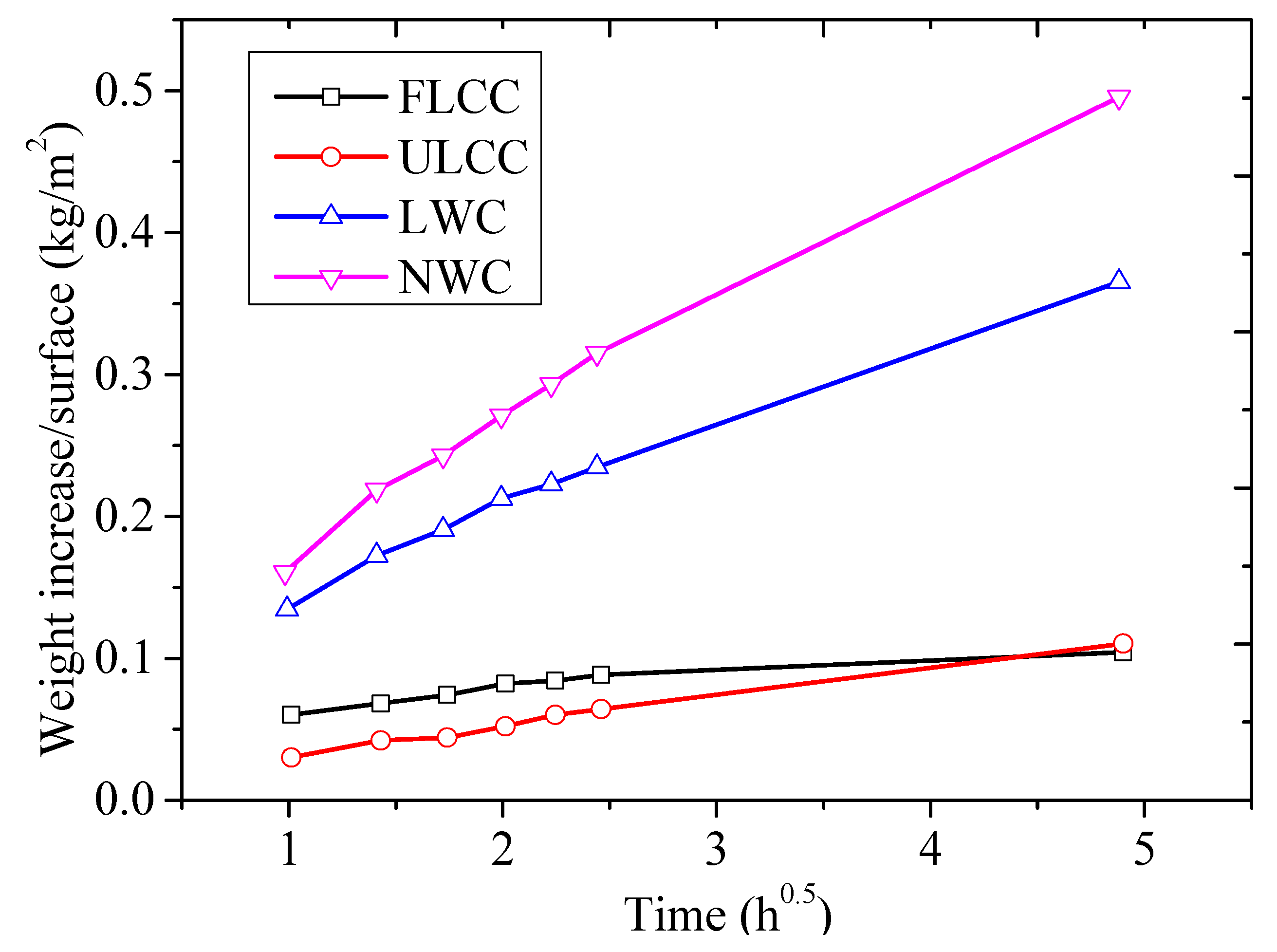
In this paper, the mix FL46 was selected for the sorptivity test. Three Ф 100 mm × Ф 50 mm specimens were cut from a Ф 100 × Ф 200 mm cylinder after the 28-day moist curing. Figure 11 compares the average weight increase due to water absorption against time of different concretes, including FLCC, ULCC, LWC, and NWC. It was found that FLCC had lower water absorptivity compared to that of normal-weight concrete and lightweight aggregate concrete, and had similar water absorptivity with ULCC, which is essential to retain low unit weight if FLCC is exposed in a marine environment.
3.5. Thermal Conductivity
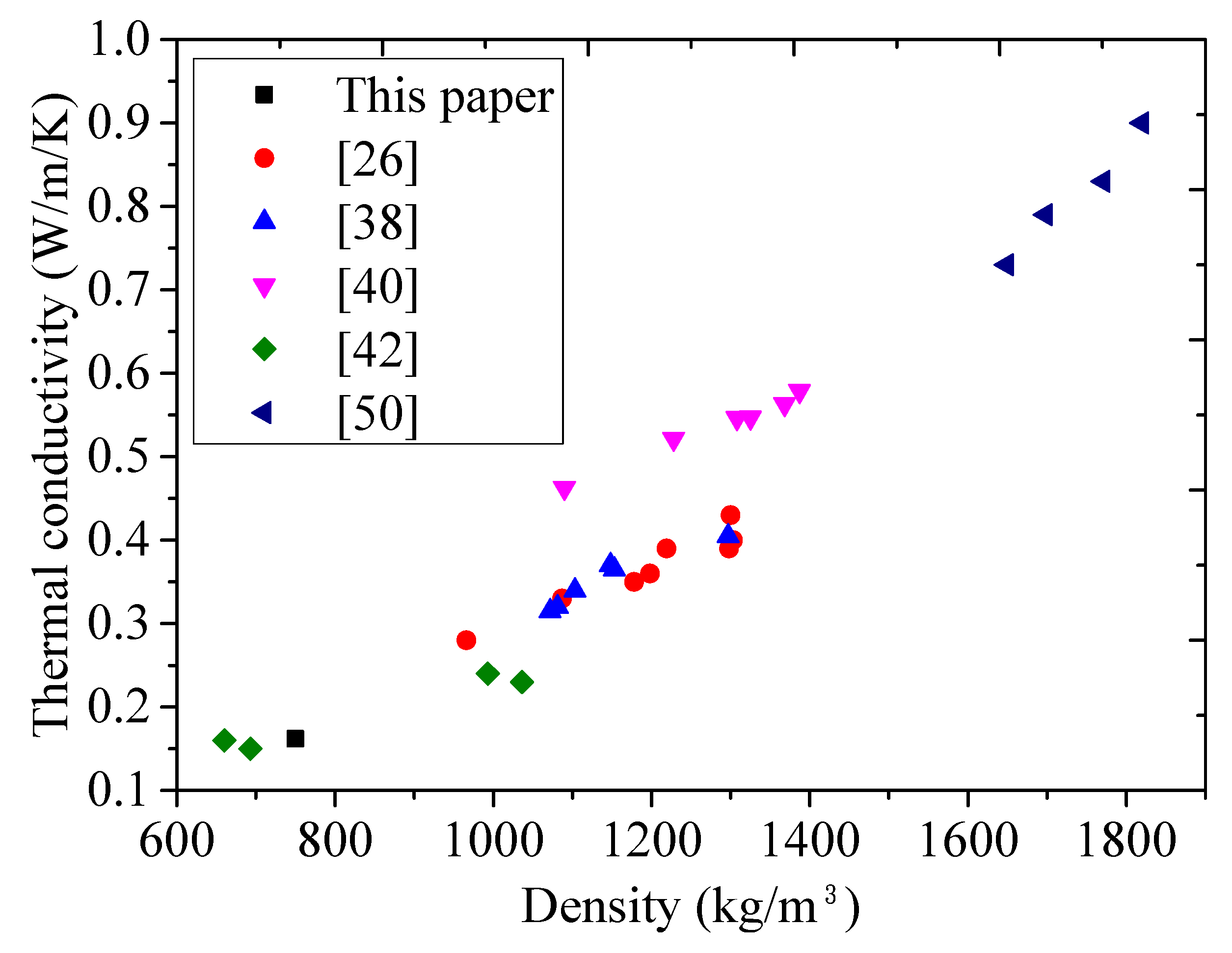
Two FLCC specimens were prepared for thermal conductivity measurement. Figure 12 shows the relationship between thermal conductivity and density for lightweight concrete using FAC and glass microspheres. While the thermal conductivity is dependent on a number of factors, such as moisture content, type of aggregates, w/b ratio, and so forth, the most important parameter affecting the thermal conductivity is the density. Introduction of air voids lowers the density and decreases the thermal conductivity of concrete. The lower the density of lightweight concrete, the smaller the thermal conductivity when ignoring the moisture content. Glass microspheres have lighter weight and lower thermal conductivity (0.03–0.044 W/mK) than that of FAC (0.065–0.08 W/mK) and other denser aggregates (sand and granite: 2.6 W/mK). From Table 8, comparing ULCC-6 with w/b ratio of 0.56, and FL46 with w/b of 0.60, the difference in density is mainly due to the density of microspheres and therefore, the difference in the thermal conductivity may be attributed to the glass microspheres. The thermal conductivity of the FLCC (0.162 W/mK) at ambient temperature (30 °C) was 42% lower than that of the ULCC-6 (0.28 W/mK), while that of ULCC-1 was 80% lower than that of the normal concrete (1.98 W/mK) (Table 8). It is known that the heat transfer through opaque envelopes is directly related to its thermal conductivity. Therefore, adopting FLCC with low thermal conductivities can result in lower heat transmitted inside the building. This is especially beneficial in warm climates to reduce the energy incurred by air conditioning. As temperature increased, the thermal conductivity of FL46 increased from 0.154 to 0.162 and 0.180 W/mK, respectively, from 10 °C to 30 °C and 90 °C. But the increment was very small. Due to the limitation of the test facility in this paper, only the thermal conductivity of FLCC below 100 °C was measured. To simulate and analyze the thermal behavior of buildings made of these types of thermally insulating, lightweight cement composites under fire, it is also needed to obtain the thermal conductivity of FLCC under elevated temperature in future study.
3.6. Microstructural Characterization
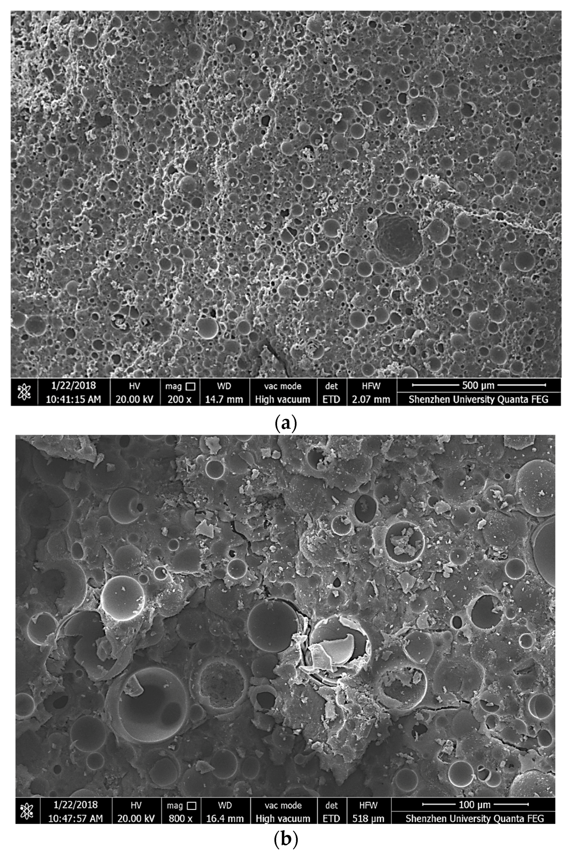
The morphological and microstructural characterizations of the samples from the damaged concrete segments after the compression test on FLCC cubes were analyzed with a scanning electron microscope (Phenom pro). The test samples were soaked in isopropanol to stop the hydration, and then vacuum-dried in the oven at 40 °C before testing. Figure 13 illustrates the SEM image of FLCC at different magnifications. The microstructure of dense matrix and homogeneous GM can be observed in the composites. In general, the microspheres seemed well distributed in the matrix. Further, the shell of the glass microspheres remained intact even after moist curing for 28 days, indicating that there was little or no interaction between the microspheres and the paste. This means that the glass microspheres can be utilized in cement-based composites. Under stress, the crack initiates from the interfacial transition zone between cement matrix and glass microspheres as shown in Figure 13b. This is contrary to behavior exhibited by lightweight aggregate concrete (LWC), where the crack initiation occurs due to the failure of the aggregates. This figure also shows that glass microspheres offer resistance to crack growth, leading to matrix cracking and debonding prior to GM particle breakage. This is due to the lower strength of the matrix compared to that of GM particles used in this paper that may hinder the crack growth.
4. Conclusions
This paper presents a new type of multifunctional, floatable, lightweight cement composite (FLCC) with densities lower than that of water (oven-dry density of 750 kg/m3) and compressive strength (fcm) up to 41 MPa by means of commercially available glass microspheres. A range of properties was investigated for seven different types of FLCC, and FLCC using GM46 was found to have optimal compressive and flexural strength. Addition of 1.5% PE fiber in volume improves the flexural strength by more than 3 times. Under direct tension, FLCC incorporating a low content of PE fiber (1% in volume) exhibits strain-hardening behavior with ultimate tensile strain capacity of 6%. Thus, an ultralightweight FLCC (lightweight ECC) with strain-hardening characteristics has been produced for wider engineering applications. However, the elastic modulus was lower than normal concrete and lightweight concrete due to the lower elastic modulus of the glass microsphere aggregates. The FLCC also exhibited better water absorption capacity and much superior thermal insulation properties. The use of FLCC developed in this paper enables novel metal/polymer-FLCC composite structures to be further developed with lower self-weight, which will provide alternatives for prefabricated concrete structures, marine construction, and ship hulls. This will benefit the transportation and installation of precast and mass-sensitive structures.
Author Contributions
Z.H. conceived and designed the experimental work; F.W. completed the experiments; Y.Z. provided constructive ideas on the work; L.S. provided constructive comments on the experimental plan; P.K. analyzed the test results and performed paper editing; J.-Y.R.L. proposed the original idea; and all the authors participated in writing and revising this paper.
Funding
This research was funded by National Natural Science Foundation of China (No.51708360, No.51778371), Ministry of Education (MOE) in Guangdong Province (No.2017KTSCX164), and Scientific Research Startup Fund of Shenzhen University (No.2018023).
Acknowledgments
Acknowledgement is made to Air Conditioning Laboratory, Mechanical Engineering Department National University of Singapore, and Wu Yunpeng for assistance in determining the thermal conductivity of cement pastes and concrete.
Conflicts of Interest
The authors declare no conflict of interest.
References
- Liew, J.Y.R.; Huang, Z.Y. Lightweight Steel-Concrete Composite Flooring—Recent Innovation. In Proceedings of the 9th International Symposium on Steel Structures, Jeju, Korea, 1–4 November 2017; pp. 655–658. [Google Scholar]
- Huang, Z.Y.; Liew, J.Y.R. Lightweight Composite Flooring for PPVC—Residual Mechanical Behaviour of ULCC after Exposing to Elevated Temperature. In Proceedings of the 9th International Symposium on Steel Structures, Jeju, Korea, 1–4 November 2017; pp. 659–662. [Google Scholar]
- Huang, Z.Y.; Liew, J.Y.R. Compressive resistance of steel-concrete-steel sandwich composite walls with J-hook connectors. J. Constr. Steel Res. 2016, 124, 142–162. [Google Scholar] [CrossRef]
- Deep Water—The Next Step for Offshore Wind Energy. Available online: http://www.ewea.org/fileadmin/files/library/publications/reports/DeepWater.pdf (accessed on 31 July 2013).
- Taghipour, R.; Moan, T. Efficient frequency-domain analysis of dynamic response for the multi-body wave energy converter in multi-directional wave. In Proceedings of the Eighteenth International Offshore and Polar Engineering Conference. Vancouver, BC, Canada, 6–11 July 2008. [Google Scholar]
- CEB-FIP. FIP Model Code for Concrete Structures; Comité Euro-International du Béton: Lausanne, Switzerland, 2013. [Google Scholar]
- ASTM 213R-14 Guide for Structural Lightweight-Aggregate Concrete; American Society of Testing and Materials: West Conshohocken, PA, USA, 2014.
- ASTM C330/C330M-14 Standard Specification for Lightweight Aggregates for Structural Concrete; American Society of Testing and Materials: West Conshohocken, PA, USA, 2014.
- BS EN 13055. Lightweight Aggregates. Part 1 Lightweight Aggregates. Lightweight Aggregates for Concrete, Mortar and Grout; British Standards Institution: London, UK, 2016. [Google Scholar]
- JGJ 51-02, Technical Specification for Lightweight Aggregate Concrete; Chinese Code: Beijing, China, 2002.
- Lotfy, A.; Hossain, K.M.A.; Lachemi, M. Mix design and properties of lightweight self-consolidating concretes developed with furnace slag, expanded clay and expanded shale aggregates. J. Sustain. Cem. Based Mater. 2015, 5, 297–323. [Google Scholar] [CrossRef]
- Kramar, D.; Bindiganavile, V. Impact response of lightweight mortars containing expanded perlite. Cem. Concr. Compos. 2013, 37, 205–214. [Google Scholar] [CrossRef]
- Yu, R.; Onna, D.V.V.; Spiesz, P.; Yu, Q.L.; Brouwersa, H.J.H. Development of Ultra-Lightweight Fibre Reinforced Concrete applying expanded waste glass. J. Clean. Prod. 2016, 112, 690–701. [Google Scholar] [CrossRef]
- Liu, X.M.; Chia, K.S.; Zhang, M.H. Development of lightweight concrete with high resistance to water and chloride-ion penetration. Cem. Concr. Compos. 2010, 32, 757–766. [Google Scholar] [CrossRef]
- Babu, D.S.; Babu, K.G.; Wee, T.H. Properties of lightweight expanded polystyrene aggregate concretes containing fly ash. Cem. Concr. Res. 2005, 35, 1218–1223. [Google Scholar] [CrossRef]
- Işıkdağ, B. Characterization of lightweight ferrocement panels containing expanded perlite-based mortar. Constr. Build. Mater. 2015, 81, 15–23. [Google Scholar] [CrossRef]
- Amran, Y.H.M.; Farzadnia, N.; Ali, A.A.A. Properties and applications of foamed concrete: A review. Constr. Build. Mater. 2015, 101, 990–1005. [Google Scholar] [CrossRef]
- Lim, S.K.; Tan, C.S.; Lim, O.Y.; Lee, Y.L. Fresh and hardened properties of lightweight foamed concrete with palm oil fuel ash as filler. Constr. Build. Mater. 2013, 46, 39–47. [Google Scholar] [CrossRef]
- Putman, B.J.; Neptune, A.I. Comparison of test specimen preparation techniques for pervious concrete pavements. Constr. Build. Mater. 2011, 25, 3480–3485. [Google Scholar] [CrossRef]
- Neville, A.M. Properties of Concrete, 5th ed.; Pearson: London, UK, 2011. [Google Scholar]
- Chandra, S.; Berntsson, L. Lightweight Aggregate Concrete Science, Technology and Applications; Standard Publishers Distributors: Delhi, India, 2003; ISBN 81-8014-052-0. [Google Scholar]
- Mydin, M.A.O.; Wang, Y.C. Structural performance of lightweight steel-foamed concrete-steel composite walling system under compression. Thin-Walled Struct. 2011, 49, 66–76. [Google Scholar] [CrossRef]
- Prabha, P.; Marimuthu, V.; Saravanan, M.; Palani, G.S.; Lakshmanan, N.; Senthil, R. Effect of confinement on steel-concrete composite light-weight load-bearing wall panels under compression. J. Constr. Steel Res. 2013, 81, 11–19. [Google Scholar] [CrossRef]
- He, Y.; Zhang, X.; Zhang, Y.; Zhou, Y. Effects of particle characteristics of lightweight aggregate on mechanical properties of lightweight aggregate concrete. Constr. Build. Mater. 2014, 72, 270–282. [Google Scholar] [CrossRef]
- Hassanpour, M.; Shafigh, P.; Mahmud, H.B. Lightweight aggregate concrete fiber reinforcement—A review. Constr. Build. Mater. 2012, 37, 452–461. [Google Scholar] [CrossRef]
- Wu, Y.P.; Wang, J.Y.; Monteiro, P.J.M.; Zhang, M.H. Development of ultra-lightweight cement composites with low thermal conductivity and high specific strength for energy efficient buildings. Constr. Build. Mater. 2015, 87, 100–112. [Google Scholar] [CrossRef]
- Huang, Z.Y.; Liew, J.Y.R.; Xiong, M.X.; Wang, J.Y. Structural behaviour of double skin composite system using ultra-lightweight cement composite. Constr. Build. Mater. 2015, 86, 51–63. [Google Scholar] [CrossRef]
- Huang, Z.Y.; Wang, J.Y.; Liew, J.Y.R.; Marshall, P.W. Lightweight steel–concrete–steel sandwich composite shell subject to punching shear. Ocean Eng. 2015, 102, 146–161. [Google Scholar] [CrossRef]
- Huang, Z.Y.; Liew, J.Y.R. Numerical studies of steel-concrete-steel sandwich wall subjected to axial loads. Steel Compos. Struct. 2016, 21, 461–477. [Google Scholar] [CrossRef]
- Huang, Z.Y.; Liew, J.Y.R. Nonlinear finite element modelling and parametric study of curved steel-concrete-steel double skin composite panel filled with ultra-lightweight cement composite. Constr. Build. Mater. 2015, 95, 922–938. [Google Scholar] [CrossRef]
- Huang, Z.Y.; Liew, J.Y.R. Structural behaviour of steel-concrete-steel sandwich composite wall subjected compression and end moment. Thin-Walled Struct. 2016, 98, 592–606. [Google Scholar] [CrossRef]
- Huang, Z.Y.; Liew, J.Y.R. Experimental and analytical studies of curved steel–concrete–steel sandwich panels under patch loads. Mater. Des. 2016, 93, 104–117. [Google Scholar] [CrossRef]
- Wang, J.Y.; Chia, K.S.; Liew, J.Y.R.; Zhang, M.H. Flexural performance of fiber reinforced ultra-lightweight cement composites with low fiber content. Cem. Concr. Compos. 2013, 43, 39–47. [Google Scholar] [CrossRef]
- Huang, Z.Y.; Liew, J.Y.R.; Li, W. Evaluation of compressive behavior of ultra-lightweight cement composite after elevated temperature exposure. Constr. Build. Mater. 2017, 148, 579–589. [Google Scholar] [CrossRef]
- Huang, Z.; Padmaja, K.; Li, S.; Richard Liewc, J.Y. Mechanical properties and microstructure of ultra-lightweight cement composites with fly ash cenospheres after exposure to high temperatures. Constr. Build. Mater. 2018, 164, 760–774. [Google Scholar] [CrossRef]
- Lu, Z.; Hanif, A.; Lu, C.; Liu, K.; Sun, G.; Li, Z. A Novel Lightweight Cementitious Composites with Enhanced Thermal Insulation and Mechanical Properties by Extrusion Technique. Constr. Build. Mater. 2018, 163, 446–449. [Google Scholar] [CrossRef]
- Chia, K.S.; Liu, X.M.; Liew, J.Y.R.; Zhang, M.H. Creep and shrinkage of ultra lightweight cement composite. In Proceedings of the 2013 World Congress on Advances in Structural Engineering and Mechanics, Jeju, Korea, 8–12 September 2013; pp. 3283–3297. [Google Scholar]
- Hanif, A.; Diao, S.; Lu, Z.; Fan, T.; Li, Z. Green lightweight cementitious composite incorporating aerogels and fly ash cenospheres—Mechanical and thermal insulating properties. Constr. Build. Mater. 2016, 116, 422–430. [Google Scholar] [CrossRef]
- Hanif, A.; Lu, Z.; Diao, S.; Zeng, X.; Li, Z. Properties investigation of fiber reinforced cement-based composites incorporating cenosphere fillers. Constr. Build. Mater. 2017, 140, 139–149. [Google Scholar] [CrossRef]
- Blanco, F.; Garcı́a, P.; Mateos, P.; Ayala, J. Characteristics and properties of lightweight concrete manufactured with cenospheres. Cem. Concr. Res. 2000, 30, 1715–1722. [Google Scholar] [CrossRef]
- Huang, Z.; Liew, J.Y.R. Steel-concrete-steel sandwich composite structures subjected to extreme loads. Int. J. Steel Struct. 2016, 16, 1009–1028. [Google Scholar] [CrossRef]
- Oreshkin, D.; Semenov, V.; Rozovskaya, T. Properties of Light-weight Extruded Concrete with Hollow Glass Microspheres. Procedia Eng. 2016, 153, 638–643. [Google Scholar] [CrossRef]
- Perfilov, V.A.; Oreshkin, D.V.; Semenov, V.S. Environmentally Safe Mortar and Grouting Solutions with Hollow Glass Microspheres. Procedia Eng. 2016, 150, 1479–1484. [Google Scholar] [CrossRef]
- Korolev, E.V.; Inozemtcev, A.S. Preparation and Research of the High-Strength Lightweight Concrete Based on Hollow Microspheres. Adv. Mater. Res. 2013, 746, 285–288. [Google Scholar] [CrossRef]
- Semenov, V.; Rozovskaya, T. Light-weight Dry Masonry Mixes with Hollow Ceramic Microspheres for Winter Conditions. Procedia Eng. 2016, 153, 623–629. [Google Scholar] [CrossRef]
- Hanif, A.; Parthasarathy, P.; Lu, Z.; Sun, M.; Li, Z. Fiber—Reinforced Cementitious Composites Incorporating Glass Cenospheres—Mechanical properties and Microstructure. Constr. Build. Mater. 2017, 154, 529–538. [Google Scholar] [CrossRef]
- Hanif, A.; Lu, Z.; Cheng, Y.; Diao, S.; Li, Z. Effects of Different Lightweight Functional Fillers for Use in Cementitious Composites. Int. J. Concr. Struct. Mater. 2017, 11, 99–113. [Google Scholar] [CrossRef] [Green Version]
- Al-Gemeel, A.N.; Zhuge, Y.; Youssf, O. Use of hollow glass microspheres and hybrid fibres to improve the mechanical properties of engineered cementitious composite. Constr. Build. Mater. 2018, 171, 858–870. [Google Scholar] [CrossRef]
- Yang, G.; Li, Z.Y. Experimental Study on Ultra-lightweight Fire-resistive Engineered Cementitious Composite. In Proceedings of the International Conference on Advanced Material Engineering, Wuhan, China, 15–17 April 2016; pp. 146–153. [Google Scholar] [CrossRef]
- Huang, X.; Ranade, R.; Zhang, Q.; Ni, W.; Li, V.C. Mechanical and thermal properties of green lightweight engineered cementitious composites. Constr. Build. Mater. 2013, 48, 954–960. [Google Scholar] [CrossRef]
- Yun, T.S.; Jeong, Y.J.; Han, T.S.; Youm, K.S. Evaluation of thermal conductivity for thermally insulated concretes. Energy Build. 2013, 61, 125–132. [Google Scholar] [CrossRef]
- Golewski, G.L. Evaluation of morphology and size of cracks of the Interfacial Transition Zone (ITZ) in concrete containing fly ash (FA). J. Hazard. Mater. 2018, 357, 298–304. [Google Scholar] [CrossRef] [PubMed]
- Golewski, G.L. Generalized Fracture Toughness and Compressive Strength of Sustainable Concrete Including Low Calcium Fly Ash. Materials 2017, 10, 1393. [Google Scholar] [CrossRef] [PubMed]
- Mcbride, S.P.; Shukla, A.; Bose, A. Processing and characterization of a lightweight concrete using cenospheres. J. Mater. Sci. 2002, 37, 4217–4225. [Google Scholar] [CrossRef]
- BS EN 1015-3:1999, Methods of Test for Mortar for Masonry—Part 3: Determination of Consistence of Fresh Mortar (by Flow Table); British Standards Institution: London, UK, 1999.
- ASTM C 138/C 138M–01. Density (Unit Weight), Yield, and Air Content (Gravimetric) of Concrete; American Society of Testing and Materials: West Conshohocken, PA, USA, 2001.
- ASTM C39/C39M-09, Standard Test Method for Compressive Strength of Cylindrical Concrete Specimens; American Society of Testing and Materials: West Conshohocken, PA, USA, 2009.
- ASTM C109/C109M-16a. Standard Test Method for Compressive Strength of Hydraulic Cement Mortars (Using 2-in. or [50-mm] Cube Specimens); American Society of Testing and Materials: West Conshohocken, PA, USA, 2016.
- ASTM C469/C469M–14. Standard Test Method for Static Modulus of Elasticity and Poisson’s Ratio of Concrete in Compression; American Society of Testing and Materials: West Conshohocken, PA, USA, 2014.
- ACI Committee 318. Building Code requirements for Structural Concrete (ACI 318–311) and Commentary (ACI 318R–11); American Concrete Institute: Farmington Hills, MI, USA, 2005.
- BS EN 196-1. Methods of Testing Cement—Part 1: Determination of Strength; British Standards Institution: London, UK, 2005.
- ASTM C349–14. Standard Test Method for Compressive Strength of Hydraulic-Cement Mortars (Using Portions of Prisms Broken in Flexure); American Society of Testing and Materials: West Conshohocken, PA, USA, 2014.
- JSCE, Recommendations for Design and Construction of High-Performance Fiber Reinforced Cement Composites with Multiple fine Cracks; Japan Society of Civil Engineers: Tokyo, Japan, 2008; pp. 1–16.
- ASTM C518-10. Standard Test Method for Steady-State Thermal Transmission Properties by Means of the Heat Flow Meter Apparatus; American Society of Testing and Materials: West Conshohocken, PA, USA, 2010.
- ASTM C177. Standard Test Method for Steady-State Heat Flux Measurements and Thermal Transmission Properties by Means of the Guarded-Hot-Plate Apparatus; American Society of Testing and Materials: West Conshohocken, PA, USA, 2013.
- ASTM, C1585. Standard Test Method for Measurement of Rate of Absorption of Water by Hydraulic-Cement Concretes; American Society of Testing and Materials: West Conshohocken, PA, USA, 2006.
- Yang, E.H.; Li, V.C. Strain-rate effects on the tensile behavior of strain-hardening cementitious composites. Constr. Build. Mater. 2014, 52, 96–104. [Google Scholar] [CrossRef]
- Kanda, T.; Li, V.C. Practical Design Criteria for Saturated Pseudo Strain Hardening Behavior in ECC. Adv. Concr. Technol. 2006, 4, 59–72. [Google Scholar] [CrossRef] [Green Version]
Figure 1.
Onshore and offshore constructions using lightweight concrete: (a) prefabricated modular construction; (b) offshore platform [3]; (c) offshore floater; (d) offshore wind farm [4,5].

Figure 2.
SEM image of lightweight fillers: (a) fly ash cenospheres; (b) glass microspheres (GM46).

Figure 3.
Particle distribution of raw materials.

Figure 4.
Schematic diagram of sorptivity test.

Figure 5.
FLCC specimen floating in a water tank.

Figure 6.
Relationship between compressive strength (fcm) and density of lightweight concrete using cenospheres and glass microspheres.
Figure 6.
Relationship between compressive strength (fcm) and density of lightweight concrete using cenospheres and glass microspheres.

Figure 7.
Relationship between flexural strength (fct) and density of lightweight concrete using cenospheres and glass microspheres.
Figure 7.
Relationship between flexural strength (fct) and density of lightweight concrete using cenospheres and glass microspheres.

Figure 8.
Relationship between tensile strength and density of lightweight concrete using cenospheres and glass microspheres.
Figure 8.
Relationship between tensile strength and density of lightweight concrete using cenospheres and glass microspheres.

Figure 9.
Tensile behavior of FLCC: (a) stress–strain curves of FL46; (b) multiple-cracking behavior.
Figure 9.
Tensile behavior of FLCC: (a) stress–strain curves of FL46; (b) multiple-cracking behavior.

Figure 10.
Relationship between elastic modulus and density of lightweight concrete using cenospheres and glass microspheres.
Figure 10.
Relationship between elastic modulus and density of lightweight concrete using cenospheres and glass microspheres.

Figure 11.
Average weight increase per area against time for different lightweight concretes.

Figure 12.
Relation between thermal conductivity and oven-density for different lightweight concretes.
Figure 12.
Relation between thermal conductivity and oven-density for different lightweight concretes.

Figure 13.
SEM image of fractured surface of FLCC at different magnifications (FL46): (a) 500 μm; (b) 100 μm.
Figure 13.
SEM image of fractured surface of FLCC at different magnifications (FL46): (a) 500 μm; (b) 100 μm.


Table 1.
Specification of lightweight concrete in different codes.
| Code Practice | Density of Lightweight Concrete ρ | 28-day Compressive Strength (fcm) |
|---|---|---|
| CEB-FIP 2010 [6] | Oven-dry: 800–2000 kg/m3 | LC8-LC80 (8–80 MPa) |
| ACI 213R-14 [7] | Air-dry: 1440–1850 kg/m3 | Common value: 21–35 MPa |
| ASTM C330 [8] | 1600–1840 kg/m3 | Common value: 17–28 MPa |
| BS EN 13055-2016 [9] | Not exceeding 2000 kg/m3 | N.A. |
| JGJ 51-2002 [10] | Oven-dry density ≤ 1950 kg/m3 | LC5.0-LC60 (10–38.5 MPa) |
Table 2.
Summary of relevant information in literature.
| Literature | Lightweight Filler | Density ρ (kg/m3) | 28-day Compressive Strength fcm (MPa) | 28-day Flexural Strength fct (MPa) | Specific Strength (kPa/kgm−3) | Elastic Modulus Ec (GPa) | Thermal Conductivity λ (W/mK) |
|---|---|---|---|---|---|---|---|
| Oreshkin et al. [42] | 3MTM Glass Bubbles K25 | 660–993 693–1036 | 13.9–25.9 15.6–29.0 | 4.6–5.9 (non-extruded) 5.0–6.6 (extruded) | 21.1–26.1 22.5–28.0 | – | 0.16–0.24 0.15–0.23 |
| Blanco et al. [40] | Cenospheres from coal–burning power plant | 1090–1510 | 5.04–33.03 | 2.09–5.86 | 4.62–21.9 | – | 0.36–0.44 |
| Perfilov et al. [43] | Coated hollow glass microspheres (HGMS) | 750–1109 | 2.2–3.9 | 0.1–0.8 | 2.93–3.52 | – | – |
| Korolev et al. [44] | Hollow glass microspheres | 1252–1462 | 45.3–46.5 | – | 31.9–36.2 | – | – |
| Semenov et al. [45] | Hollow ceramic microspheres | 857–957 | 8.42–18.5 | 1.98–3.7 | 9.82–19.3 | – | – |
| Mcbride et al. [54] | Ceramic microspheres | 1810–2083 | 12.1–16.9 | 0.24–0.33 | 6.7–8.1 | – | – |
| Hanif et al. [38] | Fly ash cenospheres | 1187–1297 (dry:1003–1098) | 18.6–23.5 | 3.7–4.9 | 15.7–18.1 | 6.57–8.44 | 0.31–0.4 |
| Hanif et al. [39] | Fly ash cenospheres | 1260–1612 | 30.38–55.92 | 5.38–9.29 | 24.11–34.69 | 9.18–18.02 | – |
| Hanif et al. [46] | Glass cenospheres | 880.2–1375.7 | 14.3–43.0 | 4.75–7.89 | 16.2–31.3 | 3.68–12.5 | - |
| Hanif et al. [47] | Glass microspheres Fly ash cenospheres | 734.8–1564.1 1453.9–1551.3 | 6.23–47.9 40.4–53.6 | 0.78–6.7 6.96–11.3 | 8.48–30.6 27.8–34.6 | 1.82–15.7 13.1–16.7 | - |
| Al–Gemeel et al. [48] | Spherical 110P8 hollow glass microspheres | 2034–2158 | 55.5–65.0 | 5.6–14.0 | 27.3–30.1 | - | - |
| Yang and Li [49] | Hollow glass microspheres 3MTM K20 | 566.0–1001.0 | 3.4–5.5 | 1.06–1.69 (tensile) | 6.0–5.49 | 0.96–1.39 | - |
| Huang et al. [50] | Fly ash cenospheres | 1649–1820 | 25.0–47.6 | 4.8–5.9 (tensile) | 15.2–26.2 | - | 0.29–0.37 |
| Yun et al. [51] | Fly ash cenospheres | 2011–2370 | 24.6-43.9 | 1.52–3.16 | 12.2–18.5 | 17.6–39.1 | 1.41–2.21 |
| Wu et al. [26] | Fly ash cenospheres | 1154–1471 | 33.0–69.4 | 3.6–7.3 | 28.6–47.2 | 10.4–17.0 | 0.28–0.4 |
| Huang et al. [35] | Fly ash cenospheres | 1302–1464 | 46.9–65.8 | 7.06 | 36.0–44.9 | 9.8–13.2 | - |
| Huang et al. [41] | Fly ash cenospheres Hollow glass microspheres | 1361 946–969 | 64. 028.1–32.3 | 6.7–8. 0- | 47. 029.7–33.3 | 15.4 - | - |
Table 3.
Chemical composition of cement, silica fume, FAC, and GM.
| Composition | CaO | SiO2 | Al2O3 | Fe2O3 | MgO | K2O | Na2O | B2O3 | SO3 | C3S | C2S | C3A | C4AF |
|---|---|---|---|---|---|---|---|---|---|---|---|---|---|
| Cement | 63.5 | 19.4 | 4.8 | 2.8 | 1.3 | 0.4 | 0.2 | - | 1.9 | 69.0 | 3.6 | 8.1 | 8.4 |
| Silica fume | 0.2 | 94.1 | 0.6 | 0.1 | 0.4 | 0.3 | 0.1 | - | N.A | N.A. | N.A. | N.A. | N.A. |
| FAC | - | 51.6 | 34.6 | - | 0.7 | - | - | - | - | - | - | - | - |
| GM | 13.4 | 72.7 | 1.0 | 0.0 | 0.0 | 0.0 | 6.2 | 6.4 | - | - | - | - | - |
Table 4.
Specification of FAC and GM.
| Type | Bulk Density (g/cm3) | Crushing Strength (MPa) | Moisture Content (%) | Flotation Ratio (%) |
|---|---|---|---|---|
| FAC | 0.45 | 15.0 | 0.2 | 95 |
| GM40 | 0.38–0.42 | 27.6 | 0.5 | 92 |
| GM46 | 0.44–0.48 | 41.3 | 0.5 | 92 |
| GM60 | 0.57–0.63 | 68.9 | 0.5 | 92 |
Table 5.
Mix proportions of FLCC.
| Mix ID | Fillers | Mix Proportion of Matrix by Volume of Total Binder | |||||
|---|---|---|---|---|---|---|---|
| Water/Binder | B 1 | Fillers/B | SP 6/B | Fiber (V%) | |||
| C 2 | SF 3 | ||||||
| ULCC-1 [26] | FAC 4 | 0.35 | 0.92 | 0.08 | 0.38 | 0.01 | - |
| FL40 | GM40 5 | 0.60 | 0.85 | 0.15 | 0.56 | 0.02 | - |
| FL46 | GM46 | 0.60 | 0.85 | 0.15 | 0.59 | 0.02 | - |
| FL60 | GM60 | 0.60 | 0.85 | 0.15 | 0.66 | 0.02 | - |
| FL46-35 | GM46 | 0.35 | 0.85 | 0.15 | 0.59 | 0.05 | - |
| FL46PE05 | GM46 | 0.65 | 0.85 | 0.15 | 0.59 | 0.02 | 0.5 |
| FL46PE10 | GM46 | 0.65 | 0.85 | 0.15 | 0.59 | 0.04 | 1.0 |
| FL46PE15 | GM46 | 0.65 | 0.85 | 0.15 | 0.59 | 0.05 | 1.5 |
| LWC 7 | Expanded shale | 0.35 | 0.90 | 0.1 | 0.6 | 0.02 | - |
| NWC 8 | Granite | 0.45 | 1 | 0 | - | 0.01 | - |
1 B = binder; 2 C = cement; 3 SF = silica fume; 4 FAC = fly ash cenospheres; 5 GM = glass microspheres; 6 SP = superplasticizer; 7 LWC is lightweight concrete using expanded shale aggregates while 8 NWC is normal weight concrete using granite aggregates, both with 28-day compressive strength similar to ULCC.
Table 6.
Test method references and specimen sizes.
| Property | Test Standard | Testing Age | Specimen Type and Size (mm) | No. of Tests |
|---|---|---|---|---|
| Workability (flow table) | BS EN 1015-3 [55] | Right after mixing | - | - |
| Estimated porosity | ASTM C 138 [56] | - | - | - |
| Density of hardened specimens after demold | ASTM C 138 [56] | 1–2 days | Cube:50 × 50 × 50 | 3 |
| Compressive strength | ASTM C109 [58] ASTM C349 [62] BS EN 196-1 [61] ASTM C39 [57] | 28 days | Cube:50 × 50 × 50 Cube:40 × 40 × 40 - Cylinder:100 × 200 | 3 2 - 3 |
| Flexural strength | BS EN 196-1 [61] | 28 days | Prism: 40 × 40 × 160 | 3 |
| Tensile strength | JSCE-2008 [63] | 28 days | Dog-bone specimens | 3 |
| Elastic modulus Poisson’s Ratio | ASTM C469 [59] | 28 days | Cylinder:100 × 200 | 3 |
| Thermal conductivity | ASTM C518 [64] | Around 100 days 1 | Slab: 300 × 300 × 30 | 2 |
| Water sorptivity test | ASTM C 1585 [66] | 28 days | Cylinder: 100 × 50 | 3 |
1 28 days moist curing followed by drying in lab air for 14 days then in oven at 105 °C to constant weight.
Table 7.
Measured properties of FLCC.
| Type | Flow/Sump (mm) | Fresh Density ρ (kg/m3) | 28-day Compressive Strength fcm (MPa) | 28-day Flexural Strength fct (MPa) | Ec (GPa) | vc | Estimated Porosity (%) | Specific Strength (kPa/kgm−3) |
|---|---|---|---|---|---|---|---|---|
| ULCC-1 [26] | 200 | 1471 | 69.4 | 7.3 | 17.0 | 0.25 | 6.6 | 47.2 |
| FL40 | 160 | 970 | 41.0 (2.8) | 3.5(0.4) | - | - | 1.2 | 42.3 |
| FL46 | 164 | 940 | 39.5 (1.9) | 3.2(0.4) | 7.2 | 0.25 | 1.4 | 42.0 |
| FL60 | 160 | 890 | 31.1 (0.5) | 2.2(0.9) | - | - | 6.4 | 34.9 |
| FL46-35 | 120 | 880 | 32.1 (1.7) | 2.7(0.2) | - | - | 7.5 | 36.5 |
| FL46PE05 | 155 | 940 | 26.9 (2.4) | 4.0(0.7) | - | - | 0.9 | 28.6 |
| FL46PE10 1 | 140 | 940 | 27.3 (1.9) | 7.2(0.4) | - | - | 1.2 | 29.0 |
| FL46PE15 | 134 | 930 | 31.0 (3.3) | 9.5(0.5) | - | - | 1.7 | 33.3 |
| LWC | 100 (slump) | 1850 | 53.2 | - | - | 0.25 | 2.4 | 28.7 |
| NWC | 105 (slump) | 2360 | 68.0 | - | - | - | 8.8 | 28.8 |
1 FL46PE10 stands for FLCC using GM46 with 1% PE fiber in volume; Ec = Elastic Modulus; vc = Poisson’s ratio; LWC = lightweight concrete using expanded shale aggregate. The value in the bracket represents the standard deviation.
Table 8.
Density, mechanical properties, and thermal conductivity.
| Mix ID | w/b | Aggregate Type | 1-Day Density ρ1 (kg/m3) | Oven-Dry Density ρo (kg/m3) | 28-Day Compressive Strength fcm (MPa) | Thermal Conductivity λ (W/mK) |
|---|---|---|---|---|---|---|
| FL46 1 | 0.60 | GM | 940 | 750 | 39.5 | 0.154 (10 °C) 0.162 (30 °C) 0.180 (90 °C) |
| ULCC-1 [26] | 0.35 | FAC | 1471 | 1303 | 69.4 | 0.40 |
| ULCC-6 [26] | 0.56 | FAC | 1154 | 966 | 33.0 | 0.28 |
| Concrete [26] | 0.42 | Granite | 2341 | 2251 | 67.6 | 1.98 |
1 For FL46, the thermal conductivity is the average value of two specimens.
© 2018 by the authors. Licensee MDPI, Basel, Switzerland. This article is an open access article distributed under the terms and conditions of the Creative Commons Attribution (CC BY) license (http://creativecommons.org/licenses/by/4.0/).
Share and Cite
MDPI and ACS Style
Huang, Z.; Wang, F.; Zhou, Y.; Sui, L.; Krishnan, P.; Liew, J.-Y.R. A Novel, Multifunctional, Floatable, Lightweight Cement Composite: Development and Properties. Materials 2018, 11, 2043. https://doi.org/10.3390/ma11102043
AMA Style
Huang Z, Wang F, Zhou Y, Sui L, Krishnan P, Liew J-YR. A Novel, Multifunctional, Floatable, Lightweight Cement Composite: Development and Properties. Materials. 2018; 11(10):2043. https://doi.org/10.3390/ma11102043
Chicago/Turabian StyleHuang, Zhenyu, Fang Wang, Yingwu Zhou, Lili Sui, Padmaja Krishnan, and Jat-Yuen. Richard Liew. 2018. "A Novel, Multifunctional, Floatable, Lightweight Cement Composite: Development and Properties" Materials 11, no. 10: 2043. https://doi.org/10.3390/ma11102043
Note that from the first issue of 2016, this journal uses article numbers instead of page numbers. See further details here.