Novel Porous Phosphorus–Calcium–Magnesium Coatings on Titanium with Copper or Zinc Obtained by DC Plasma Electrolytic Oxidation: Fabrication and Characterization


 ,
,
Abstract
:
1. Introduction
2. Materials and Methods
3. Results
4. Discussion
5. Conclusions
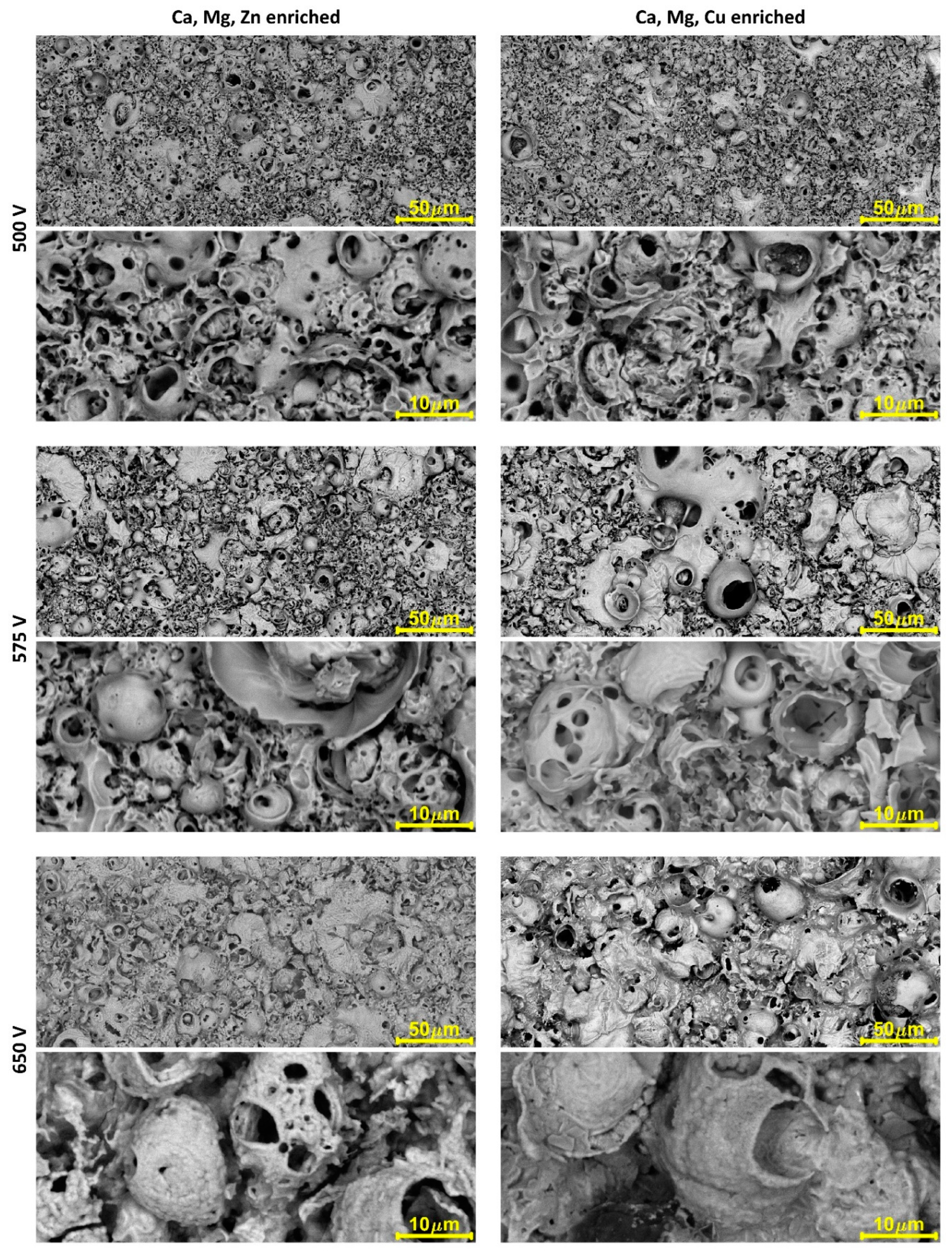
- It is possible to obtain porous calcium–magnesium–phosphate coatings enriched with copper or zinc.
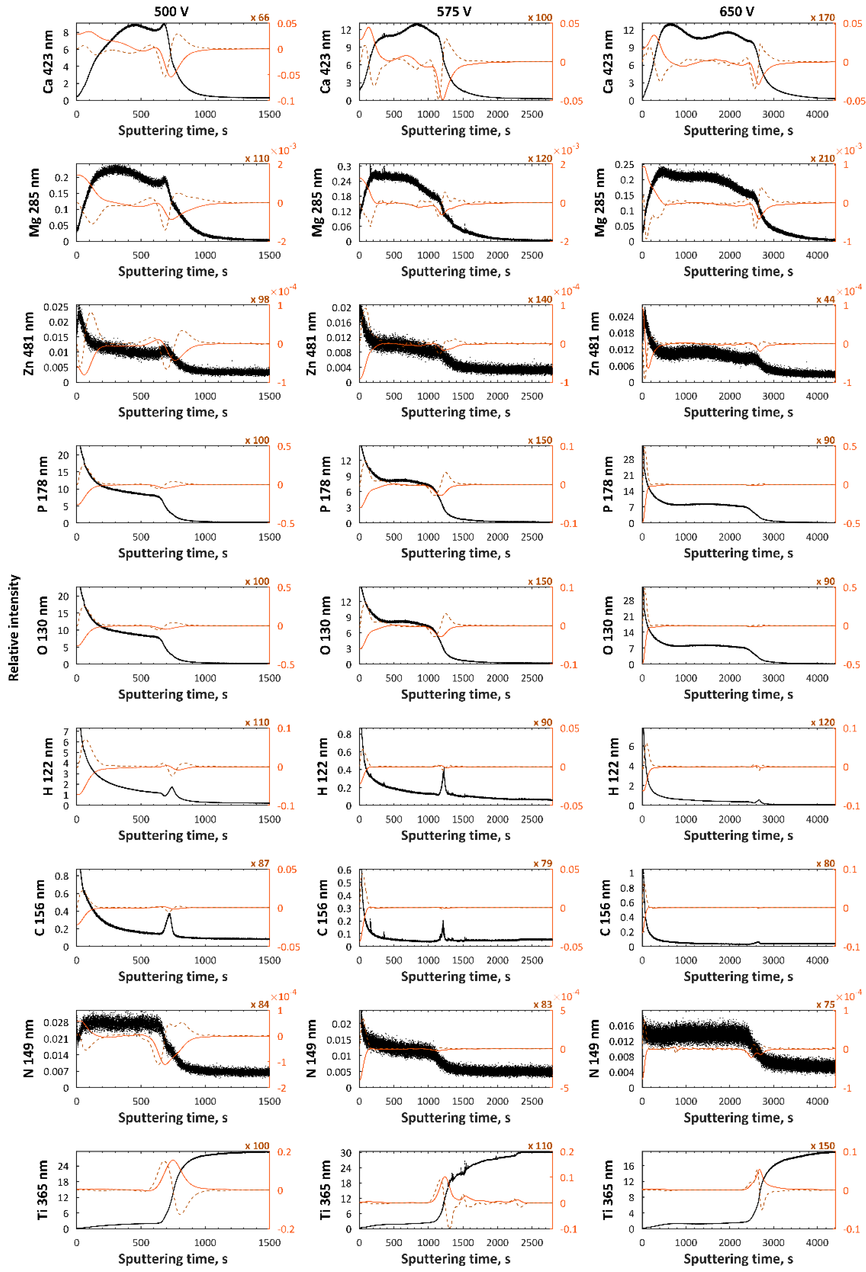
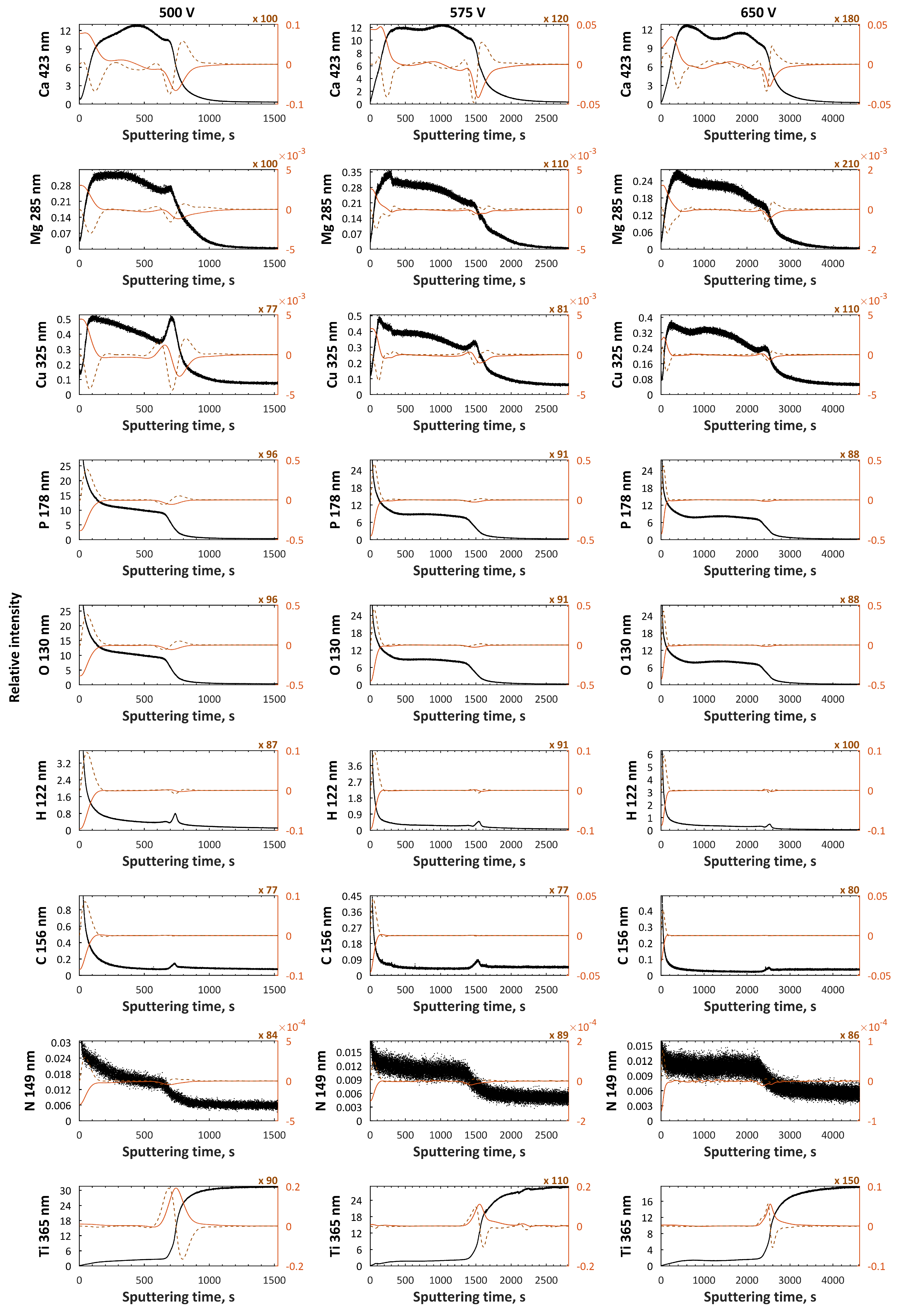
- The higher the voltage of PEO treatment, the thicker the porous coatings.
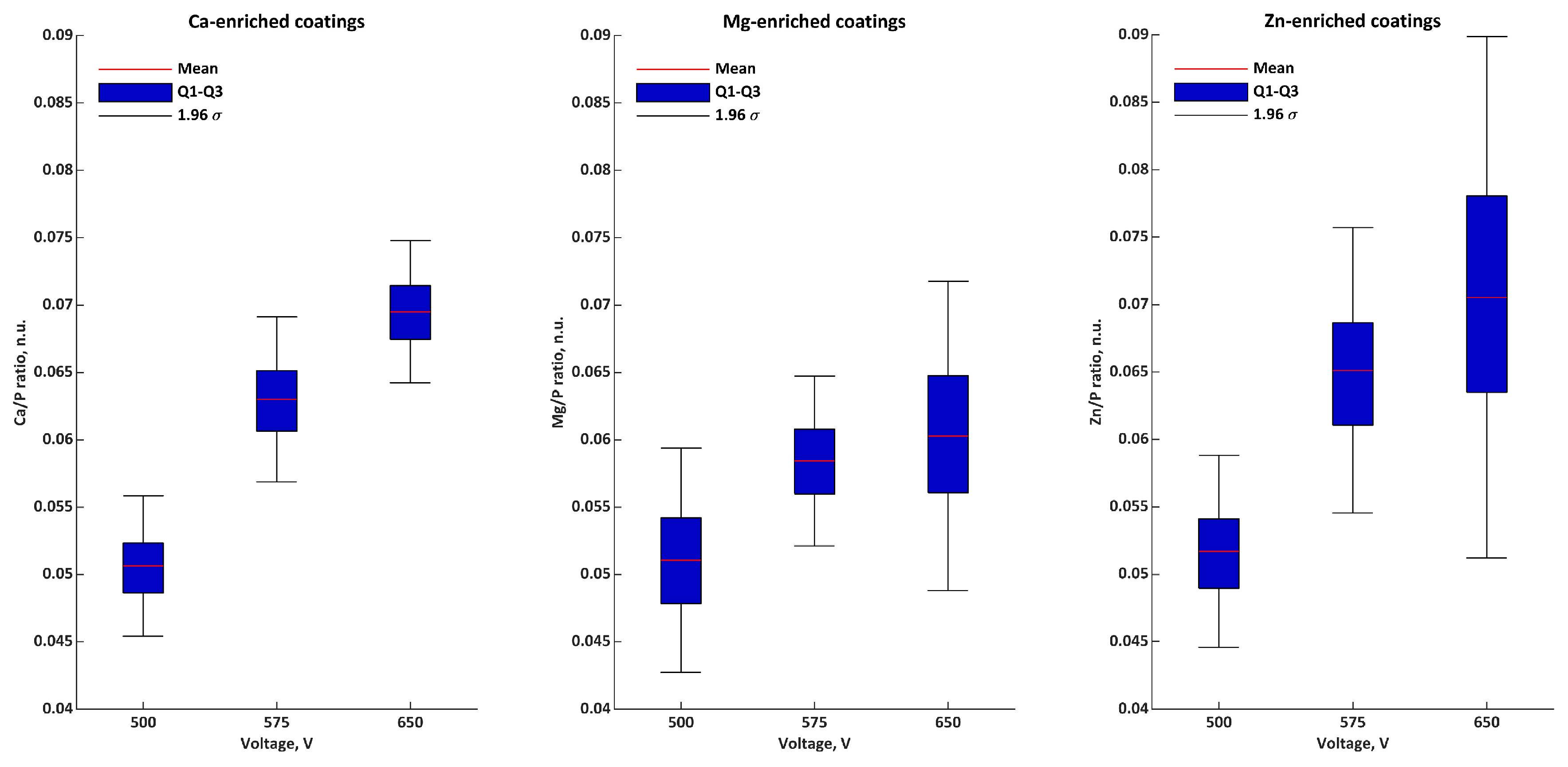
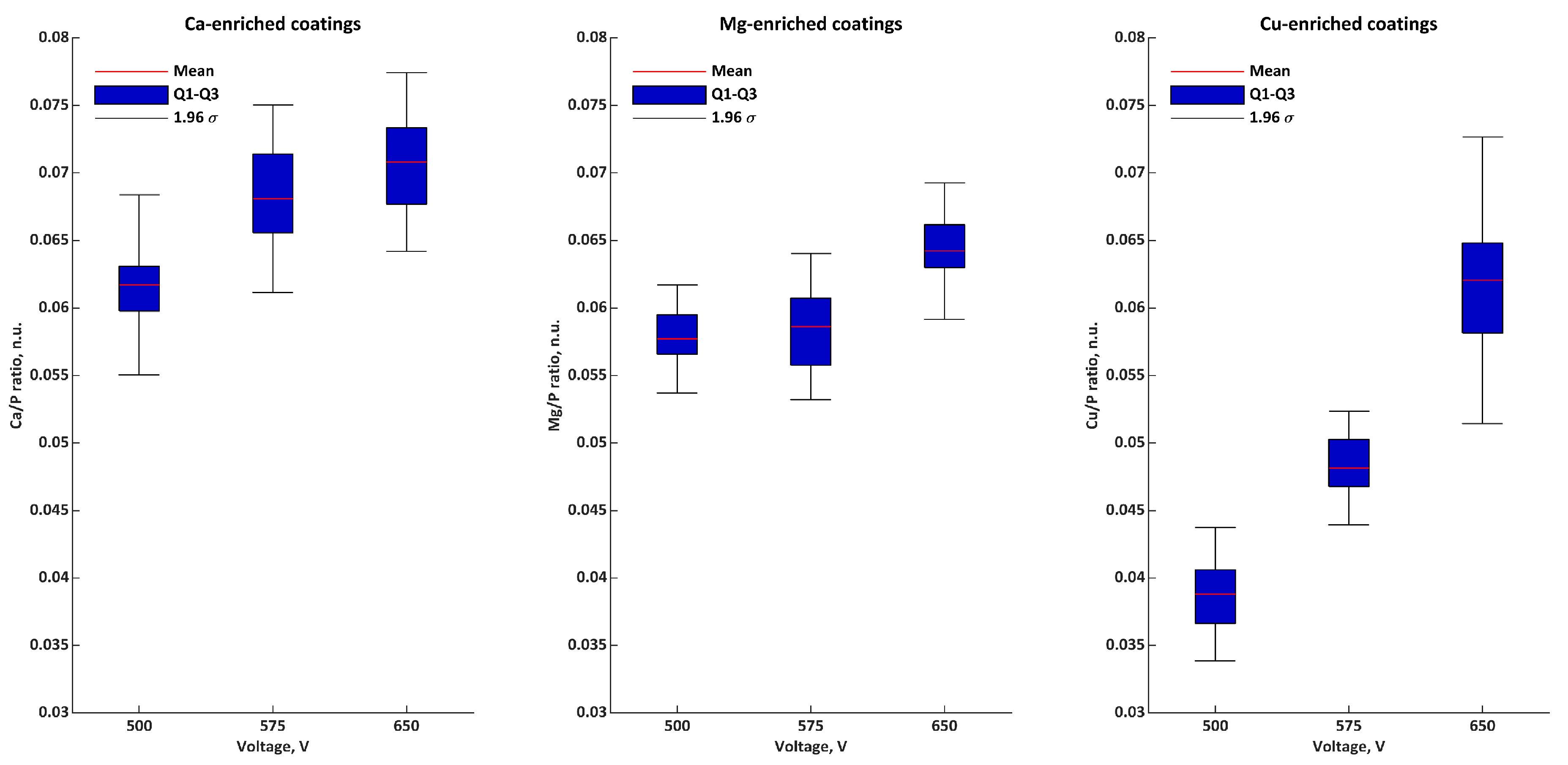
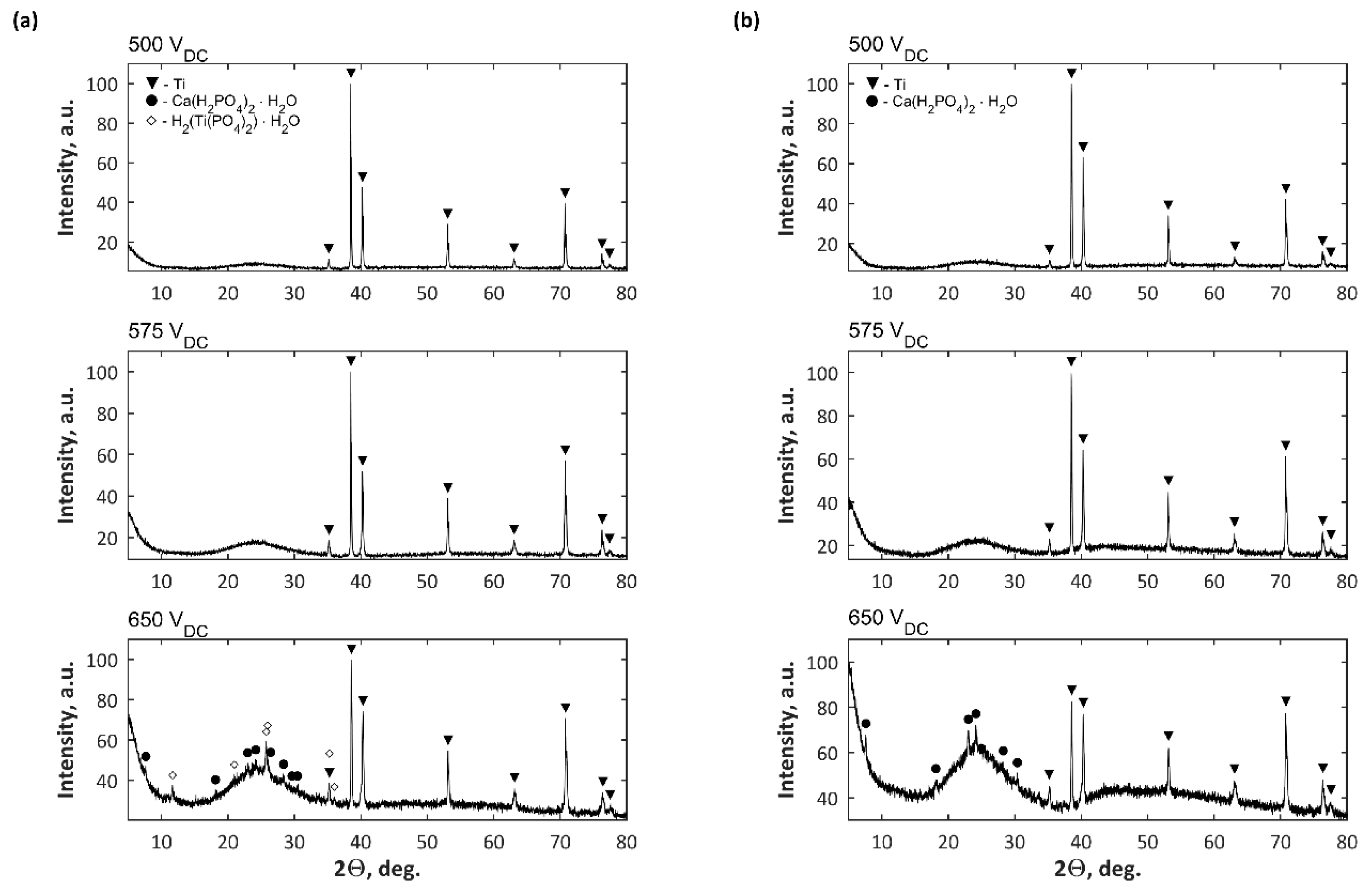
- The higher the voltage of PEO treatment, the higher the amount of built-in elements coming from the electrolyte and more amorphous phase in coatings.
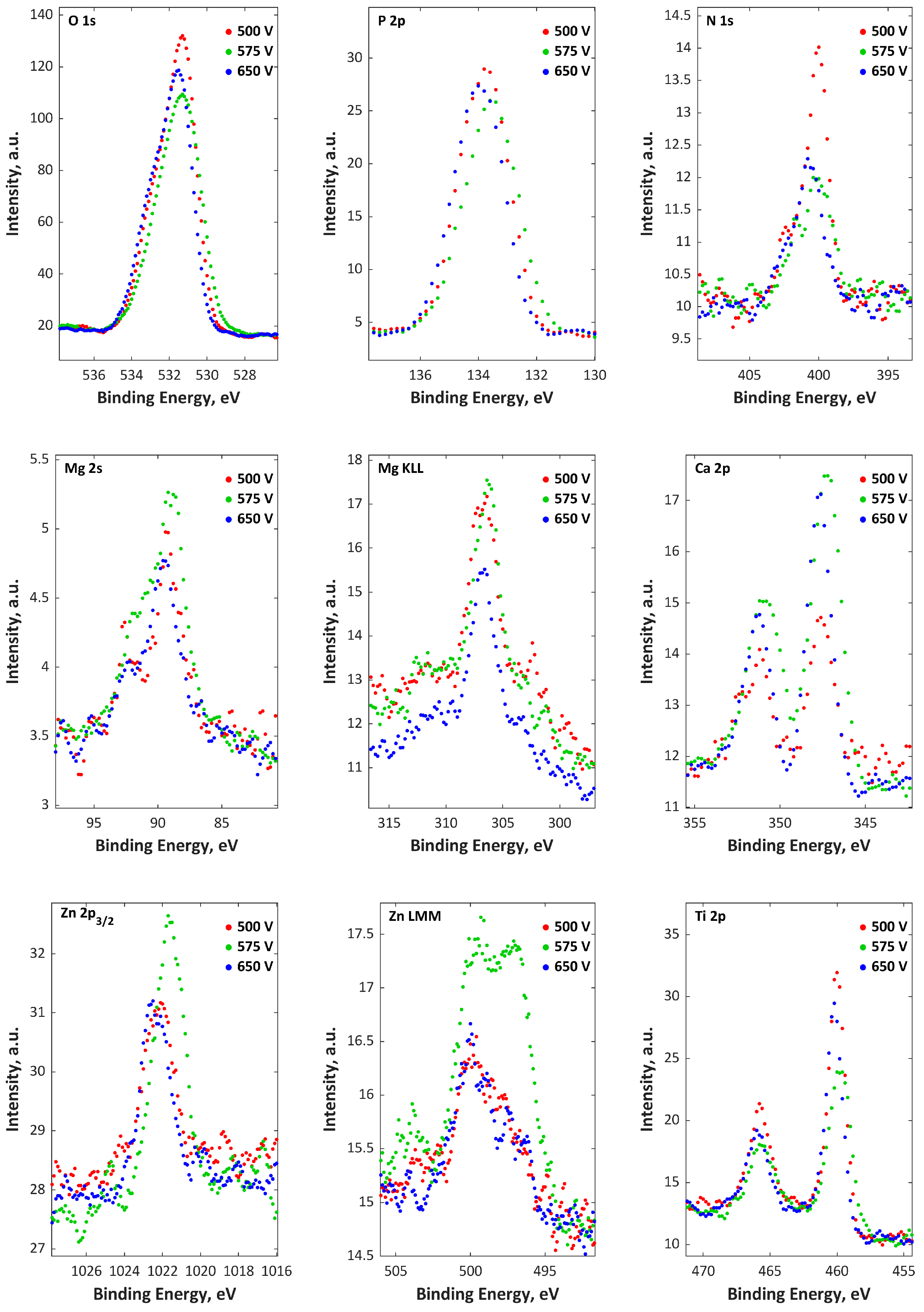
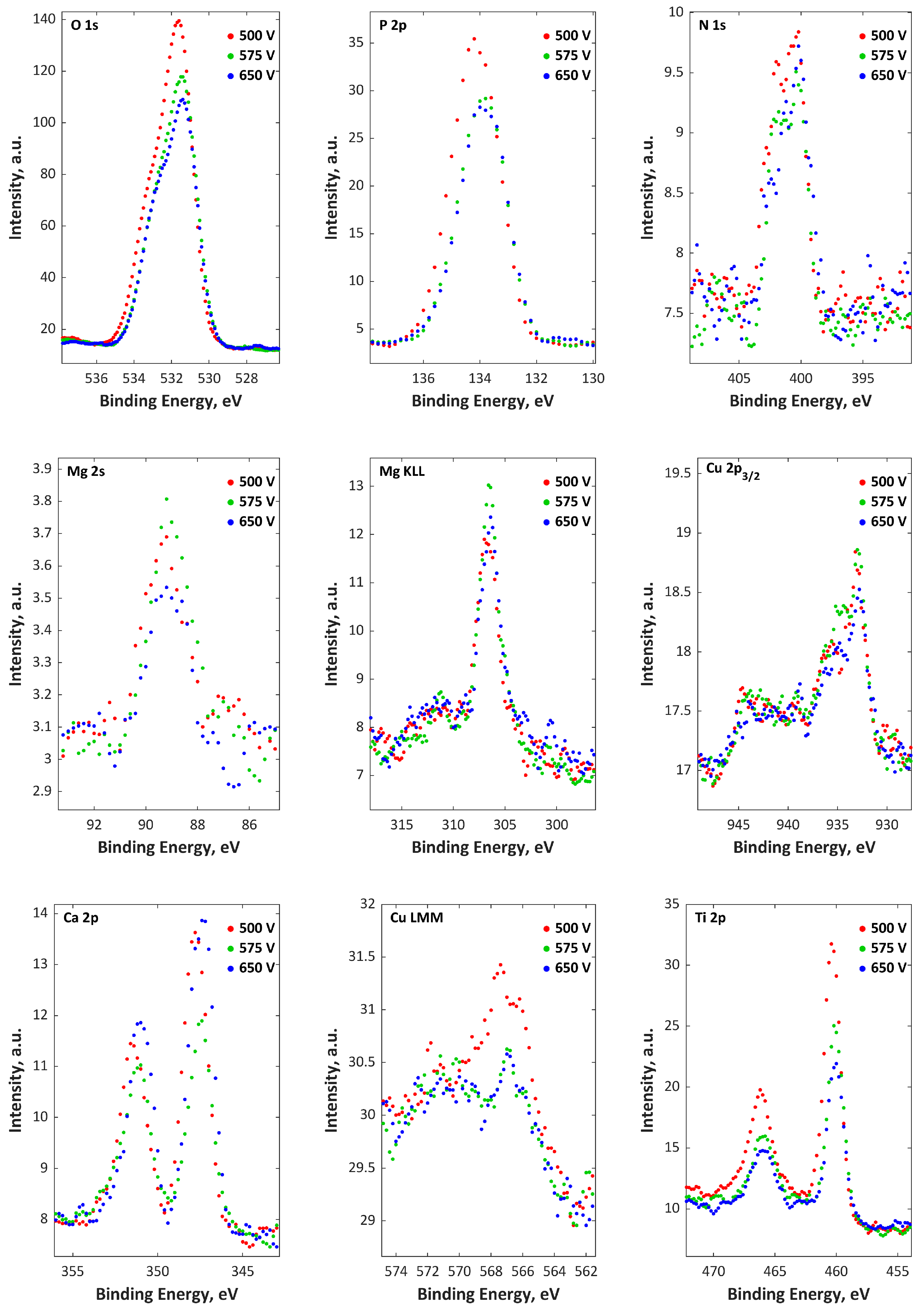
- The top 10 nm layer of the studied coatings consist mainly of Ti4+, Ca2+, Mg2+ and PO43−, HPO42−, H2PO4.
Author Contributions
Funding
Conflicts of Interest
Nomenclature
| PEO | Plasma electrolytic oxidation |
| MAO | Micro arc oxidation |
| SEM | Scanning electron microscopy |
| EDS | Energy dispersive spectroscopy |
| GDOES | Glow discharge optical emission spectroscopy |
| XPS | X-ray photoelectron spectroscopy |
| XRD | X-ray powder diffraction |
| Mean | |
| σ | Standard deviation |
| Q1 | First quartile |
| Q2 | Second quartile (median) |
| Q3 | Third quartile |
| M | Metal (here M = Ca + Mg + Zn or M = Ca+ Mg + Cu) |
| BE | Binding energy |
| f | Frequency |
| DC | Direct current |
| AC | Alternating current |
| n.u. | no unit |
References
- Sluginov, N. On luminous phenomen, observed in liquids during electrolysis. Russ. Phys. Chem. Soc. 1880, 12, 193–203. [Google Scholar]
- Braun, F. Ueber Lichtemission an einige Electroden in Electrolyten. Annalen der Physik und Chemie 1898, 65, 361–364. [Google Scholar] [CrossRef]
- Dufford, R.T. Luminescence Associated with Electrolysis. J. Opt. Soc. Am. 1929, 18, 17–28. [Google Scholar] [CrossRef]
- McNeill, W.; Gruss, L.L. Anodic Spark Reaction Processes and Articles. U.S. Patent US3293158, 17 September 1963. [Google Scholar]
- Yerokhin, A.L.; Nie, X.; Leyland, A.; Matthews, A.; Dowey, S.J. Plasma electrolysis for surface engineering. Surf. Coat. Technol. 1999, 122, 73–93. [Google Scholar] [CrossRef]
- Yerokhin, A.; Parfenov, E.V.; Matthews, A. In situ impedance spectroscopy of the plasma electrolytic oxidation process for deposition of Ca- and P-containing coatings on Ti. Surf. Coat. Technol. 2016, 301, 54–62. [Google Scholar] [CrossRef]
- Aliasghari, S. Plasma Electrolytic Oxidation of Titanium. Ph.D. Thesis, The University of Manchester, Manchester, UK, 2014; p. 223. [Google Scholar]
- Hussein, R.O.; Northwood, D.O.; Nie, X. Coating growth behavior during the plasma electrolytic oxidation process. J. Vac. Sci. Technol. A 2010, 28, 766–773. [Google Scholar] [CrossRef]
- Hussein, R.O.; Nie, X.; Northwood, D.O. An investigation of ceramic coating growth mechanisms in plasma electrolytic oxidation (PEO) processing. Electrochim. Acta 2013, 112, 111–119. [Google Scholar] [CrossRef]
- Monfort, F.; Berkani, A.; Matykina, E.; Skeldon, P.; Thompson, G.E.; Habazaki, H.; Shimizu, K. A tracer study of oxide growth during spark anodizing of aluminum. J. Electrochem. Soc. 2005, 152, C382–C387. [Google Scholar] [CrossRef]
- Hussein, R.O.; Nie, X.; Northwood, D.O.; Yerokhin, A.; Matthews, A. Spectroscopic study of electrolytic plasma and discharging behaviour during the plasma electrolytic oxidation (PEO) process. J. Phys. D Appl. Phys. 2010, 43, 105203–105215. [Google Scholar] [CrossRef]
- Dunleavy, C.S.; Golosnoy, I.O.; Curran, J.A.; Clyne, T.W. Characterisation of discharge events during plasma electrolytic oxidation. Surf. Coat. Technol. 2009, 203, 3410–3419. [Google Scholar] [CrossRef] [Green Version]
- Yerokhin, A.L.; Snizhko, L.O.; Gurevina, N.L.; Leyland, A.; Pilkington, A.; Matthews, A. Discharge characterization in plasma electrolytic oxidation of aluminium. J. Phys. D Appl. Phys. 2003, 36, 2110–2120. [Google Scholar] [CrossRef]
- Nominé, A.; Troughton, S.C.; Nominé, A.V.; Henrion, G.; Clyne, T.W. High speed video evidence for localised discharge cascades during plasma electrolytic oxidation. Surf. Coat. Technol. 2015, 269, 125–130. [Google Scholar] [CrossRef]
- Simchen, F.; Sieber, M.; Lampke, T. Electrolyte influence on ignition of plasma electrolytic oxidation processes on light metals. Surf. Coat. Technol. 2017, 315, 205–213. [Google Scholar] [CrossRef]
- Curran, A.; Clyne, T.W. Thermo-physical properties of plasma electrolytic oxide coatings on aluminium. Surf. Coat. Technol. 2005, 199, 168–179. [Google Scholar] [CrossRef]
- Curran, J.A.; Clyne, T.W. Porosity in plasma electrolytic oxide coatings. Acta Mater. 2006, 54, 1985–1993. [Google Scholar] [CrossRef]
- Snizhko, L.O.; Yerokhin, A.L.; Gurevina, N.L.; Patalakha, V.A.; Matthews, A. Excessive oxygen evolution during plasma electrolytic oxidation of aluminium. Thin Solid Films 2007, 516, 460–464. [Google Scholar] [CrossRef]
- Martin, J.; Melhem, A.; Shchedrina, I.; Duchanoy, T.; Nominè, A.; Henrion, G.; Czerwiec, T.; Belmonte, T. Effects of electrical parameters on plasma electrolytic oxidation of aluminium. Surf. Coat. Technol. 2013, 221, 70–76. [Google Scholar] [CrossRef]
- Yerokhin, A.L.; Lyubimov, V.V.; Ashitkov, R.V. Phase formation in ceramic coatings during plasma electrolytic oxidation of aluminium alloys. Ceram. Int. 1998, 24, 1–6. [Google Scholar] [CrossRef]
- Tillous, K.; Toll-Duchanoy, T.; Bauer-Grosse, E.; Hericher, L.; Geandier, G. Microstructure and phase composition of microarc oxidation surface layers formed on aluminium and its alloys 2214-T6 and 7050-T74. Surf. Coat. Technol. 2009, 203, 2969–2973. [Google Scholar] [CrossRef]
- Liu, C.; Liu, P.; Huang, Z.; Yan, Q.; Guo, R.; Li, D.; Jiang, G.; Shen, D. The correlation between the coating structure and the corrosion behavior of the plasma electrolytic oxidation coating on aluminum. Surf. Coat. Technol. 2016, 286, 223–230. [Google Scholar] [CrossRef]
- Hariprasad, S.; Ashfaq, M.; Arunnellaiappan, T.; Harilal, M.; Rameshbabu, N. Role of electrolyte additives on in-vitro corrosion behavior of DC plasma electrolytic oxidization coatings formed on CP-Ti. Surf. Coat. Technol. 2016, 292, 20–29. [Google Scholar]
- Rokosz, K.; Hryniewicz, T.; Kacalak, W.; Tandecka, K.; Raaen, S.; Gaiaschi, S.; Chapon, P.; Malorny, W.; Matýsek, D.; Dudek, Ł.; et al. Characterization of Porous Phosphate Coatings Enriched with Calcium, Magnesium, Zinc and Copper Created on CP Titanium Grade 2 by Plasma Electrolytic Oxidation. Metals 2018, 8, 411. [Google Scholar] [CrossRef]
- Matykina, E.; Arrabal, R.; Skeldon, P.; Thompson, G.E. Investigation of the growth processes of coatings formed by AC plasma electrolytic oxidation of aluminium. Surf. Coat. Technol. 2009, 54, 6767–6778. [Google Scholar] [CrossRef]
- Matykina, E.; Arrabal, R.; Skeldon, P.; Thompson, G.E. Incorporation of zirconia nanoparticles into coatings formed on aluminium by AC plasma electrolytic oxidation. J. Appl. Electrochem. 2008, 38, 1375–1383. [Google Scholar] [CrossRef]
- Dehnavi, V.; Luan, B.L.; Liu, X.Y.; Shoesmith, D.W.; Rohani, S. Correlation between plasma electrolytic oxidation treatment stages and coating microstructure on aluminum under unipolar pulsed DC mode. Surf. Coat. Technol. 2015, 269, 91–99. [Google Scholar] [CrossRef]
- Fatkullin, A.R.; Parfenov, E.V.; Yerokhin, A.; Lazarev, D.M.; Matthews, A. Effect of positive and negative pulse voltages on surface properties and equivalent circuit of the plasma electrolytic oxidation process. Surf. Coat. Technol. 2015, 284, 427–437. [Google Scholar] [CrossRef]
- Krzakala, A.; Kazek-Kesik, A.; Simka, W. Application of plasma electrolytic oxidation to bioactive surface formation on titanium and its alloys. RSC Adv. 2013, 3, 19725–19743. [Google Scholar] [CrossRef]
- Rokosz, K.; Hryniewicz, T.; Raaen, S. Development of Plasma Electrolytic Oxidation for improved Ti6Al4V biomaterial surface properties. Int. J. Adv. Manuf. Technol. 2016, 85, 2425–2437. [Google Scholar] [CrossRef]
- Rokosz, K.; Hryniewicz, T.; Matysek, D.; Raaen, S.; Valíček, J.; Dudek, Ł.; Harničárová, M. SEM, EDS and XPS analysis of the coatings obtained on titanium after plasma electrolytic oxidation in electrolytes containing copper nitrate. Materials 2016, 9, 318. [Google Scholar] [CrossRef] [PubMed]
- Rokosz, K.; Hryniewicz, T.; Raaen, S.; Chapon, P. Development of copper-enriched porous coatings on ternary Ti-Nb-Zr alloy by Plasma Electrolytic Oxidation. Int. J. Adv. Manuf. Technol. 2017, 89, 2953–2965. [Google Scholar] [CrossRef]
- Wang, S.; Zhao, Q.; Liu, D.; Du, N. Microstructure and elevated temperature tribological behavior of TiO2/Al2O3 composite ceramic coating formed by microarc oxidation of Ti6Al4V alloy. Surf. Coat. Technol. 2015, 272, 343–349. [Google Scholar] [CrossRef]
- Ma, C.; Zhang, M.; Yuan, Y.; Jing, X.; Bai, X. Tribological behavior of plasma electrolytic oxidation coatings on the surface of Mg–8Li–1Al alloy. Tribol. Int. 2012, 47, 62–68. [Google Scholar] [CrossRef]
- Rokosz, K.; Hryniewicz, T.; Gaiaschi, S.; Chapon, P.; Raaen, S.; Pietrzak, S.; Malorny, W.; Fernandes, J.S. Characterization of Porous Phosphate Coatings Enriched with Magnesium or Zinc on CP Titanium Grade 2 under DC Plasma Electrolytic Oxidation. Metals 2018, 8, 112. [Google Scholar] [CrossRef]
- Sowa, M.; Simka, W. Effect of DC Plasma Electrolytic Oxidation on Surface Characteristics and Corrosion Resistance of Zirconium. Materials 2018, 11, 723. [Google Scholar] [CrossRef] [PubMed]
- Liu, C.; He, D.; Yan, Q.; Huang, Z.; Liu, P.; Li, D.; Jiang, G.; Ma, H.; Nash, P.; Shen, D. An investigation of the coating/substrate interface of plasma electrolytic oxidation coated aluminum. Surf. Coat. Technol. 2015, 280, 86–91. [Google Scholar] [CrossRef]
- Gu, W.; Lv, G.; Chen, H.; Chen, G.; Feng, W.; Yang, S. Characterisation of ceramic coatings produced by plasma electrolytic oxidation of aluminum alloy. Mater. Sci. Eng. A 2007, 447, 158–162. [Google Scholar] [CrossRef]
- Zhu, L.; Guo, Z.; Zhang, Y.; Li, Z.; Sui, M. A mechanism for the growth of a plasma electrolytic oxide coating on Al. Electrochim. Acta 2016, 208, 296–303. [Google Scholar] [CrossRef]
- Tillous, E.K.; Toll-Duchanoy, T.; Bauer-Grosse, E. Microstructure and 3D microtomographic characterization of porosity of MAO surface layers formed on aluminium and 2214-T6 alloy. Surf. Coat. Technol. 2009, 203, 1850–1855. [Google Scholar] [CrossRef]
- Li, Q.; Liu, C.; Yang, W.; Liang, J. Growth mechanism and adhesion of PEO coatings on 2024 Al alloy. Surf. Eng. 2017, 33, 760–766. [Google Scholar] [CrossRef]
- Wang, Z.; Wu, L.; Qi, Y.; Cai, W.; Jiang, Z. Self-lubricating Al2O3/PTFE composite coating formation on surface of aluminium alloy. Surf. Coat. Technol. 2010, 204, 3315–3318. [Google Scholar] [CrossRef]
- Li, W.; Qian, Z.; Liu, X.; Zhu, L.; Liu, H. Investigation of micro-arc oxidation coating growth patterns of aluminum alloy by two-step oxidation method. Appl. Surf. Sci. 2015, 356, 581–586. [Google Scholar] [CrossRef]
- Zhang, X.M.; Chen, D.F.; Gong, X.Z.; Yang, S.Q.; Tian, X.B. Modulation effects of K2ZrF6 additive on microstructure and heat resistance of micro-arc oxide coatings fabricated on LY12 aluminum alloy. J. Inorg. Mater. 2010, 25, 865–870. [Google Scholar] [CrossRef]
- Yang, J.; Lu, X.; Blawert, C.; Di, S.; Zheludkevich, M.L. Microstructure and corrosion behavior of Ca/P coatings prepared on magnesium by plasma electrolytic oxidation. Surf. Coat. Technol. 2017, 319, 359–369. [Google Scholar] [CrossRef]
- Lu, X.; Blawert, C.; Huang, Y.; Ovri, H.; Zheludkevich, M.L.; Kainer, K.U. Plasma electrolytic oxidation coatings on Mg alloy with addition of SiO2 particles. Electrochim. Acta 2016, 187, 20–33. [Google Scholar] [CrossRef]
- Lu, X.; Blawert, C.; Kainer, K.U.; Zheludkevich, M.L. Investigation of the formation mechanisms of plasma electrolytic oxidation coatings on Mg alloy AM50 using particles. Electrochim. Acta 2016, 196, 680–691. [Google Scholar] [CrossRef]
- Ma, H.; Li, D.; Liu, C.; Huang, Z.; He, D.; Yan, Q.; Liu, P.; Nash, P.; Shen, D.J. An investigation of (NaPO3)6 effects and mechanisms during micro-arc oxidation of AZ31 magnesium alloy. Surf. Coat. Technol. 2015, 266, 151–159. [Google Scholar] [CrossRef]
- Ezhilselvi, V.; Nithin, J.; Balaraju, J.N.; Subramanian, S. The influence of current density on the morphology and corrosion properties of MAO coatings on AZ31B magnesium alloy. Surf. Coat. Technol. 2016, 288, 221–229. [Google Scholar] [CrossRef]
- Sobrinho, P.H.; Savguira, Y.; Ni, Q.; Thorpe, S.J. Statistical analysis of the voltage-time response produced during PEO coating of AZ31B magnesium alloy. Surf. Coat. Technol. 2017, 315, 530–545. [Google Scholar] [CrossRef]
- Lu, X.; Sah, S.P.; Scharnagl, N.; Störmer, M.; Starykevich, M.; Mohedano, M.; Blawert, C.; Zheludkevich, M.L.; Kainer, K.U. Degradation behavior of PEO coating on AM50 magnesium alloy produced from electrolytes with clay particle addition. Surf. Coat. Technol. 2015, 269, 155–169. [Google Scholar] [CrossRef]
- Pezzato, L.; Brunelli, K.; Gross, S.; Magrini, M.; Dabalà, M. Effect of process parameters of plasma electrolytic oxidation on microstructure and corrosion properties of magnesium alloys. J. Appl. Electrochem. 2014, 44, 867–879. [Google Scholar] [CrossRef]
- Zhang, R.F.; Zhang, S.F.; Xiang, J.H.; Zhang, L.H.; Zhang, Y.Q.; Guo, S.B. Influence of sodium silicate concentration on properties of micro arc oxidation coatings formed on AZ91HP magnesium alloys. Surf. Coat. Technol. 2012, 206, 5072–5079. [Google Scholar] [CrossRef]
- Cao, F.H.; Lin, L.Y.; Zhang, Z.; Zhang, J.Q.; Cao, C.N. Environmental friendly plasma electrolytic oxidation of AM60 magnesium alloy and its corrosion resistance. Trans. Nonferrous Met. Soc. China 2008, 18, 240–247. [Google Scholar] [CrossRef]
- Tang, H.; Xin, T.Z.; Sun, Q.; Yi, C.G.; Jiang, Z.H.; Wang, F.P. Influence of FeSO4 concentration on thermal emissivity of coatings formed on titanium alloy by micro-arc oxidation. Appl. Surf. Sci. 2011, 257, 10839–10844. [Google Scholar] [CrossRef]
- Shokouhfar, M.; Allahkaram, S.R. Formation mechanism and surface characterization of ceramic composite coatings on pure titanium prepared by micro-arc oxidation in electrolytes containing nanoparticles. Surf. Coat. Technol. 2016, 291, 396–405. [Google Scholar] [CrossRef]
- Rokosz, K.; Hryniewicz, T.; Dudek, Ł.; Matysek, D.; Valíček, J.; Harničárová, M. SEM and EDS analysis of surface layer formed on titanium after plasma electrolytic oxidation in H3PO4 with the addition of Cu(NO3)2. J. Nanosci. Nanotechnol. 2016, 16, 7814–7817. [Google Scholar] [CrossRef]
- Liu, S.M.; Yang, X.J.; Cui, Z.D.; Zhu, S.L.; Wei, Q. One-step synthesis of petal-like apatite/titania composite coating on a titanium by micro-arc treating. Mater. Lett. 2011, 65, 1041–1044. [Google Scholar] [CrossRef]
- Yan, Y.Y.; Sun, J.F.; Han, Y.; Li, D.C.; Cui, K. Microstructure and bioactivity of Ca, P and Sr doped TiO2 coating formed on porous titanium by micro-arc oxidation. Surf. Coat. Technol. 2010, 205, 1702–1713. [Google Scholar] [CrossRef]
- Rokosz, K.; Hryniewicz, T.; Gaiaschi, S.; Chapon, P.; Raaen, S.; Pietrzak, K.; Malorny, W. Characterisation of calcium- and phosphorus-enriched porous coatings on CP Titanium Grade 2 fabricated by plasma electrolytic oxidation. Metals 2017, 7, 354. [Google Scholar] [CrossRef]
- Tang, H.; Sun, Q.; Xin, T.Z.; Yi, C.G.; Jiang, Z.H.; Wang, F.P. Influence of Co(CH3COO)2 concentration on thermal emissivity of coatings formed on titanium alloy by micro-arc oxidation. Curr. Appl. Phys. 2012, 12, 284–290. [Google Scholar] [CrossRef]
- Rudnev, V.S.; Yarovaya, T.P.; Egorkin, V.S.; Sinebryukov, S.L.; Gnedenkov, S.V. Properties of coatings formed on titanium by plasma electrolytic oxidation in a phosphate-borate electrolyte. Russ. J. Appl. Chem. 2010, 83, 664–670. [Google Scholar] [CrossRef]
- Xu, Y.J.; Yao, Z.P.; Jia, F.Z.; Wang, Y.L.; Jiang, Z.H.; Bu, H.T. Preparation of PEO ceramic coating on Ti alloy and its high temperature oxidation resistance. Curr. Appl. Phys. 2010, 10, 698–702. [Google Scholar] [CrossRef]
- Qiao, L.P.; Lou, J.; Zhang, S.F.; Qu, B.; Chang, W.H.; Zhang, R.F. The entrance mechanism of calcium and phosphorus elements into micro arc oxidation coatings developed on Ti6Al4V alloy. Surf. Coat. Technol. 2016, 285, 187–196. [Google Scholar] [CrossRef]
- Wang, Y.H.; Liu, Z.G.; Ouyang, J.H.; Wang, Y.M.; Zhou, Y. Influence of electrolyte compositions on structure and high-temperature oxidation resistance of microarc oxidation coatings formed on Ti2AlNb alloy. J. Alloys Compd. 2015, 647, 431–437. [Google Scholar] [CrossRef]
- Karbowniczek, J.; Muhaffel, F.; Cempura, G.; Cimenoglu, H.; Filemonowicz, A.C. Influence of electrolyte composition on microstructure, adhesion and bioactivity of micro-arc oxidation coatings produced on biomedical Ti6Al7Nb alloy. Surf. Coat. Technol. 2017, 321, 97–107. [Google Scholar] [CrossRef]
- Montazeri, M.; Dehghanian, C.; Shokouhfar, M.; Baradaran, A. Investigation of the voltage and time effects on the formation of hydroxyapatite-containing titania prepared by plasma electrolytic oxidation on Ti-6Al-4V alloy and its corrosion behavior. Appl. Surf. Sci. 2011, 257, 7268–7275. [Google Scholar] [CrossRef]
- Simka, W.; Sowa, M.; Socha, R.P.; Maciej, A.; Michalska, J. Anodic oxidation of zirconium in silicate solutions. Electrochim. Acta 2013, 104, 518–525. [Google Scholar] [CrossRef]
- Sowa, M.; Dercz, G.; Suchanek, K.; Simka, W. Investigation of anodic oxide coatings on zirconium after heat treatment. Appl. Surf. Sci. 2015, 346, 534–542. [Google Scholar] [CrossRef]
- Matykina, E.; Arrabal, R.; Skeldon, P.; Thompson, G.E.E.; Wang, P.; Wood, P. Plasma electrolytic oxidation of a zirconium alloy under AC conditions. Surf. Coat. Technol. 2010, 204, 2142–2151. [Google Scholar] [CrossRef]
- Cengiz, S.; Uzunoglu, A.; Stanciu, L.; Tarakci, M.; Gencer, Y. Direct fabrication of crystalline hydroxyapatite coating on zirconium by single-step plasma electrolytic oxidation process. Surf. Coat. Technol. 2016, 301, 74–79. [Google Scholar] [CrossRef]
- Fidan, S.; Muhaffel, F.; Riool, M.; Cempura, G.; de Boer, L.; Zaat, S.A.J.; Filemonowicz, A.C.; Cimenoglu, H. Fabrication of oxide layer on zirconium by micro-arc oxidation: Structural and antimicrobial characteristics. Mater. Sci. Eng. C 2017, 71, 565–569. [Google Scholar] [CrossRef] [PubMed]
- Cengiz, S.; Gencer, Y. The characterization of the oxide based coating synthesized on pure zirconium by plasma electrolytic oxidation. Surf. Coat. Technol. 2014, 242, 132–140. [Google Scholar] [CrossRef]
- Cengiz, S.; Azakli, Y.; Tarakci, M.; Stanciu, L.; Gencer, Y. Microarc oxidation discharge types and bio properties of the coating synthesized on zirconium. Mater. Sci. Eng. C 2017, 77, 374–383. [Google Scholar] [CrossRef] [PubMed]
- Ha, J.-Y.Y.; Tsutsumi, Y.; Doi, H.; Nomura, N.; Kim, K.-H.H.; Hanawa, T. Enhancement of calcium phosphate formation on zirconium by micro-arc oxidation and chemical treatments. Surf. Coat. Technol. 2011, 205, 4948–4955. [Google Scholar] [CrossRef]
- Sandhyarani, M.; Rameshbabu, N.; Venkateswarlu, K.; Rama Krishna, L. Fabrication, characterization and in-vitro evaluation of nanostructured zirconia/hydroxyapatite composite film on zirconium. Surf. Coat. Technol. 2014, 238, 58–67. [Google Scholar]
- Sandhyarani, M.; Prasadrao, T.; Rameshbabu, N. Role of electrolyte composition on structural, morphological and in-vitro biological properties of plasma electrolytic oxidation films formed on zirconium. Appl. Surf. Sci. 2014, 317, 198–209. [Google Scholar]
- Apelfeld, A.V.; Betsofen, S.Y.; Borisov, A.M.; Vladimirov, B.V.; Savushkina, S.V.; Knyazev, E.V. Stabilization of the high-temperature phases in ceramic coatings on zirconium alloy produced by plasma electrolytic oxidation. J. Phys. Conf. Ser. 2016, 748, 12019. [Google Scholar] [CrossRef] [Green Version]
- Apelfeld, A.V.; Ashmarin, A.A.; Borisov, A.M.; Vinogradov, A.V.; Savushkina, S.V.; Shmytkova, E.A. Formation of zirconia tetragonal phase by plasma electrolytic oxidation of zirconium alloy in electrolyte comprising additives of yttria nanopowder. Surf. Coat. Technol. 2017, 328, 513–517. [Google Scholar] [CrossRef]
- Sowa, M.; Simka, W. Electrochemical Impedance and Polarization Corrosion Studies of Tantalum Surface Modified by DC Plasma Electrolytic Oxidation. Materials 2018, 11, 545. [Google Scholar] [CrossRef] [PubMed]
- Sowa, M.; Woszczak, M.; Kazek-Kęsik, A.; Dercz, G.; Korotin, D.M.; Zhidkov, I.S.; Kurmaev, E.Z.; Cholakh, S.O.; Basiaga, M.; Simka, W. Influence of process parameters on plasma electrolytic surface treatment of tantalum for biomedical applications. Appl. Surf. Sci. 2017, 407, 52–63. [Google Scholar] [CrossRef]
- Rokosz, K.; Hryniewicz, T.; Chapon, P.; Raaen, S.; Ricardo Zschommler Sandim, H. XPS and GDOES characterization of porous coating enriched with copper and calcium obtained on tantalum via plasma electrolytic oxidation. J. Spectrosc. 2016, 2016, 7093071. [Google Scholar] [CrossRef]
- Fattah-alhosseini, A.; Pourmahmoud, M. Passive and semiconducting properties assessment of commercially pure tantalum in Hank’s physiological solution. J. Mater. Eng. Perform. 2018, 27, 116–123. [Google Scholar] [CrossRef]
- Sowa, M.; Worek, J.; Dercz, G.; Korotin, D.M.; Kukharenko, A.I.; Kurmaev, E.Z.; Cholakh, S.O.; Basiaga, M.; Simka, W. Surface characterisation and corrosion behaviour of niobium treated in a Ca- and P-containing solution under sparking conditions. Electrochim. Acta 2016, 198, 91–103. [Google Scholar] [CrossRef]
- Sowa, M.; Simka, W. Electrochemical behavior of plasma electrolytically oxidized niobium in simulated physiological environment. Surf. Coat. Technol. 2018, 344, 21–131. [Google Scholar] [CrossRef]
- Rokosz, K.; Hryniewicz, T. Comparative SEM and EDX analysis of surface coatings created on niobium and titanium alloys after Plasma Electrolytic Oxidation (PEO). Tehnički Vjesnik-Technical Gazette 2017, 24, 465–472. [Google Scholar]
- Gomes, M.A.B.; Onofre, S.; Juanto, S.; Bulhões, L.O.S. Anodization of niobium in sulphuric acid media. J. Appl. Electrochem. 1991, 21, 1023–1026. [Google Scholar] [CrossRef]
- Pereira, B.L.; Lepienski, C.M.; Mazzaro, I.; Kuromoto, N.K. Apatite grown in niobium by two-step plasma electrolytic oxidation. Mater. Sci. Eng. C Mater. 2017, 77, 1235–1241. [Google Scholar] [CrossRef] [PubMed]
- Stojadinović, S.; Tadić, N.; Vasilic, R. Plasma electrolytic oxidation of hafnium. J. Refract. Met. Hard Mater. 2017, 69, 153–157. [Google Scholar] [CrossRef]
- Han, Y.; Hong, S.H.; Xu, K.W. Synthesis of nanocrystalline titania films by micro-arc oxidation. Mater. Lett. 2002, 56, 744–747. [Google Scholar] [CrossRef]
- Han, Y.; Xu, K. Photoexcited formation of bone apatite-like coatings on micro-arc oxidized titanium. J. Biomed. Mater. Res. 2004, 71A, 608–614. [Google Scholar] [CrossRef] [PubMed]
- Huang, P.; Xu, K.W.; Han, Y. Preparation and apatite layer formation of plasma electrolytic oxidation film on titanium for biomedical application. Mater. Lett. 2005, 59, 185–189. [Google Scholar] [CrossRef]
- Song, W.H.; Jun, Y.K.; Han, Y.; Hong, S.H.; Kim, H.E.; Heo, S.J.; Koak, J.Y. Biomimetic apatite coatings on micro-arc oxidized titania. Biomaterials 2004, 25, 3341–3349. [Google Scholar] [CrossRef] [PubMed]
- Zhang, Y.M.; Bataillon-Linez, P.; Huang, P.; Zhao, Y.M.; Han, Y.; Traisnel, M.; Xu, K.W.; Hildebrand, H.F. Surface analyses of micro-arc oxidized and hydrothermally treated titanium and effect on osteoblast behavior. J. Biomed. Mater. Res. 2003, 68, 383–391. [Google Scholar] [CrossRef] [PubMed]
- Li, L.H.; Kong, Y.M.; Kim, H.W.; Kim, Y.W.; Kim, H.E.; Heo, S.J.; Koak, J.Y. Improved biological performance of Ti implants due to surface modification by micro-arc oxidation. Biomaterials 2004, 25, 2867–2875. [Google Scholar] [CrossRef] [PubMed]
- Lee, S.H.; Kim, H.W.; Lee, E.J.; Li, L.H.; Kim, H.E. Hydroxyapatite–TiO2 hybrid coating on Ti implants. J. Biomater. Appl. 2006, 20, 194–208. [Google Scholar] [CrossRef] [PubMed]
- Han, Y.; Hong, S.H.; Xu, K.W. Structure and in vitro bioactivity of titania-based films by micro-arc oxidation. Surf. Coat. Technol. 2003, 168, 249–258. [Google Scholar] [CrossRef]
- Teh, T.H.; Berkani, A.; Mato, S.; Skeldon, P.; Thompson, G.E.; Habazaki, H.; Shimizu, K. Initial stages of plasma electrolytic oxidation of titanium. Corros. Sci. 2003, 45, 2757–2768. [Google Scholar] [CrossRef]
- Rudnev, V.S.; Vasilyeva, M.S.; Kondrikov, N.B.; Tyrina, L.M. Plasma-electrolytic formation, composition and catalytic activity of manganese oxide containing structures on titanium. Appl. Surf. Sci. 2005, 252, 1211–1220. [Google Scholar] [CrossRef]
- Ryu, H.S.; Song, W.H.; Hong, S.H. Biomimetic apatite induction on Ca-containing titania. Curr. Appl. Phys. 2005, 5, 512–515. [Google Scholar] [CrossRef]
- Chen, J.Z.; Shi, Y.L.; Wang, L.; Yan, F.Y.; Zhang, F.Y. Preparation and properties of hydroxyapatite-containing titania coating by micro-arc oxidation. Mater. Lett. 2006, 60, 2538–2543. [Google Scholar] [CrossRef]
- Matykina, E.; Montuori, M.; Gough, J.; Monfort, F.; Berkani, A.; Skeldon, P.; Thompson, G.E.; Habazaki, H. Spark anodising of titanium for biomedical applications. Trans. IMF 2006, 84, 125–133. [Google Scholar] [CrossRef]
- Han, I.H.; Choi, J.H.; Zhao, B.H.; Baik, H.K.; Lee, I.S. Effects of electrical wave form on pore size of micro-arc oxidized TiO2 film. Key Eng. Mater. 2006, 309–311, 375–378. [Google Scholar] [CrossRef]
- Shokouhfar, M.; Dehghanian, C.; Montazeri, M.; Baradaran, A. Preparation of ceramic coating on Ti substrate by plasma electrolytic oxidation in different electrolytes and evaluation of its corrosion resistance: Part II. Appl. Surf. Sci. 2012, 258, 2416–2423. [Google Scholar] [CrossRef]
- Zhu, L.; Ye, X.; Tang, G.; Zhao, N.; Gong, Y.; Zhao, Y.; Zhao, J.; Zhang, X. Corrosion test, cell behavior test, and in vivo study of gradient TiO2 layers produced by compound electrochemical oxidation. J. Biomed. Mater. Res. A 2006, 78, 515–522. [Google Scholar] [CrossRef] [PubMed]
- Habazaki, H.; Onodera, T.; Fushimi, K.; Konno, H.; Toyotake, K. Spark anodizing of β-Ti alloy for wear-resistant coating. Surf. Coat. Technol. 2007, 201, 8730–8737. [Google Scholar] [CrossRef] [Green Version]
- Kim, M.S.; Ryu, J.J.; Sung, Y.M. One-step approach for nano-crystalline hydroxyapatite coating on titanium via micro-arc oxidation. Electrochem. Commun. 2007, 9, 1886–1891. [Google Scholar] [CrossRef]
- Ragalevičius, R.; Stalnionis, G.; Niaura, G.; Jagminas, A. Micro-arc oxidation of Ti in a solution of sulfuric acid and Ti+3 salt. Appl. Surf. Sci. 2008, 254, 1608–1613. [Google Scholar] [CrossRef]
- Zhang, W.; Du, K.; Yan, C.; Wang, F. Preparation and characterization of a novel Si-incorporated ceramic film on pure titanium by plasma electrolytic oxidation. Appl. Surf. Sci. 2008, 254, 5216–5223. [Google Scholar] [CrossRef]
- Lebukhova, N.V.; Rudnev, V.S.; Kirichenko, E.A.; Chigrin, P.G.; Lukiyanchuk, I.V.; Yarovaya, T.P. Effect of the structure of the oxidized titanium surface on the particle size and properties of the deposited copper-molybdate catalyst. Prot. Met. Phys. Chem. Surf. 2016, 52, 1024–1030. [Google Scholar] [CrossRef]
- Terleeva, O.P.; Sharkeev, Y.P.; Slonova, A.I.; Mironov, I.V.; Legostaeva, E.V.; Khlusov, I.A.; Matykina, E.; Skeldon, P.; Thompson, G.E. Effect of microplasma modes and electrolyte composition on micro-arc oxidation coatings on titanium for medical applications. Surf. Coat. Technol. 2010, 205, 1723–1729. [Google Scholar] [CrossRef]
- Wang, Y.M.; Lei, T.Q.; Jiang, B.L.; Guo, L.X. Growth, microstructure and mechanical properties of microarc oxidation coatings on titanium alloy in phosphate-containing solution. Appl. Surf. Sci. 2004, 233, 258–267. [Google Scholar] [CrossRef]
- Tang, H.; Sun, Q.; Yi, C.G.; Jiang, Z.H.; Wang, F.P. High emissivity coatings on titanium alloy prepared by micro-arc oxidation for high temperature application. J. Mater. Sci. 2012, 47, 2162–2168. [Google Scholar] [CrossRef]
- Santos, A.D.; Araujo, J.R.; Landi, S.M.; Kuznetsov, A.; Granjeiro, J.M.; Sena, L.A.D.; Achete, C.A. A study of the physical, chemical and biological properties of TiO2 coatings produced by micro-arc oxidation in a Ca-P-based electrolyte. J. Mater. Sci. Mater. Med. 2014, 25, 1769–1780. [Google Scholar] [CrossRef] [PubMed]
- Li, Q.B.; Yang, W.B.; Liu, C.C.; Wang, D.A.; Liang, J. Correlations between the growth mechanism and properties of micro-arc oxidation coatings on titanium alloy: Effects of electrolytes. Surf. Coat. Technol. 2017, 316, 162–170. [Google Scholar] [CrossRef]
- Sharifi, H.; Aliofkhazraei, M.; Darband, G.; Rouhaghdam, A.S. Characterization of PEO nanocomposite coatings on titanium formed in electrolyte containing atenolol. Surf. Coat. Technol. 2016, 304, 438–449. [Google Scholar] [CrossRef]
- Zhu, X.L.; Chen, J.; Scheideler, L.; Reichl, R.; Geis-Gerstorfer, J. Effects of topography and composition of titanium surface oxides on osteoblast responses. Biomaterials 2004, 25, 4087–4103. [Google Scholar] [CrossRef] [PubMed]
- Geetha, M.; Singh, A.K.; Asokamani, R.; Gogia, A.K. Ti based biomaterials, the ultimate choice for orthopaedic implants—A review. Prog. Mater. Sci. 2009, 54, 397–425. [Google Scholar] [CrossRef]
- Jayaraman, M.; Meyer, U.; Bühner, M.; Joos, U.; Wiesmann, H.P. Influence of titanium surfaces on attachment of osteoblast-like cells in vitro. Biomaterials 2004, 25, 625–631. [Google Scholar] [CrossRef]
- Cai, Y.L.; Zhang, J.J.; Zhang, S.; Venkatraman, S.S.; Zeng, X.T.; Du, H.J.; Mondal, D. Osteoblastic cell response on fluoridated hydroxyapatite coatings: The effect of magnesium incorporation. Biomed. Mater. 2010, 5, 054114. [Google Scholar] [CrossRef] [PubMed]
- Piocha, D.; Zima, A.; Paszkiewicz, Z.; Slosarczyk, A. Physicochemical properties of the novel biphasic hydroxyapatite–magnesium phosphate biomaterial. Acta Bioeng. Biomech. 2013, 15, 53–63. [Google Scholar]
- Grigolato, R.; Pizzi, N.; Brotto, M.C.; Corrocher, G.; Desando, G.; Grigolo, B. Magnesium-enriched hydroxyapatite as bone filler in an ameloblastoma mandibular defect. Int. J. Clin. Exp. Med. 2015, 8, 281–288. [Google Scholar] [PubMed]
- Nygren, H.; Bigdeli, N.; Ilver, L.; Malmberg, P. Mg-corrosion, hydroxyapatite, and bone healing. Biointerphases 2017, 12, 02C407. [Google Scholar] [CrossRef] [PubMed]
- Laurencin, D.; Almora-Barrios, N.; de Leeuw, N.H.; Gervais, C.; Bonhomme, C.; Mauri, F.; Chrzanowski, W.; Knowles, J.C.; Newport, R.J.; Wong, A.; et al. Magnesium incorporation into hydroxyapatite. Biomaterials 2011, 32, 1826–1837. [Google Scholar] [CrossRef] [PubMed] [Green Version]
- Farzadi, A.; Bakhshi, F.; Solati-Hashjin, M.; Asadi-Eydivand, M.; Abu Osman, A.A. Magnesium incorporated hydroxyapatite: Synthesis and structural properties characterization. Ceram. Int. 2014, 40, 6021–6029. [Google Scholar] [CrossRef]
- Hu, H.; Zhang, W.; Qiao, Y.; Jiang, X.; Liu, X.; Ding, C. Antibacterial activity and increased bone marrow stem cell functions of Zn-incorporated TiO2 coatings on titanium. Acta Biomater. 2012, 8, 904–915. [Google Scholar] [CrossRef] [PubMed]
- Zhang, X.; Wang, H.; Li, J.; He, X.; Hang, R.; Huang, X.; Tian, L.; Tang, B. Corrosion behavior of Zn-incorporated antibacterial TiO2 porous coating on titanium. Ceram. Int. 2016, 42, 17095–17100. [Google Scholar] [CrossRef]
- Zhang, L.; Gao, Q.; Han, Y. Zn and Ag co-doped anti-microbial TiO2 coatings on Ti by micro-arc oxidation. J. Mater. Sci. Technol. 2016, 32, 919–924. [Google Scholar] [CrossRef]
- Zhang, J.Y.; Ai, H.J.; Qi, M. Osteoblast growth on the surface of porous Zn-containing HA/TiO2 hybrid coatings on Ti substrate by MAO plus sol-gel methods. Surf. Coat. Technol. 2013, 228, S202–S205. [Google Scholar] [CrossRef]
- Zhao, B.H.; Zhang, W.; Wang, D.N.; Feng, W.; Liu, Y.; Lin, Z.; Du, K.Q.; Deng, C.F. Effect of Zn content on cytoactivity and bacteriostasis of micro-arc oxidation coatings on pure titanium. Surf. Coat. Technol. 2013, 228, S428–S432. [Google Scholar] [CrossRef]
- Jin, G.D.; Qin, H.; Cao, H.L.; Qian, S.; Zhao, Y.C.; Peng, X.C.; Zhang, X.L.; Liu, X.Y.; Chu, P.K. Synergistic effects of dual Zn/Ag ion implantation in osteogenic activity and antibacterial ability of titanium. Biomaterials 2014, 35, 7699–7713. [Google Scholar] [CrossRef] [PubMed]
- Huang, Y.; Zhang, X.J.; Mao, H.H.; Li, T.T.; Zhao, R.L.; Yan, Y.J.; Pang, X.F. Osteoblastic cell responses and antibacterial efficacy of Cu/Zn co-substitued hydroxyapatite coatings on pure titanium using electrodeposition method. RSC Adv. 2015, 5, 17076–17086. [Google Scholar] [CrossRef]
- Rokosz, K.; Hryniewicz, T.; Gaiaschi, S.; Chapon, P.; Raaen, S.; Malorny, W.; Matysek, W.; Pietrzak, K. Development of porous coatings enriched with magnesium and zinc obtained by DC Plasma Electrolytic Oxidation. Micromachines 2018, 9, 332. [Google Scholar] [CrossRef]
- Zhao, L.Z.; Chu, P.K.; Zhang, Y.M.; Wu, Z.F. Antibacterial coatings on titanium implants. J. Biomed. Mater. Res. Part B 2009, 91, 470–480. [Google Scholar] [CrossRef] [PubMed]
- Zhu, W.; Zhang, Z.; Gu, B.; Sun, J.; Zhu, L. Biological activity and antibacterial property of nano-structured TiO2 coating incorporated with Cu prepared by micro-arc oxidation. J. Mater. Sci. Technol. 2013, 29, 237–244. [Google Scholar] [CrossRef]
- Zhang, L.; Guo, J.; Huang, X.; Zhang, Y.; Han, Y. The dual function of Cu-doped TiO2 coatings on titanium for application in percutaneous implants. J. Mater. Chem. B 2016, 4, 3788–3800. [Google Scholar] [CrossRef]
- Moulder, J.F.; Stickle, W.F.; Sobol, P.E.; Bomben, K.D. Handbook of X-ray Photoelectron Spectroscopy; Perkin-Elmer Corporation: Eden Prairie, MN, USA, 1992. [Google Scholar]
- Wagner, C.D.; Naumkin, A.V.; Kraut-Vass, A.; Allison, J.W.; Powell, C.J.; Rumble, J.R., Jr. NIST Standard Reference Database 20, Version 3.4. 2003. Available online: http://srdata.nist.gov/xps (accessed on 1 July 2018).
- Casa Software Ltd. CasaXPS: Processing Software for XPS, AES, SIMS and More. 2009. Available online: http://www.casaxps.com (accessed on 1 July 2018).
- Gaiaschi, S.; Richard, S.; Chapon, P.; Acher, O. Real-time measurement in glow discharge optical emission spectrometry via differential interferometric profiling. J. Anal. Atom. Spectrom. 2017, 32, 1798–1804. [Google Scholar] [CrossRef]
- Pulsed RF Glow Discharge Optical Emission Spectrometry—Ultra Fast Elemental Depth Profiling, HORIBA Scientific, Printed in France—©HORIBA Jobin Yvon. 2014, p. 7. Available online: http://www.horiba.com/scientific/products/atomic-emission-spectroscopy/glow-discharge/ (accessed on 1 July 2018).


| Electrolytes | Voltage Current Density | Ref. |
|---|---|---|
| H2O, NaAlO2, Na3PO4·12H2O, KOH, NaCl | 100–900 mA·cm−2 (f = 50 Hz) | [7] |
| H2O, Na3PO4·12H2O, KOH, Na2SO4, (HOCH2)3CNH2, (NH4)2HPO4, C2H7NO2 | 70 mA·cm−2 (f = 50 Hz) | [23] |
| H3PO4, Ca(NO3)2·4H2O, Mg(NO3)2·6H2O, Cu(NO3)2·3H2O, Zn(NO3)2·6H2O | 500, 575, 650 V | [24] |
| H3PO4, Cu(NO3)2·3H2O | 450 V | [32] |
| H2O, Na2SiO3, (NaPO3)6, NaAlO2 microparticle | 80 mA·cm−2 (f = 300 Hz) | [33] |
| H3PO4, Mg(NO3)2·6H2O, Zn(NO3)2·6H2O | 500–650 V | [35] |
| H2O, Na3PO4, FeSO4 | 350 V (f = 100 Hz) | [55] |
| H2O, NaAlO2, KOH | 400 V (f = 2000 Hz) | [56] |
| H2O, (CH3COO)2Ca·H2O, NaH2PO4·2H2O | 300, 390 V (f = 900 Hz) | [58] |
| H2O, Ca(CH3COO)2,Sr(CH3COO)2 | 400, 450 V (f = 100 Hz) | [59] |
| H3PO4, Ca(NO3)2·4H2O | 500, 575, 650 V | [60] |
| H2O, Na3PO4, Co(CH3COO)2 | 350 V (f = 100 Hz) | [61] |
| H2O, Na3PO4·12H2O, Na2B4O7·10H2O, Na3WO4·2H2O | 50 mA·cm−2 | [62] |
| H2O, Na2SiO3, Na2CO3, NaOH | 12 mA·cm−2 (f = 100 Hz) | [63] |
| H2O, C6H18O24P6, KOH, EDTA-Na2, Ca(CH3COO)2 | 20, 50, 80 V | [64] |
| H2O, NaAlO2, Na2SiO3, (NaPO3)6 | 550 V | [65] |
| H2O, Na2HPO4, C4H6O4Ca·H2O | +400 V/−80 V (f = 250 Hz) | [66] |
| H2O, C3H9O6P, C4H6O4Ca·H2O | +400 V/−80 V (f = 250 Hz) | [66] |
| H2O, Na2HPO4, C3H7CaO6P·H2O | +400 V/−80 V (f = 250 Hz) | [66] |
| H2O, (CH3COO)2Ca·H2O, NaH2PO4·H2O | 350–500 V (f = 1000 Hz) | [67] |
| H2O, Ca(CH3COO)2·H2O | 300 V (f = 1000 Hz) | [90] |
| H2O, (CH1COO)2Ca, C3H7Na2O6P | 250–400 V (f = 100 Hz) | [91] |
| H2O, (CH3COO)2Ca·H2O, C3H7Na2O6P·5H2O | 450 V (f = 100 Hz) | [92] |
| H2O, (CH3COO)2Ca·H2O, C3H7Na2O6P·5H2O | 250–500 V (f = 1000 Hz) | [93,94] |
| H2O, Ca(CH3COO)2·H2O, CaC3H7O6P | 190–600 V (f = 660 Hz) | [95,96] |
| H2O, (CH3COO)2Ca·H2O, C3H7Na2O6P·5H2O | 200–500 V (f = 900 Hz) | [97] |
| H2O, Na4P2O7·10H2O and KOH, NaAlO2 | 0–300 V | [98] |
| Na2B4O7·10H2O, (CH3COO)2Mn·4H2O | 450–500 V | [99] |
| H2O, (CH3COO)2Ca·H2O | 230 V | [100] |
| H2O, (CH3COO)2Ca·H2O, NaH2PO4·2H2O | 260–420 V | [101] |
| H2O, CaHPO4, Ca(H2PO4)2, Na6P6O18, Ca(CH3COO)2 | 20, 100 mA·cm−2 | [102] |
| H2O, KOH | 290 V (f = 100–200 Hz) | [103] |
| H2O, KOH | 350 V (f = 1000 Hz) | [104] |
| H2O, (NaPO3)6, NaF, NaAlO2 | 150–200 V | [105] |
| H2O, K2Al2O4, Na3PO4, NaOH | 400 V | [106] |
| H2O, CaCl2 and KH2PO4 | 320–340 V | [107] |
| H2O, H2SO4 and Ti2(SO4)3 | 1100 V | [108] |
| H2O, Na2(EDTA), CaO, Ca(H2PO4)2, Na2SiO3·H2O | 350 V (f = 200 Hz) | [109] |
| H2O, Na2SiO3, NaOH | 280 V | [110] |
| H2O, CaO, Na6P6O18, Na2H2EDTA⋅5.5H2O, KOH | AC 0.5–2 mA·cm−2 | [111] |
| 2O, (NaPO3)6, NaF, NaAlO2 | 60 mA·cm−2 (f = 100, 600 Hz) | [112] |
| H2O, Na3PO4, FeSO4, Co(CH3COO)2, Ni(CH3COO)2, K2ZrF6 | 350 V (f = 100 Hz) | [113] |
| H2O, Ca(CH3COO)2·H2O, C3H7Na2O6P | 150 V | [114] |
| H2O, Na2SiO3·9H2O, Na3PO4·12H2O, Na2SiO3·9H2O, Na3PO4·12H2O | 80 mA·cm−2 (f = 150 Hz) | [115] |
| H2O, Na3PO4·12H2O, α-Al2O3 nanoparticles | 20 mA·cm−2 | [116] |
| Sample Name | Voltage | Electrolyte Type | Electrolyte Composition | |
|---|---|---|---|---|
| Salts | Salt Concentrations (g/L) | |||
| Ti_CaMgZn_500V | 500 V | Electrolyte 1 | Ca(NO3)2·4H2O and Mg(NO3)2·6H2O & Zn(NO3)2·6H2O | 166.7 + 166.7 + 166.7 |
| Ti_CaMgZn_575V | 575 V | |||
| Ti_CaMgZn_650V | 650 V | |||
| Ti_CaMgCu_500V | 500 V | Electrolyte 2 | Ca(NO3)2·4H2O and Mg(NO3)2·6H2O & Cu(NO3)2·3H2O | 166.7 + 166.7 + 166.7 |
| Ti_CaMgCu_575V | 575 V | |||
| Ti_CaMgCu_650V | 650 V | |||
| Technique | Equipment | Manufacturer |
|---|---|---|
| SEM | Quanta 650 FEI | Field Electron and Iron Company, Hillsboro, OR, USA |
| EDS | Noran System Six | EDS, Silicon Drift Detectors: Keith Thompson, Thermo Fisher Scientific, Madison, WI, USA |
| XPS | SCIENCE SES 2002 | Scienta AB, Scienta Omicron, Uppsala, Sweden |
| GDOES | GD Profiler 2 | HORIBA Scientific, Palaiseau, France |
| XRD | Bruker-AXS D8 Advance | Bruker Corporation, Billerica, MA, USA |
| Ratios | Voltage | σ | Q1 | Q2 | Q3 | |
|---|---|---|---|---|---|---|
| Ca/P n.u. | 500 V | 0.051 | 0.003 | 0.050 | 0.052 | 0.052 |
| 575 V | 0.063 | 0.003 | 0.062 | 0.064 | 0.065 | |
| 650 V | 0.069 | 0.003 | 0.068 | 0.071 | 0.071 | |
| Mg/P n.u. | 500 V | 0.051 | 0.004 | 0.049 | 0.051 | 0.053 |
| 575 V | 0.058 | 0.003 | 0.057 | 0.060 | 0.060 | |
| 650 V | 0.060 | 0.006 | 0.057 | 0.063 | 0.063 | |
| Zn/P n.u. | 500 V | 0.052 | 0.004 | 0.050 | 0.053 | 0.054 |
| 575 V | 0.065 | 0.005 | 0.063 | 0.068 | 0.068 | |
| 650 V | 0.071 | 0.010 | 0.065 | 0.075 | 0.075 | |
| M/P n.u. | 500 V | 0.153 | 0.008 | 0.149 | 0.151 | 0.157 |
| 575 V | 0.187 | 0.006 | 0.184 | 0.188 | 0.190 | |
| 650 V | 0.200 | 0.015 | 0.192 | 0.195 | 0.206 |
| Ratios | Voltage | σ | Q1 | Q2 | Q3 | |
|---|---|---|---|---|---|---|
| Ca/P n.u. | 500 V | 0.062 | 0.003 | 0.060 | 0.061 | 0.062 |
| 575 V | 0.068 | 0.004 | 0.066 | 0.068 | 0.071 | |
| 650 V | 0.071 | 0.003 | 0.068 | 0.072 | 0.073 | |
| Mg/P n.u. | 500 V | 0.058 | 0.002 | 0.057 | 0.057 | 0.059 |
| 575 V | 0.059 | 0.003 | 0.056 | 0.060 | 0.061 | |
| 650 V | 0.064 | 0.003 | 0.064 | 0.064 | 0.066 | |
| Cu/P n.u. | 500 V | 0.039 | 0.003 | 0.037 | 0.040 | 0.040 |
| 575 V | 0.048 | 0.002 | 0.047 | 0.048 | 0.050 | |
| 650 V | 0.062 | 0.005 | 0.059 | 0.061 | 0.063 | |
| M/P n.u. | 500 V | 0.158 | 0.006 | 0.156 | 0.156 | 0.159 |
| 575 V | 0.175 | 0.006 | 0.172 | 0.176 | 0.177 | |
| 650 V | 0.197 | 0.004 | 0.195 | 0.196 | 0.197 |
© 2018 by the authors. Licensee MDPI, Basel, Switzerland. This article is an open access article distributed under the terms and conditions of the Creative Commons Attribution (CC BY) license (http://creativecommons.org/licenses/by/4.0/).
Share and Cite
Rokosz, K.; Hryniewicz, T.; Gaiaschi, S.; Chapon, P.; Raaen, S.; Matýsek, D.; Dudek, Ł.; Pietrzak, K. Novel Porous Phosphorus–Calcium–Magnesium Coatings on Titanium with Copper or Zinc Obtained by DC Plasma Electrolytic Oxidation: Fabrication and Characterization. Materials 2018, 11, 1680. https://doi.org/10.3390/ma11091680
Rokosz K, Hryniewicz T, Gaiaschi S, Chapon P, Raaen S, Matýsek D, Dudek Ł, Pietrzak K. Novel Porous Phosphorus–Calcium–Magnesium Coatings on Titanium with Copper or Zinc Obtained by DC Plasma Electrolytic Oxidation: Fabrication and Characterization. Materials. 2018; 11(9):1680. https://doi.org/10.3390/ma11091680
Chicago/Turabian StyleRokosz, Krzysztof, Tadeusz Hryniewicz, Sofia Gaiaschi, Patrick Chapon, Steinar Raaen, Dalibor Matýsek, Łukasz Dudek, and Kornel Pietrzak. 2018. "Novel Porous Phosphorus–Calcium–Magnesium Coatings on Titanium with Copper or Zinc Obtained by DC Plasma Electrolytic Oxidation: Fabrication and Characterization" Materials 11, no. 9: 1680. https://doi.org/10.3390/ma11091680