A Review of Carbon Nanomaterials’ Synthesis via the Chemical Vapor Deposition (CVD) Method


1
Qatar Environment and Energy Research Institute (QEERI), Qatar Foundation, P.O. Box 5825, Doha, Qatar
2
College of Science and Engineering, Hamad Bin Khalifa University (HBKU), Qatar Foundation, P.O. Box 5825, Doha, Qatar
3
Center for Environment & Water (CEW), Research Institute, King Fahd University of Petroleum and Minerals (KFUPM), Dhahran 31261, Saudi Arabia
4
Division of Sustainable Development, College of Science and Engineering, Hamad Bin Khalifa University(HBKU), Qatar Foundation, P.O. Box 5825, Doha, Qatar
*
Authors to whom correspondence should be addressed.
Materials 2018, 11(5), 822; https://doi.org/10.3390/ma11050822
Submission received: 17 December 2017
/
Revised: 10 February 2018
/
Accepted: 11 February 2018
/
Published: 17 May 2018
(This article belongs to the Section Carbon Materials)
Abstract
:Carbon nanomaterials have been extensively used in many applications owing to their unique thermal, electrical and mechanical properties. One of the prime challenges is the production of these nanomaterials on a large scale. This review paper summarizes the synthesis of various carbon nanomaterials via the chemical vapor deposition (CVD) method. These carbon nanomaterials include fullerenes, carbon nanotubes (CNTs), carbon nanofibers (CNFs), graphene, carbide-derived carbon (CDC), carbon nano-onion (CNO) and MXenes. Furthermore, current challenges in the synthesis and application of these nanomaterials are highlighted with suggested areas for future research.
1. Introduction
Materials can be referred to as nano-scaled when their size range from approximately 1 nm to 100 nm [1]. Nanomaterials have gained considerable attention in various fields owing to their tremendous properties [2,3]. Carbon, one of the most abundant materials found on earth, can be found in nature in its elemental form as graphite, diamond and coal [4,5]. The carbon nanomaterials with their excellent properties are ideal candidates for advanced applications in the area of electronics, membranes, wastewater treatment, batteries, capacitors, heterogeneous catalysis, as well as biological and medical sciences [6,7,8,9,10,11,12,13,14,15,16,17].
It is well known that the morphologies, sizes and phases of nanomaterials have great influence on their properties and potential applications [18]. Therefore, the synthesis of nanostructured materials with desired properties has recently received much attention [19,20,21]. Carbon can be found in several different hybridization states, each having unique properties as shown in Figure 1 [4]. In fact, the electrical, thermal, mechanical and chemical properties of the different allotrope forms are directly correlated to their hybridization state and structure, opening up the possibility to use the same material for a wide range of applications [4].
Various techniques have been reported in the literature for the synthesis of 0D, 1D, 2D, and 3D carbon nanomaterials. The most common techniques are laser ablation [22,23,24,25], arc-discharge [25,26] and chemical vapor deposition (CVD) [27,28]. CVD is the most commonly employed thin-film deposition technique used to synthesize nanomaterials. Therefore, this review paper will be mainly focused on the synthesis of novel materials via the CVD technique.
This review paper summarizes the synthesis of carbon nanomaterials such as fullerenes, carbon nanotubes (CNTs), carbon nanofibers (CNFs), graphene, carbide-derived carbon (CDC), carbon nano-onion (CNO) and MXene via the CVD method.
2. Synthesis of Carbon Nanomaterials
2.1. Fullerenes
Fullerene is an allotrope of carbon which has a hollow structure that takes the shape of the sphere, tube, ellipsoid in addition to some other structures [29]. By definition, a fullerene is a closed cage molecule containing only hexagonal and pentagonal faces [30]. Spherical fullerenes look like balls and that’s why they are sometimes referred to as Bucky-balls. On the other hand, bucky-tube is the name used to denote cylindrically shaped fullerene or carbon nanotubes. Structure-wise, all fullerenes are similar to graphite which consists of arranged graphene sheets (composed of linked hexagonal rings) [29]. Additionally, fullerene could also consist of pentagonal or heptagonal rings. Buckminsterfullerene (C60), was the first Fullerene to be discovered in 1985 by Richard Smalley et al. [31]. In fact, this structure had been identified by Sumio Iijima in 1980 using an electron microscope image [32]. The identified structure was the core of the bucky onion or CNOs [32]. Fullerene has widened the family of carbon allotropes which includes CNTs, graphene, charcoal, soot, CNOs, etc. (as shown in Figure 2).
2.1.1. Synthesis of Fullerenes via Chemical Vapor Deposition (CVD)
Fullerenes can be synthesized using several techniques; the most commonly used ones are laser ablation [25], arc vaporization of graphite [25], and CVD methods [34,35]. Fullerenes are traditionally produced by the CVD method, combustion processes and arc-discharge vaporization of graphite. However, these methods are not very efficient, and continued refinements and improvements in this area are needed. Therefore, developing new, efficient methods for the synthesis of fullerene with high yields and purity is still a challenge for researchers. The CVD method for the production of fullerenes, however, has the advantage that lower temperature is required as compared to laser vaporization and arc discharge. Kleckley et al. [34] presented two methods for the synthesis of fullerene that are hot-filament CVD and microwave-enhanced CVD methods.
Hot-Filament CVD
A schematic diagram of the hot-filament CVD is shown in Figure 3 [34]. The chamber is constructed of stainless steel with a filament made of tungsten wire. The filament hangs vertically, with the lower terminal attached to a braided copper wire and the upper terminal fixed. A stainless steel substrate holder is used for thin-film deposition. The filament temperatures are typically from 2000 °C to 2200 °C and the filament currents are between 50 A and 60 A. The typical substrate temperatures are between 950 °C and 1000 °C for the growth of CVD diamond-thin films. The feed gases are 99.999% pure hydrogen and 99.8% pure methane. The pressure of the chamber is controlled in the range of 30–100 Torr.
Microwave-Enhanced CVD
Microwave CVD apparatus is presented in Figure 4 [34]. A quartz tube was used as a reaction chamber. A 100 W 2.45 GHz generator was used as the excitation source, which was connected to an Evenson-type cavity. The feed gases we used included Ar, H2 and C2H2. Typical pressures were between 1 Torr and 10 Torr. It was found that at p > 25 Torr, a conducting film was building up inside the quartz tube, which limited the deposition process to only a few minutes. At lower pressure, it was observed that the plasma region was much more extended, and it resembled a glow discharge plasma. At p < 10 Torr, a yellowish film was deposited on the inside wall of the quartz tube. The film color changed to dark brown after being exposed to the plasma for 30 min.
2.2. Carbon Nanotubes (CNTs)
Carbon exist in many molecular forms, known as allotropes of carbon. Carbon nanotubes (CNTs) are allotropes of carbon that are composed of cylindrical graphite sheets rolled up in a tube-like structure [36]. CNTs that are composed of a single graphene sheet are termed as single-walled carbon nanotubes (SWCNTs). Conversely, multilayers of graphene sheets are known as multi-walled carbon nanotubes (MWCNTs). The multi-walled nanotubes (MWCNTs) and single-walled carbon nanotubes (SWCNTs) are depicted in Figure 5 [37]. Figure 6 depicts several SWCNT structures based on the way graphene sheets are rolled [38].
Chiral indices (n,m) is an index used to identify the structure of the CNTs according to the orientation of the tube axis with respect to the hexagonal lattice. The origin of the zigzag (n = 0) and armchair (n = m) nanotubes’ structure was adopted from the geometric arrangements of carbon atoms at the cylinder’s seam. Nanotube structures with a characteristic two enantiomers with right and hand side helicity (n ≠ m) are called chiral [38].
In 1991, Sumio Ijima at the NEC Laboratory in Tsukuba, Japan, discovered CNTs using the arc-discharge technique. These CNTs were then characterized using a high-resolution transmission electron microscope (HRTEM) [39]. Chemical bonding in nanotubes is composed entirely of sp2 bonds, which are stronger than the sp3 bonds found in alkanes and provide nanotubes with unique strength [40]. Interestingly, CNTs have much higher length-to-diameter ratio than other existing materials (i.e., up to 132,000,000:1) [40].
Due to their unique hexagonal structure, CNTs possess some extraordinary properties (electrical, mechanical and thermal) which make them versatile in many applications in various fields [41,42]. Being part of the fullerene family, the name of CNTs was derived from the long hollow hexagonal cylindrical structure which has one-atom thick walls made from carbon sheets referred to as “graphene”. The respective sheets are then rolled at specific chiral angles. Eventually, the properties of the rolled CNTs are decided by the radius and the rolling angle. Normally, CNT cylinders are topped with a fullerene-type molecule [43]. In fact, there are two types of CNTs i.e., single-walled nanotubes (SWCNTs) and multi-walled nanotubes (MWCNTs) as shown in Figure 5. Each of these two types of CNTs aligns themselves as ropes while being attracted to each other through van der Waals forces [44].
A single graphene sheet has rolled up to form a cylindrical tube (SWCNT) with a diameter ranging between 0.4 nm and 3 nm [45]. On the other hand, MWCNTs can be defined as concentric cylinders made from graphene sheets with diameters up to 100 nm [46]. The structure of SWNTs can be determined by wrapping the constituting graphene sheet into a cylinder. As shown in Figure 6, the way this graphene sheet is wrapped is expressed by the indices n and m (or n,m). In this way, the indices n and m signify the number of unit vectors along the two directions in the honeycomb crystal lattice of graphene. When index m = 0, the structure of the nanotube is referred to zigzag; however, when n = m, the structure of the nanotube is called armchair. Otherwise, the nanotubes’ structure is referred to as chiral [47].
2.2.1. Synthesis of CNTs
The most common methods for CNT production are CVD [47,48,49], laser ablation [24] and electric arc discharge [50,51]. However, CVD has proven itself as a favored method for the mass production of CNTs [52,53]. Various CVD techniques employed for the production of CNTs include hot-wire (HWCVD), hot-filament (HFCVD), microwave plasma-enhanced (MWCVD), oxygen-assisted, aerosol-assisted (ACVD) and liquid-injection (LICVD).
Synthesis of CNTs via CVD
CVD is the most commonly used thin-film deposition technique used to synthesize CNTs. CVD is a different method from the other CNT synthesis methods. The CVD method for the production of CNTs has the advantages of high-yield of nanotubes and a lower temperature requirement (550–1000 °C) that makes the process both cheaper and more accessible for lab applications. Furthermore, the CVD method allows control over the morphology and structure of the CNTs produced and the growth of aligned nanotubes in a desired direction is possible. However, the CVD method has the disadvantage that the nanotubes are more structurally defective than those produced by laser evaporation or the arc discharge method. Both arc discharge and laser vaporization are considered as short-reaction time (micro to milli-seconds) and high-temperature processes (above 3000 K) [50]. On the other hand, catalytic CVD is a long-time reaction (minutes to hours) requiring intermediate temperatures (700–1473 K).
The CVD technique for mass production of CNTs employs hydrocarbon or other carbon-bearing precursors in the presence of a catalyst, and CNTs are deposited on to a substrate. The typical temperature in a CVD process is normally below 1200 °C. This process has the advantage of producing CNTs with the desired structure by controlling their alignment, length, wall number and diameter. Generally, CVD is considered to be the low-cost process for the production of CNTs.
The most common way for large-scale production of CNTs is to use the fluidized-bed process [54,55,56,57,58,59,60]. Figure 7 shows a schematic of a typical fluidized-bed reactor, where Figure 7a–f represents the mass-flow controller, gas distributor, fluidized-bed reactor, temperature controller, cold-trap system and furnace, respectively [61].
The basic steps involve the dissociation of hydrocarbon molecules, atomic carbon saturation in the catalyst nanoparticles, and carbon precipitation from catalyst in order to form CNTs [62]. The role of the catalyst is very critical in the mass production of CNTs [63]. A number of transition metals e.g., Fe, Mo, Co, Ni, ferrocene and iron pentacarbonyl can be used as a catalyst; however, iron is the most extensively used catalyst for the synthesis of CNTs [52,59].
CNTs produced by this method do not grow on a patterned or conventional substrate [56]. High-quality MWCNTs and SWCNTs can be grown directly in bulk as a raw material or into the substrate. No purification is required in this method unless the catalyst metal needs to be removed [22]. This method requires growing CNTs by decomposing organic gas on top of a substrate covered with metal catalyst particles [22]. There are many methods used to fabricate CNTs using CVD; the most common methods are plasma-enhanced CVD, catalytic pyrolysis of hydration, and thermal CVD [64].
Figure 8 shows a schematic of a CVD reactor having catalyst-containing ceramic boats within the reactor. The gas mixture interacts directly with the catalyst in the reaction chamber and results in the continuous production of CNTs [47,65].
Figure 9 show a modified vertical floating-quartz tube reactor with alumina-supported Fe/Mo catalyst powder. The catalyst powder was injected into the reactor using argon as a carrier gas, while methane gas was used as a carbon source. The carbon product formed was carried away by the carrier gas and stored in the collector [66].
Figure 10 shows another modified fluidized-bed reactor, with a blend of fluidization method and floating catalyst. The ferrocene is injected at the top of the reactor and reacts with the iron floating Fe/MgO catalyst. In this way single-wall and double-wall CNTs are grown on the surface of the Fe/MgO catalyst [67].
Lehman et al. [68] reported the production of CNTs by the hot-wire CVD method (HWCVD). The HWCVD was performed in a quartz tube reactor enclosed in a clamshell furnace. CNTs were grown on a lithium niobate (LiNbO3) pyroelectric detector with a nickel film as the catalyst. CNTs were produced at 600 °C and at 150 Torr in 1:5 CH4:Ar.
Makris et al. [69] produced CNTs by hot-filament chemical vapour deposition (HFCVD) methods using nickel catalysts. A DC current (with electrical power of approximately 1.5 kW) was fed into eight 0.8 mm-thick × 100 mm-long straight Ta filaments inside the HFCVD reactor chamber. The temperature was maintained at approximately 1800 °C. CNTs were grown on silicon native oxide and on a substrate with a SiO2 coating between the Si substrate and Ni film using the gas mixtures of H2 and CH4 as gas precursors.
Microwave plasma-enhanced CVD (MWCVD) can also be used for the production of CNTs. Choi et al. [70] reported the growth of carbon nanotubes on Ni-coated Si substrates by microwave plasma-enhanced CVD at low temperature. A mixture of H2 and CH4 gases was used at temperatures ranging from 520–700 °C. It was observed that the carbon nanotubes were curly at 520 °C, whereas at temperature above 600 °C, the nanotubes were straight. Similarly, Watanabe et al. [71] synthesized Boron-doped carbon nanotubes by the MWCVD method. Methane and trimethyl-borate gas were used as source materials. Iron was used as a catalyst. Hydrogen gas was used to induce plasma. The CNT growth temperature was 700 °C, the ratio of methane gas to hydrogen gas was 1:4, the catalyst thickness was 3 mg, the chamber pressure was 15 Torr, and the microwave power was 400 W.
Byon et al. [72] synthesized high-purity single-walled carbon nanotubes (SWCNTs) from small diameters of cobalt (Co) nanoparticles by using oxygen-assisted CVD. The Co catalyst nanoparticles were employed for the growth of pure SWNTs in an oxygen-assisted CVD condition. The temperature was raised to 900 °C in the quartz tube and different gases i.e., CH4, H2 and C2H4, were introduced into the chamber. The small quantity of oxygen flow at high temperature removed amorphous carbons and eliminated unreacted catalysts from the substrate. It was revealed that a high purity of SWNTs without severe defects can be obtained in the oxygen-assisted CVD condition.
Szymanski et al. [73] reported the synthesis of carbon nanotubes in a thermal plasma reactor at atmospheric pressure. The substrate for the synthesis was made of stainless steel and the substrate temperature (1000–1300 K) was controlled by the pyrometer. A mixture of ethylene, hydrogen, nitrogen and argon was introduced orthogonally to the plasma jet, while nitrogen and argon were supplied axially to the microwave plasma nozzle. The synthesis of carbon nanotubes took place in the chamber on a metal strip (stainless steel) prepared by depositing a catalyst layer on the strip surface.
Meysami et al. [74,75,76] reported the large-scale production of CNTs by using the aerosol-assisted CVD method (ACVD). CNTs were synthesized using an ACVD system consisting of a piezo-driven aerosol generator and a quartz tube placed inside a 60-cm-long horizontal tube reactor. Argon was fed to the reactor prior to synthesis of the CNTs. For the growth of CNTs, the aerosol generator was filled with a precursor solution containing 5 wt % ferrocene and 95 wt % toluene and connected to the quartz tube. The aerosol generator chamber was flushed with argon at room temperature prior to the growth of CNTs. When the reactor reached 800 °C, the aerosol generator was turned on and switched off After 15 min, it was cooled under argon flow, and the substrates were carefully removed for characterization. The potential for up-scaling the production of CNTs via the ACVD method has been reported in a later study by the same researchers. Some other researchers have also reported the production of high-purity vertically aligned films of multi-wall carbon nanotubes via an aerosol-assisted CVD method [77,78].
Liquid injection chemical vapor deposition (LICVD) is another useful technique for the large-scale production of CNTs. The injection CVD method involves pumping or spraying a metallocene–hydrocarbon solution into a suitable furnace. This method has many advantages including excellent control of the catalyst-to-carbon ratio, the nanotube length diameter, and alignment. The injection-CVD method does not require a catalyst synthesis step, since the catalytic particles are generated in situ continuously throughout the entire growth cycle. This offers the possibility of scaling up the method for continuous or semi-continuous production [79]. Singh et al. [80] reported the production of high-purity, aligned multi-walled carbon nanotubes by the CVD injection method. The CNT films were grown on quartz substrates by injecting a solution of ferrocene in toluene in a temperature range of 550–940 °C. The nanotubes were collected from quartz substrates placed in the center of the hot zone.
Horváth et al. [81] produced MWCNTs by the spray-pyrolysis method. The effects of various hydrocarbons (benzene, toluene, xylene, cyclohexane, cyclohexanone, n-hexane, n-heptane, n-octane and n-pentane) and metallocenes (ferrocene, cobaltocene and nickelocene) were investigated for their influence on the quantity and quality of the CNTs. The maximum yield was found when xylene was used as a carbon source and a ferrocene–nickelocene catalyst mixture as a catalyst. Hayashi et al. [82] produced a free-standing single-walled carbon nanotube, which has a diameter of about 0.43 nm by the improved floating reactant method. This method combines the conventional substrate and floating catalyst methods using zeolite particles as a floating catalyst support. Table 1 lists the different catalytic methods for the production of SWCNTs, MWCNTs and double-walled carbon nanotubes (DWCNTs) by CVD and their experimental condtions.
2.3. Carbon Nanofibers (CNFs)
Carbon nanofibers (CNFs) are hollow-core nanofibers consisting of a single graphite layer or double graphite layers which are stacked parallel or at a specific angle from the fiber axis [109]. The stacked layers are located next to each other and have different structures including parallel, cup-stacked and bamboo-like structure [110]. As shown in Figure 11, CNFs are cylindrical nanostructures which consist of graphene layers that are arranged as stacked cones, cups or plates. When CNFs with graphene are formed into cylinders, they are referred to CNTs. CNFs have gained less attention when compared with CNTs, as CNTs have a smaller diameter, lower density and better mechanical properties (as a result of fewer microstructural defects present in CNFs) [111]. However, CNFs are considered perfect substitutes for CNTs due to their low price and availability [109]. Carbon fibers have major industrial applications, and their growth mechanism and the factors which control their structure are of strategic importance [112]. Moreover, due to their relatively cheap synthesis cost, CNFs can be studied and tested for the sake of applying acquired knowledge to the expensive CNTs [113]. The fabrication cost of MWNTs is 2–3 times higher than CNFs, while that of the SWNTs is even higher. Developments in fabrication science are expected to lower the fabrication cost even further [113]. The exceptional features of CNFs have widened their applications. CNFs are now used by scientists to fabricate composite materials with properties much better than existing materials [114]. CNFs have attracted a lot of attention due to their unusual electrical, thermal and mechanical properties. CNFs are now utilized in electrical applications due to their lower loading in order to achieve certain electrical conductivities. The properties of CNFs largely depend on their structure, which depends on the synthesis technique (catalysts, feedstock, etc.) and post-treatment techniques [115,116,117].
Synthesis of CNFs via CVD
Large-scale production of CNFs is possible via CVD methods. CVD has the advantage of tailoring the diameter, crystallinity, and also orientation of the fiber axis through precise control of the synthesis conditions. CNFs are synthesized by the catalytic CVD of a hydrocarbon (propane, benzene, ethylene, acetylene or natural gas) or carbon monoxide over a metal surface (Ni, Fe, Co or Au) or metal alloy catalyst (such as Fe-Ni or Ni-Cu) [119,120,121]. The catalyst can be fed with the gas phase or deposited on a substrate [121,122]. The reaction takes place at a temperature range of 500–1500 °C [122]. Pyrograf® III nanofibers (Applied Sciences Inc. (ASI), Cedarville, OH, USA) are well-studied CNFs which are synthesized using a gas-phase reactor at 1100 °C. Natural gas is fed to the reactor along with ammonia, hydrogen sulfide (to activate and disperse the catalyst) and a metal catalyst (Fe(CO)5). The decomposition of hydrocarbon on the surface of the metal catalyst is responsible for synthesizing CNFs [123]. The reaction time is in the order of milliseconds and the synthesized CNFs have a high resistivity. The morphology and characteristics of the CNFs obtained depend on the type of catalyst, the feedstock used, and the operating conditions used [123]. Vapor-grown carbon fibers (VGCFs) are discontinuous short fibers with high electrical conductivities [124]. Transmission electron micrographs of VGCFs (synthesized by Endo et al. [110]) are shown in Figure 12.
In another approach, activated carbon (AC) is used as substrate to grow CNFs [125,126,127,128]. When AC is used, post-synthesis processing is not required because the prepared hierarchical micro–mesoporous structure of CNF/AC can be directly utilized in end-applications such as in the fabrication of fuel-cell electrodes and adsorbents for environmental remediation.
In other studies, CNFs were grown on activated carbon fibers (ACFs) in a vertical CVD reactor (Figure 13) [129]. The advantages of using a vertical reactor are less of a footprint and that the furnace can be used as a vertical configuration just after CNFs’ growth. This allows the reactor to cool down very quickly and immediate reuse of the reactor in the subsequent CNF production. Another advantage is that the downward flow of the gas in the tube and also radial flow outward through the ACF-cloth wrapped over the perforated section of the vertical tube makes a uniform flow through the ACF and therefore a uniform distribution of CNFs [129].
2.4. Graphene
Graphene is the building block of some other well-known allotropes such as graphite, carbon nanotubes, fullerene, and charcoal. In fact, the graphene allotrope is organized in a two-dimensional honeycomb a hexagonal lattice with carbon atoms located in each vertex [130]. Figure 14 shows scanning electron microscope (SEM) and transmission electron microscope (TEM) images of graphene [131].
A single 2-D sheet of graphene has a hexagonal structure with each atom forming three bonds with each of its neighbors, called σ bonds, oriented towards the closest atoms and formed from three of the valence electrons. The covalent carbon–carbon bonds are almost similar to the bonds in diamond organization and structure, resulting in the similar mechanical and thermal properties of graphene. The fourth valence electron does not participate in covalent bonding. It is in the 2pz state oriented perpendicular to the sheet of graphite and forms a conducting π band. The exclusive electronic property of a carbon nanotube is a direct consequence of π band in the graphene structure. Due to difficulties in separating and isolating graphene sheets, there are not many experimental studies on the mechanical properties of graphene available in literature. Graphene is widely used in many applications due to its exceptional properties such as conductivity (highly conductive to electricity and heat), transparency and strength (100 times stronger than steel by weight). One of the important applications of graphene is the fabrication of water purification and desalination membranes due to its flexibility, mechanical and chemical stability and ability to fabricate one-atom thickness structures [132]. The performance of such membranes has been proved to be superior to the polymeric membranes due to their thinness (one-atom thick) and strength (high-tensile strength) at the same time [133,134]. The thinness of graphene membranes signifies that they have low mass-transport resistance, while high-tensile strength means graphene membranes can withstand high pressure-driven processes such as micro-filtration (MF), nano-filtration (NF) or reverse-osmosis (RO) [133]. Due to its nature, graphene sheets are highly impermeable to several species; hence, the incorporation of graphene sheets into separation membranes will prevent pollutants from passing through the membrane [135]. Defect-free graphene sheets (even if they are one-atom thick) are impermeable because of the repulsive force formed by the dense and delocalized π orbital cloud. The π orbital cloud is believed to fill the gap within its aromatic rings and will have the effect of blocking the smallest molecules such as helium or hydrogen from passing through even under high pressure [136,137]. Figure 15 represents schematic of the rejection of pollutants by a graphene sheet [136].
Ever since they were first introduced into separation and water-purification membranes, graphene membranes have been studied experimentally and they demonstrate high selectivity, flux and fouling resistance. Studies have confirmed that graphene also has the capacity to adsorb CO2 [138]. Furthermore, graphene is highly tunable as it can be easily functionalized with so many compounds that will further improve its performance.
Synthesis of Graphene via CVD
Using Scotch tape, graphene was first exfoliated mechanically from graphite [139,140]. In 2004, the first attempt to isolate a single graphene layer was reported by Novoselov et al. [140]. In this technique, cleaved graphite crystal gently rubbed or pressed on an oxidized silicon give fresh wafer graphene flakes with the correct thickness of oxide; single atomic layers are visible under an optical microscope due to thin-film interference effects. In this technique Scotch tape, associated with the optical identification on 285 nm SiO2 substrates, gave virtually anybody access to such a breakthrough research subject without the need for important resources to acquire and process the material.
Later, further attempts were undertaken to improve the quality and yield of exfoliation techniques. One method is stamping which utilizes silicon pillars by electrostatic voltage-assisted exfoliation to transfer graphene flakes and control separation of the graphene sheet from bulk crystals [141,142]. Another common technique reported in literature is the dispersion of graphene from solution. In this method, graphite flakes are sonicated in a solution and then dispersed on to a wafer. To locate the single graphene sheet, the AFM is used, resulting in a time-consuming process relative to other optical detection schemes. To disperse graphene in solution, very long sonication is needed to break the graphite down and this typically results in small flakes [143]. The disadvantage of this technique is the difficulties in dispersing graphene from the solution and separating the layers without breaking them. Graphene can also be synthesized from the petroleum pitch-derived carbon material through a simple process based on exfoliation with organic solvents [144].
The direct growth of graphene is a potential technique for the mass production of graphene sheets. In this process, SiC wafer is heated and this results in the partial graphitization of the graphene upper layer [145]. With this technique, controlling the number of layers as well as the grain sizes is challenging [146]. To isolate single graphene, lithography is required to pattern electrostatic gates on top of the graphene.
Nowadays, graphene are synthesized by chemical vapor deposition on the surface of some metals (catalyst) from a carbon-containing gas or through the surface separation of carbon, which is dissolved in the bulk of some metals. The CVD process for the synthesis of graphene has the advantage that relatively high-quality graphene can be produced, potentially on a large scale. The CVD process is reasonably straightforward, although some specialist equipment is necessary. The disadvantages of CVD is that the gaseous by-products of the process are usually very toxic. However, these toxic by-products are usually removed from the reaction chamber by gas flow. In the CVD process, gas mixture (H2 and CH4) is heated up to 1000 °C before being deposited on the surface of a nickel metal [147]. This forms some sort of concentration gradient between the metal surface and bulk, forcing carbon atoms to diffuse into the surface of the nickel metal before forming graphite when saturation occurs [148,149]. CVD at ambient pressure resulted in the formation of 1–12 layers of graphene on top of polycrystalline nickel films, while decomposition of ethylene on top of pre-annealed platinum (111) has been found to form a single layer of epitaxial graphite [150]. The optimum metal surface for forming a monolayer in the CVD process was found to be copper due to the low solubility of carbon in copper (0.001 atom % at 1000 °C, compared to nickel which has 1.3% at the same temperature) [148]. Figure 16 shows a schematic illustration of the synthesis of graphene on top of copper using CVD [151]. The final step in the graphene synthesis is the etching process, which is intended to detach graphene in order to remove layers of the metal catalyst [152]. The possibility of large-scale production of high-quality graphene films was reported by Li et al. [130] when graphene films were synthesized on the surface of copper that was a centimeter in scale due to the flexibility of copper foils. Nickel, on the other hand, was very rigid and that reduced the graphene films’ production ability to be scaled up [152]. The exceptional flexibility of copper metal foils when used as a substrate has facilitated the roll-to-roll transfer method which has enabled scientists to synthesize 30-inch long graphene sheets [153,154,155].
Besides nickel and copper, other metals can be also used for catalyzing CVD graphene growth such as Pt [156], Co [157], Ir [158,159], and Ru [160,161], but this review focuses more on Cu and Ni, as they are now the most promising candidates for the mass production of graphene.
Based on the type of catalyst, whether Ni or Cu, two fundamental mechanisms happen in graphene formation [130]. If the catalyst is polycrystalline Ni, the precursor decomposes at the surface and carbon dissolves in the metal. Later, when the substrate is cooled and the solubility of the C in Ni decreases, the graphene layers are segregated and then grow on the Ni surface [162]. Therefore, cooling control is an essential step for regulating the number of graphene layers or reaching monolayer graphene [150]. On the other hand, when a Cu catalyst is used, the carbon does not dissolve in the metal due to the low solubility of C in Cu at elevated temperatures. Therefore, the graphene layers are formed directly on the surface of the metal without any need to control the cooling temperature on the metal substrate. So, CVD with copper catalyst is considered to be surface-mediated and self-limiting [162]. Also, when a Cu catalyst is used, monolayer graphene is formed with no further propagation, due to blockage on the surface of the catalytic Cu.
Using different catalyst morphologies requires different mechanisms for the growth of graphene on the surface. For instance, when graphene is grown on surface of Ni(111), a monolayer graphene on Ni(111) single crystal, and multilayer graphene on Ni films may be obtained under the same experimental parameters [163]. It has been reported that graphene growth on Ni(111) is strongly initiated by the Ni(111) lattice due to strong Ni–C bonding and, therefore, forms monolayer graphene. On the other hand, the multilayer graphene flakes formed on polycrystalline Ni films are usually loaded with deviations of the Bernal stacking type and show small rotations among the carbon layers. CVD graphene formed on polycrystalline Ni produces a higher percentage of multilayer graphene because of the grain boundaries in Ni that can serve as nucleation sites for multilayer growth [163].
Another approach in CVD is to use lower-temperature CVD below 600 °C in order to form multilayer graphene by carbon segregation from the bulk. The optimum temperature for graphene growth is reported to be around 550 °C and any reaction above this temperature causes carbon diffusion into the bulk and, therefore, limits the surface growth rate. Conversely, when the temperature is below 500 °C, a competing surface carbide phase impedes graphene formation [164].
In addition to methods using the gas precursor to produce graphene, a wide range of carbon feedstocks has been reported in literature, such as poly(methylmethacrylate) (PMMA), SU8-2002 photoresist, benzene, ethanol, and other carbon sources [165,166]. When SU8-2002 photoresist is used on Ni foil with annealing at 1000 °C in an ambient mixture of He and H2 gas, high-quality graphene is synthesized [165].
Another approach is reported by Liu et al. [167] using a Cu–Ni binary alloy. When atomic percentage of Ni in the Cu–Ni alloy is increased, it was observed that a thicker and more uniform graphene layer was formed [167,168,169].
Graphene nanoribbons (GNRs) are synthesized by unzipping CNTs and are characterized as narrow and elongated graphene stripes (Figure 17) [170]. In this method, controlling the parameters and morphology of graphene sheet is easier compared to other methods. By choosing CNTs with well-defined suitable size and chirality, the characteristics of graphene sheets can be chosen. There are several options for producing GNRs such as oxidative splitting [138], plasma etching [139,140], reductive splitting [141], sonochemical reactions [142], and sputter-etching [143]. Nanoribbons are prepared employing solution-based oxidative processes using KMnO4 solution in which it is easily soluble in water due to the presence of a large amount of oxygen species similar to graphene oxide (GO) [139].
Thermal exfoliation based on the reduction of GO has also gained a lot of attention in recent years [171]. The main reason for this is the high accessibility of these methods, with minimum need of sophisticated equipment and high temperatures or very low pressures/vacuum. This technique is a candidate for inexpensive mass production.
Graphene can also be synthesized via ultra-high vacuum plasma-enhanced chemical vapor deposition (UHV-PECVD) and Joule-heating-induced chemical vapor deposition. Adcock [172] proposed a method for fabricating graphene using UHV-PECVD. The new UHV-PECVD system can produce high-quality films by tuning the graphene growth process. It was observed that a nanoscale, crystalline form of graphitic carbon film was deposited. The temperature and growth time were found to be the significant factors that affect the deposition process. Higher plasma power and higher temperature was recommended for more growth.
Lee et al. [173] reported the large-scale synthesis of graphene films in a cold-wall reactor by Joule-heating-induced chemical vapor deposition method. In this method, catalytic metal layers on the SiO2/Si substrates are self-heated to high growth temperature (900 °C to 1000 °C) by high-current Joule heating. The metal film is directly connected to the high-current electrodes and is locally heated, which provides several advantages over the hot-wall CVD system. The system was able to produce high-quality graphene films with electrical and structural characteristics comparable to those grown by hot-wall CVD systems.
Another low-cost, effective and simple method for the production of high-quality graphene is radio frequency plasma-enhanced chemical vapor deposition (RF-PECVD). Qi et al. [174] synthesized graphene via RF-PECVD on SiO2/Si substrate covered with Ni thin film at relatively low temperatures (650 °C). Methane gas is introduced into a PECVD chamber during deposition and the carbon atom forms single-layer or few-layer graphene on Ni film. After deposition, Ni is removed by wet etching, and the single continuous graphene film obtained can easily be transferred to other substrates.
2.5. Carbide-Derived Carbon (CDC)
Carbide-derived carbon (CDC), which is also referred to as “tunable nano-porous carbon”, is the name used to refer to carbon materials that have been derived from two sources, which are:
- Carbide precursors (such as silicon carbide (SiC) or Titanium carbide (TiC));
- Ternary carbides, which are also known as MAX phase (such as: Ti2AlC or Ti3SiC2, etc.) [175].
Moreover, CDCs can be derived from carbonitrides such as Si-N-C or from polymer-derived ceramics such as Ti-C or Si-O-C. CDCs can be found in both crystalline and amorphous structures in addition to their existence in both fully dense and highly porous structures [176]. Furthermore, CDCs can be found in both sp2 to sp3-bonded compounds [177]. Interestingly, CDCs are the origin of some of the carbon-based species such as:
- Carbon nanotubes (CNTs);
- Graphite;
- Graphene;
- Nano-crystalline diamond;
- Onion-like carbon;
- Amorphous carbon;
- Micro-porous carbon (pore size less than 2 nm);
- Meso-porous carbon (pore size between 2 and 50 nm) [175].
The largest specific surface area in the above carbon materials has been found to be microporous carbon, which has an average area of around 3000 square meters per gram [178]. Depending on the synthesis conditions and type of precursor used, both micro and mesoporous carbon can be synthesized with controllable pore size and pore-size distributions. The pore-size control can be as low as sub angstrom accuracy [179]. This outstanding control over pore size has enabled CDCs to be an excellent material for storage and selective sorption of gas and liquids (such as: CO2, methane, hydrogen, etc.); moreover, the electrochemical stability and electric conductivity of CDCs have been utilized to fabricate capacitive water desalination membranes and electrical energy storage from CDC-based materials [180].
Synthesis of CDC via CVD
Various physical and chemical (CVD) techniques have been used to synthesize CDCs. Microporous CDC is formed from the etching of metals and metalloids from metal carbides. Metals are usually etched with high-temperature halogenation reactions in a CVD unit to form metal halides and porous carbon. Halogens used in the process are Cl2, Br2, F2, and I2 along with their compounds such as HF, CCl4, and many others can be used to produce CDCs. The porosity of the CDC is dependent on the halogen which is chosen for removal of metals and metalloids [181]. CDCs are also synthesized using hydrothermal leaching and the reaction of certain metal carbides with inorganic salts. The three most commonly used methods are chlorine treatment, vacuum decomposition, and hydrothermal etching [175]. Dry chlorine treatment is the most commonly used technique in which chlorine is used to etch the metal or metalloid atoms from the lattice of the carbide precursor. The term “chlorine treatment” is more commonly used over chlorination since the metal chloride which has been chlorinated is the unwanted byproduct while the carbon element itself is still unreacted. Chlorine treatment is widely used for the commercial production of CDCs [175]. The general equation depicting the reaction of a metal chloride with chlorine gas is shown below:
MC(solid) + 2 Cl2(gas) → MCl4(gas) + C(solid)
The reaction above can be analyzed as a process with the selective removal of metal atoms out of a metal carbide matrix. With this process, a large amount of porosity is produced under the conservation of the original shape of the carbide precursor and control over the resulting pore sizes. Typically, the bulk porosity is greater than 50% and specific surface area reaches up to 3200 m2/g [175]. These factors depend mainly on the structure of the carbide precursor used. Figure 18 illustrates different distribution of carbon atoms in the carbide for the ternary carbide Ti3SiC2 and the binary 3C-SiC where the crystal lattice leads to different total porosities [175].
The pore-size distribution (PSD) is essential to the selection of carbide precursor. As an example, ternary carbides like Ti3SiC2 have broader PSD with multiple maxima whereas binary carbides like SiC show a monomodal and narrow PSD (Figure 18) [175]. In addition, the temperature of chlorination has a major effect on the PSD. As temperature increases, the pore size also increases due to the beginning of graphitization as a result of the self-organization of the highly mobile carbon atoms. These parameters are important for pores in the range of micropore and small mesopore. For the synthesis of larger pores or even the insertion of hierarchical porosity, templating techniques are used.
Moreover, vacuum decomposition of SiC wafers has also been used to prepare epitaxial graphene with homogeneous areas [175]. This method involves the extraction of the atoms of metal/metalloid elements under vacuum at high temperatures (>1200 °C). The high melting point of carbon relative to carbide metals is the key that drives this method; at high temperature, carbide metals melt and evaporate while leaving the carbon element in the physical state.
Nanodiamond and nanoporous carbon films are prepared from SiC-CDC that has been pre-synthesized by the hydrothermal etching technique. This technique takes place at high temperatures (300–1000 °C) and the subsequent reactions between water and metal carbides take place:
x/2•MC + x•H2O → Mx/2Ox + x/2•CH4
MC + (x + 1)•H2O → MOx + CO + (x + 1)•H2
MC + (x + 2)•H2O → MOx + CO2 + (x + 2)•H2
MC + x•H2O → MOx + C + x•H2
Only the last reaction gives solid carbon. This technique has been found to form carbon from various sources such as TiC, SiC, NbC, TaC and WC [182].
These days, more attention is focused on the carbon formed, with numerous binary carbide powders including Al4C3 [183], B4C [184], Cr3C2, HfC, Mo2C, NbC, SiC [185], TaC, TiC [186], VC and ZrC [187] as precursors for CDCs. In addition, CDC also been synthesized from other carbide forms including bulk, nano-wires [188], and whiskers [189]. Additionally, bulk samples have been partially chlorinated to produce thin-film CDC layers [190,191].
2.6. Carbon Onion
Carbon onions were discovered a long time before CNTs and fullerene; however, they stayed in the shadows of the more well investigated and popular form of carbon-based materials (CNTs and fullerene) [192]. Nowadays, carbon onion has been well studied and identified as a carbon-based nanomaterial that can be used in various applications such as energy storage and electronics [192]. Carbon onions can be defined as carbon shells which are spherically-closed. The reason they are called carbon onions is due to their structure (concentric layered shape) which looks like an onion, as shown in Figure 19 [193]. Carbon onions are sometimes referred to as onion-like carbon (OLC) or carbon nano-onions (CNOs). In fact, CNOs can be defined as multi-layered or multi-shelled structures of fullerene. CNOs include all kinds of concentric shells starting from nested fullerenes to small polyhedral nanostructures (<100 nm) [193]. Following the discovery of fullerenes, CNOs were discovered in 1980 by Sumio Iijima [32]. He accidentally discovered CNOs when he was inspecting a carbon black sample using a transmission electron microscope [194]. CNOs were not produced in bulk; however, they were produced as a byproduct of the synthesis of carbon black [193]. Twelve years after that, Ugarte reported a mechanism to synthesize spherical CNOs [195]. By directing an electron beam on a sample of carbon which is in the amorphous state, Ugarte successfully synthesized CNOs in situ [195]. Normally, amorphous carbon graphitizes and starts to curl when exposed to electron beams; after some time, the graphitic carbon was found to close on itself and start forming onion-like structures [195]. The reason behind the curving and closure of graphitic structures is thought to be due to the reduction of the surface energy of the recently formed graphitic edge planes, which is around 30 times that of the basal plane [194].
Synthesis of Carbon Onion via CVD
Since they were first discovered, there are several methods used to synthesize CNOs; however, large-scale production of CNOs (in the gram scale) was achieved by in 1994 by Vladimir Kuznetsov and his coworkers [200,201]. They used vacuum annealing of a nanodiamond precursor. Other research groups have also used the same synthesis technique (annealing) employing inert gases to convert nanodiamond (synthesized in huge amounts) into CNOs [202]. This technique can be utilized in industry to synthesize CNOs commercially as the yield is almost 100% and can be scaled up easily [192]. Normally, the CNOs produced rarely have a spherical shape; however, they perform well in their applications [192]. Figure 20a–c depicts the transformation of nanodiamond into CNOs using a simulation of molecular dynamics [192,203,204,205,206]. Figure 20a shows 2 nm nanodiamond structure while Figure 20b depicts the same nanodiamond after annealing at 1400 °C; this high-temperature annealing has forced the outer layers of nanodiamond to be transformed into graphitic carbon [192]. Unfortunately, this temperature is not high enough to transform the whole nanodiamond [192]. Figure 20c shows the transformation of the whole nanodiamond into CNOs at 2000 °C [192]. As shown in Figure 20d, the high-temperature annealing initiates CNO polygonization and causes the nanoscale structure to become ordered [207]. CNO is highly reliant on its precursor (nanodiamond). Normally, the nanodiamond has a diameter of around 5 nm while CNOs have 5–10 nm [192,208].
Arc discharge between two graphitic electrodes in water is another technique used to synthesize CNOs which have marginally different structures than those produced through annealing [206]. This method involves applying direct current (17 volts and 30 amperes) between the two graphitic electrodes immersed in water. Due to the high heat generated, evaporation of carbon (at the arc) starts to occur, which is then condensed into spherical CNO (Figure 20e) and floats on the surface of the water [197]. This method enables synthesis of CNOs at room temperature and pressure and avoids using catalysts; unfortunately, the yield is low [197,203,206].
Metal nanoparticles have been used to synthesize hollow carbon onions by evaporating carbon and metal using the arc discharge technique. This method will produce some metal particles encapsulated by layers of graphitic carbon [192]. Once they are exposed to a transmission electron microscope beam, particles of metal migrate a few atoms at a time through carbon layers and leave hollow CNO particles, as shown in Figure 20f [209].
Moreover, CNOs can also be synthesized using the CVD method with iron as the catalyst on a sodium chloride support. The decomposition of acetylene gas at 400 °C produces larger diameter CNOs (50 nm) when compared to other CNO preparation methods [192]. Figure 21 shows a schematic diagram of the synthesis of CNO using CVD [204]. Furthermore, carbon ion implantation is a successful technique for synthesizing CNOs with an ability to tune the CNO diameter from 3 nm to 30 nm by changing the operating conditions, such as implantation-dose density and temperature [192]. This method was introduced in 1998 by Cabioc’h et al. [210]. Larger diameter CNOs (40 nm) have also been synthesized by solid-state carbonization of phenolic resin precursor [211]. The reaction involves the catalyst ferric nitrate and precursor phenol-formaldehyde resins and takes place at temperatures around 1000 °C ,which results in the evaporation of nanodiamond followed by condensation (on a silicon substrate) of carbon in the form of CNOs [211].
A.V. Kabashin and co-workers [212] synthesized CNO with a novel pulsed laser-assisted method. Later, this method was utilized to grow CNTs [205,213,214,215]. Y.S. Zhou and co-workers [216] have also reported on their work with the laser-assisted nanofabrication of CNOs. In this method, exposing a material’s surface to a laser have consequences, such as a narrow heating zone, melting, photochemical reactions, decomposition, etc. The irradiation of the surface of the material by photon beams at resonant excitation breaks these bonds and produces localized chemical reactions.
2.7. MXene
The presence of highly fouled saline and wastewater that need to be desalinated/purified, in addition to highly pressurized processes, have necessitated the search for novel materials which can withstand the harsh operating conditions present in the field of water purification and desalination. Novel materials such as CNTs and graphene-based membranes have demonstrated excellent mechanical properties, high water flux in addition to easy surface functionalization. For example, GO nanosheets have enabled the fabrication of ultrathin atom-thick sieving membranes as a result of their flexibility and outstanding dispersion in aqueous solutions; however, the stability and selectivity of wetted GO membranes in crossflow filtration/desalination is still a hot topic for researchers as the high solubility of GO nanosheets cause disintegration of the membrane when exposed to filtration-operating conditions. This has opened the door for scientists to introduce a new material that is highly permeable and stable (both at the chemical and mechanical level). This material is referred to as MXene. MXenes are a member of MAX phase groups which are 2D inorganic compounds [217]. The MAX Phases can be defined as layered, hexagonal carbides and nitrides (+60 members) which have the general formula of Mn+1AXn, (MAX) where M is an early transition metal (such as: Ti, V, Cr, Nb, etc.), A is an A-group (such as: Al, Si, Sn, In, etc.) element, X is either carbon and/or nitrogen and n is 1 to 3 [218]. MXenes, which are part of the MAX phase, consist of few atoms-thick layers of transition metal-carbide or carbon-nitride [172].
Synthesis of MXene via CVD
The synthesis of MXene involves removing the A of MAX compounds by selective etching, as shown in Figure 22 [219].
Figure 23 shows the SEM and X-ray diffraction (XRD) results of MXene samples after high temperature processing in a thermal analyzer [220]. Figure 23a is the SEM micrograph of a MXene sample processed at 1000 °C in Ar atmosphere. The sample still kept the loose quasi-2D structure of MXene. Figure 22b,c are the SEM micrographs of sample processed in O2 atmosphere at 200 °C or 1000 °C, respectively. From Figure 22b, at 200 °C, many equiaxial crystals were formed on the surface or edge of the 2D structure. A few crystals are large (~1 μm) and most crystals are small (~100 nm). However, the quasi-2D structure of MXene was kept.
Due to their exceptional properties, MXenes have been a hot topic for scientists in the field of energy storage for fabricating lithium-ion batteries. These interesting compounds have been referred to as MXenes as they are synthesized by etching the A layer from the MAX phase compounds, which turns MAX into MX [221]. Moreover, the suffix “ene” was added to stress the similarity (in structure) of these compounds with graphene (both are 2D) [221].
The bandgap of MXenes can be tuned easily by changing the surface termination of MXene; for instance, bare MXene is a metallic conductor while F or OH– terminated ones are semiconductors with a small band gap [222]. The conductivity of multilayer MXenes has been found to be similar to that of multilayer graphene (both are electronically conductive) [223]. Moreover, MXenes have hydrophilic properties unlike graphene which facilitate the easy dispersion of MXenes in aqueous solutions. MXenes have been found to be intercalated with numerous inorganic molecules and organic salts, which enables the preparation of different intercalation compounds in addition to discovery of new applications for these materials [223]. The exceptional properties of MXenes have enabled them to be used in sensors, electronic devices, energy-storage materials and composite reinforcement [224].
When comparing MXenes to the available layered materials such as graphene, MXenes show superior qualities in terms of stability and strength. For example, graphene layers are connected by van der Waals bonds which are weak; however, layers of MXenes are too hard to be split in case of applied mechanical or shear stress [217]. The production of MXene flakes requires chemical etching followed by intercalation and sonication. The strength and stability of MXene have the potential to replace other carbon nano-based materials in membrane fabrication [217].
Depending on the chemical-etching technique and the form of post-treatment, normally MXenes are attached to hydroxyl, oxygen and or fluoride groups [225]. Delamination of the two-dimensional MXenes can be undertaken by sonication which will produce both single-layer and few-layered flakes [225]. Once dried, parts of the hydroxyl groups in the MXenes will be transformed into an oxygen end through the elimination of water molecules. The majority of current studies assume full termination by oxygen, hydroxyl and fluoride groups. Moreover, the interlayer interactions are affected by the presence of water molecules (hydrogen-bond formations) on the surface of MXene layers [225]. Normally, the multilayer MXenes produced act differently to the single-delaminated or few-layer Ti3C2Tx MXenes. Of the various MXenes available, Ti3C2 is the most widely covered MXene in literature and can be delaminated in large quantities, which opens the potential for commercial production [226]. A schematic of the exfoliation process is shown in Figure 24 [226].
3. Current Challenges and Future Outlook
In recent years, the synthesis and applications of various carbon nanomaterials have been extensively explored. Although a number of methods are reported in the published literature for the production of these nanomaterials, large-scale economical production of these nanomaterials is still a challenge for researchers.
Secondly, most of these materials are employed in various applications on a lab scale only. One of the main hurdles that limit the application of these nanomaterials in large-scale operation is their high cost. The current price of these nanomaterials does not suggest their application on a large scale. It is expected that due to the increase in commercial production of carbon nanomaterials, their price will be greatly reduced in future. Furthermore, the potential hazardous effects of most of the carbon nanomaterials on human health and the environment also need to be studied in detail.
4. Conclusions
In this review paper, the CVD technique for the synthesis of various carbon nanomaterials such as fullerene, CNTs, CNFs, graphene, CDC, CNO and MXenes was discussed. These carbon nanomaterials have been widely used in many applications due to their unique properties such as strength, availability, hydrophilicity, in addition to their ease of fabrication and anti-bacterial behavior. CVD is the most promising technique for the production of 1D, 2D, and 3D carbon-based nanomaterials. However, large-scale production of high-quality carbon nanomaterials is a key future challenge to enabling industries to use them as a raw material for currentl applications. Further research is required to explore the potential toxic effect of these materials and discover economical methods for their commercial production.
Acknowledgments
The authors gratefully acknowledge the support of the Qatar Environment and Energy Research Institute (QEERI), the College of Science and Engineering, Hamad Bin Khalifa University (HBKU), the Qatar Foundation, Qatar, and the Center for Environment and Water (CEW) at King Fahd University of Petroleum and Minerals (KFUPM), Saudi Arabia.
Conflicts of Interest
The authors declare no conflict of interest.
References
- Müller, K.; Bugnicourt, E.; Latorre, M.; Jorda, M.; Echegoyen Sanz, Y.; Lagaron, J.; Miesbauer, O.; Bianchin, A.; Hankin, S.; Bölz, U.; et al. Review on the processing and properties of polymer nanocomposites and nanocoatings and their applications in the packaging, automotive and solar energy fields. Nanomaterials 2017, 7, 74. [Google Scholar] [CrossRef] [PubMed]
- Liu, X.; Zhong, Z.; Tang, Y.; Liang, B. Review on the synthesis and applications of Fe3O4 nanomaterials. J. Nanomater. 2013, 2013, 902538. [Google Scholar] [CrossRef]
- Canal-Rodríguez, M.; Arenillas, A.; Rey-Raap, N.; Ramos-Fernández, G.; Martín-Gullón, I.; Menéndez, J.A. Graphene-doped carbon xerogel combining high electrical conductivity and surface area for optimized aqueous supercapacitors. Carbon N. Y. 2017, 118, 291–298. [Google Scholar] [CrossRef]
- Mauter, M.S.; Elimelech, M. Environmental applications of carbon-based nanomaterials. Environ. Sci. Technol. 2008, 42, 5843–5859. [Google Scholar] [CrossRef] [PubMed]
- Notarianni, M.; Liu, J.; Vernon, K.; Motta, N. Synthesis and applications of carbon nanomaterials for energy generation and storage. Beilstein J. Nanotechnol. 2016, 7, 149–196. [Google Scholar] [CrossRef] [PubMed] [Green Version]
- Endo, M.; Strano, M.S.; Ajayan, P.M. Potential Applications of Carbon Nanotubes. In Carbon Nanotubes: Advanced Topics in the Synthesis, Structure, Properties and Applications; Jorio, A., Dresselhaus, G., Dresselhaus, M.S., Eds.; Springer: Berlin/Heidelberg, Germany, 2008; pp. 13–62. ISBN 978-3-540-72865-8. [Google Scholar]
- Endo, M.; Hayashi, T.; Ahm Kim, Y.; Terrones, M.; Dresselhaus, M.S. Applications of carbon nanotubes in the twenty-first century. Philos. Trans. R. Soc. Lond. A Math. Phys. Eng. Sci. 2004, 362, 2223–2238. [Google Scholar] [CrossRef] [PubMed]
- Saito, N.; Usui, Y.; Aoki, K.; Narita, N.; Shimizu, M.; Hara, K.; Ogiwara, N.; Nakamura, K.; Ishigaki, N.; Kato, H.; et al. Carbon nanotubes: Biomaterial applications. Chem. Soc. Rev. 2009, 38, 1897–1903. [Google Scholar] [CrossRef] [PubMed]
- Shimizu, Y.; Miki, S.; Soga, T.; Itoh, I.; Todoroki, H.; Hosono, T.; Sakaki, K.; Hayashi, T.; Kim, Y.A.; Endo, M.; et al. Multi-walled carbon nanotube-reinforced magnesium alloy composites. Scr. Mater. 2008, 58, 267–270. [Google Scholar] [CrossRef]
- Mu, W.; Ou-Yang, Z.; Dresselhaus, M.S. Designing a double-pole nanoscale relay based on a carbon nanotube: A theoretical study. Phys. Rev. Appl. 2017, 8, 24006. [Google Scholar] [CrossRef]
- Fujisawa, K.; Kim, H.J.; Go, S.H.; Muramatsu, H.; Hayashi, T.; Endo, M.; Hirschmann, T.C.; Dresselhaus, M.S.; Kim, Y.A.; Araujo, P.T. A review of double-walled and triple-walled carbon nanotube synthesis and applications. Appl. Sci. 2016, 6, 109. [Google Scholar] [CrossRef]
- Fujishige, M.; Wongwiriyapan, W.; Muramatsu, H.; Takeuchi, K.; Arai, S. Field emission properties of a DWCNT bundle and a single MWCNT. J. Phys. Chem. Solids 2018, 113, 229–234. [Google Scholar] [CrossRef]
- Morelos-Gomez, A.; Cruz-Silva, R.; Muramatsu, H.; Ortiz-Medina, J.; Araki, T.; Fukuyo, T.; Tejima, S.; Takeuchi, K.; Hayashi, T.; Terrones, M.; et al. Effective NaCl and dye rejection of hybrid graphene oxide/graphene layered membranes. Nat. Nanotechnol. 2017, 12, 1083–1088. [Google Scholar] [CrossRef] [PubMed]
- Park, O.-K.; Choi, H.; Jeong, H.; Jung, Y.; Yu, J.; Lee, J.K.; Hwang, J.Y.; Kim, S.M.; Jeong, Y.; Park, C.R.; et al. High-modulus and strength carbon nanotube fibers using molecular cross-linking. Carbon N. Y. 2017, 118, 413–421. [Google Scholar] [CrossRef]
- Kobayashi, N.; Inden, Y.; Endo, M. Silicon/soft-carbon nanohybrid material with low expansion for high capacity and long cycle life lithium-ion battery. J. Power Sources 2016, 326, 235–241. [Google Scholar] [CrossRef]
- García-Gallegos, J.C.; Martín-Gullón, I.; Conesa, J.A.; Vega-Cantú, Y.I.; Rodríguez-Macías, F.J. The effect of carbon nanofillers on the performance of electromechanical polyaniline-based composite actuators. Nanotechnology 2016, 27, 015501. [Google Scholar] [CrossRef] [PubMed]
- Rodríguez-reinoso, F. The role of carbon materials in heterogeneous catalysis. Carbon N. Y. 1998, 36, 159–175. [Google Scholar] [CrossRef]
- Terrones, M.; Jorio, A.; Endo, M.; Rao, A.M.; Kim, Y.A.; Hayashi, T.; Terrones, H.; Charlier, J.-C.; Dresselhaus, G.; Dresselhaus, M.S. New direction in nanotube science. Mater. Today 2004, 7, 30–45. [Google Scholar] [CrossRef]
- Geng, J.; Lu, D.; Zhu, J.-J.; Chen, H.-Y. Antimony(III)-Doped PbWO4 crystals with enhanced photoluminescence via a shape-controlled sonochemical route. J. Phys. Chem. B 2006, 110, 13777–13785. [Google Scholar] [CrossRef] [PubMed]
- Honig, J.M.; Spałek, J. Electronic properties of NiS2-xSex single crystals: From magnetic Mott−Hubbard insulators to normal metals. Chem. Mater. 1998, 10, 2910–2929. [Google Scholar] [CrossRef]
- Rao, C.N.R.; Vivekchand, S.R.C.; Biswas, K.; Govindaraj, A. Synthesis of inorganic nanomaterials. Dalton Trans. 2007, 3728–3749. [Google Scholar] [CrossRef] [PubMed]
- Thess, A.; Lee, R.; Nikolaev, P.; Dai, H.; Petit, P.; Robert, J.; Xu, C.; Lee, Y.H.; Kim, S.G.; Rinzler, A.G.; et al. Crystalline Ropes of Metallic Carbon Nanotubes. Science 1996, 273, 483–487. [Google Scholar] [CrossRef] [PubMed]
- Eklund, P.C.; Pradhan, B.K.; Kim, U.J.; Xiong, Q.; Fischer, J.E.; Friedman, A.D.; Holloway, B.C.; Jordan, K.; Smith, M.W. Large-scale production of single-walled carbon nanotubes using ultrafast pulses from a free electron laser. Nano Lett. 2002, 2, 561–566. [Google Scholar] [CrossRef]
- Guo, T.; Nikolaev, P.; Thess, A.; Colbert, D.T.; Smalley, R.E. Catalytic growth of single-walled manotubes by laser vaporization. Chem. Phys. Lett. 1995, 243, 49–54. [Google Scholar] [CrossRef]
- Lieber, C.M.; Chen, C.-C. Preparation of fullerenes and fullerene-based materials. In Solid State Physics; Ehrenreich, H., Spaepen, F., Eds.; Academic Press: Boston, MA, USA, 1994; Volume 48, pp. 109–148. [Google Scholar]
- Bezmelnitsin, V.N.; Eletskii, A.V.; Schepetov, N.G.; Avent, A.G.; Taylor, R. Isolation and characterisation of C70O. J. Chem. Soc. Perkin Trans. 2 1997, 683–686. [Google Scholar] [CrossRef]
- Eatemadi, A.; Daraee, H.; Karimkhanloo, H.; Kouhi, M.; Zarghami, N.; Akbarzadeh, A.; Abasi, M.; Hanifehpour, Y.; Joo, S.W. Carbon nanotubes: Properties, synthesis, purification, and medical applications. Nanoscale Res. Lett. 2014, 9, 393. [Google Scholar] [CrossRef] [PubMed]
- Yamamoto, Y.; Inoue, S.; Matsumura, Y. Thermal decomposition products of various carbon sources in chemical vapor deposition synthesis of carbon nanotube. Diam. Relat. Mater. 2017, 75, 1–5. [Google Scholar] [CrossRef]
- Yadav, B.C.; Kumar, R. Structure, properties and applications of fullerene. Int. J. Nanotechnol. Appl. 2016, 2, 15–24. [Google Scholar]
- Dresselhaus, M.; Dresselhaus, G.; Eklund, P. Science of Fullerenes and Carbon Nanotubes: Their Properties and Applications; Elsevier: San Diego, CA, USA, 1996. [Google Scholar]
- Kroto, H.W.; Heath, J.R.; O’Brien, S.C.; Curl, R.F.; Smalley, R.E. C60: Buckminsterfullerene. Nature 1985, 318, 162–163. [Google Scholar] [CrossRef]
- Iijima, S. Direct observation of the tetrahedral bonding in graphitized carbon black by high resolution electron microscopy. J. Cryst. Growth 1980, 50, 675–683. [Google Scholar] [CrossRef]
- Delgado, J.L.; Herranz, M.; Martín, N. The nano-forms of carbon. J. Mater. Chem. 2008, 18, 1417–1426. [Google Scholar] [CrossRef]
- Kleckley, S.; Wang, H.; Oladeji, I.; Chow, L.; Daly, T.K.; Buseck, P.R.; Solouki, T.; Marshall, A. Fullerenes and polymers produced by the chemical vapor deposition method. In Synthesis and Characterization of Advanced Materials; ACS Symposium Series; American Chemical Society: Washington, DC, USA, 1997; Volume 681, pp. 6–51. ISBN 0-8412-3540-6. [Google Scholar]
- Mojica, M.; Alonso, J.A.; Méndez, F. Synthesis of fullerenes. J. Phys. Org. Chem. 2013, 26, 526–539. [Google Scholar] [CrossRef]
- Dresselhaus, M.S.; Dresselhaus, G.; Eklund, P.C.; Rao, A.M. Carbon Nanotubes. In The Physics of Fullerene-Based and Fullerene-Related Materials; Andreoni, W., Ed.; Springer: Dordrecht, The Netherlands, 2000; pp. 331–379. ISBN 978-94-011-4038-6. [Google Scholar]
- Zhao, Y.-L.; Stoddart, J.F. Noncovalent functionalization of single-walled carbon nanotubes. Acc. Chem. Res. 2009, 42, 1161–1171. [Google Scholar] [CrossRef] [PubMed]
- Balasubramanian, K.; Burghard, M. Chemically functionalized carbon nanotubes. Small 2005, 1, 180–192. [Google Scholar] [CrossRef] [PubMed]
- Iijima, S. Helical microtubules of graphitic carbon. Nature 1991, 354, 56–58. [Google Scholar] [CrossRef]
- Wang, X.; Li, Q.; Xie, J.; Jin, Z.; Wang, J.; Li, Y.; Jiang, K.; Fan, S. Fabrication of ultralong and electrically uniform single-walled carbon nanotubes on clean substrates. Nano Lett. 2009, 9, 3137–3141. [Google Scholar] [CrossRef] [PubMed]
- Mittal, G.; Dhand, V.; Yop, K.; Park, S.; Ro, W. A review on carbon nanotubes and graphene as fillers in reinforced polymer nanocomposites. J. Ind. Eng. Chem. 2015, 21, 11–25. [Google Scholar] [CrossRef]
- Abbas, A.; Al-amer, A.M.; Laoui, T.; Al-marri, M.J.; Nasser, M.S.; Khraisheh, M.; Atieh, M.A. Heavy metal removal from aqueous solution by advanced carbon nanotubes: Critical review of adsorption applications. Sep. Purif. Technol. 2016, 157, 141–161. [Google Scholar] [CrossRef]
- Das, R.; Ali, E.; Bee, S.; Hamid, A.; Ramakrishna, S.; Zaman, Z. Carbon nanotube membranes for water puri fi cation: A bright future in water desalination. Desalination 2014, 336, 97–109. [Google Scholar] [CrossRef]
- Liu, X.; Wang, M.; Zhang, S.; Pan, B. Application potential of carbon nanotubes in water treatment: A review. J. Environ. Sci. 2013, 25, 1263–1280. [Google Scholar] [CrossRef]
- Ng, K.-W.; Lam, W.-H.; Pichiah, S. A review on potential applications of carbon nanotubes in marine current turbines. Renew. Sustain. Energy Rev. 2013, 28, 331–339. [Google Scholar] [CrossRef]
- Liu, W.-W.; Chai, S.-P.; Mohamed, A.R.; Hashim, U. Synthesis and characterization of graphene and carbon nanotubes: A review on the past and recent developments. J. Ind. Eng. Chem. 2014, 20, 1171–1185. [Google Scholar] [CrossRef]
- Ying, L.S.; Bin Mohd Salleh, M.A.; Mohamed Yusoff, H.B.; Abdul Rashid, S.B.; Abd. Razak, J.B. Continuous production of carbon nanotubes—A review. J. Ind. Eng. Chem. 2011, 17, 367–376. [Google Scholar] [CrossRef]
- Kobayashi, Y.; Nakashima, H.; Takagi, D.; Homma, Y. CVD growth of single-walled carbon nanotubes using size-controlled nanoparticle catalyst. Thin Solid Films 2004, 464–465, 286–289. [Google Scholar] [CrossRef]
- Arnaiz, N.; Gomez-Rico, M.F.; Martin Gullon, I.; Font, R. Production of carbon nanotubes from polyethylene pyrolysis gas and effect of temperature. Ind. Eng. Chem. Res. 2013, 52, 14847–14854. [Google Scholar] [CrossRef]
- Journet, C.; Maser, W.K.; Bernier, P.; Loiseau, A.; Lamy de la Chapelle, M.; Lefrant, S.; Deniard, P.; Lee, R.; Fischer, J.E. Large-scale production of single-walled carbon nanotubes by the electric-arc technique. Nature 1997, 388, 756–758. [Google Scholar] [CrossRef]
- Keidar, M. Factors affecting synthesis of single wall carbon nanotubes in arc discharge. J. Phys. D Appl. Phys. 2007, 40, 2388–2393. [Google Scholar] [CrossRef]
- Andrews, R.; Jacques, D.; Rao, A.M.; Derbyshire, F.; Qian, D.; Fan, X.; Dickey, E.C.; Chen, J. Continuous production of aligned carbon nanotubes: A step closer to commercial realization. Chem. Phys. Lett. 1999, 303, 467–474. [Google Scholar] [CrossRef]
- Colomer, J.-F.; Stephan, C.; Lefrant, S.; Van Tendeloo, G.; Willems, I.; Kónya, Z.; Fonseca, A.; Laurent, C.; Nagy, J. Large-scale synthesis of single-wall carbon nanotubes by catalytic chemical vapor deposition (CCVD) method. Chem. Phys. Lett. 2000, 317, 83–89. [Google Scholar] [CrossRef] [Green Version]
- Danafar, F.; Fakhru’l-Razi, A.; Salleh, M.A.M.; Biak, D.R.A. Fluidized bed catalytic chemical vapor deposition synthesis of carbon nanotubes—A review. Chem. Eng. J. 2009, 155, 37–48. [Google Scholar] [CrossRef]
- Danafar, F.; Fakhru’l-Razi, A.; Mohd Salleh, M.A.; Awang Biak, D.R. Influence of catalytic particle size on the performance of fluidized-bed chemical vapor deposition synthesis of carbon nanotubes. Chem. Eng. Res. Des. 2011, 89, 214–223. [Google Scholar] [CrossRef]
- Ebbesen, T.W.; Ajayan, P.M. Large-scale synthesis of carbon nanotubes. Nature 1992, 358, 220–222. [Google Scholar] [CrossRef]
- MacKenzie, K.J.; Dunens, O.M.; Harris, A.T. An updated review of synthesis parameters and growth mechanisms for carbon nanotubes in fluidized beds. Ind. Eng. Chem. Res. 2010, 49, 5323–5338. [Google Scholar] [CrossRef]
- Philippe, R.; Morançais, A.; Corrias, M.; Caussat, B.; Kihn, Y.; Kalck, P.; Plee, D.; Gaillard, P.; Bernard, D.; Serp, P. Catalytic production of carbon nanotubes by fluidized-bed CVD. Chem. Vap. Depos. 2007, 13, 447–457. [Google Scholar] [CrossRef]
- See, C.H.; Harris, A.T. A review of carbon nanotube synthesis via fluidized-bed chemical vapor deposition. Ind. Eng. Chem. Res. 2007, 46, 997–1012. [Google Scholar] [CrossRef]
- Wei, F.; Zhang, Q.; Qian, W.-Z.; Yu, H.; Wang, Y.; Luo, G.-H.; Xu, G.-H.; Wang, D.-Z. The mass production of carbon nanotubes using a nano-agglomerate fluidized bed reactor: A multiscale space–time analysis. Powder Technol. 2008, 183, 10–20. [Google Scholar] [CrossRef]
- Shukrullah, S.; Mohamed, N.M.; Shaharun, M.S.; Naz, M.Y. Mass production of carbon nanotubes using fluidized bed reactor: A short review. Trends Appl. Sci. Res. 2014, 9, 121–131. [Google Scholar] [CrossRef]
- Peigney, A.; Coquay, P.; Flahaut, E.; Vandenberghe, R.E.; De Grave, E.; Laurent, C. A study of the formation of single- and double-walled carbon nanotubes by a CVD method. J. Phys. Chem. B 2001, 105, 9699–9710. [Google Scholar] [CrossRef] [Green Version]
- Yao, W.; Guangsheng, G.; Fei, W.; Jun, W. Fluidization and agglomerate structure of SiO2 nanoparticles. Powder Technol. 2002, 124, 152–159. [Google Scholar] [CrossRef]
- Awasthi, K.; Srivastava, A.; Srivastava, O.N. Synthesis of carbon nanotubes. J. Nanosci. Nanotechnol. 2005, 5, 1616–1636. [Google Scholar] [CrossRef] [PubMed]
- So, D.; Ham, H.; Kim, W.S.; Bang, S.Y.; Choi, B.G.; Shim, K.B.; Lee, H. Continuous mass production system of carbon nanotubes synthesis and processing. J. Ceram. Process. Res. 2009, 10, 105–108. [Google Scholar]
- Mora, E.; Tokune, T.; Harutyunyan, A.R. Continuous production of single-walled carbon nanotubes using a supported floating catalyst. Carbon N. Y. 2007, 45, 971–977. [Google Scholar] [CrossRef]
- Maghsoodi, S.; Khodadadi, A.; Mortazavi, Y. A novel continuous process for synthesis of carbon nanotubes using iron floating catalyst and MgO particles for CVD of methane in a fluidized bed reactor. Appl. Surf. Sci. 2010, 256, 2769–2774. [Google Scholar] [CrossRef]
- Lehman, J.H.; Deshpande, R.; Rice, P.; To, B.; Dillon, A.C. Carbon multi-walled nanotubes grown by HWCVD on a pyroelectric detector. Infrared Phys. Technol. 2006, 47, 246–250. [Google Scholar] [CrossRef]
- Dikonimos, T.; Giorgi, R.; Lisi, N.; Pilloni, L.; Salernitano, E.; Sarto, F.; Alvisi, M. Carbon nanotubes growth by HFCVD: Effect of the process parameters and catalyst preparation. Diam. Relat. Mater. 2004, 13, 305–310. [Google Scholar] [CrossRef]
- Choi, Y.C.; Bae, D.J.; Lee, Y.H.; Lee, B.S.; Park, G.; Choi, W.B.; Sung, N.; Kim, J.M.; Choi, Y.C.; Bae, D.J.; et al. Growth of carbon nanotubes by microwave plasma-enhanced chemical vapor deposition at low temperature. J. Vac. Sci. Technol. A Vac. Surf. Films 2009, 4, 1864–1868. [Google Scholar] [CrossRef]
- Watanabe, T.; Tsuda, S.; Yamaguchi, T.; Takano, Y. Microwave plasma chemical vapor deposition synthesis of boron-doped carbon nanotube. Phys. C Supercond. Its Appl. 2010, 470, S608–S609. [Google Scholar] [CrossRef]
- Byon, H.R.; Lim, H.; Song, H.J.; Choi, H.C. A synthesis of high purity single-walled carbon nanotubes from small diameters of cobalt nanoparticles by using oxygen-assisted chemical vapor deposition process. Bull. Korean Chem. Soc. 2007, 28, 2056–2060. [Google Scholar]
- Szymanski, L.; Kolacinski, Z.; Wiak, S.; Raniszewski, G. Synthesis of carbon nanotubes in thermal plasma reactor at atmospheric pressure. Nanomaterials 2017, 7, 45. [Google Scholar] [CrossRef] [PubMed]
- Aslam, Z.; Grobert, N.; Meysami, S.S.; Dillon, F.; Koo, A.A. Aerosol-assisted chemical vapour deposition synthesis of multi-wall carbon nanotubes: I. Mapping the reactor. Carbon N. Y. 2013, 58, 151–158. [Google Scholar]
- Dillon, F.; Dutta, M.; Grobert, N.; Meysami, S.S.; Koo, A.A. Aerosol-assisted chemical vapour deposition synthesis of multi-wall carbon nanotubes: III. Towards upscaling towards upscaling. Carbon N. Y. 2017, 88, 148–156. [Google Scholar] [CrossRef]
- Dillon, F.; Grobert, N.; Meysami, S.S.; Koo, A.A. Aerosol-assisted chemical vapour deposition synthesis of multi-wall carbon nanotubes: II. An analytical study. Carbon N. Y. 2013, 58, 159–169. [Google Scholar] [CrossRef]
- Barreiro, A.; Selbmann, D.; Pichler, T.; Biedermann, K.; Gemming, T.; Rümmeli, M.H.; Schwalke, U.; Büchner, B. On the effects of solution and reaction parameters for the aerosol-assisted CVD growth of long carbon nanotubes. Appl. Phys. A 2006, 82, 719–725. [Google Scholar] [CrossRef]
- Pinault, M.; Hermite, M.M.Õ.; Reynaud, C.; Pichot, V. Growth of multiwalled carbon nanotubes during the initial stages of aerosol-assisted CCVD. Carbon N. Y. 2005, 43, 2968–2976. [Google Scholar] [CrossRef]
- Szabó, A.; Perri, C.; Csató, A.; Giordano, G.; Vuono, D.; Nagy, J.B. Synthesis methods of carbon nanotubes and related materials. Materials (Basel) 2010, 3, 3092–3140. [Google Scholar] [CrossRef]
- Singh, C.; Shaffer, M.; Kinloch, I.; Windle, A. Production of aligned carbon nanotubes by the CVD injection method. Physica B 2002, 323, 339–340. [Google Scholar] [CrossRef]
- Horváth, Z.E.; Kertész, K.; Pethő, L.; Koós, A.A.; Tapasztó, L.; Vértesy, Z.; Osváth, Z.; Darabont, A.; Nemes-Incze, P.; Sárközi, Z.; et al. Inexpensive, upscalable nanotube growth methods. Curr. Appl. Phys. 2006, 6, 135–140. [Google Scholar] [CrossRef]
- Hayashi, T.; Kim, Y.A.; Matoba, T.; Esaka, M.; Nishimura, K.; Tsukada, T.; Endo, M.; Dresselhaus, M.S. Smallest freestanding single-walled carbon nanotube. Nano Lett. 2003, 3, 887–889. [Google Scholar] [CrossRef]
- Corrias, M.; Caussat, B.; Ayral, A.; Durand, J.; Kihn, Y.; Kalck, P.; Serp, P. Carbon nanotubes produced by fluidized bed catalytic CVD: First approach of the process. Chem. Eng. Sci. 2003, 58, 4475–4482. [Google Scholar] [CrossRef]
- Wang, Y.; Wei, F.; Luo, G.; Yu, H.; Gu, G. The large-scale production of carbon nanotubes in a nano-agglomerate fluidized-bed reactor. Chem. Phys. Lett. 2002, 364, 568–572. [Google Scholar] [CrossRef]
- Weizhong, Q.; Tang, L.; Zhanwen, W.; Fei, W.; Zhifei, L.; Guohua, L.; Yongdan, L. Production of hydrogen and carbon nanotubes from methane decomposition in a two-stage fluidized bed reactor. Appl. Catal. A Gen. 2004, 260, 223–228. [Google Scholar] [CrossRef]
- Wang, Y.; Wei, F.; Gu, G.; Yu, H. Agglomerated carbon nanotubes and its mass production in a fluidized-bed reactor. Phys. B Condens. Matter 2002, 323, 327–329. [Google Scholar] [CrossRef]
- Li, Y.L.; Kinloch, I.A.; Shaffer, M.S.P.; Geng, J.; Johnson, B.; Windle, A.H. Synthesis of single-walled carbon nanotubes by a fluidized-bed method. Chem. Phys. Lett. 2004, 384, 98–102. [Google Scholar] [CrossRef]
- Qian, W.; Wei, F.; Wang, Z.; Liu, T.; Yu, H.; Luo, G.; Xiang, L.; Deng, X. Production of carbon nanotubes in a packed bed and a fluidized bed. AIChE J. 2003, 49, 619–625. [Google Scholar] [CrossRef]
- Pérez-Cabero, M.; Rodríguez-Ramos, I.; Guerrero-Ruíz, A. Characterization of carbon nanotubes and carbon nanofibers prepared by catalytic decomposition of acetylene in a fluidized bed reactor. J. Catal. 2003, 215, 305–316. [Google Scholar] [CrossRef]
- Ermakova, M.A.; Ermakov, D.Y.; Chuvilin, A.L.; Kuvshinov, G.G. Decomposition of methane over iron catalysts at the range of moderate temperatures: The influence of structure of the catalytic systems and the reaction conditions on the yield of carbon and morphology of carbon filaments. J. Catal. 2001, 201, 183–197. [Google Scholar] [CrossRef]
- Liu, B.C.; Tang, S.H.; Liang, Q.; Gao, L.Z.; Yu, Z.L.; Zhang, B.L.; Qu, M.Z. Production of carbon nanotubes over pre-reduced LaCoO3. Chin. J. Chem. 2001, 19, 983–986. [Google Scholar] [CrossRef]
- Bachilo, S.M.; Balzano, L.; Herrera, J.E.; Pompeo, F.; Resasco, D.E.; Weisman, R.B. Narrow (n,m)-distribution of single-walled carbon nanotubes grown using a solid supported catalyst. J. Am. Chem. Soc. 2003, 125, 11186–11187. [Google Scholar] [CrossRef] [PubMed]
- Liu, B.C.; Gao, L.Z.; Liang, Q.; Tang, S.H.; Qu, M.Z.; Yu, Z.L. A study on carbon nanotubes prepared from catalytic decomposition of C2H2 or CH4 over the pre-reduced LaCoO3 perovskite precursor. Catal. Lett. 2001, 71, 225–228. [Google Scholar] [CrossRef]
- Kong, J.; Cassell, A.M.; Dai, H. Chemical vapor deposition of methane for single-walled carbon nanotubes. Chem. Phys. Lett. 1998, 292, 567–574. [Google Scholar] [CrossRef]
- Zhao, N.; He, C.; Jiang, Z.; Li, J.; Li, Y. Fabrication and growth mechanism of carbon nanotubes by catalytic chemical vapor deposition. Mater. Lett. 2006, 60, 159–163. [Google Scholar] [CrossRef]
- McKee, G.S.B.; Deck, C.P.; Vecchio, K.S. Dimensional control of multi-walled carbon nanotubes in floating-catalyst CVD synthesis. Carbon N. Y. 2009, 47, 2085–2094. [Google Scholar] [CrossRef]
- Bazargan, A.; McKay, G. A review—Synthesis of carbon nanotubes from plastic wastes. Chem. Eng. J. 2012, 195–196, 377–391. [Google Scholar] [CrossRef]
- Liu, J.; Jiang, Z.; Yu, H.; Tang, T. Catalytic pyrolysis of polypropylene to synthesize carbon nanotubes and hydrogen through a two-stage process. Polym. Degrad. Stab. 2011, 96, 1711–1719. [Google Scholar] [CrossRef]
- Yang, Z.; Zhang, Q.; Luo, G.; Huang, J.Q.; Zhao, M.Q.; Wei, F. Coupled process of plastics pyrolysis and chemical vapor deposition for controllable synthesis of vertically aligned carbon nanotube arrays. Appl. Phys. A Mater. Sci. Process. 2010, 100, 533–540. [Google Scholar] [CrossRef]
- Liu, B.; Ren, W.; Gao, L.; Li, S.; Pei, S.; Liu, C.; Jiang, C.; Cheng, H.-M. Metal-catalyst-free growth of single-walled carbon nanotubes. J. Am. Chem. Soc. 2009, 131, 2082–2083. [Google Scholar] [CrossRef] [PubMed]
- Magrez, A.; Smajda, R.; Seo, J.W.; Horváth, E.; Ribic̆, P.R.; Andresen, J.C.; Acquaviva, D.; Olariu, A.; Laurenczy, G.; Forró, L. Striking influence of the catalyst support and its acid-base properties: New insight into the growth mechanism of carbon nanotubes. ACS Nano 2011, 5, 3428–3437. [Google Scholar] [CrossRef] [PubMed]
- Rümmeli, M.H.; Schäffel, F.; Bachmatiuk, A.; Adebimpe, D.; Trotter, G.; Börrnert, F.; Scott, A.; Coric, E.; Sparing, M.; Rellinghaus, B.; et al. Investigating the outskirts of Fe and Co catalyst particles in alumina-supported catalytic CVD carbon nanotube growth. ACS Nano 2010, 4, 1146–1152. [Google Scholar] [CrossRef] [PubMed]
- Cao, Z.; Sun, Z.; Guo, P.; Chen, Y. Effect of acetylene flow rate on morphology and structure of carbon nanotube thick films grown by thermal chemical vapor deposition. Front. Mater. Sci. China 2007, 1, 92–96. [Google Scholar] [CrossRef]
- Kuo, D.H.; Su, M.Y.; Chen, W.R. Fast rate growth of organized carbon nanotubes by CVD using iron pentacarbonyl as gas-phase catalyst. Chem. Vap. Depos. 2006, 12, 395–402. [Google Scholar] [CrossRef]
- Kasumov, Y.A.; Shailos, A.; Khodos, I.I.; Volkov, V.T.; Levashov, V.I.; Matveev, V.N.; Guéron, S.; Kobylko, M.; Kociak, M.; Bouchiat, H.; et al. CVD growth of carbon nanotubes at very low pressure of acetylene. Appl. Phys. A Mater. Sci. Process. 2007, 88, 687–691. [Google Scholar] [CrossRef]
- Eftekhari, A.; Manafi, S.; Moztarzadeh, F. Catalytic chemical vapor deposition preparation of multi-wall carbon nanotubes with cone-like heads. Chem. Lett. 2005, 35, 138–139. [Google Scholar] [CrossRef]
- Nikolaev, P.; Bronikowski, M.J.; Bradley, R.K.; Rohmund, F.; Colbert, D.T.; Smith, K.A.; Smalley, R.E. Gas-phase catalytic growth of single-walled carbon nanotubes from carbon monoxide. Chem. Phys. Lett. 1999, 313, 91–97. [Google Scholar] [CrossRef]
- Endo, M.; Muramatsu, H.; Hayashi, T.; Kim, Y.A.; Terrones, M.; Dresselhaus, M.S. Nanotechnology: “Buckypaper” from coaxial nanotubes. Nature 2005, 433, 476. [Google Scholar] [CrossRef] [PubMed]
- Feng, L.; Xie, N.; Zhong, J. Carbon nanofibers and their composites: A review of synthesizing, properties and applications. Materials (Basel) 2014, 7, 3919–3945. [Google Scholar] [CrossRef] [PubMed]
- Endo, M.; Kim, Y.; Hayashi, T.; Nishimura, K.; Matusita, T.; Miyashita, K.; Dresselhaus, M. Vapor-grown carbon fibers (VGCFs). Carbon N. Y. 2001, 39, 1287–1297. [Google Scholar] [CrossRef]
- Al-Saleh, M.H.; Sundararaj, U. Review of the mechanical properties of carbon nanofiber/polymer composites. Compos. Part A Appl. Sci. Manuf. 2011, 42, 2126–2142. [Google Scholar] [CrossRef]
- Endo, M.; Kroto, H.W. Formation of carbon nanofibers. J. Phys. Chem. 1992, 96, 6941–6944. [Google Scholar] [CrossRef]
- Al-Saleh, M.H.; Sundararaj, U. A review of vapor grown carbon nanofiber/polymer conductive composites. Carbon N. Y. 2009, 47, 2–22. [Google Scholar] [CrossRef]
- Linares, A.; Canalda, J.C.; Cagiao, M.E.; García-Gutiérrez, M.C.; Nogales, A.; Martín-Gullón, I.; Vera, J.; Ezquerra, T.A. Broad-band electrical conductivity of high density polyethylene nanocomposites with carbon nanoadditives: Multiwall carbon nanotubes and carbon nanofibers. Macromolecules 2008, 41, 7090–7097. [Google Scholar] [CrossRef]
- Tibbetts, G.G.; Lake, M.L.; Strong, K.L.; Rice, B.P. A review of the fabrication and properties of vapor-grown carbon nanofiber/polymer composites. Compos. Sci. Technol. 2007, 67, 1709–1718. [Google Scholar] [CrossRef]
- Vera-Agullo, J.; Varela-Rizo, H.; Conesa, J.A.; Almansa, C.; Merino, C.; Martin-Gullon, I. Evidence for growth mechanism and helix-spiral cone structure of stacked-cup carbon nanofibers. Carbon N. Y. 2007, 45, 2751–2758. [Google Scholar] [CrossRef]
- Martin-Gullon, I.; Vera, J.; Conesa, J.A.; González, J.L.; Merino, C. Differences between carbon nanofibers produced using Fe and Ni catalysts in a floating catalyst reactor. Carbon N. Y. 2006, 44, 1572–1580. [Google Scholar] [CrossRef]
- Palmeri, M.J.; Putz, K.W.; Ramanathan, T.; Brinson, L.C. Multi-scale reinforcement of CFRPs using carbon nanofibers. Compos. Sci. Technol. 2011, 71, 79–86. [Google Scholar] [CrossRef]
- Lee, B.O.; Woo, W.J.; Kim, M.-S. EMI shielding effectiveness of carbon nanofiber filled poly(vinyl alcohol) coating materials. Macromol. Mater. Eng. 2001, 286, 114–118. [Google Scholar] [CrossRef]
- Hammel, E.; Tang, X.; Trampert, M.; Schmitt, T.; Mauthner, K.; Eder, A.; Pötschke, P. Carbon nanofibers for composite applications. Carbon N. Y. 2004, 42, 1153–1158. [Google Scholar] [CrossRef]
- Zheng, G.B.; Kouda, K.; Sano, H.; Uchiyama, Y.; Shi, Y.F.; Quan, H.J. A model for the structure and growth of carbon nanofibers synthesized by the CVD method using nickel as a catalyst. Carbon N. Y. 2004, 42, 635–640. [Google Scholar] [CrossRef]
- Mordkovich, V.Z. Carbon nanofibers: A new ultrahigh-strength material for chemical technology. Theor. Found. Chem. Eng. 2003, 37, 429–438. [Google Scholar] [CrossRef]
- Kuriger, R.E.X.J.; Alam, M.K. Extrusion conditions and properties of vapor-grown carbon fiber reinforced polypropylene. Polym. Compos. 2001, 22, 604–612. [Google Scholar] [CrossRef]
- Endo, M. Grow carbon fibers in the vapor phase. Chemtech 1988, 18, 568–576. [Google Scholar]
- Bikshapathi, M.; Mathur, G.N.; Sharma, A.; Verma, N. Surfactant-enhanced multiscale carbon webs including nanofibers and Ni-nanoparticles for the removal of gaseous persistent organic pollutants. Ind. Eng. Chem. Res. 2012, 51, 2104–2112. [Google Scholar] [CrossRef]
- Chakraborty, A.; Deva, D.; Sharma, A.; Verma, N. Adsorbents based on carbon microfibers and carbon nanofibers for the removal of phenol and lead from water. J. Colloid Interface Sci. 2011, 359, 228–239. [Google Scholar] [CrossRef] [PubMed]
- Gupta, A.K.; Deva, D.; Sharma, A.; Verma, N. Adsorptive removal of fluoride by micro-nanohierarchal web of activated carbon fibers. Ind. Eng. Chem. Res. 2009, 48, 9697–9707. [Google Scholar] [CrossRef]
- Gupta, A.K.; Deva, D.; Sharma, A.; Verma, N. Fe-grown carbon nanofibers for removal of arsenic(V) in wastewater. Ind. Eng. Chem. Res. 2010, 49, 7074–7084. [Google Scholar] [CrossRef]
- Mishra, P.; Verma, N. A CFD study on a vertical chemical vapor deposition reactor for growing carbon nanofibers. Chem. Eng. Res. Des. 2012, 90, 2293–2301. [Google Scholar] [CrossRef]
- Li, X.; Cai, W.; An, J.; Kim, S.; Nah, J.; Yang, D.; Piner, R.; Velamakanni, A.; Jung, I.; Tutuc, E.; et al. Large-area synthesis of high-quality and uniform graphene films on copper foils. Science 2009, 324, 1312–1314. [Google Scholar] [CrossRef] [PubMed]
- Kim, K.S.; Zhao, Y.; Jang, H.; Lee, S.Y.; Kim, J.M.; Kim, K.S.; Ahn, J.H.; Kim, P.; Choi, J.Y.; Hong, B.H. Large-scale pattern growth of graphene films for stretchable transparent electrodes. Nature 2009, 457, 706–710. [Google Scholar] [CrossRef] [PubMed]
- Xu, Z.; Gao, C. Graphene chiral liquid crystals and macroscopic assembled fibres. Nat. Commun. 2011, 2, 571–579. [Google Scholar] [CrossRef] [PubMed]
- Cohen-Tanugi, D.; Grossman, J.C. Water desalination across nanoporous graphene. Nano Lett. 2012, 12, 3602–3608. [Google Scholar] [CrossRef] [PubMed]
- Lu, Q.; Huang, R. Nonlinear mechanics of single-atomic-layer graphene sheets. Int. J. Appl. Mech. 2009, 1, 443–467. [Google Scholar] [CrossRef]
- Geim, A.K. Graphene: Status and Prospects. Science 2009, 324, 1530–1534. [Google Scholar] [CrossRef] [PubMed]
- Homaeigohar, S.; Elbahri, M. Graphene membranes for water desalination. NPG Asia Mater. 2017, 9, e427. [Google Scholar] [CrossRef]
- Bunch, J.S.; Verbridge, S.S.; Alden, J.S.; Van Der Zande, A.M.; Parpia, J.M.; Craighead, H.G.; McEuen, P.L. Impermeable atomic membranes from graphene sheets. Nano Lett. 2008, 8, 2458–2462. [Google Scholar] [CrossRef] [PubMed]
- Casco, M.E.; Morelos-Gómez, A.; Vega-Díaz, S.M.; Cruz-Silva, R.; Tristán-López, F.; Muramatsu, H.; Hayashi, T.; Martínez-Escandell, M.; Terrones, M.; Endo, M.; et al. CO2 adsorption on crystalline graphitic nanostructures. J. CO2 Util. 2014, 5, 60–65. [Google Scholar] [CrossRef] [Green Version]
- Cai, M.; Thorpe, D.; Adamson, D.H.; Schniepp, H.C. Methods of graphite exfoliation. J. Mater. Chem. 2012, 22, 24992–25002. [Google Scholar] [CrossRef]
- Novoselov, K.S.; Geim, A.K.; Morozov, S.V.; Jiang, D.; Zhang, Y.; Dubonos, S.V.; Grigorieva, I.V.; Firsov, A.A. Electric field effect in atomically thin carbon films. Science 2004, 306, 666–669. [Google Scholar] [CrossRef] [PubMed]
- Liang, X.; Fu, Z.; Chou, S.Y. Graphene transistors fabricated via transfer-printing in device active-areas on large wafer. Nano Lett. 2007, 7, 3840–3844. [Google Scholar] [CrossRef]
- Sidorov, A.N.; Yazdanpanah, M.M.; Jalilian, R.; Ouseph, P.J.; Cohn, R.W.; Sumanasekera, G.U. Electrostatic deposition of graphene. Nanotechnology 2007, 18, 135301. [Google Scholar] [CrossRef] [PubMed]
- Bunch, J.S.; Yaish, Y.; Brink, M.; Bolotin, K.; Mceuen, P.L. Coulomb oscilltions and hall effect in quasi-2D graphite quantum dots. Nano Lett. 2005, 5, 287–290. [Google Scholar] [CrossRef] [PubMed]
- Barreda, D.; Pérez-Mas, A.M.; Silvestre-Albero, A.; Casco, M.E.; Rudić, S.; Herdes, C.; Müller, E.A.; Blanco, C.; Santamaria, R.; Silvestre-Albero, J.; et al. Unusual flexibility of mesophase pitch-derived carbon materials: An approach to the synthesis of graphene. Carbon N. Y. 2017, 115, 539–545. [Google Scholar] [CrossRef]
- Berger, C.; Song, Z.; Li, X.; Wu, X.; Brown, N.; Naud, C.; Mayou, D.; Li, T.; Hass, J.; Marchenkov, A.N.; et al. Electronic confinement and coherence in patterned epitaxial graphene. Science 2006, 312, 1191–1196. [Google Scholar] [CrossRef] [PubMed]
- Berger, C.; Song, Z.; Li, T.; Li, X.; Ogbazghi, A.Y.; Feng, R.; Dai, Z.; Alexei, N.; Conrad, M.E.H.; First, P.N.; et al. Ultrathin epitaxial graphite: 2D electron gas properties and a route toward graphene-based nanoelectronics. J. Phys. Chem. B 2004, 108, 19912–19916. [Google Scholar] [CrossRef]
- Angermann, H.H.; Hörz, G. Influence of sulfur on surface carbon monolayer formation and graphite growth on nickel. Appl. Surf. Sci. 1993, 70–71, 163–168. [Google Scholar] [CrossRef]
- Avouris, P.; Dimitrakopoulos, C. Graphene: Synthesis and applications. Mater. Today 2012, 15, 86–97. [Google Scholar] [CrossRef]
- Ohla, K.; Grabke, H.J. On the “coke” growth in carburizing and sulfidizing atmospheres upon High temperature corrosion of iron and nickel base alloys. Mater. Corros. 1982, 33, 341–346. [Google Scholar] [CrossRef]
- Reina, A.; Jia, X.; Ho, J.; Nezich, D.; Son, H.; Bulovic, V.; Dresselhaus, M.S.; Kong, J. Large area, few-layer graphene films on arbitrary substrates by chemical vapor deposition. Nano Lett. 2009, 9, 30–35. [Google Scholar] [CrossRef] [PubMed]
- Mattevi, C.; Kim, H.; Chhowalla, M. A review of chemical vapour deposition of graphene on copper. J. Mater. Chem. 2011, 21, 3324–3334. [Google Scholar] [CrossRef]
- Lee, Y.; Bae, S.; Jang, H.; Jang, S.; Zhu, S.-E.; Sim, S.H.; Song, Y.I.; Hong, B.H.; Ahn, J.-H. Wafer-scale synthesis and transfer of graphene films. Nano Lett. 2010, 10, 490–493. [Google Scholar] [CrossRef] [PubMed]
- Yao, J.; Yan, H.; Lieber, C.M. A nanoscale combing technique for the large-scale assembly of highly aligned nanowires. Nat. Nanotechnol. 2013, 8, 329–335. [Google Scholar] [CrossRef] [PubMed]
- Ahn, S.H.; Guo, L.J. High-speed roll-to-roll nanoimprint lithography on flexible plastic substrates. Adv. Mater. 2008, 20, 2044–2049. [Google Scholar] [CrossRef]
- Chang, Y.-K.; Hong, F.C.-N. The fabrication of ZnO nanowire field-effect transistors by roll-transfer printing. Nanotechnology 2009, 20, 195302. [Google Scholar] [CrossRef] [PubMed]
- Gao, L.; Ren, W.; Xu, H.; Jin, L.; Wang, Z.; Ma, T.; Ma, L.P.; Zhang, Z.; Fu, Q.; Peng, L.M.; et al. Repeated growth and bubbling transfer of graphene with millimetre-size single-crystal grains using platinum. Nat. Commun. 2012, 3, 699. [Google Scholar] [CrossRef] [PubMed]
- Ago, H.; Ito, Y.; Mizuta, N.; Yoshida, K.; Hu, B.; Orofeo, C.M.; Tsuji, M.; Ikeda, K.I.; Mizuno, S. Epitaxial chemical vapor deposition growth of single-layer graphene over cobalt film crystallized on sapphire. ACS Nano 2010, 4, 7407–7414. [Google Scholar] [CrossRef] [PubMed]
- Hattab, H.; N’Diaye, A.T.; Wall, D.; Klein, C.; Jnawali, G.; Coraux, J.; Busse, C.; Van Gastel, R.; Poelsema, B.; Michely, T.; et al. Interplay of wrinkles, strain, and lattice parameter in graphene on iridium. Nano Lett. 2012, 12, 678–682. [Google Scholar] [CrossRef] [PubMed]
- Vo-Van, C.; Kimouche, A.; Reserbat-Plantey, A.; Fruchart, O.; Bayle-Guillemaud, P.; Bendiab, N.; Coraux, J. Epitaxial graphene prepared by chemical vapor deposition on single crystal thin iridium films on sapphire. Appl. Phys. Lett. 2011, 98, 181903. [Google Scholar] [CrossRef] [Green Version]
- Sutter, P.W.; Albrecht, P.M.; Sutter, E.A. Graphene growth on epitaxial Ru thin films on sapphire. Appl. Phys. Lett. 2010, 97, 213101. [Google Scholar] [CrossRef]
- Yoshii, S.; Nozawa, K.; Toyoda, K.; Matsukawa, N.; Odagawa, A.; Tsujimura, A. Suppression of inhomogeneous segregation in graphene growth on epitaxial metal films. Nano Lett. 2011, 11, 2628–2633. [Google Scholar] [CrossRef] [PubMed]
- Li, X.; Cai, W.; Colombo, L.; Ruoff, R. Evolution of graphene growth on Ni and Cu by carbon isotope labeling. Nano Lett. 2009, 9, 4268–4272. [Google Scholar] [CrossRef] [PubMed]
- Zhang, Y.; Gao, T.; Xie, S.; Dai, B.; Fu, L.; Gao, Y.; Chen, Y.; Liu, M.; Liu, Z. Different growth behaviors of ambient pressure chemical vapor deposition graphene on Ni(111) and Ni films: A scanning tunneling microscopy study. Nano Res. 2012, 5, 402–411. [Google Scholar] [CrossRef]
- Addou, R.; Dahal, A.; Sutter, P.; Batzill, M. Monolayer graphene growth on Ni(111) by low temperature chemical vapor deposition. Appl. Phys. Lett. 2012, 100, 21601. [Google Scholar] [CrossRef]
- Lee, H.; Lee, S.; Hong, J.; Lee, S.G.; Lee, T. Graphene converted from the photoresist material on polycrystalline nickel substrate. Jpn. J. Appl. Phys. 2012, 51, 06FD17. [Google Scholar] [CrossRef]
- Miyasaka, Y.; Matsuyama, A.; Nakamura, A.; Temmyo, J. Graphene segregation on Ni/SiO2/Si substrates by alcohol CVD method. Phys. Status Solidi Curr. Top. Solid State Phys. 2011, 8, 577–579. [Google Scholar] [CrossRef]
- Liu, X.; Fu, L.; Liu, N.; Gao, T.; Zhang, Y.; Liao, L.; Liu, Z. Segregation growth of graphene on Cu-Ni alloy for precise layer control. J. Phys. Chem. C 2011, 115, 11976–11982. [Google Scholar] [CrossRef]
- Chen, S.; Cai, W.; Piner, R.D.; Suk, J.W.; Wu, Y.; Ren, Y.; Kang, J.; Ruoff, R.S. Synthesis and characterization of large-area graphene and graphite films on commercial Cu-Ni alloy foils. Nano Lett. 2011, 11, 3519–3525. [Google Scholar] [CrossRef] [PubMed]
- Wu, Y.A.; Fan, Y.; Speller, S.; Creeth, G.L.; Sadowski, J.T.; He, K.; Robertson, A.W.; Allen, C.S.; Warner, J.H. Large single crystals of graphene on melted copper using chemical vapor deposition. ACS Nano 2012, 6, 5010–5017. [Google Scholar] [CrossRef] [PubMed]
- Bae, S.; Kim, H.; Lee, Y.; Xu, X.; Park, J.S.; Zheng, Y.; Balakrishnan, J.; Lei, T.; Ri Kim, H.; Song, Y.I.; et al. Roll-to-roll production of 30-inch graphene films for transparent electrodes. Nat. Nanotechnol. 2010, 5, 574–578. [Google Scholar] [CrossRef] [PubMed]
- Botas, C.; Álvarez, P.; Blanco, C.; Santamaría, R.; Granda, M.; Gutiérrez, M.D.; Rodríguez-Reinoso, F.; Menéndez, R. Critical temperatures in the synthesis of graphene-like materials by thermal exfoliation–reduction of graphite oxide. Carbon N. Y. 2013, 52, 476–485. [Google Scholar] [CrossRef] [Green Version]
- Adcock, S. Use of Ultra High Vacuum Plasma Enhanced Chemical Vapor Deposition for Graphene Fabrication. Ph.D. Thesis, University of Arkansas, Fayetteville, NC, USA, 2012. [Google Scholar]
- Lee, J.M.; Jeong, H.Y.; Park, W.I. Large-scale synthesis of graphene films by joule-heating-induced chemical vapor deposition. J. Eelectron. Mater. 2010, 39, 2190–2195. [Google Scholar] [CrossRef]
- Qi, J.L.; Zheng, W.T.; Zheng, X.H.; Wang, X.; Tian, H.W. Relatively low temperature synthesis of graphene by radio frequency plasma enhanced chemical vapor deposition. Appl. Surf. Sci. 2011, 257, 6531–6534. [Google Scholar] [CrossRef]
- Presser, V.; Heon, M.; Gogotsi, Y. Carbide-derived carbons—From porous networks to nanotubes and graphene. Adv. Funct. Mater. 2011, 21, 810–833. [Google Scholar] [CrossRef]
- Chmiola, J.; Yushin, G.; Dash, R.K.; Hoffman, E.N.; Fischer, J.E.; Barsoum, M.W.; Gogotsi, Y. Double-layer capacitance of carbide derived carbons in sulfuric acid. Electrochem. Solid-State Lett. 2005, 8, A357–A360. [Google Scholar] [CrossRef]
- Yeon, S.H.; Reddington, P.; Gogotsi, Y.; Fischer, J.E.; Vakifahmetoglu, C.; Colombo, P. Carbide-derived-carbons with hierarchical porosity from a preceramic polymer. Carbon N. Y. 2010, 48, 201–210. [Google Scholar] [CrossRef]
- Rose, M.; Kockrick, E.; Senkovska, I.; Kaskel, S. High surface area carbide-derived carbon fibers produced by electrospinning of polycarbosilane precursors. Carbon N. Y. 2010, 48, 403–407. [Google Scholar] [CrossRef]
- Gogotsi, Y.; Nikitin, A.; Ye, H.; Zhou, W.; Fischer, J.E.; Yi, B.; Foley, H.C.; Barsoum, M.W. Nanoporous carbide-derived carbon with tunable pore size. Nat. Mater. 2003, 2, 591–594. [Google Scholar] [CrossRef] [PubMed]
- Kockrick, E.; Schrage, C.; Borchardt, L.; Klein, N.; Rose, M.; Senkovska, I.; Kaskel, S. Ordered mesoporous carbide derived carbons for high pressure gas storage. Carbon N. Y. 2010, 48, 1707–1717. [Google Scholar] [CrossRef]
- Babkin, O.E.; Ivakhnyuk, G.K.; Fedorov, N.F. Porous structure of carbon adsorbents from zirconium carbide. Zhurnal Prikladnoi Khimii 1984, 57, 504–508. [Google Scholar]
- Hoffman, E.N.; Yushin, G.; El-Raghy, T.; Gogotsi, Y.; Barsoum, M.W. Micro and mesoporosity of carbon derived from ternary and binary metal carbides. Microporous Mesoporous Mater. 2008, 112, 526–532. [Google Scholar] [CrossRef]
- Leis, J.; Perkson, A.; Arulepp, M.; Käärik, M.; Svensson, G. Carbon nanostructures produced by chlorinating aluminium carbide. Carbon N. Y. 2001, 39, 2043–2048. [Google Scholar] [CrossRef]
- Dash, R.K.; Nikitin, A.; Gogotsi, Y. Microporous carbon derived from boron carbide. Microporous Mesoporous Mater. 2004, 72, 203–208. [Google Scholar] [CrossRef]
- Gogotsi, Y.G.; Jeon, I.-D.; McNallan, M.J. Carbon coatings on silicon carbide by reaction with chlorine-containing gases. J. Mater. Chem. 1997, 7, 1841–1848. [Google Scholar] [CrossRef]
- Zheng, J.; Ekstrom, T.C.; Gordeev, S.K.; Jacob, M. Carbon with an onion-like structure obtained by chlorinating titanium carbide. J. Mater. Chem. 2000, 10, 1039–1041. [Google Scholar] [CrossRef]
- Barakat, M.A.; Ramadan, M.H.; Alghamdi, M.A.; Algarny, S.S.; Woodcock, H.L.; Kuhn, J.N. Remediation of Cu(II), Ni(II), and Cr(III) ions from simulated wastewater by dendrimer/ titania composites. J. Environ. Manag. 2013, 117, 50–57. [Google Scholar] [CrossRef] [PubMed]
- Chen, X.; Cantrell, D.R.; Kohlhaas, K.; Stankovich, S.; Ibers, J.A.; Jaroniec, M.; Gao, H.; Li, X.; Ruoff, R.S. Carbide-derived nanoporous carbon and novel core-Shell nanowires. Chem. Mater. 2006, 18, 753–758. [Google Scholar] [CrossRef]
- Cambaz, Z.G.; Yushin, G.N.; Gogotsi, Y.; Vyshnyakova, K.L.; Pereselentseva, L.N. Formation of carbide-derived carbon on β-silicon carbide whiskers. J. Am. Ceram. Soc. 2006, 89, 509–514. [Google Scholar] [CrossRef]
- Erdemir, A.; Kovalchenko, A.; White, C.; Zhu, R.; Lee, A.; McNallan, M.J.; Carroll, B.; Gogotsi, Y. Synthesis and tribology of carbide-derived carbon films. Int. J. Appl. Ceram. Technol. 2006, 3, 236–244. [Google Scholar] [CrossRef]
- Ersoy, D.A.; McNallan, M.J.; Gogotsi, Y. Carbon coatings produced by high temperature chlorination of silicon carbide ceramics. Mater. Res. Innov. 2001, 5, 55–62. [Google Scholar] [CrossRef]
- McDonough, J.; Gogotsi, Y. Carbon onions: Synthesis and electrochemical applications. Electrochem. Soc. Interface 2013, 22, 61–66. [Google Scholar] [CrossRef]
- Mykhailiv, O.; Zubyk, H.; Plonska-Brzezinska, M.E. Carbon nano-onions: Unique carbon nanostructures with fascinating properties and their potential applications. Inorg. Chim. Acta 2017, 468, 49–66. [Google Scholar] [CrossRef]
- Kroto, H.W. Carbon onions introduce new flavour to fullerene studies. Nature 1992, 359, 670–671. [Google Scholar] [CrossRef]
- Ugarte, D. Curling and closure of graphitic networks under electron-beam irradiation. Nature 1992, 359, 707–709. [Google Scholar] [CrossRef] [PubMed]
- Tomita, S.; Sakurai, T.; Ohta, H.; Fujii, M.; Hayashi, S. Structure and electronic properties of carbon onions. J. Chem. Phys. 2001, 114, 7477–7482. [Google Scholar] [CrossRef]
- Sano, N.; Wang, H.; Alexandrou, I.; Chhowalla, M.; Teo, K.B.K.; Amaratunga, G.A.J.; Iimura, K. Properties of carbon onions produced by an arc discharge in water. J. Appl. Phys. 2002, 92, 2783–2788. [Google Scholar] [CrossRef]
- Gan, Y.; Banhart, F. The mobility of carbon atoms in graphitic nanoparticles studied by the relaxation of strain in carbon onions. Adv. Mater. 2008, 20, 4751–4754. [Google Scholar] [CrossRef]
- Banhart, F.; Redlich, P.; Ajayan, P.M. The migration of metal atoms through carbon onions. Chem. Phys. Lett. 1998, 292, 554–560. [Google Scholar] [CrossRef]
- Zou, Q.; Wang, M.Z.; Li, Y.G. Onion-like carbon synthesis by annealing nanodiamond at lower temperature and vacuum. J. Exp. Nanosci. 2010, 5, 375–382. [Google Scholar] [CrossRef]
- Kuznetsov, V.L.; Chuvilin, A.L.; Moroz, E.M.; Kolomiichuk, V.N.; Shaikhutdinov, S.K.; Butenko, Y.V.; Mal’kov, I.Y. Effect of explosion conditions on the structure of detonation soots: Ultradisperse diamond and onion carbon. Carbon N. Y. 1994, 32, 873–882. [Google Scholar] [CrossRef]
- Cebik, J.; McDonough, J.K.; Peerally, F.; Medrano, R.; Neitzel, I.; Gogotsi, Y.; Osswald, S. Raman spectroscopy study of the nanodiamond-to-carbon onion transformation. Nanotechnology 2013, 24, 205703. [Google Scholar] [CrossRef] [PubMed]
- Alexandrou, I.; Wang, H.; Sano, N.; Amaratunga, G.A.J. Structure of carbon onions and nanotubes formed by arc in liquids. J. Chem. Phys. 2003, 120, 1055–1058. [Google Scholar] [CrossRef] [PubMed]
- Gore, J.P.; Sane, A. Flame synthesis of carbon nanotubes. In Carbon Nanotubes—Synthesis, Characterization, Applications; Yellampalli, S., Ed.; InTech: Rijeka, Croatia, 2011; pp. 121–146. [Google Scholar]
- Mahjouri-Samani, M.; Zhou, Y.S.; Xiong, W.; Gao, Y.; Mitchell, M.; Jiang, L.; Lu, Y.F. Diameter modulation by fast temperature control in laser-assisted chemical vapor deposition of single-walled carbon nanotubes. Nanotechnology 2010, 21, 395601. [Google Scholar] [CrossRef] [PubMed]
- Sano, N.; Wang, H.; Chhowalla, M.; Alexandrou, I.; Amaratunga, G.A.J. Nanotechnology: Synthesis of carbon ‘onions’ in water. Nature 2001, 414, 506–507. [Google Scholar] [CrossRef] [PubMed]
- Hawelek, L.; Brodka, A.; Tomita, S.; Dore, J.C.; Honkimäki, V.; Burian, A. Transformation of nano-diamonds to carbon nano-onions studied by X-ray diffraction and molecular dynamics. Diam. Relat. Mater. 2011, 20, 1333–1339. [Google Scholar] [CrossRef]
- McDonough, J.K.; Frolov, A.I.; Presser, V.; Niu, J.; Miller, C.H.; Ubieto, T.; Fedorov, M.V.; Gogotsi, Y. Influence of the structure of carbon onions on their electrochemical performance in supercapacitor electrodes. Carbon N. Y. 2012, 50, 3298–3309. [Google Scholar] [CrossRef]
- Banhart, F. Irradiation effects in carbon nanostructures. Rep. Prog. Phys. 1999, 62, 1181. [Google Scholar] [CrossRef]
- Cabioc’h, T.; Jaouen, M.; Denanot, M.F.; Bechet, P. Influence of the implantation parameters on the microstructure of carbon onions produced by carbon ion implantation. Appl. Phys. Lett. 1998, 73, 3096–3098. [Google Scholar] [CrossRef]
- Zhao, M.; Song, H.; Chen, X.; Lian, W. Large-scale synthesis of onion-like carbon nanoparticles by carbonization of phenolic resin. Acta Mater. 2007, 55, 6144–6150. [Google Scholar] [CrossRef]
- Kabashin, A.V.; Delaporte, P.; Pereira, A.; Grojo, D.; Torres, R.; Sarnet, T.; Sentis, M. Nanofabrication with pulsed lasers. Nanoscale Res. Lett. 2010, 5, 454–463. [Google Scholar] [CrossRef] [PubMed]
- Mahjouri-Samani, M.; Zhou, Y.S.; Xiong, W.; Gao, Y.; Mitchell, M.; Lu, Y.F. Laser induced selective removal of metallic carbon nanotubes. Nanotechnology 2009, 20, 495202. [Google Scholar] [CrossRef] [PubMed]
- Xiong, W.; Zhou, Y.S.; Mahjouri-Samani, M.; Yang, W.Q.; Yi, K.J.; He, X.N.; Liou, S.H.; Lu, Y.F. Self-aligned growth of single-walled carbon nanotubes using optical near-field effects. Nanotechnology 2009, 20, 25601. [Google Scholar] [CrossRef] [PubMed]
- Zhou, Y.S.; Xiong, W.; Gao, Y.; Mahjouri-Samani, M.; Mitchell, M.; Jiang, L.; Lu, Y.F. Towards carbon-nanotube integrated devices: Optically controlled parallel integration of single-walled carbon nanotubes. Nanotechnology 2010, 21, 315601. [Google Scholar] [CrossRef] [PubMed]
- Zhou, Y.S.; Xiong, W.; Park, J.; Qian, M.; Mahjouri-Samani, M.; Gao, Y.; Jiang, L.; Lu, Y. Laser-assisted nanofabrication of carbon nanostructures. J. Laser Appl. 2012, 24, 42007. [Google Scholar] [CrossRef]
- Naguib, M.; Kurtoglu, M.; Presser, V.; Lu, J.; Niu, J.; Heon, M.; Hultman, L.; Gogotsi, Y.; Barsoum, M.W. Two-dimensional nanocrystals produced by exfoliation of Ti3AlC2. Adv. Mater. 2011, 23, 4248–4253. [Google Scholar] [CrossRef] [PubMed]
- Eklund, P.; Beckers, M.; Jansson, U.; Högberg, H.; Hultman, L. The Mn+1AXn phases: Materials science and thin-film processing. Thin Solid Films 2010, 518, 1851–1878. [Google Scholar] [CrossRef]
- Yu, Z.; Tetard, L.; Zhai, L.; Thomas, J. Supercapacitor electrode materials: Nanostructures from 0 to 3 dimensions. Energy Environ. Sci. 2015, 8, 702–730. [Google Scholar] [CrossRef]
- Li, Z.; Wang, L.; Sun, D.; Zhang, Y.; Liu, B.; Hu, Q.; Zhou, A. Synthesis and thermal stability of two-dimensional carbide MXene Ti3C2. Mater. Sci. Eng. B Solid-State Mater. Adv. Technol. 2015, 191, 33–40. [Google Scholar] [CrossRef]
- Naguib, M.; Gogotsi, Y.; Barsoum, M.W. Mxenes: A new family of two-dimensional materials and its application as electrodes for Li and Na-ion batteries. Meet. Abstr. 2015, MA2015-01, 849. [Google Scholar]
- Ghidiu, M.; Lukatskaya, M.R.; Zhao, M.Q.; Gogotsi, Y.; Barsoum, M.W. Conductive two-dimensional titanium carbide “clay” with high volumetric capacitance. Nature 2015, 516, 78–81. [Google Scholar] [CrossRef] [PubMed]
- Ling, Z.; Ren, C.E.; Zhao, M.-Q.; Yang, J.; Giammarco, J.M.; Qiu, J.; Barsoum, M.W.; Gogotsi, Y. Flexible and conductive MXene films and nanocomposites with high capacitance. Proc. Natl. Acad. Sci. USA 2014, 111, 16676–16681. [Google Scholar] [CrossRef] [PubMed]
- Naguib, M.; Mochalin, V.N.; Barsoum, M.W.; Gogotsi, Y. 25th anniversary article: MXenes: A new family of two-dimensional materials. Adv. Mater. 2014, 26, 992–1005. [Google Scholar] [CrossRef] [PubMed]
- Naguib, M.; Halim, J.; Lu, J.; Cook, K.M.; Hultman, L.; Gogotsi, Y.; Barsoum, M.W. New two-dimensional niobium and vanadium carbides as promising materials for li-ion batteries. J. Am. Chem. Soc. 2013, 135, 15966–15969. [Google Scholar] [CrossRef] [PubMed]
- Naguib, M.; Mashtalir, O.; Carle, J.; Presser, V.; Lu, J.; Hultman, L.; Gogotsi, Y.; Barsoum, M.W. Two-dimensional transition metal carbides. ACS Nano 2012, 6, 1322–1331. [Google Scholar] [CrossRef] [PubMed]
Figure 1.
Hybridization states of carbon-based nanomaterials. Reproduced with permission from [4]. Copyright (2008) American Chemical Society.
Figure 1.
Hybridization states of carbon-based nanomaterials. Reproduced with permission from [4]. Copyright (2008) American Chemical Society.

Figure 2.
Types of fullerenes. Reproduced with permission from [33]. Copyright (2010) Royal Society of Chemistry.
Figure 2.
Types of fullerenes. Reproduced with permission from [33]. Copyright (2010) Royal Society of Chemistry.

Figure 3.
Schematic diagram of the hot-filament chemical vapor deposition (CVD) chamber. Reproduced with permission from [34]. Copyright (1997) American Chemical Society.
Figure 3.
Schematic diagram of the hot-filament chemical vapor deposition (CVD) chamber. Reproduced with permission from [34]. Copyright (1997) American Chemical Society.

Figure 4.
Schematic diagram of the microwave-enhanced CVD chamber. Reproduced with permission from [34]. Copyright (1997) American Chemical Society.
Figure 4.
Schematic diagram of the microwave-enhanced CVD chamber. Reproduced with permission from [34]. Copyright (1997) American Chemical Society.

Figure 5.
Structure representation of (a) multi-walled carbon nanotubes (MWCNTs); (b) single-walled carbon nanotubes (SWCNTs). Reproduced with permission from [37]. Copyright (2009) American Chemical Society.
Figure 5.
Structure representation of (a) multi-walled carbon nanotubes (MWCNTs); (b) single-walled carbon nanotubes (SWCNTs). Reproduced with permission from [37]. Copyright (2009) American Chemical Society.

Figure 6.
Three different structures of carbon nanotubes (CNTs). Reproduced with permission from [38]. Copyright (2005) Wiley Publishers.
Figure 6.
Three different structures of carbon nanotubes (CNTs). Reproduced with permission from [38]. Copyright (2005) Wiley Publishers.

Figure 7.
Schematic diagram of the fluidized-bed reactor for growing CNTs. Reproduced with permission from [61]. Copyright (2014) Academic Journals Inc.
Figure 7.
Schematic diagram of the fluidized-bed reactor for growing CNTs. Reproduced with permission from [61]. Copyright (2014) Academic Journals Inc.

Figure 8.
Schematic of fluidized-bed reactor using a floating catalyst. Reproduced with permission from [65]. Copyright (2009) Hanyang University.
Figure 8.
Schematic of fluidized-bed reactor using a floating catalyst. Reproduced with permission from [65]. Copyright (2009) Hanyang University.

Figure 9.
Schematic of vertical floating quartz tube reactor. Reproduced with permission from [66]. Copyright (2007) Elsevier B.V.
Figure 9.
Schematic of vertical floating quartz tube reactor. Reproduced with permission from [66]. Copyright (2007) Elsevier B.V.

Figure 10.
Schematic diagram of the continuous fluidized-bed system used for CNT synthesis. Reproduced with permission from [67]. Copyright (2010) Elsevier B.V.
Figure 10.
Schematic diagram of the continuous fluidized-bed system used for CNT synthesis. Reproduced with permission from [67]. Copyright (2010) Elsevier B.V.

Figure 11.
Schematic stacked-cup carbon nanofiber structure with a transmission electron microscope (TEM) image showing the inclined orientation of the stacked graphene sheets with respect to the nanofiber axis. Reproduced with permission from [118]. Copyright (2011) Elsevier B.V.
Figure 11.
Schematic stacked-cup carbon nanofiber structure with a transmission electron microscope (TEM) image showing the inclined orientation of the stacked graphene sheets with respect to the nanofiber axis. Reproduced with permission from [118]. Copyright (2011) Elsevier B.V.

Figure 12.
Transmission electron micrographs of (a) as-grown submicron vapor-grown carbon fibers (VGCFs) at low magnification; (b) lattice image in the external part of the as-grown fiber; and (c) lattice image in the external part of the graphitized fiber. Reproduced with permission from [110]. Copyright (2001) Elsevier B.V.

Figure 13.
Schematic of activated carbon fiber (ACF) packed CVD reactor. Reproduced with permission from [129]. Copyright (2012) Elsevier B.V.
Figure 13.
Schematic of activated carbon fiber (ACF) packed CVD reactor. Reproduced with permission from [129]. Copyright (2012) Elsevier B.V.

Figure 14.
(a) Scanning electron microscope (SEM) images of as-grown graphene films on thin (300-nm) nickel layers and thick (1-mm) Ni foils (inset); (b) TEM images of graphene films of different thicknesses. Reproduced with permission from [131]. Copyright (2009) Macmillan Publishers Limited.
Figure 14.
(a) Scanning electron microscope (SEM) images of as-grown graphene films on thin (300-nm) nickel layers and thick (1-mm) Ni foils (inset); (b) TEM images of graphene films of different thicknesses. Reproduced with permission from [131]. Copyright (2009) Macmillan Publishers Limited.

Figure 15.
Rejection of pollutants by a graphene sheet. Reproduced with permission from [136]. Copyright (2017) Macmillan Publishers Limited.
Figure 15.
Rejection of pollutants by a graphene sheet. Reproduced with permission from [136]. Copyright (2017) Macmillan Publishers Limited.

Figure 16.
The three main steps of growing graphene on copper by CVD: (a) copper foil with native oxide; (b) the exposure of the copper foil to CH4/H2 atmosphere at 1000 °C leading to the nucleation of graphene islands; (c) enlargement of the graphene flakes with different lattice orientations. Reproduced with permission from [151]. Copyright (2011) Royal Society of Chemistry.

Figure 17.
Schematic of the roll-to-roll transfer process illustrating the steps of adhesion of the polymer support, copper etching (rinsing) and dry transfer-printing on a target substrate. Reproduced with permission from [170]. Copyright (2010) Macmillan Publishers Limited.
Figure 17.
Schematic of the roll-to-roll transfer process illustrating the steps of adhesion of the polymer support, copper etching (rinsing) and dry transfer-printing on a target substrate. Reproduced with permission from [170]. Copyright (2010) Macmillan Publishers Limited.

Figure 18.
Schematic of the atomic structure of Ti3SiC2 (a) and 3C-SiC (b) and the corresponding carbide-derived carbon (CDC) structures after halogenation. Reproduced with permission from [175]. Copyright (2011) Wiley Publishers & (2006) CRC Taylor & Francis.
Figure 18.
Schematic of the atomic structure of Ti3SiC2 (a) and 3C-SiC (b) and the corresponding carbide-derived carbon (CDC) structures after halogenation. Reproduced with permission from [175]. Copyright (2011) Wiley Publishers & (2006) CRC Taylor & Francis.

Figure 19.
High-resolution transmission electron microscope (HRTEM) images, high resolution of (a) NDs [196]; (b) spherical ”small” carbon nano-onions (CNOs) [196]; (c) polyhedral CNOs [196]; (d) spherical “big” CNOs [197]; (e) spherical hollow-core CNOs [198]; and (f) metal-core CNOs [199]. Reproduced with permission from [193,196,197,198,199]. Copyright (2001 & 2002) AIP Publishing LLC, (2008) John Wiley and Sons, and (1998 & 2017) Elsevier B.V.

Figure 20.
Molecular dynamics simulation of (a) pristine nanodiamond; (b) nanodiamond annealed at 1400 °C; (c) nanodiamond annealed at 2000 °C [207]; and carbon onions synthesized via (d) annealing of nanodiamond at 2000 °C [208] (e) arc discharge between two carbon electrodes in water [203]; and (f) electron-beam irradiation. Reproduced with permission from [192,203,204,205,206]. Copyright (2013) The Electrochemical Society, (2011 & 2012) Elsevier B.V., (2004) AIP Publishing LLC.

Figure 21.
Chemical vapor deposition of CNO. Reproduced with permission from [204]. Copyright (2011) The author(s) and IN TECH.
Figure 21.
Chemical vapor deposition of CNO. Reproduced with permission from [204]. Copyright (2011) The author(s) and IN TECH.

Figure 22.
Structure and synthesis of MXenes from MAX phase. Reproduced with permission from [219]. Copyright (2015) Royal Society of Chemistry.
Figure 22.
Structure and synthesis of MXenes from MAX phase. Reproduced with permission from [219]. Copyright (2015) Royal Society of Chemistry.

Figure 23.
(a) SEM image of MXene after thermal analysis at 1000 °C in Ar; (b) SEM image of MXene after thermal analysis at 200 °C in O2; (c) SEM image of MXene after thermal analysis at 1000 °C in O2; and (d) X-ray diffraction (XRD) patterns of MXene after thermal analysis in O2 or in Ar. Reproduced with permission from [220]. Copyright (2015) Elsevier B.V.

Figure 24.
The preparation of MXenes from MAX phases. Reproduced with permission from [226]. Copyright (2012) American Chemical Society.
Figure 24.
The preparation of MXenes from MAX phases. Reproduced with permission from [226]. Copyright (2012) American Chemical Society.


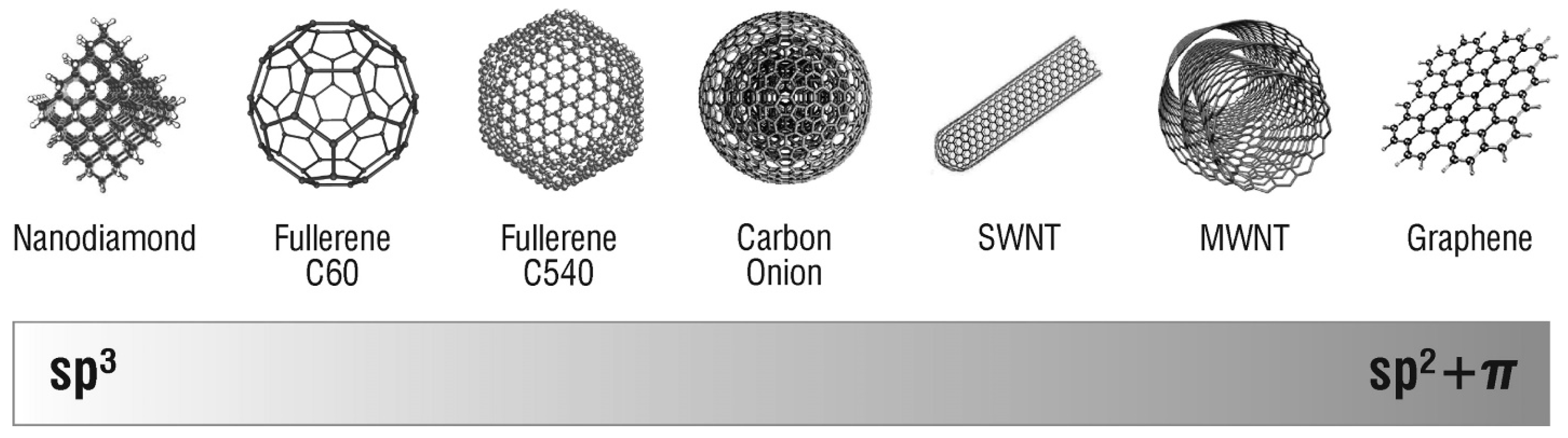
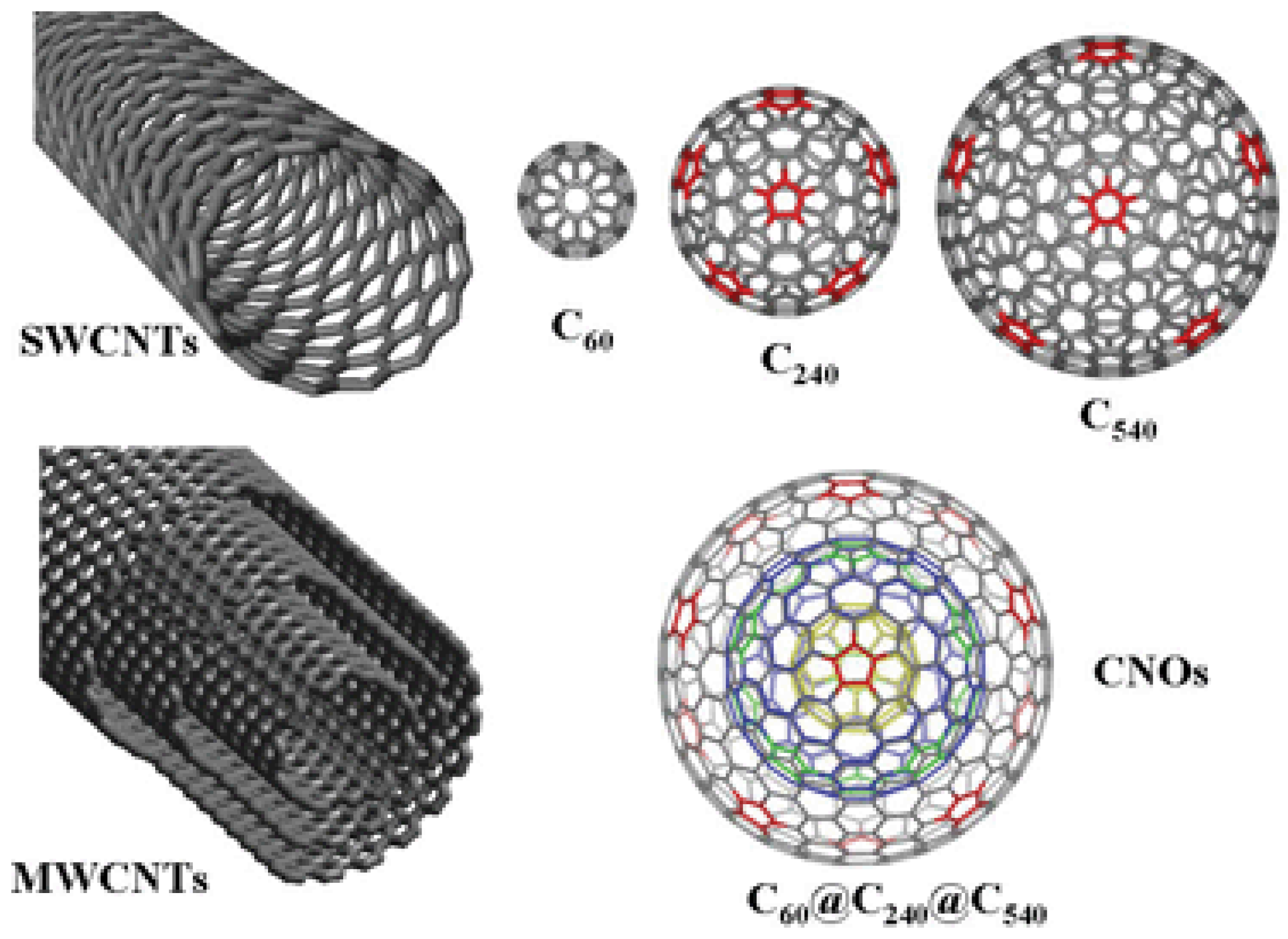
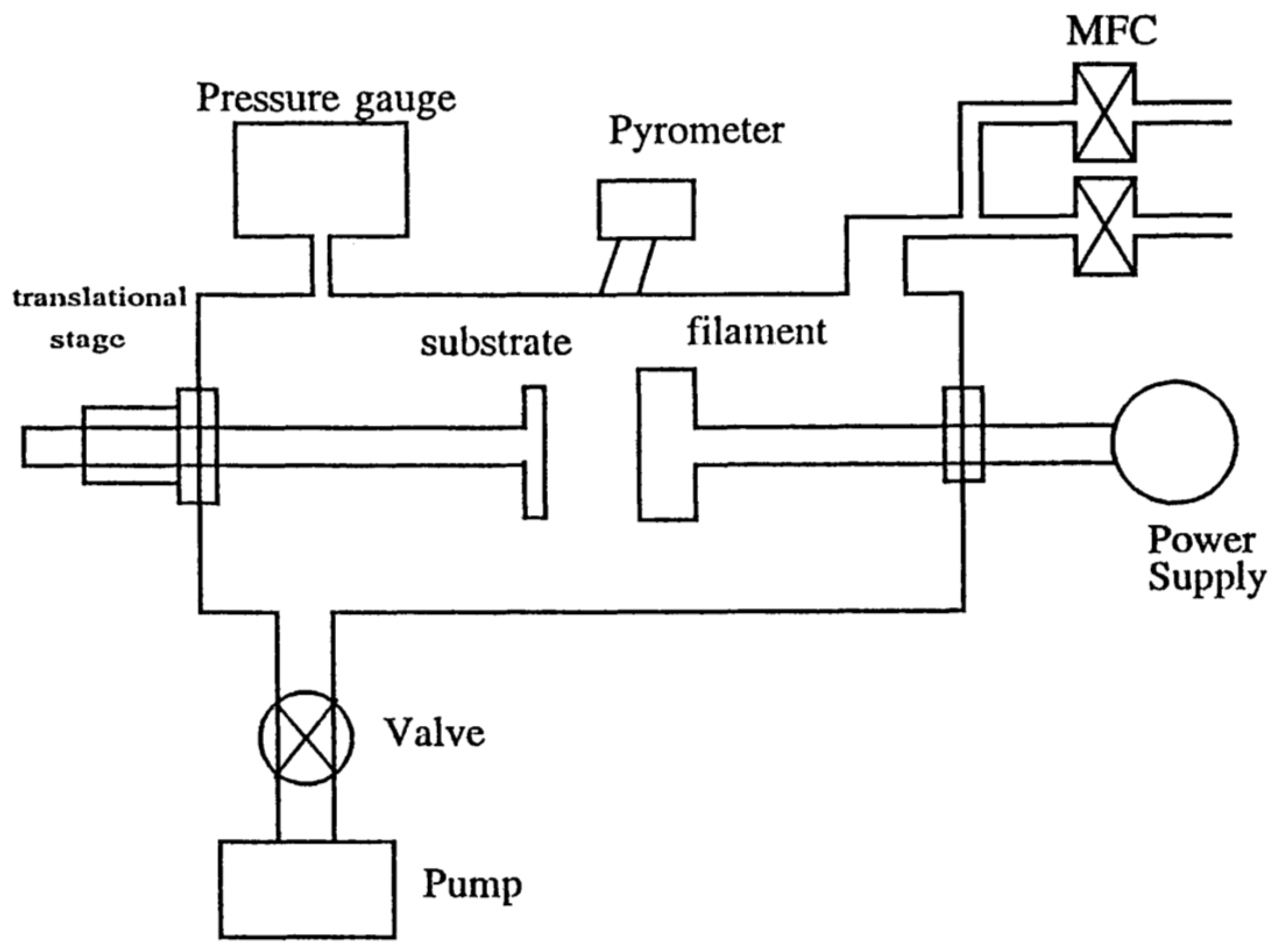
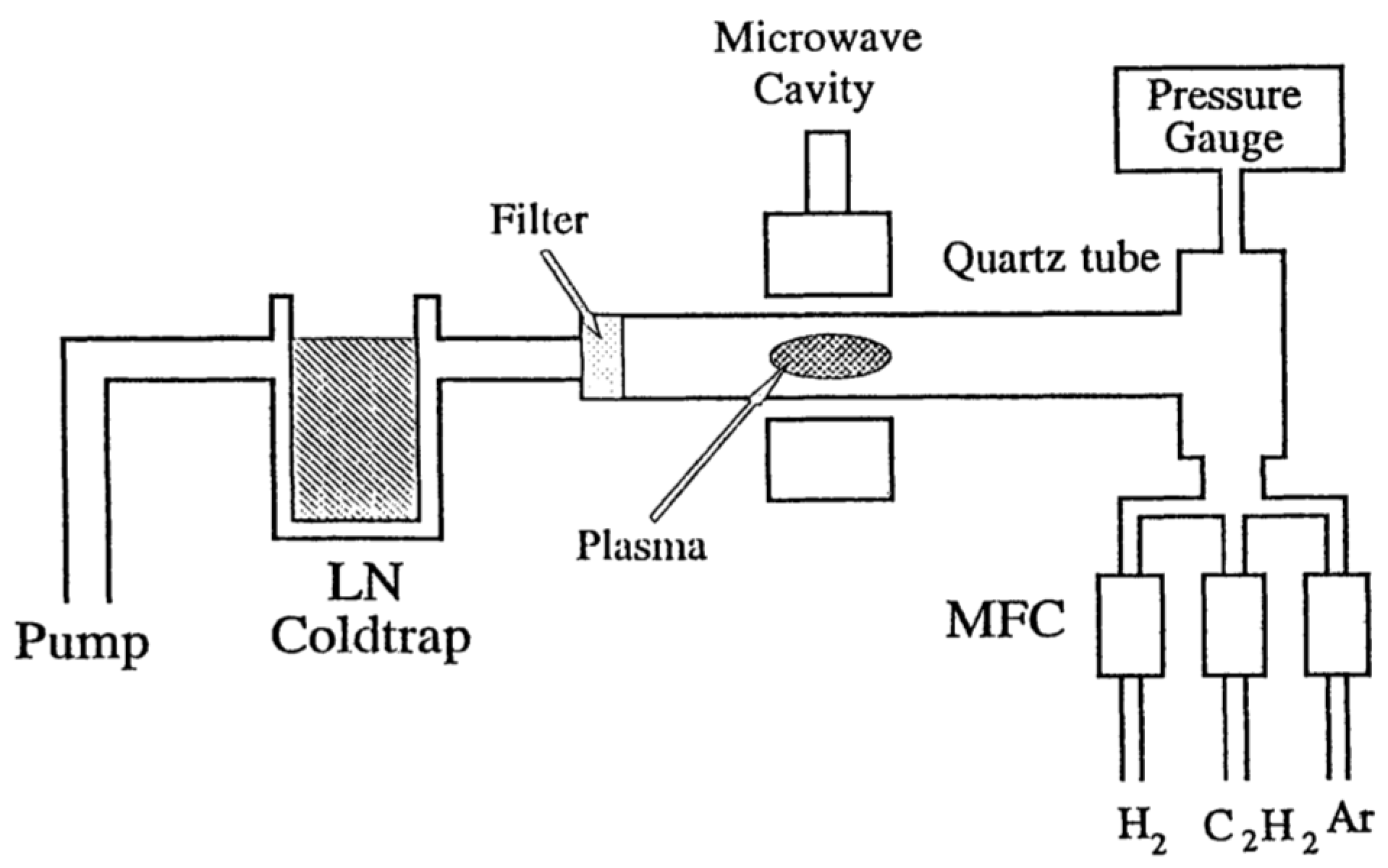
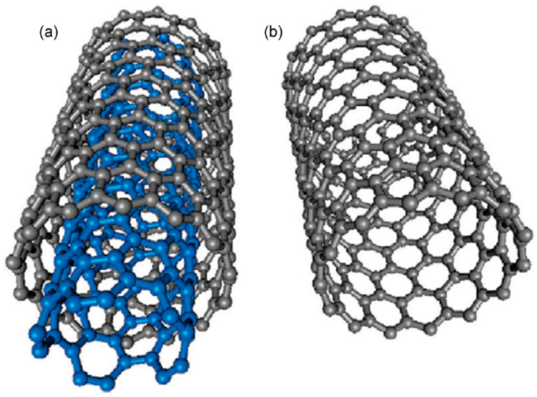
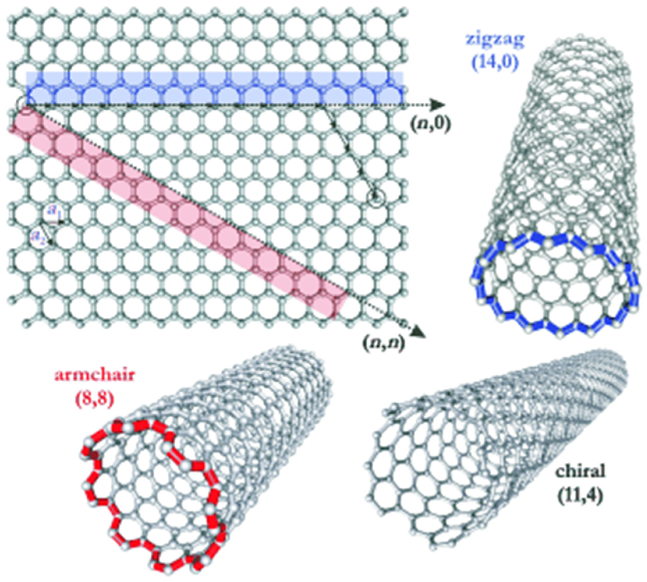
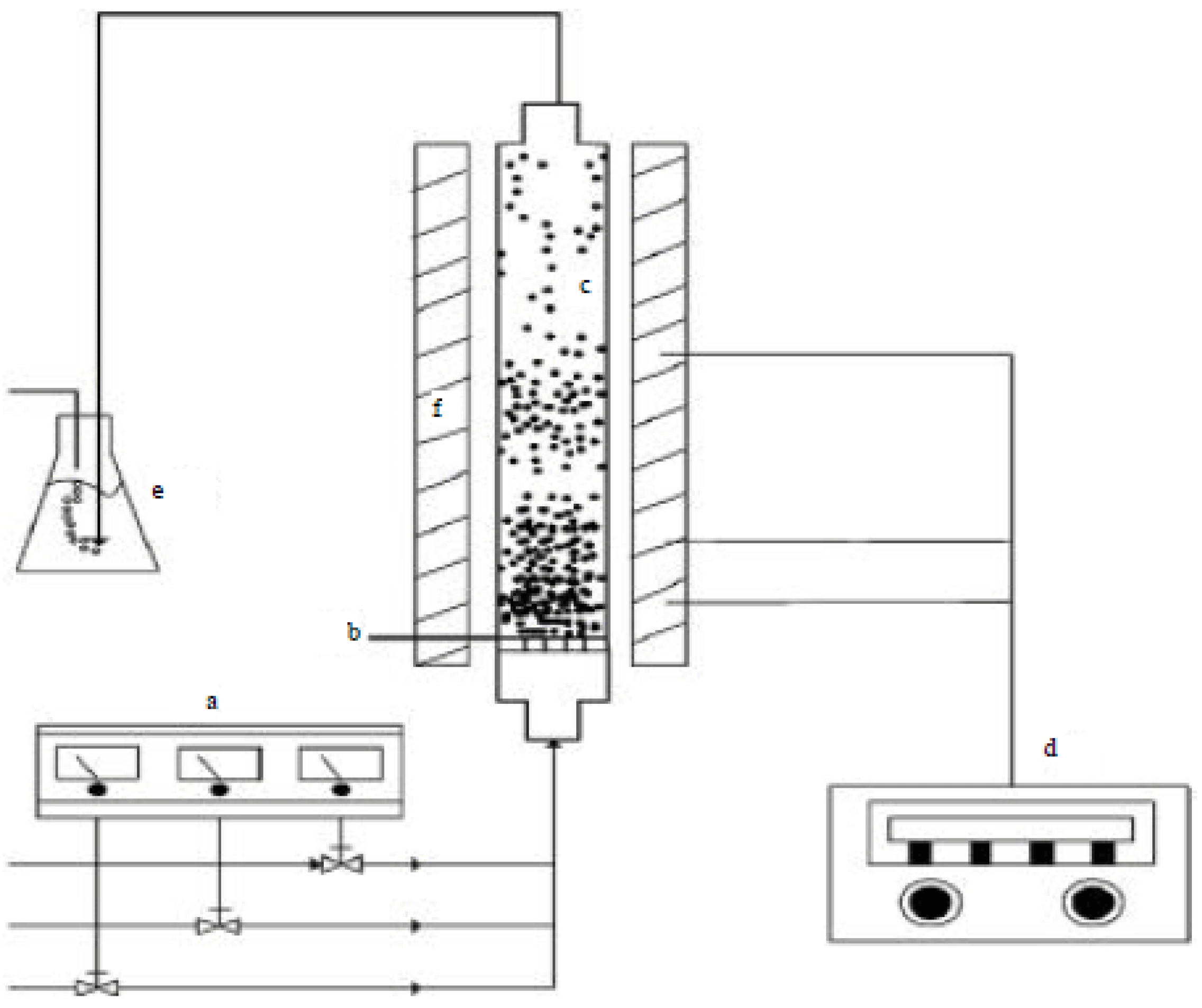
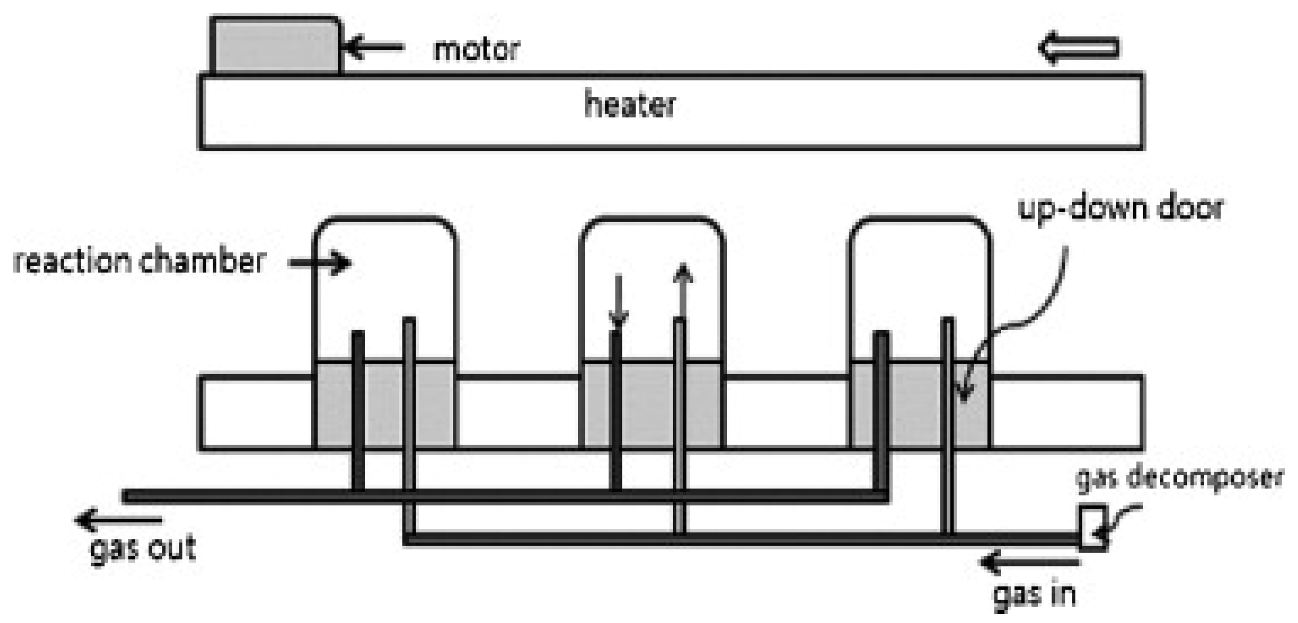
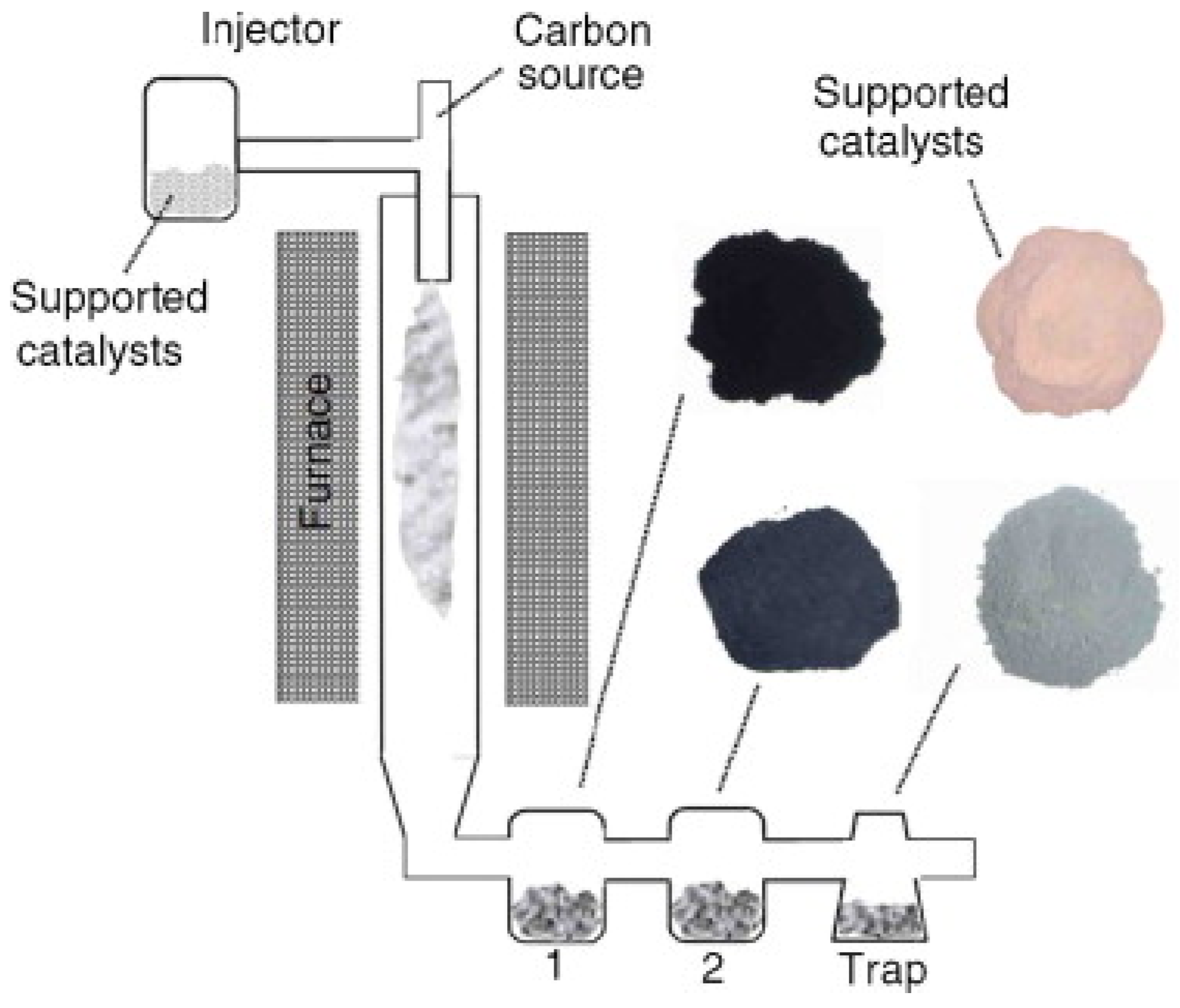
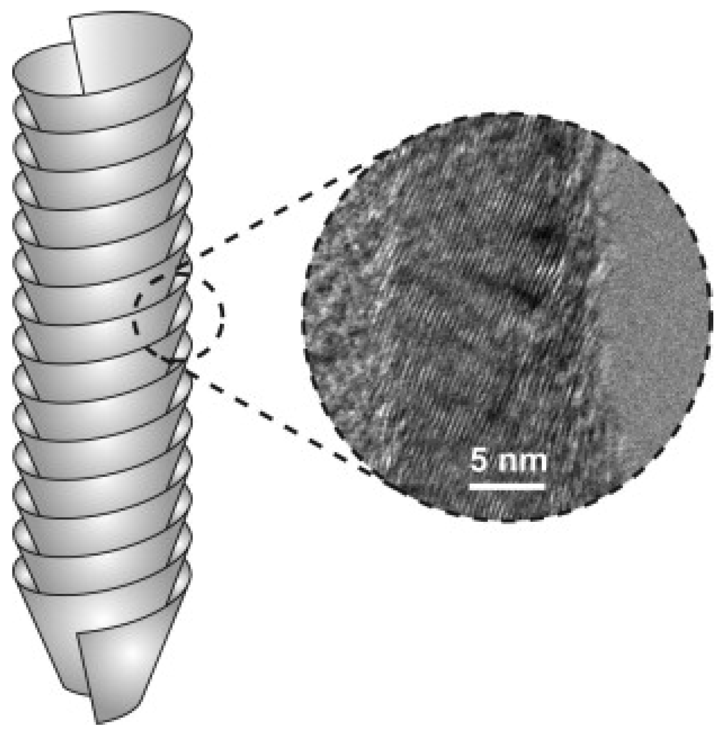
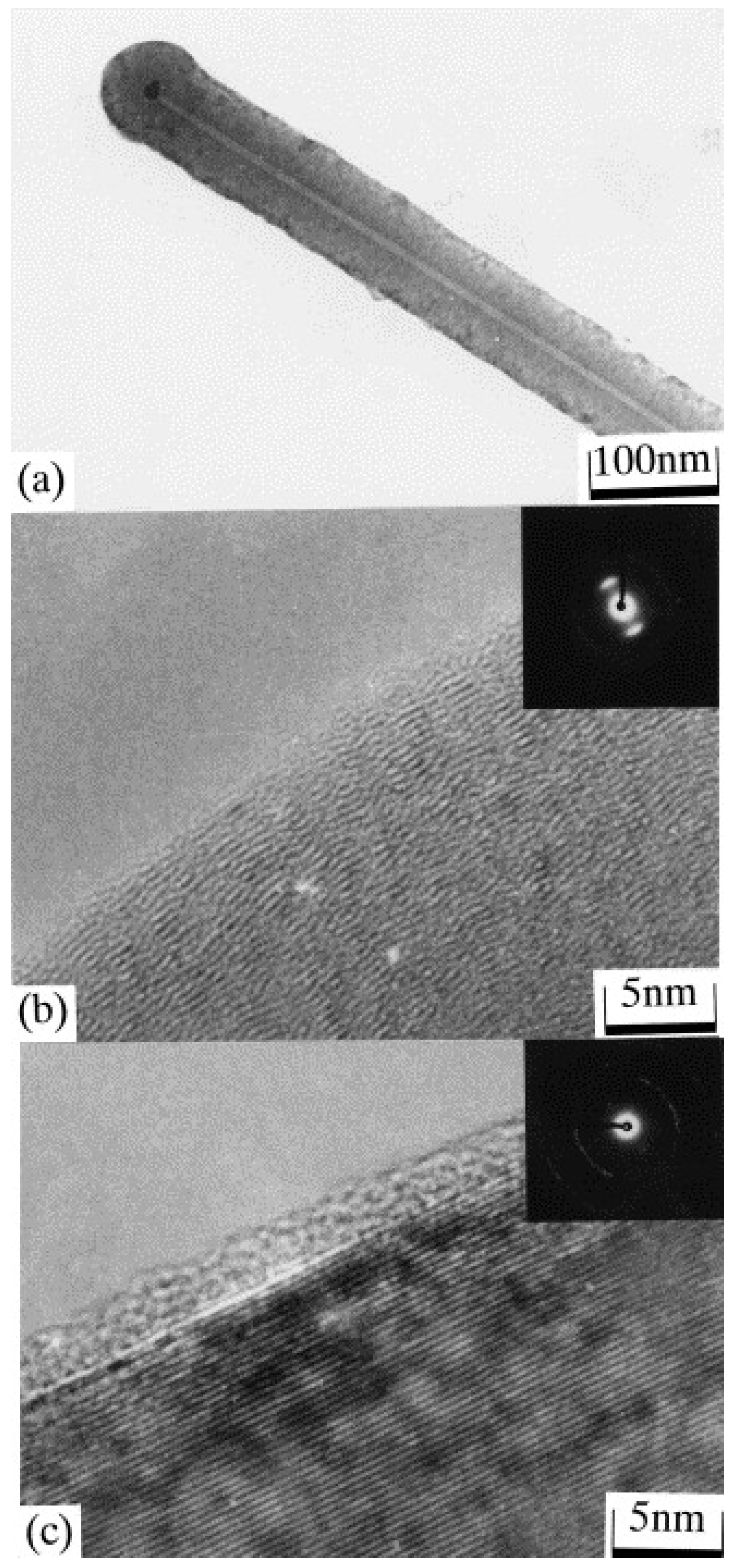
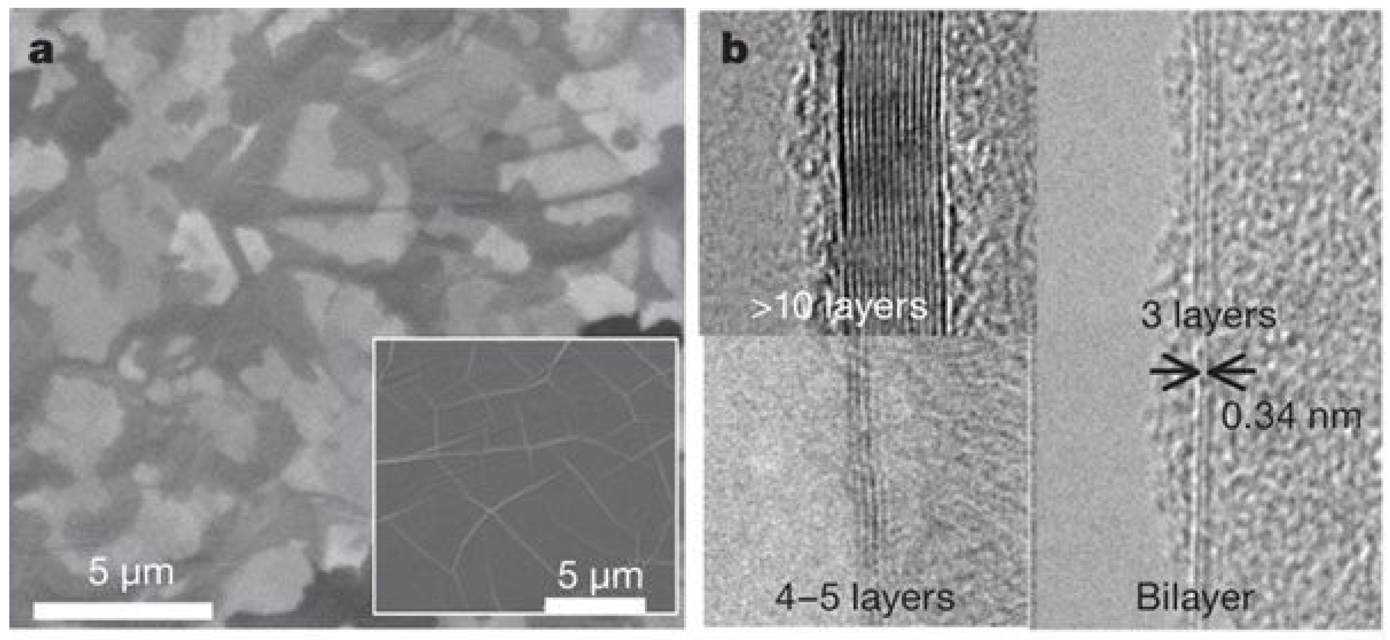
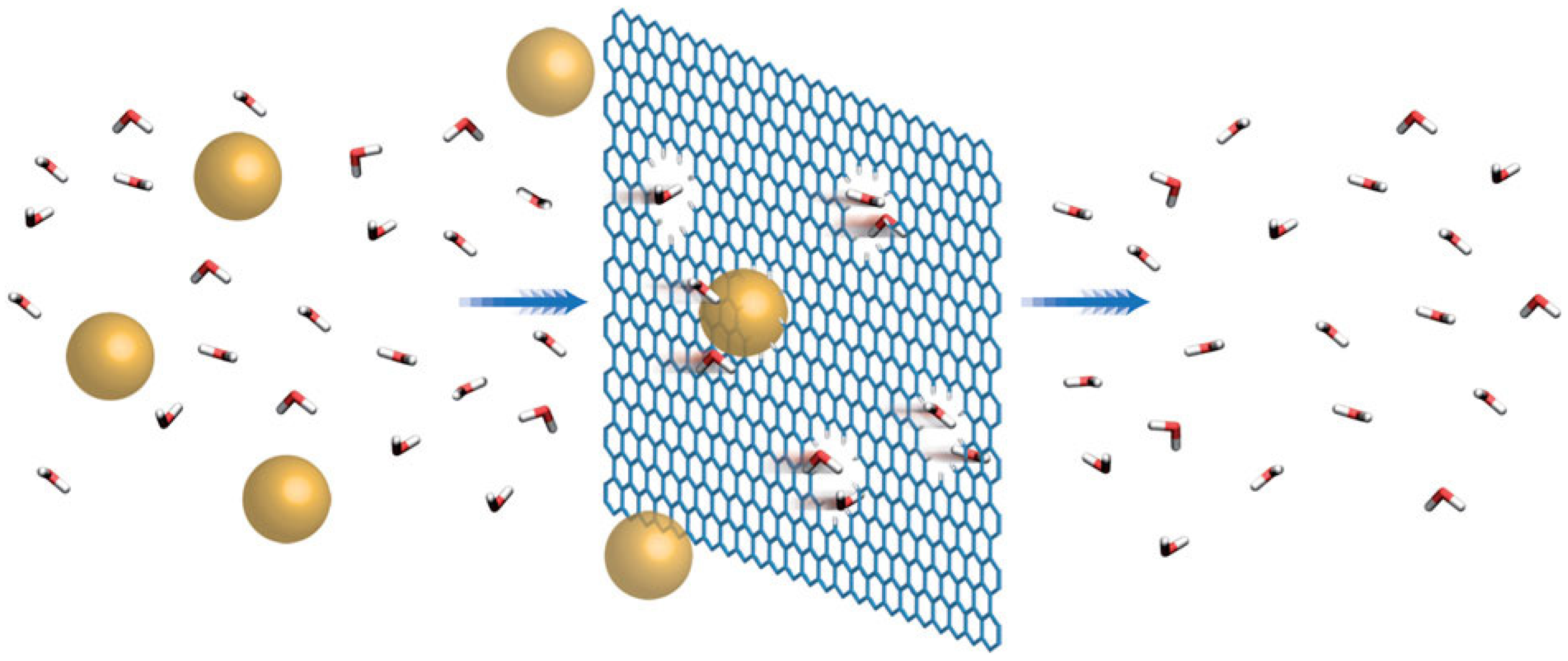
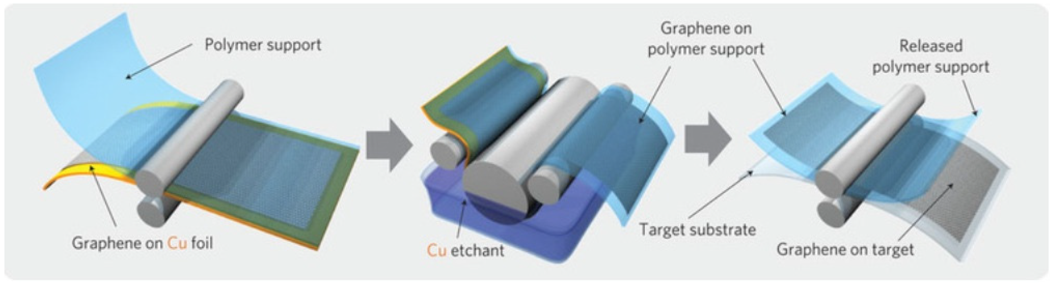
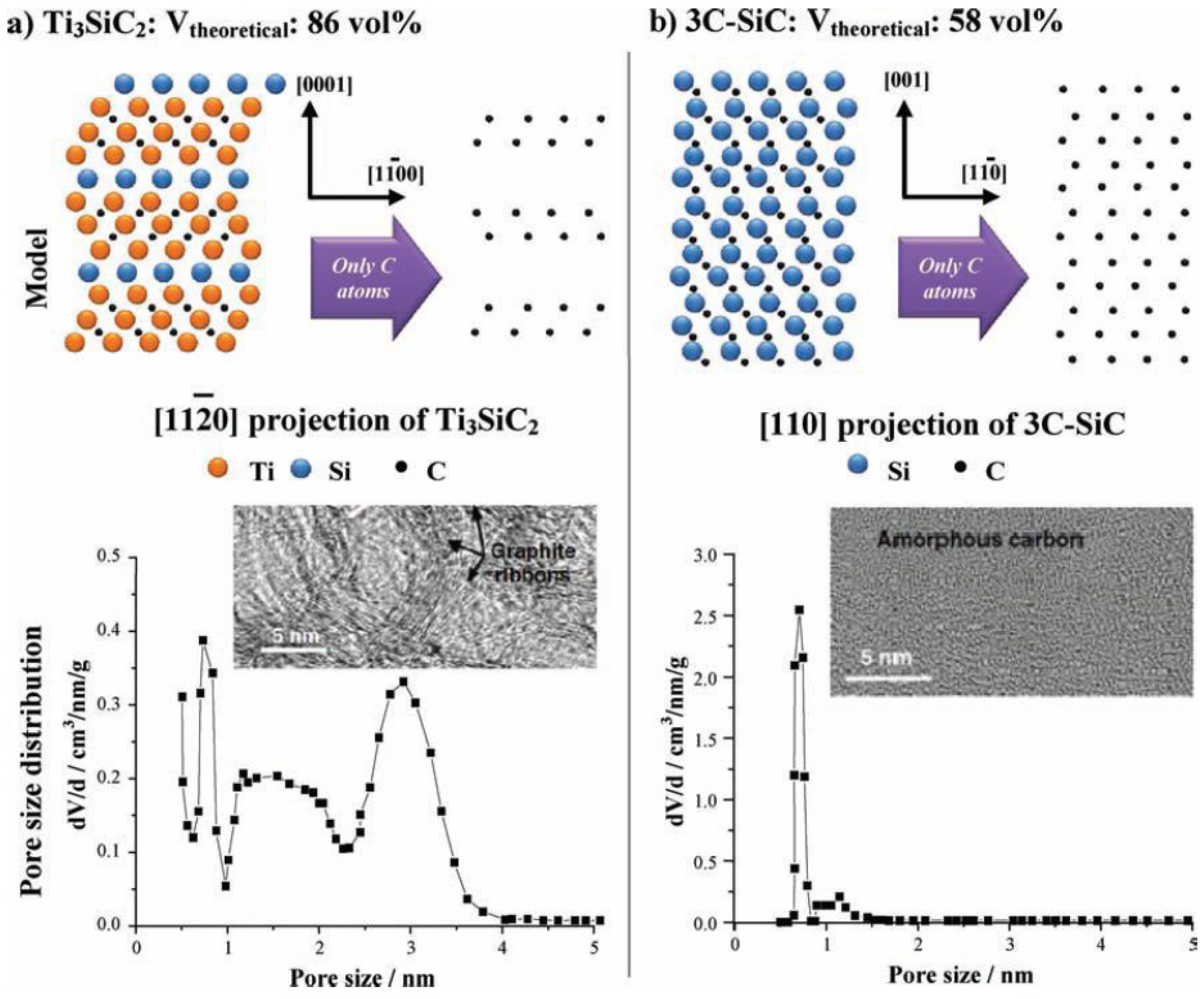
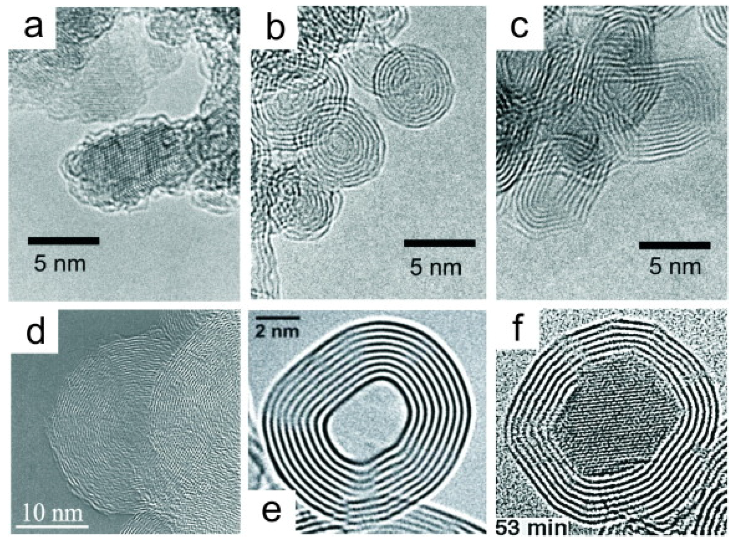
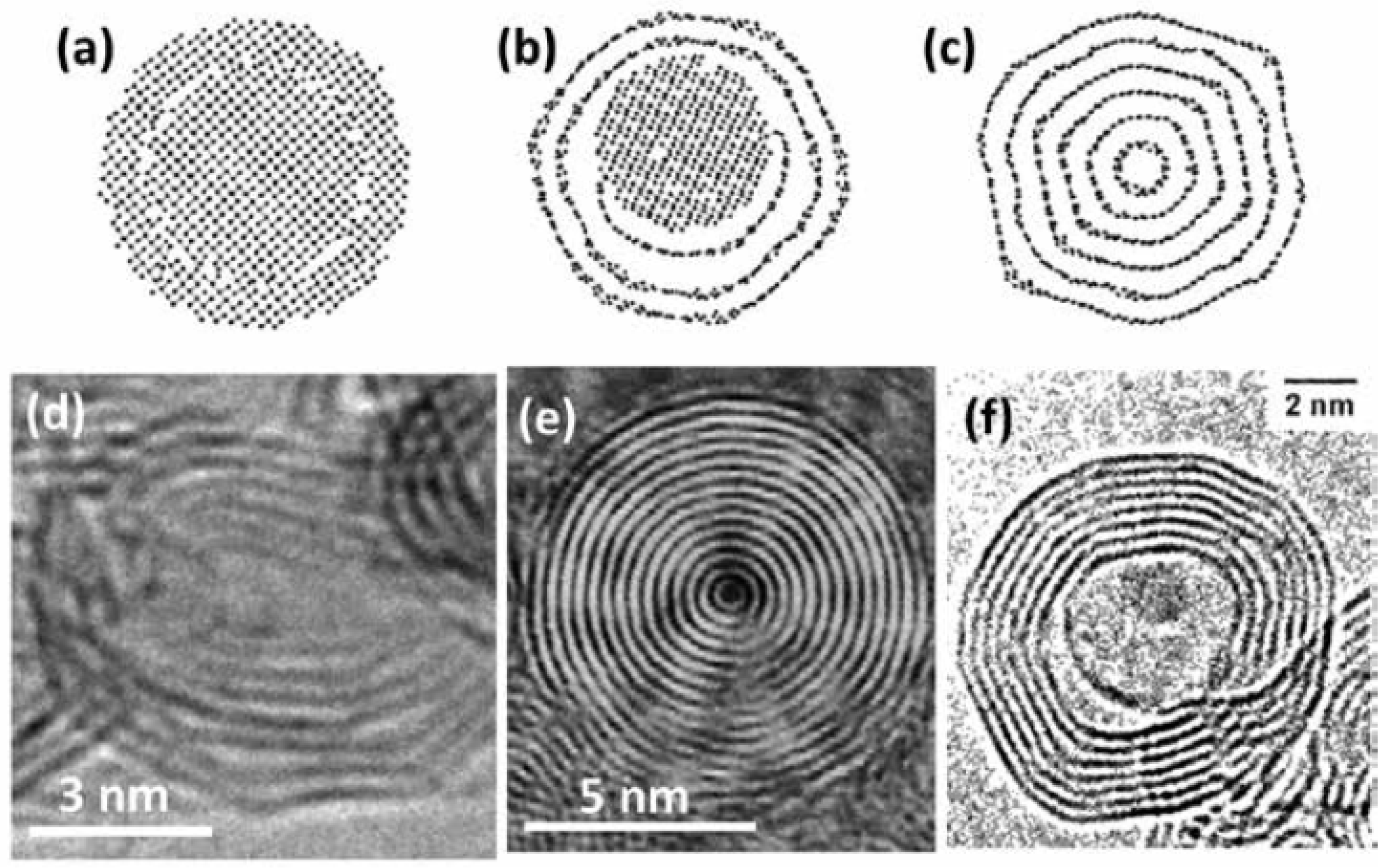
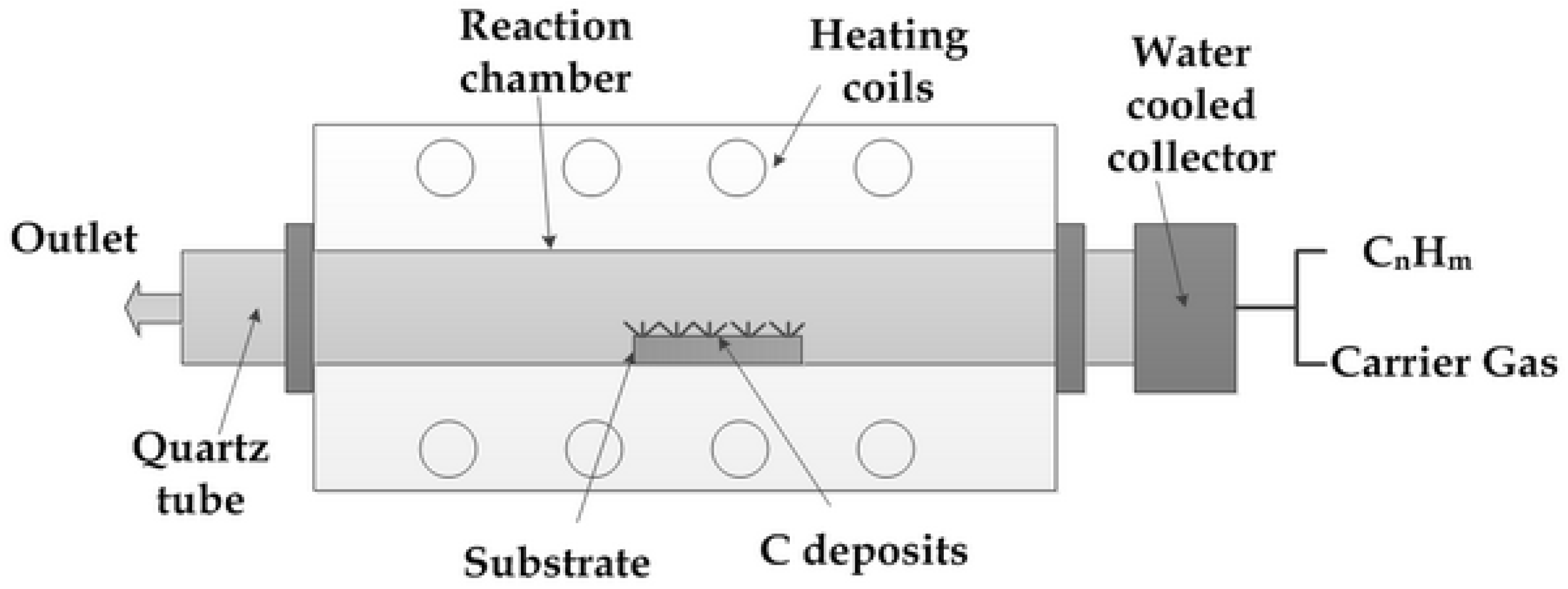
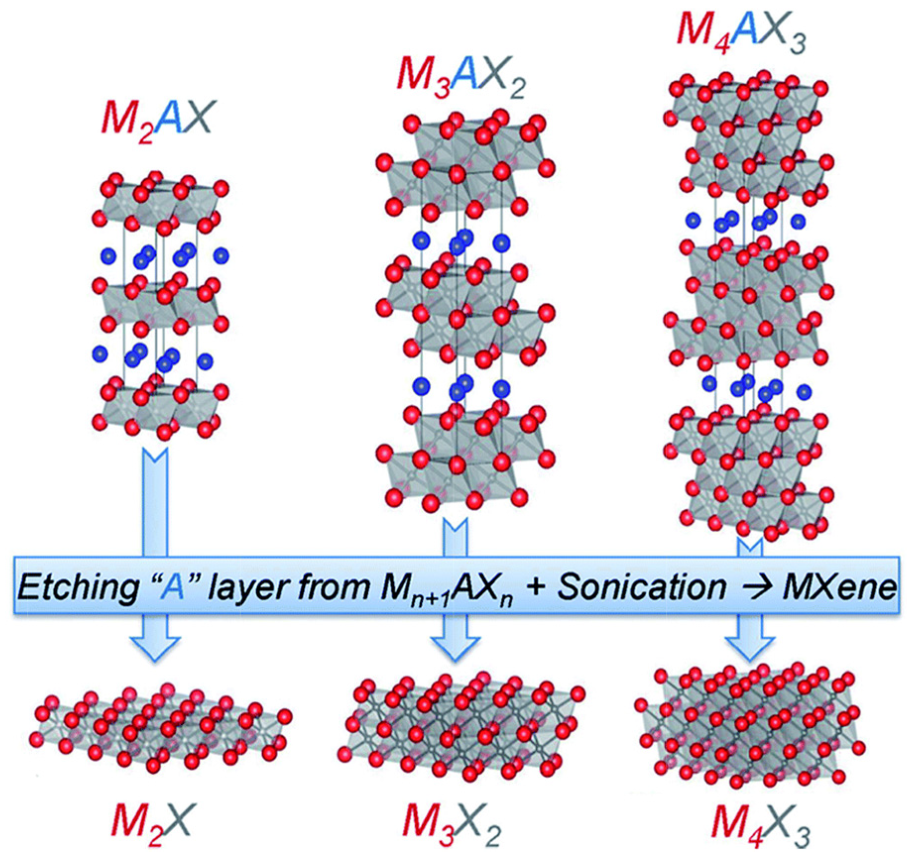
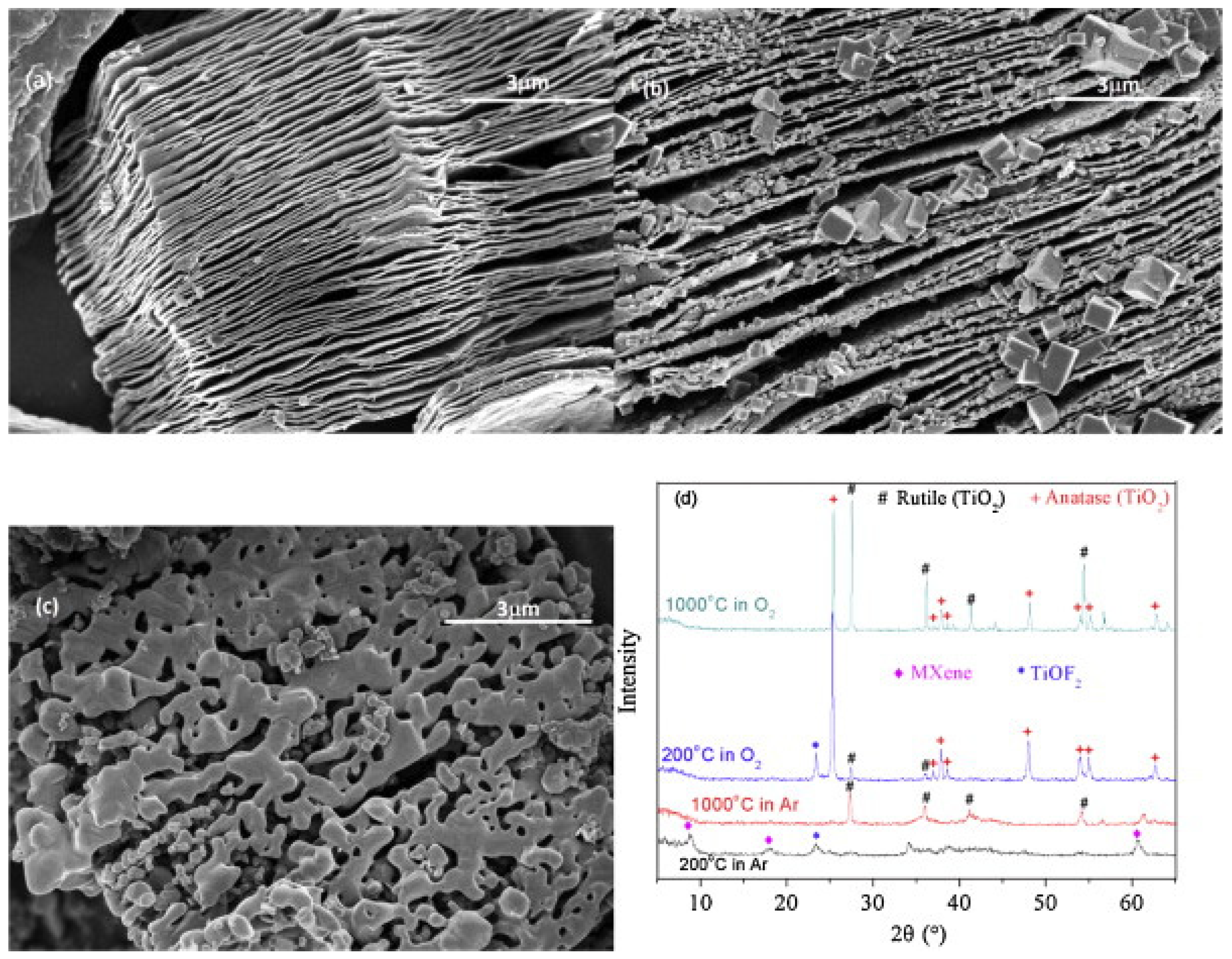
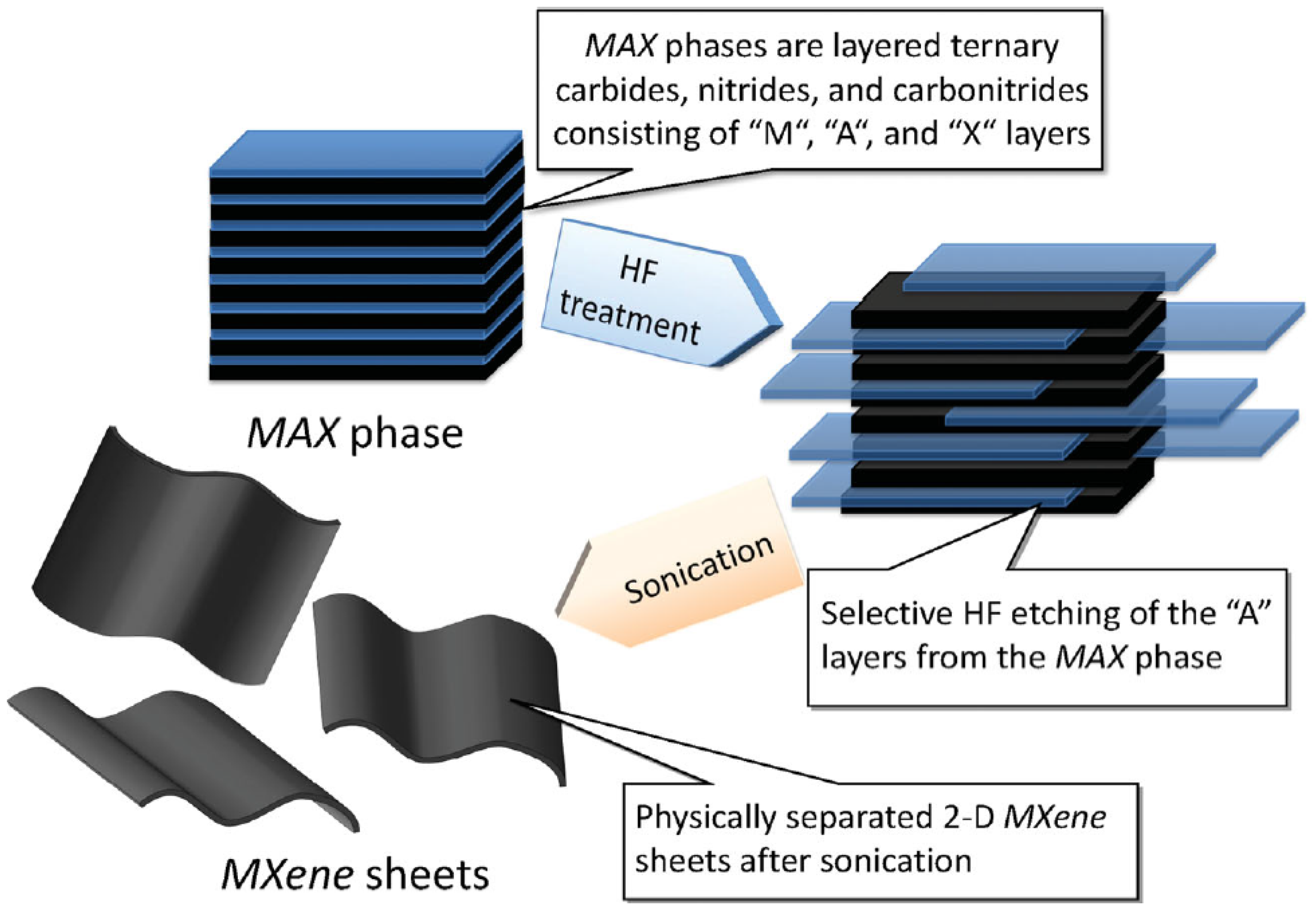
Table 1.
Catalytic production of CNTs by CVD.
| Catalyst | Carbon Source/Gas Phase | Temperature (°C) | Product | Reference |
|---|---|---|---|---|
| Co, Ni, Fe/MgO | CH4/H2 | 1000 | SWCNTs | [53] |
| Fe/Al2O3 | C2H4/N2, H2 | 650 | MWCNTs | [83] |
| Fe/Al2O3 | C2H4/N2, H2 | 500–700 | MWCNTs | [84] |
| Ni-Cu/Al2O3 | C2H4/N2, H2 | 850 | MWCNTs | [85] |
| Fe/SiO2/Al2O3 | Propylene/N2 | - | MWCNTs | [86] |
| Ni/SiO2 | CH4/Ar | 760 | SWCNTs | [87] |
| Fe/Al2O3 | Ethylene/N2, H2 | 550 | CNTs | [88] |
| Fe/silica | Acetylene/N2, H2 | 700 | CNTs | [89] |
| Fe/Al2O3, SiO2, TiO2 or ZrO2 | CH4/H2 | 650–800 | MWCNTs | [90] |
| LaCoO3 | C2H2/N2, H2 | 675–700 | MWCNTs | [91] |
| Co-Mo/SiO2 | CO | 750 | SWCNTs | [92] |
| LaCoO3 | C2H2, CH4/N2 | 700 | MWCNTs | [93] |
| Fe2O3 | CH4/Ar | 1000 | SWCNTs | [94] |
| Ni-Cu-Al | CH4/N2, H2 | 700–750 | CNTs | [95] |
| Fe | C6H6/Ar | 750 | MWCNTs | [96] |
| Ni/Fe/CO/HZSM-5 Zeaolite | Polypropylene (PP), polyethylene terephthalate (PET), polyethylene (PE), Polyvinyl chloride(PVC), PET/Ar, H2 | 400–900 | MWCNTs | [97] |
| NiO/HZSM-5 Zeolite | polypropylene (PP)/H2 | 500–800 | MWCNTs | [98] |
| Fe | PP,PE, PVC/Ar, H2 | 800 | MWCNTs | [99] |
| Si/SiO2 | CH4/H2 | 900 | SWCNTs | [100] |
| Fe2CO/Al2O3 | C2H4/Ar, H2 | 750 | MWCNTs | [101] |
| Si/SiO2/Al2O3 | C6H12/H2 | 750 | MWCNTs | [102] |
| Ni | C2H2/H2 | 550 | MWCNTs | [103] |
| Si | C2H2/H2, (Fe(CO)5 | 600–750 | MWCNTs | [104] |
| Si3N4 | C2H2 | 800–1000 | SWCNTs | [105] |
| Ba/Ca | C2H2/H2, Ar | 700 | MWCNTs | [106] |
| Fe(CO)5 | CO | 800–1200 | SWCNTs | [107] |
| Fe-Mo | CH4/Ar | 875 | DWCNTs | [108] |
© 2018 by the authors. Licensee MDPI, Basel, Switzerland. This article is an open access article distributed under the terms and conditions of the Creative Commons Attribution (CC BY) license (http://creativecommons.org/licenses/by/4.0/).
Share and Cite
MDPI and ACS Style
Manawi, Y.M.; Ihsanullah; Samara, A.; Al-Ansari, T.; Atieh, M.A. A Review of Carbon Nanomaterials’ Synthesis via the Chemical Vapor Deposition (CVD) Method. Materials 2018, 11, 822. https://doi.org/10.3390/ma11050822
AMA Style
Manawi YM, Ihsanullah, Samara A, Al-Ansari T, Atieh MA. A Review of Carbon Nanomaterials’ Synthesis via the Chemical Vapor Deposition (CVD) Method. Materials. 2018; 11(5):822. https://doi.org/10.3390/ma11050822
Chicago/Turabian StyleManawi, Yehia M., Ihsanullah, Ayman Samara, Tareq Al-Ansari, and Muataz A. Atieh. 2018. "A Review of Carbon Nanomaterials’ Synthesis via the Chemical Vapor Deposition (CVD) Method" Materials 11, no. 5: 822. https://doi.org/10.3390/ma11050822
Note that from the first issue of 2016, this journal uses article numbers instead of page numbers. See further details here.