Non-Dimensional Groups, Film Thickness Equations and Correction Factors for Elastohydrodynamic Lubrication: A Review


1
Engineering Design, Friedrich-Alexander-University Erlangen-Nuremberg (FAU), 91058 Erlangen, Germany
2
Department of Chemical Engineering, Biotechnology and Materials, University of Chile, Santiago 7820436, Chile
*
Authors to whom correspondence should be addressed.
Lubricants 2020, 8(10), 95; https://doi.org/10.3390/lubricants8100095
Submission received: 5 October 2020
/
Revised: 15 October 2020
/
Accepted: 16 October 2020
/
Published: 20 October 2020
(This article belongs to the Special Issue In Commemoration of Professor Duncan Dowson: Tribology: Hydrodynamics, Elastohydrodynamics and Biotribology)
Abstract
:Apart from complex numerical models to predict the tribological behavior of elastohydrodynamically lubricated contacts, non-dimensional similarity groups and analytically solvable proximity equations can be used to estimate integral fluid film parameters. Based upon the pioneering work presented by Dowson and Higginson as well as Blok and Moes, these approaches have been continuously improved over the years by modifications or correction factors to capture different contact geometries (line-, point- or elliptical contacts) as well as to include fluid compression, thermal, non-Newtonian, starvation or roughness effects. Consequently, this review article aims at systematically reviewing these modifications/corrections and discussing their applicability as well as limitations before presenting some recommendations for future research activities.
1. Introduction
Power transmission in machine elements or engine components such as rolling bearings, gears or cam/followers is generally achieved by concentrated rolling and rolling-sliding contacts, in which the rubbing bodies are locally elastically deformed due to the acting contact forces [1]. For dry contacts, the involved deformations, pressures and stresses can be approximated by the Hertzian theory [2]. In the presence of sufficient lubricant, a hydrodynamic pressure is built up and the contacting surfaces are at least partially separated by a thin fluid film [3,4]. If the local elastic deformation and the lubricant film thickness are on a similar order of magnitude, this condition is usually referred to as elastohydrodynamic lubrication (EHL) or, thermo-elastohydrodynamic lubrication (TEHL), when considering thermal effects as well.
For numerical modeling, Computational Fluid Dynamics (CFD)- or Navier-Stokes-based approaches are generally associated with high computational effort and numerical instabilities [5]. Therefore, the simulation of EHL contacts is usually done by applying the Reynolds equation [6] for hydrodynamics and solving the system of equations coupled with elastic deformation. For this purpose, multigrid and multilevel integration methods based upon finite difference approaches and iterative (weak) coupling with an elastic half-space theory [7,8] or fully (strong) coupled finite element approaches [9,10] have been utilized. A schematic representation of an infinite EHL line-contact with common input variables is illustrated in Figure 1.
In addition to these rather complex and time-consuming simulation programs that allow for the investigation of local and time-resolved phenomena, there are also some analytically solvable proximity equations for the simplified, integral calculation of important EHL film parameters such as the minimum film height hmin or central lubricant gap hc. These equations enable a fast and, in many cases, sufficiently accurate approximation as well as the incorporation into superordinate multi-body or system simulations for friction calculation or the identification of critical operating conditions of aggregates, machines or facilities. Most of these approaches, however, were established several decades ago and incrementally enhanced through modifications or correction factors by numerous authors based upon novel experimental/theoretical insights as well as advances in simulation and measurement technology. Therefore, this contribution aims to systematically present the evolution and most recent progress in film thickness estimation approaches, thus helping the interested reader to select the most suitable approach in terms of applicability and validity. For that purpose, this article follows a logical and chronological order. At first, non-dimensional groups are introduced in Section 2, which represent similarity indices for EHL contacts. Based upon that, the available proximity equations for the calculation of the minimum and central film thickness in infinite 2D line-, 3D point- or elliptical contacts are summarized in Section 3. Since these approaches may be subject to deviations under certain circumstances, correction factors for fluid compressibility (Section 4.1), thermal effects (4.2), non-Newtonian fluid behavior (4.3), starvation (4.4) as well as rough surfaces and asperity contact (4.5) are subsequently introduced. Finally, the applicability and limitations of the film thickness equations are discussed before presenting some recommendations for future research activities.
2. Non-Dimensional Groups
Based upon early numerical solutions [11], certain similarities were recognized and dimensionless groups were introduced to generalize calculations and results [12]. For an infinite 2D line-contact as well as a 3D point-contact, using the reduced Young’s modulus E’, the pressure-viscosity coefficient αp, the base viscosity η0, the effective velocity um, the effective radius R, the contact length l and the normal load F, Dowson and Higginson [13,14] defined the material parameter
the velocity parameter
the load parameter
as well as the fluid film parameters
and developed correlations between them (see Section 3). Typical ranges of these EHL parameters are summarized in Table 1.
Blok and Moes [16,17] showed that the four parameters of Dowson and Higginson can be unidirectionally transformed (i.e., re-transformation is not possible [1]) into three parameters thus introducing the modified load parameter
and the viscosity parameter
in addition to the lubricant film parameter
Another set of dimensionless groups were used by Greenwood [18], which can also be shortened and expressed in the Dowson & Higginson notation:
Later, Johnson [19] proposed parameters for the elasticity
the pressure-viscosity-relationship
and the film thickness
which can be transformed to the Blok/Moes notation. For completeness, it should also be noted that Habchi et al. [20] suggested the use of the Weissenberg number Γ [21], which characterizes the shear stress of inlet flow in relation to the Newtonian limit by means of the relaxation time λΓ, the shear rate , the shear stress τ and the shear modulus G [22]:
the Nahme-Griffith number [23], which describes the ratio of viscous heating to temperature-dependent viscosity changes using the temperature T and the thermal conductivity λ:
the limiting-shear-stress number with the limiting τl and unbound shear stress τu as well as the limiting stress-pressure coefficient λτ:
and the thermoviscous regime indicator
to distinguish between different friction regimes. These regimes were the linear (Wi < 1), non-linear viscous (Wi > 1, Li < 1, Ti < 100), plateau (Li > 2, Ti < 100) and thermoviscous (Ti > 100) traction regime. It is important to mention that the dimensionless parameters from Dowson/Higginson and Blok/Moes are the most frequently used in literature [15,24].
3. Film Thickness Equations
3.1. Line-Contacts (2D)
Dowson and Higginson [13,14] proposed an analytically solvable regression equation for the approximation of the minimum lubricant gap in an infinite 2D line-contact as a function of the dimensionless material, velocity and load parameters:
It can be seen that the load has only a rather small influence, while the material and velocity parameters, especially the product of velocity and viscosity, strongly affect the film thickness. This equation has been modified by Moes [16]:
whereas the parameters M and L can be utilized due to the transformability:
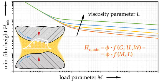
Consequently, the relation between film height, load and viscosity is illustrated in Figure 2. The equations for the minimum lubricant gap Hmin were further modified and extended based upon new insights and/or novel data from EHL simulations. For the 2D line-contact, the approaches from Dowson [25]:
as well as Jacobson and Hamrock [26]:
are prominent examples. An approximation for the central film thickness was introduced by Dowson and Toyoda [27]:
It is important to emphasize that the aforementioned approaches represent only approximations with a limited validity (see blue-shaded area in Figure 2, which shows the domain of the Dowson-Higginson [14] equation). If the respective validity range does not hold true, e.g., below the Martin-Gümbel asymptote in Figure 2, lubricant film heights tend to be underestimated. Thus, Johnson [19] distinguished four regimes depending on the fluid (iso-/piezoviscous) and material (rigid/elastic) properties [1,15] (Figure 3). Therefore, proximity equations for the isoviscous/rigid (IR) or Martin-Gümbel regime with hydrodynamic lubrication (small M, L = 0):
the isoviscous/elastic (IE) or Herrebrugh regime with easily deformable contacting bodies (soft EHL; large M and L = 0):
the piezoviscous/rigid (VR) or Blok regime (small M, large L):
and the piezoviscous/elastic (VE) or Dowson and Higginson regime with hard EHL contacts (large M, large L):
were defined [1].
Furthermore, Myers et al. [28] introduced a transition regime (TR in Figure 3), for which the following film thickness equations were proposed:
Based upon updated EHL simulations performed by Lubrecht [29] and Venner [30], Moes [31] presented a new approximation formula for the entire range of concentrated, lubricated 2D line-contacts (Figure 2), which utilizes asymptotic values for the lubricant film height:
with
Similar to this concept, Moes [32] suggested the following function fit for the central film height:
with
and the asymptotic approximations for the IR, IE, VR and VE regimes:
3.2. Point- and Elliptical Contacts (3D)
Furthermore, a relation between the non-dimensional groups and the minimum film thickness for 3D point-contacts was suggested by Evans and Snidle [33]:
as well as by Hamrock and Dowson [34] for elliptical contacts:
with the ellipticity parameter
and a flow velocity along the smaller half-axis. Chittenden et al. [35] extended this approach by varying flow direction and introduced a term considering the dependence on the ratio of the radii transversal to and in flow direction of the lubricant:
with:
Similar to the concept for 2D line-contacts from Moes [32], respective function fits for a 3D point-contact are given as:
with
For the central film thickness, respective formulas were suggested by Hamrock and Dowson [34]:
Furthermore, Nijenbanning et al. [36] suggested relations (Figure 4) for the central film thickness of 3D elliptical contacts:
with
Most of these approaches were developed based upon numerical data and give an almost constant ratio of central and minimum film thickness. However, this ratio may vary between 1 and 3 depending on M and L. Therefore, Sperka et al. [38] derived from experimental data an equation to predict this relation dependent on the pressure-viscosity coefficient αp:
4. Correction Factors
The described non-dimensional groups and film thickness equations deliver reasonable agreement with many lubricants as experimentally verified via interferometric film thickness measurements [37,39]. However, deviations can be observed under certain conditions due to fluid compressibility, thermal effects, shear-thinning, insufficient lubricant supply or surface roughness. All these aspects are not fully considered in the original numerical solutions, based upon which the equations in Section 3 were derived. These effects can be taken into account using corrections factors ϕx, which are multiplied with the film height parameter to obtain the corrected gap height:
Since the different correction factors feature specific applicability and limitations, they will be addressed in more detail hereinafter.
4.1. Fluid Compressibility
In the original numerical solutions [14], the density-pressure-relationship according to Dowson and Higginson [40] was applied. Yet, the density was not considered as an input variable in the non-dimensional groups and film thickness equations. Although lubricant compressibility plays no major role in the minimum film formation, the central film thickness particularly can be influenced under certain conditions [41]. According to Venner and Bos [42] and later verified by Habchi and Bair [43], predictions for compressible fluids can be adjusted from the incompressible approximations with the base density ρ0 using the following correction factor
whereby any model could be utilized for calculating the density for the respective Hertzian pressure ρ(pH) [44].
4.2. Thermal Effects
The deduction of non-dimensional parameters and film thickness equations was based upon the isothermal solution of the EHL problem. However, for high speeds and velocity differences of the rubbing surfaces (slip), local temperatures in the fluid can significantly exceed the mass temperatures of the contacting bodies due to lubricant compression at the contact inlet and shearing in the contact center, thus reducing viscosity and, hence, film thickness [45]. To approximate these thermal aspects, a first theoretical approach to capture the effects coming from inlet compression and shearing was suggested by Greenwood and Kauzlarich [46]. The proposed correction factor was given as:
using the constant Ts and exponent n from the Slotte equation [47] to describe the viscosity-temperature behavior as well as thermal conductivity λ of the given lubricant. However, this correlation tends to overestimate the influence of temperature at high speeds due to the application of the Crook approximation [48,49] of the film shape, which only holds true for a rolling speed of a few m/s [46]. Further, Murch and Wilson [50] introduced a thermal stress parameter, which was subsequently simplified by Jackson [51]:
with the viscosity-temperature coefficient β to determine the thermal film thickness reduction:
Since the fluid film height is mostly influenced by the viscosity at the contact inlet, thermal effects due to shearing in the center are less relevant. Therefore, these approaches were designed for pure rolling conditions. To extend their applicability, Wilson and Sheu [52] introduced a dependence on the slide-to-roll ratio (see Figure 5):
which corresponds to the Murch and Wilson formulation for pure rolling conditions. These approaches were further modified by e.g., Pandey and Gosh [53]:
adapted for specific lubricants [54] or modified for a combination with non-Newtonian fluid behavior [55].
4.3. Non-Newtonian Fluid Behavior
Similar to thermal effects, shear thinning of the lubricant at high speeds and velocity differences can also affect the minimum film height and change the film profile in the contact center [56]. Therefore, Bair [22] suggested a correction factor
for a lubricant with Carreau viscosity behavior [57] depending on the Carreau exponent n and the Weissenberg number. This approach was extended and distinguished for minimum and central lubrication film height by Khonsari et al. for line-contacts [58]
and for point-contacts [59]
respectively, or by Habchi et al. [60]:
The latter were derived for fluids with Carreau viscosity and two Newtonian plateaus.
4.4. Starvation
Assuming an unlimited oil supply, the EHL pressure build-up can start at any distance from the contact center. However, a lubricant contact may suffer from starvation due to high speeds, highly viscous lubricants, or insufficient lubricant supply. The lubricant supply is such that the starting point of the pressure generation is closer to the contact and the generated film thickness is significantly smaller compared to the fully flooded case [61]. The latter is reached when the distance between contact and inlet, the so-called inlet meniscus, ceases to affect the minimum film thickness to any significant extent. Therefore, Hamrock and Dowson [62] suggested taking the fully flooded-starved boundary:
and the inlet location m into account to calculate correction factors for the minimum lubricant gap
and the central film thickness:
4.5. Surface Roughness and Asperity Contact
It is well accepted that the surface topography in terms of stochastic, manufacturing-related deviations from the smooth, ideal flat surface or intentionally produced surface features such as surface textures has a decisive impact on the film formation in EHL contacts [65,66,67,68,69]. While waviness or roughness oriented transversely to the direction of motion can have a positive effect on the global lubricant film height under certain circumstances [70,71], structures oriented in the direction of motion typically induce negative effects [72,73]. In addition, the consideration of rough surfaces is often accompanied by locally strongly increased pressures [74,75,76]. With decreasing lubricant film heights, simultaneous solid asperity contact and hydrodynamic pressure build-up can occur, thus sharing the normal load, which is referred to as mixed lubrication [77]. A first approach to considering the influence of surface topography was introduced by Zhu and Cheng [78] based upon the statistical consideration of surface asperities in terms micro-hydrodynamics [79] and load sharing [80,81]. Similar to the flow factor method from Patir and Cheng [82], they derived corresponding correction factors to adjust the minimum and central film height depending on the orientation of the surface topography and the ratio of the smooth lubricant gap to the quadratic mean surface roughness (Figure 6). To quantify the spatial orientation, the so-called Peklenik factor γ can be used as a quotient of the characteristic correlation lengths of two mutually orthogonal measurement directions [83]. Using deterministic calculations assuming full film lubrication, Kumar et al. [84] derived a correction factor for 2D line-contacts depending on the normalized amplitude A of the surface waviness or roughness:
However, it is important to mention that the wavelength was assumed to be constant for the analysis and only pure rolling conditions were considered, thus neglecting the impact of velocities and slip. Using an stochastic approach similar to Zhu and Cheng, Masjedi and Khonsari [85] developed correction factors for adjusting the minimum film thickness:
and central film thickness
5. Applicability, Limitations and Future Directions
An overview of the applicability for different contact forms and conditions of the presented film thickness approximations is displayed in Table 2 and Figure 7.
As can be seen in Table 2 and Figure 7, there are many approaches for film thickness equations, ranging from the infinite line-contact to point- or elliptical contacts. Yet, these equations were originally derived from different numerical data and, therefore, have individual ranges of validity. While comparisons of the approaches for 2D line-contacts are practically not possible, this possibility exists for point contacts. The experimental studies from Chaomleffel et al. [37] using interferometric film thickness measurements demonstrated reasonable agreement for the central film thickness even when using lubricants with shear thinning characteristics and applying the equations outside their stated ranges. However, the minimum film thickness outside the proposed domain of the equations was greatly influenced and could not be predicted for all conditions. In this context, the usage of other rheological models, e.g., from Eyring [87] or Lee-Hamrock [88], seems reasonable (see Section 4.5). Wheeler et al. [86] came to similar conclusions regarding the accuracy of the equations when predicting the central film height and comparing these values with numerical predictions. They also reported on some shortcomings for heavily loaded contacts with slow entrainment and recommended the use of the Chittenden formulation [35] for the central film height and the Nijenbanning model [36] for the minimum lubricant gap.
When analyzing the film thickness equations in detail, it becomes evident that they only apply for stationary load cases. However, real operating conditions of machine elements or engine components are never completely stationary, and time dependencies are usually present or even dominant. For the extreme scenario of pure impact EHL, Wang et al. [89]
as well as Venner et al. [90]
suggested equations for the minimum central film thickness in a piezoviscous line- and point-contact, respectively, which show similarities to the classical EHL contact. Nevertheless, there is still more potential for future enhancement and extension of the film thickness equations towards transient effects. In this regard, the influence of surface properties and topographies can be also seen, which becomes even more important in the context of start-stop-operations, low viscosity lubricants, as well as the trend to operate under mixed lubrication [91]. This applies for manufacturing-related surface roughnesses and designed surface textures or even thin coatings [10,92]. Even though they can already be deterministically modelled by advanced numerical approaches across different scales [93], apart from [78,84,85], surface properties have not yet found their way into analytically solvable film thickness equations. This could be done based upon the development of further correction factors and/or by using the existing non-dimensional groups. In addition, modern machine learning (ML) or artificial intelligence (AI) algorithms, such as artificial neural networks (ANN), could play a decisive role in an efficient and accurate way, see Table 3. Properly trained models can have an excellent predictive power with a high level of correlation between calculations and simulation or experimental data [94]. Thereby, ML algorithms could be interpreted as a kind of black-box, which determines relevant EHL result variables depending on the input parameters (see Figure 1). In this regard, the prediction can go far beyond the minimum or central lubricant gap calculated in the analytical film thickness equations and also include the maximum pressure, shear rate or temperature rise. Furthermore, locally and time-resolved prediction models are conceivable.
To summarize, although the equations describing the film thickness were developed several decades ago, their use is still widespread and reasonable due to the fact that good predictions of film thickness are possible with negligible computing time. However, it is highly recommended to consider the validity range of the equations applied. Furthermore, the available correction factors should be evaluated to estimate a possible influence of thermal or non-Newtonian effects as well as the surface topography at least in a first approximation. In summary, there is still potential for extending the fluid film equations, especially regarding transient effects (time-varying stress collectives as well as surface properties and topography).
Author Contributions
Conceptualization, M.M.; methodology, M.M. and A.R.; investigation, M.M. and A.R.; Writing—Original draft preparation, M.M. and A.R.; Writing—Review and editing, M.M., M.B., S.W. and A.R. All authors have read and agreed to the published version of the manuscript.
Funding
This work was supported by ANID-CONICYT within the project Fondecyt 11180121 as well as the VID of the University of Chile in the framework of “U-Inicia UI013/2018”.
Acknowledgments
M.M., M.B. and S.W. gratefully acknowledge the continuous support of Friedrich-Alexander-University Erlangen-Nuremberg (FAU), Germany. S. Tremmel (Engineering Design and CAD, University of Bayreuth, Germany), S. Schwarz and S. Wirsching (Engineering Design, FAU Erlangen, Germany) are thanked for the fruitful discussions.
Conflicts of Interest
The authors declare no conflict of interest.
Nomenclature
| aH | small Hertzian half-axis |
| A | normalized amplitude |
| bH | large Hertzian half-axis |
| Ei | Young’s modulus |
| E’ | reduced Young’s modulus |
| F | normal load |
| gi | Greenwood parameter |
| G | material parameter |
| G | effective liquid shear modulus |
| h | lubricant gap |
| hc | central lubricant gap |
| hliq | lubricant layer height |
| hmin | minimum lubricant gap |
| hn | film thickness derived from Newtonian calculation |
| H | fluid film parameter |
| H00 | asymptote parameter |
| Hc | central fluid film parameter |
| Hmin | minimum fluid film parameter |
| k | ellipticity parameter |
| l | line-contact length |
| L | viscosity parameter |
| m | inlet meniscus |
| m* | fully flooded-starved boundary |
| M | load parameter |
| n | Slotte exponent |
| n | Carreau exponent |
| Na | Nahme-Griffith number |
| p | pressure |
| pH | Hertzian pressure |
| PE | elasticity parameter |
| Pα | pressure-viscosity parameter |
| Q | thermal stress parameter |
| r | asymptote exponent |
| Ri | Radius |
| s | asymptote exponent |
| SRR | slide-to-roll ratio |
| t | asymptote exponent |
| T0 | reference temperature |
| Ts | Slotte constant |
| ui | velocity |
| um | hydrodynamic effective velocity |
| U | velocity parameter |
| V | dimensionless hardness number |
| W | load parameter |
| αp | pressure-viscosity coefficient |
| β | viscosity-temperature coefficient |
| γ | Peklenik factor |
| shear rate | |
| η | viscosity |
| η0 | base viscosity |
| η∞ | second Newtonian viscosity |
| θm | fractional film content |
| κ | ellipticity parameter |
| λ | thermal conductivity |
| λτ | limiting stress-pressure coefficient |
| λΓ | relaxation time |
| Λ | fluid film parameter |
| νi | Poisson’s ratio |
| ρ | density |
| ρ0 | base density |
| σ | quadratic mean surface roughness |
| τ | shear stress |
| τl | limiting shear stress |
| τu | unbound shear stress |
| ϕi | correction factor |
| Γ | Weissenberg number |
References
- Van Leeuwen, H.H.; Schouten, M.J.W. Die Elastohydrodynamik: Geschichte und Neuentwicklungen; VDI Verlag: Düsseldorf, Germany, 1995. [Google Scholar]
- Hertz, H. Über die Berührung fester elastischer Körper. J. Für Die Reine und Angew. Math. 1882, 1882, 156–171. [Google Scholar]
- Czichos, H.; Habig, K.-H. Tribologie-Handbuchb. Tribometrie, Tribomaterialien, Tribotechnik; Springer Fachmedien Wiesbaden: Wiesbaden, Germany, 2015; ISBN 978-3-8348-2236-9. [Google Scholar]
- Gohar, R. Elastohydrodynamics; Horwood, E., Ed.; Halsted Press: Chichester, NY, USA, 1988; ISBN 9780853128205. [Google Scholar]
- Hartinger, M.; Dumont, M.-L.; Ioannides, S.; Gosman, D.; Spikes, H. CFD Modeling of a Thermal and Shear-Thinning Elastohydrodynamic Line Contact. J. Tribol. 2008, 130, 41503–4150316. [Google Scholar] [CrossRef]
- Reynolds, O. On the Theory of Lubrication and Its Application to Mr. Beauchamp Tower’s Experiments, Including an Experimental Determination of the Viscosity of Olive Oil. Philos. Trans. R. Soc. Lond. 1886, 177, 157–234. [Google Scholar]
- Venner, C.H.; Lubrecht, A.A. Multigrid techniques: A fast and efficient method for the numerical simulation of elastohydrodynamically lubricated point contact problems. Proc. Inst. Mech. Eng. Part J J. Eng. Tribol. 2000, 214, 43–62. [Google Scholar] [CrossRef]
- Venner, C.H.; Lubrecht, A.A. Multilevel Methods in Lubrication; Elsevier: Amsterdam, The Netherlands, 2000; ISBN 0-444-50503-2. [Google Scholar]
- Habchi, W.; Demirci, I.; Eyheramendy, D.; Morales-Espejel, G.; Vergne, P. A finite element approach of thin film lubrication in circular EHD contacts. Tribol. Int. 2007, 40, 1466–1473. [Google Scholar] [CrossRef]
- Habchi, W. Finite Element Modeling of Elastohydrodynamic Lubrication Problems; John Wiley & Sons Incorporated: Newark, NJ, USA, 2018; ISBN 978-1119225126. [Google Scholar]
- Dowson, D.; Higginson, G.R. A numerical solution to the elasto-hydrodynamic problem. J. Mech. Eng. Sci. 1959, 1, 6–15. [Google Scholar] [CrossRef]
- Dowson, D.; Song, E.S.; Taylor, C.M. Non-Dimensional Groups in Elastohydrodynamic Lubrication. In Thin Films in Tribology, Proceedings of the 19th Leeds-Lyon Symposium on Tribology, Leeds, UK, 8–11 September 1993; Elsevier: Amsterdam, The Netherlands, 1993; pp. 237–242. ISBN 9780444897893. [Google Scholar]
- Dowson, D.; Higginson, G.R. The Effect of Material Properties on the Lubrication of Elastic Rollers. J. Mech. Eng. Sci. 1960, 2, 188–194. [Google Scholar] [CrossRef]
- Dowson, D.; Higginson, G.R.; Whitaker, A.V. Elasto-hydrodynamic lubrication: A survey of isothermal solutions. J. Mech. Eng. Sci. 1962, 4, 121–126. [Google Scholar] [CrossRef]
- Wiśniewski, M. Elastohydrodynamische Schmierung. Grundlagen und Anwendungen; Expert-Verlag: Renningen-Malmsheim, Germany, 2000; ISBN 9783816917458. [Google Scholar]
- Moes, H. Discussion on Paper D1 by D. Dowson. Proc. Inst. Mech. Eng. 1966, 180, 244–245. [Google Scholar]
- Moes, H. Communications. In Proceedings of the Symposium on Elastohydrodynamic Lubrication, London, UK, 21–23 September 1965; pp. 244–245. [Google Scholar]
- Greenwood, J.A. Presentation of Elastohydrodynamic Film-Thickness Results. J. Mech. Eng. Sci. 1969, 11, 128–132. [Google Scholar] [CrossRef]
- Johnson, K.L. Regimes of elastohydrodynamic lubrication. J. Mech. Eng. Sci. 1970, 12, 9–16. [Google Scholar] [CrossRef]
- Habchi, W.; Bair, S.; Vergne, P. On friction regimes in quantitative elastohydrodynamics. Tribol. Int. 2013, 58, 107–117. [Google Scholar] [CrossRef]
- Bird, R.B.; Armstrong, R.C.; Hassager, O. Dynamics of Polymeric Liquids, 2nd ed.; Wiley: New York, NY, USA, 1996; ISBN 978-0-471-80245-7. [Google Scholar]
- Bair, S. Shear thinning correction for rolling/sliding elastohydrodynamic film thickness. Proc. IMechE 2005, 219, 69–74. [Google Scholar] [CrossRef]
- Winter, H.H. Viscous Dissipation in Shear Flows of Molten Polymers. In Advances in Heat Transfer; Elsevier: Amsterdam, The Netherlands, 1977; Volume 13, pp. 205–267. ISBN 9780120200139. [Google Scholar]
- Greenwood, J.A. Elastohydrodynamic Lubrication. Lubricants 2020, 8, 51. [Google Scholar] [CrossRef]
- Dowson, D. Elastohydrodynamics. Proc. Inst. Mech. Eng. 1968, 182, 151–157. [Google Scholar]
- Jacobson, B.O.; Hamrock, B.J. Non-Newtonian Fluid Model Incorporated Into Elastohydrodynamic Lubrication of Rectangular Contacts. J. Tribol. 1984, 106, 275. [Google Scholar] [CrossRef] [Green Version]
- Dowson, D.; Toyoda, S. A central film thickness formula for elastohydrodynamic line contacts. In Proceedings of the 5th Leeds-Lyon Symposium on Tribology, Leeds, UK, September 1978; pp. 60–65. [Google Scholar]
- Myers, T.G.; Hall, R.W.; Savage, M.D.; Gaskell, P.H. The transition region of elastohydrodynamic lubrication. Proc. R. Soc. Lond. A 1991, 432, 467–479. [Google Scholar] [CrossRef]
- Lubrecht, A.A. The Numerical Solution of the Elastohydrodynamically Lubricated Line- and Point Contact Problem, Using Multigrid Techniques. Ph.D. Thesis, University of Twente, Enschede, The Netherlands, 1987. [Google Scholar]
- Venner, C.H. Multilevel Solution of the EHL Line and Point Contact Problems. Ph.D. Thesis, University of Twente, Enschede, The Netherlands, 1991. [Google Scholar]
- Moes, H. Optimum Similarity Analysis with applications to Elastohydrodynamic Lubrication. Wear 1992, 159, 57–66. [Google Scholar] [CrossRef] [Green Version]
- Moes, H. Lubrication and Beyond–University of Twente Lecture Notes Code 115531; University of Twente: Enschede, The Netherlands, 2000. [Google Scholar]
- Evans, H.P.; Snidle, R.W. The Isothermal Elastohydrodynamic Lubrication of Spheres. J. Lubr. Technol. 1981, 103, 547–557. [Google Scholar] [CrossRef]
- Hamrock, B.J.; Dowson, D. Isothermal Elastohydrodynamic Lubrication of Point Contacts. Part III - Fully Flooded Results. J. Lubr. Technol. 1977, 99, 264–279. [Google Scholar] [CrossRef]
- Chittenden, R.J.; Dowson, D.; Dunn, J.F.; Taylor, C.M. A theoretical analysis of the isothermal elastohydrodynamic lubrication of concentrated contacts. I. Direction of lubricant entrainment coincident with the major axis of the Hertzian contact ellipse. Proc. R. Soc. Lond. A 1985, 397, 245–269. [Google Scholar] [CrossRef]
- Nijenbanning, G.; Venner, C.H.; Moes, H. Film thickness in elastohydrodynamically lubricated elliptic contacts. Wear 1994, 176, 217–229. [Google Scholar] [CrossRef] [Green Version]
- Chaomleffel, J.-P.; Dalmaz, G.; Vergne, P. Experimental results and analytical film thickness predictions in EHD rolling point contacts. Tribol. Int. 2007, 40, 1543–1552. [Google Scholar] [CrossRef]
- Sperka, P.; Krupka, I.; Hartl, M. Analytical Formula for the Ratio of Central to Minimum Film Thickness in a Circular EHL Contact. Lubricants 2018, 6, 80. [Google Scholar] [CrossRef] [Green Version]
- Dyson, A.; Naylor, H.; Wilson, A.R. Paper 10: The Measurement of Oil-Film Thickness in Elastohydrodynamic Contacts. Proc. Inst. Mech. Eng. Conf. Proc. 1965, 180, 119–134. [Google Scholar] [CrossRef]
- Dowson, D.; Higginson, G.R. Elasto-Hydrodynamic Lubrication, SI ed.; Pergamon Press: Oxford, UK, 1977; ISBN 0080213022. [Google Scholar]
- Vergne, P.; Bair, S. Classical EHL Versus Quantitative EHL: A Perspective Part I—Real Viscosity-Pressure Dependence and the Viscosity-Pressure Coefficient for Predicting Film Thickness. Tribol. Lett. 2014, 54, 1–12. [Google Scholar] [CrossRef]
- Venner, C.H.; Bos, J. Effects of lubricant compressibility on the film thickness in EHL line and circular contacts. Wear 1994, 173, 151–165. [Google Scholar] [CrossRef] [Green Version]
- Habchi, W.; Bair, S. Quantitative Compressibility Effects in Thermal Elastohydrodynamic Circular Contacts. J. Tribol. Trans. ASME 2013, 135, 6. [Google Scholar] [CrossRef]
- Canzi, A.; Venner, C.H.; Lubrecht, A.A. Film thickness prediction in elastohydrodynamically lubricated elliptical contacts. Proc. IMechE 2010, 224, 917–923. [Google Scholar] [CrossRef]
- Cheng, H.S. Isothermal Elastohydrodynamic Theory for the Full Range of Pressure-Viscosity Coefficient. J. Lubr. Technol. 1972, 94, 35–43. [Google Scholar] [CrossRef] [Green Version]
- Greenwood, J.A.; Kauzlarich, J.J. Inlet Shear Heating in Elastohydrodynamic Lubrication. J. Lubr. Technol. 1973, 95, 417–423. [Google Scholar] [CrossRef]
- Herschel, W.H. The Change in Viscosity of Oils with the Temperature. J. Ind. Eng. Chem. 1922, 14, 715–722. [Google Scholar] [CrossRef]
- Crook, A.W. The lubrication of rollers III. A theoretical discussion of friction and the temperatures in the oil film. Philos. Trans. R. Soc. Lond. A 1961, 254, 237–258. [Google Scholar] [CrossRef]
- Crook, A.W. The lubrication of rollers II. Film thickness with relation to viscosity and speed. Philos. Trans. R. Soc. Lond. A 1961, 254, 223–236. [Google Scholar] [CrossRef]
- Murch, L.E.; Wilson, W.R.D. A Thermal Elastohydrodynamic Inlet Zone Analysis. J. Lubr. Technol. 1975, 97, 212. [Google Scholar] [CrossRef]
- Jackson, A. A Simple Method for Determining Thermal EHL Correction Factors for Rolling Element Bearings and Gears. ASLE Trans. 1981, 24, 159–163. [Google Scholar] [CrossRef]
- Wilson, W.R.D.; Sheu, S. Effect of Inlet Shear Heating Due to Sliding on Elastohydrodynamic Film Thickness. J. Lubr. Technol. 1983, 105, 187–188. [Google Scholar] [CrossRef]
- Pandey, R.K.; Ghosh, M.K. Thermal effects on film thickness and traction in rolling/sliding EHL line contacts—An accurate inlet zone analysis. Wear 1996, 192, 118–127. [Google Scholar] [CrossRef]
- Gupta, P.K.; Cheng, H.S.; Zhu, D.; Forster, N.H.; Schrand, J.B. Viscoelastic Effects in MIL-L-7808-Type Lubricant, Part I: Analytical Formulation. Tribol. Trans. 1992, 35, 269–274. [Google Scholar] [CrossRef]
- Wang, S.; Cusano, C.; Conry, T.F. Thermal Analysis of Elastohydrodynamic Lubrication of Line Contacts Using the Ree-Eyring Fluid Model. J. Tribol. Trans. ASME 1991, 113, 232–242. [Google Scholar] [CrossRef] [Green Version]
- Ståhl, J.; Jacobson, B.O. A non-Newtonian model based on limiting shear stress and slip planes—Parametric studies. Tribol. Int. 2003, 36, 801–806. [Google Scholar] [CrossRef]
- Carreau, P.J. Rheological Equations from Molecular Network Theories. Trans. Soc. Rheol. 1972, 16, 99–127. [Google Scholar] [CrossRef]
- Jang, J.Y.; Khonsari, M.M.; Bair, S. Correction Factor Formula to Predict the Central and Minimum Film Thickness for Shear-Thinning Fluids in EHL. J. Tribol. Trans. ASME 2008, 130, 235. [Google Scholar] [CrossRef]
- Kumar, P.; Khonsari, M.M. EHL Circular Contact Film Thickness Correction Factor for Shear-Thinning Fluids. J. Tribol. Trans. ASME 2008, 130, 3271. [Google Scholar] [CrossRef]
- Habchi, W.; Bair, S.; Qureshi, F.; Covitch, M. A Film Thickness Correction Formula for Double-Newtonian Shear-Thinning in Rolling EHL Circular Contacts. Tribol. Lett. 2013, 50, 59–66. [Google Scholar] [CrossRef]
- Hamrock, B.J.; Schmid, S.R.; Jacobson, B.O. Fundamentals of Fluid Film Lubrication; Dekker: New York, NY, USA, 2004; ISBN 0-8247-5371-2. [Google Scholar]
- Hamrock, B.J.; Dowson, D. Isothermal Elastohydrodynamic Lubrication of Point Contacts: Part IV—Starvation Results. J. Lubr. Technol. 1977, 99, 15. [Google Scholar] [CrossRef]
- Wedeven, L.D.; Evans, D.; Cameron, A. Optical Analysis of Ball Bearing Starvation. J. Lubr. Technol. 1971, 93, 349–361. [Google Scholar] [CrossRef] [Green Version]
- Wiśniewski, M. Einfluß eines begrenzten Ölangebotes auf die elastohydrodynamische Schmierung von Zahnrädern. Tribol. Schmierungstech. 1983, 30, 270–277. [Google Scholar]
- Rosenkranz, A.; Szurdak, A.; Gachot, C.; Hirt, G.; Mücklich, F. Friction reduction under mixed and full film EHL induced by hot micro-coined surface patterns. Tribol. Int. 2016, 95, 290–297. [Google Scholar] [CrossRef]
- Marian, M.; Grützmacher, P.; Rosenkranz, A.; Tremmel, S.; Mücklich, F.; Wartzack, S. Designing surface textures for EHL point-contacts—Transient 3D simulations, meta-modeling and experimental validation. Tribol. Int. 2019, 137, 152–163. [Google Scholar] [CrossRef]
- Marian, M.; Tremmel, S.; Wartzack, S. Microtextured surfaces in higher loaded rolling-sliding EHL line-contacts. Tribol. Int. 2018, 127, 420–432. [Google Scholar] [CrossRef]
- Simon, V. Influence of machine tool setting parameters on EHD lubrication in hypoid gears. Mech. Mach. Theory 2009, 44, 923–937. [Google Scholar] [CrossRef]
- Simon, V.V. Improved mixed elastohydrodynamic lubrication of hypoid gears by the optimization of manufacture parameters. Wear 2019, 438–439. [Google Scholar] [CrossRef]
- Choo, J.W.; Olver, A.V.; Spikes, H.A. The influence of transverse roughness in thin film, mixed elastohydrodynamic lubrication. Tribol. Int. 2007, 40, 220–232. [Google Scholar] [CrossRef]
- Venner, C.H.; Lubrecht, A.A. Numerical Simulation of a Transverse Ridge in a Circular EHL Contact under Rolling/Sliding. J. Tribol. 1994, 116, 751. [Google Scholar] [CrossRef]
- Choo, J.W.; Olver, A.V.; Spikes, H.A.; Dumont, M.-L.; Ioannides, E. The Influence of Longitudinal Roughness in Thin-Film, Mixed Elastohydrodynamic Lubrication. Tribol. Trans. 2006, 49, 248–259. [Google Scholar] [CrossRef]
- Ehret, P.; Dowson, D.; Taylor, C.M. Waviness Orientation in EHL Point Contact. In The Third Body Concept Interpretation of Tribological Phenomena; Elsevier: Amsterdam, The Netherlands, 1996; pp. 235–244. ISBN 9780444825025. [Google Scholar]
- Redlich, A.C.; Bartel, D.; Schorr, H.; Deters, L. A Deterministic EHL Model for Point Contacts in Mixed Lubrication Regime. In Thinning Films and Tribological Interfaces, Proceedings of the 26th Leeds-Lyon Symposium on Tribology, Leeds, UK, 14–17 September 1999; Elsevier: Amsterdam, The Netherlands, 2000; pp. 85–93. ISBN 9780444505316. [Google Scholar]
- Choo, J.W.; Glovnea, R.P.; Olver, A.V.; Spikes, H.A. The Effects of Three-Dimensional Model Surface Roughness Features on Lubricant Film Thickness in EHL Contacts. J. Tribol. 2003, 125, 533. [Google Scholar] [CrossRef]
- Venner, C.H.; Napel, W.E. ten. Surface Roughness Effects in an EHL Line Contact. J. Tribol. Trans. ASME 1992, 114, 616–622. [Google Scholar] [CrossRef]
- Bartel, D. Simulation von Tribosystemen. Grundlagen und Anwendungen, 1st ed.; Vieweg + Teubner: Wiesbaden, Germany, 2010; ISBN 978-3-8348-1241-4. [Google Scholar]
- Zhu, D.; Cheng, H.S. Effect of Surface Roughness on the Point Contact EHL. J. Tribol. Trans. ASME 1988, 110, 32–37. [Google Scholar] [CrossRef]
- Patir, N.; Cheng, H.S. An Average Flow Model for Determining Effects of Three-Dimensional Roughness on Partial Hydrodynamic Lubrication. J. Lubr. Technol. 1978, 100, 12–17. [Google Scholar] [CrossRef]
- Johnson, K.L.; Greenwood, J.A.; Poon, S.Y. A simple theory of asperity contact in elastohydro-dynamic lubrication. Wear 1972, 19, 91–108. [Google Scholar] [CrossRef]
- Greenwood, J.A.; Tripp, J.H. The Contact of Two Nominally Flat Rough Surfaces. Proc. Inst. Mech. Eng. 1970, 185, 625–633. [Google Scholar] [CrossRef]
- Patir, N.; Cheng, H.S. Application of Average Flow Model to Lubrication between Rough Sliding Surfaces. J. Lubr. Technol. 1979, 101, 220–229. [Google Scholar] [CrossRef]
- Peklenik, J. Grundlagen zur korrelationstheorie technischer Oberflächen. Ind. Anz. 1965, 87, 456–462. [Google Scholar]
- Kumar, P.; Jain, S.C.; Ray, S. Study of surface roughness effects in elastohydrodynamic lubrication of rolling line contacts using a deterministic model. Tribol. Int. 2001, 34, 713–722. [Google Scholar] [CrossRef]
- Masjedi, M.; Khonsari, M.M. On the effect of surface roughness in point-contact EHL: Formulas for film thickness and asperity load. Tribol. Int. 2015, 82, 228–244. [Google Scholar] [CrossRef]
- Wheeler, J.-D.; Vergne, P.; Fillot, N.; Philippon, D. On the relevance of analytical film thickness EHD equations for isothermal point contacts: Qualitative or quantitative predictions? Friction 2016, 4, 369–379. [Google Scholar] [CrossRef] [Green Version]
- Eyring, H. Viscosity, Plasticity, and Diffusion as Examples of Absolute Reaction Rates. J. Chem. Phys. 1936, 4, 283. [Google Scholar] [CrossRef]
- Lee, R.-T.; Hamrock, B.J. A Circular Non-Newtonian Fluid Model: Part I—Used in Elastohydrodynamic Lubrication. J. Tribol. Trans. ASME 1990, 112, 486–495. [Google Scholar] [CrossRef]
- Wang, J.; Venner, C.H.; Lubrecht, A.A. Central film thickness prediction for line contacts under pure impact. Tribol. Int. 2013, 66, 203–207. [Google Scholar] [CrossRef]
- Venner, C.H.; Wang, J.; Lubrecht, A.A. Central film thickness in EHL point contacts under pure impact revisited. Tribol. Int. 2016, 100, 1–6. [Google Scholar] [CrossRef]
- Holmberg, K.; Andersson, P.; Erdemir, A. Global energy consumption due to friction in passenger cars. Tribol. Int. 2012, 47, 221–234. [Google Scholar] [CrossRef]
- Björling, M.; Habchi, W.; Bair, S.; Larsson, R.; Marklund, P. Friction Reduction in Elastohydrodynamic Contacts by Thin-Layer Thermal Insulation. Tribol. Lett. 2014, 53, 477–486. [Google Scholar] [CrossRef] [Green Version]
- Vakis, A.I.; Yastrebov, V.A.; Scheibert, J.; Nicola, L.; Dini, D.; Minfray, C.; Almqvist, A.; Paggi, M.; Lee, S.; Limbert, G.; et al. Modeling and simulation in tribology across scales: An overview. Tribol. Int. 2018, 125, 169–199. [Google Scholar] [CrossRef]
- Otero, J.E.; Ochoa, E.D.L.G.; Tanarro, E.C.; Morgado, P.L.; Lantada, A.D.; Munoz-Guijosa, J.M.; Sanz, J.L.M. Artificial neural network approach to predict the lubricated friction coefficient. Lubr. Sci. 2014, 26, 141–162. [Google Scholar] [CrossRef]
Figure 1.
Schematic illustration of an infinite EHL line-contact with the relevant variables for numerical calculations.
Figure 1.
Schematic illustration of an infinite EHL line-contact with the relevant variables for numerical calculations.

Figure 2.
Minimum lubricant gap Hmin versus load parameter M for different viscosity parameters L using Equation (25) as well as the region of Dowson-Higginson [14] and validity limitations in extension to [1].


Figure 4.
Central lubricant gap Hc versus load parameter M at different viscosity parameters L using Equation (47) as well as the validity region of Hamrock-Dowson [34] and Nijenbanning et al. [36], following [37].

Figure 5.
Thermal correction coefficient ϕth dependent on the thermal stress parameter Q and the slide-to-roll ratio (SRR) using Equation (65), following [52].
Figure 5.
Thermal correction coefficient ϕth dependent on the thermal stress parameter Q and the slide-to-roll ratio (SRR) using Equation (65), following [52].

Figure 6.
Roughness correction factor ϕr for the (a) minimum and (b) central film thickness in dependence of the Peklenik factor γ and the lubricant film parameter Λ. Redrawn with permission from [78].
Figure 6.
Roughness correction factor ϕr for the (a) minimum and (b) central film thickness in dependence of the Peklenik factor γ and the lubricant film parameter Λ. Redrawn with permission from [78].

Figure 7.
Qualitative comparison of the load and viscosity parameter range on which various elastohydrodynamic lubrication (EHL) film thickness equations were established for 3D point- and elliptical contacts redrawn from [86] and extended by 2D line-contacts.
Figure 7.
Qualitative comparison of the load and viscosity parameter range on which various elastohydrodynamic lubrication (EHL) film thickness equations were established for 3D point- and elliptical contacts redrawn from [86] and extended by 2D line-contacts.


| Parameter | Typical Range |
|---|---|
| G | 1500–6000 |
| U | 10−13–10−8 |
| W | 10−6–10−3 |
| Hc | 1.5 × 10⁻⁵–25 × 10−5 |
| Hmin | 10−5–2 × 10⁻⁴ |
Table 2.
Overview of film thickness equations and correction factors.
| Line-Contact | Point-Contact | Elliptical Contact | ||
|---|---|---|---|---|
| minimum film thickness | Dowson and Higginson [14], Moes [16], Dowson [25], Jacobson and Hamrock [26], Johnson [19], Myers et al. [28], Moes [31] | Evans and Snidle [33], Hamrock and Dowson [34], Chittenden et al. [35], | Hamrock and Dowson [34], Chittenden et al. [35] | |
| central film thickness | Dowson and Toyoda [27], Moes [32] | Evans and Snidle [33], Hamrock and Dowson [34], Chittenden et al. [35], Moes [32], Nijenbanning et al. [36] | Hamrock and Dowson [34], Chittenden et al. [35], Nijenbanning et al. [36] | |
| correction factor for | fluid compressibility | Canzi et al. [44] | Canzi et al. [44] | Canzi et al. [44] |
| thermal effects | Greenwood and Kauzlarich [46], Murch and Wilson [50], Jackson [51], Wilson and Sheu [52], Pandey and Gosh [53] | |||
| non-Newtonian fluid behavior | Bair [22], Jang et al. [58] | Kumar et al. [59], Habchi et al. [60] | ||
| starvation | Hamrock and Dowson [62] Wisniewski [64] | |||
| surface roughness and asperity contact | Kumar et al. [84] | Zhu and Cheng [78], Masjedi and Khonsari [85] | Masjedi and Khonsari [85] |
Table 3.
Comparison of different methods for film thickness prediction according to [94].
Table 3.
Comparison of different methods for film thickness prediction according to [94].
| Numerical EHL Simulation | Analytically Solvable Proximity Equation | Machine Learning Algorithm | |
|---|---|---|---|
| software resources | High | very low | low |
| calculation time | minutes to hours | few minutes | few seconds |
| accuracy | very high | medium to good | good |
Publisher’s Note: MDPI stays neutral with regard to jurisdictional claims in published maps and institutional affiliations. |
© 2020 by the authors. Licensee MDPI, Basel, Switzerland. This article is an open access article distributed under the terms and conditions of the Creative Commons Attribution (CC BY) license (http://creativecommons.org/licenses/by/4.0/).
Share and Cite
MDPI and ACS Style
Marian, M.; Bartz, M.; Wartzack, S.; Rosenkranz, A. Non-Dimensional Groups, Film Thickness Equations and Correction Factors for Elastohydrodynamic Lubrication: A Review. Lubricants 2020, 8, 95. https://doi.org/10.3390/lubricants8100095
AMA Style
Marian M, Bartz M, Wartzack S, Rosenkranz A. Non-Dimensional Groups, Film Thickness Equations and Correction Factors for Elastohydrodynamic Lubrication: A Review. Lubricants. 2020; 8(10):95. https://doi.org/10.3390/lubricants8100095
Chicago/Turabian StyleMarian, Max, Marcel Bartz, Sandro Wartzack, and Andreas Rosenkranz. 2020. "Non-Dimensional Groups, Film Thickness Equations and Correction Factors for Elastohydrodynamic Lubrication: A Review" Lubricants 8, no. 10: 95. https://doi.org/10.3390/lubricants8100095
Note that from the first issue of 2016, this journal uses article numbers instead of page numbers. See further details here.