Current Status of Hard Turning in Manufacturing: Aspects of Cooling Strategy and Sustainability


Machining Research Laboratory (MRL), School of Mechanical Engineering, Kalinga Institute of Industrial Technology (KIIT), Deemed to be University, Bhubaneswar 751024, Odisha, India
*
Author to whom correspondence should be addressed.
Lubricants 2023, 11(3), 108; https://doi.org/10.3390/lubricants11030108
Submission received: 6 February 2023
/
Revised: 21 February 2023
/
Accepted: 24 February 2023
/
Published: 27 February 2023
(This article belongs to the Special Issue Methods of Application of Cutting Fluids in Machining)
Abstract
:In recent years, hard turning has been found to be a well-known substitute for traditional grinding for acquiring the finish quality of hardened steel without sacrificing productivity. There are many issues that should be carefully understood and dealt with to attain efficacious performance in hard turning. This article discusses modern manufacturing challenges with a focus on analyzing the current state of the art of the hard turning process in terms of ensuring more environmentally friendly manufacturing through the use of greener cooling methods such as dry, wet/flood cooling, the minimum quantity of lubricant (MQL), high-pressure jet cooling, solid lubricant, nanofluids, ionic liquids (ILs), cryogenic cooling, and hybrid cooling. Nanofluids combined with the MQL system were found to be the superior cooling technique in comparison to dry, wet/flood, and MQL. Cryo-machining also provided superior performance by limiting the cutting temperature during hard turning. The performance of hybrid cooling (MQL + cryogenic) seems to have been superior to MQL and cryogenic coolant alone because it combined the benefits of lubrication and cooling from MQL and cryogenic systems, respectively. The addition of ILs to base fluids or nanofluids improves the thermal properties of the mixed fluid, resulting in better surface quality, lower tool wear, and longer tool life. Furthermore, the purpose of this study is to summarize the various LCA software used for analyzing the sustainability of the hard turning process. Overall, this paper can serve as a resource for researchers and manufacturers working in the field of sustainable machining.
1. Introduction
Manufacturers all over the world are constantly looking for ways to reduce manufacturing costs in order to remain sustainable and competitive in the market. Metal machining is a value-added operation in which improper raw material size and shape are transformed into accurate dimensions and high-quality products through the use of cutting tools, machine tools, and the environment. Traditional manufacturing processes, such as casting, forming, forging, and so on, are incapable of producing the desired shape, size, accuracy, and finished product, necessitating the use of machining to meet the needs of both manufacturers and users. A large number of conventional machining methods are available, namely turning, milling, planning, grinding, boring, etc. Hardened steel workpiece machining is gaining high attention due to its several applications in the automobile, press-tool, die-mold, gear, bearing, and aeronautical industries, as displayed in Figure 1 [1]. Earlier, only the grinding process was used to machine hardened steel. For two decades, the application of the turning process for machining-harden steel has grown in popularity due to several challenges (low metal removal rate, low production rate, less flexibility, low setup and cycle time, and high cost-effectiveness) in the grinding process and the development of a new generation turning tool. Hard turning was a popular term for the process of turning hardened steel (45–68 HRC). Hard turning is a machining activity in which the cylindrical surface of hardened steel (45–68 HRC) is machined using single-point cutting tools [2,3,4,5].
The hard turning process was invented by the automotive industry to machine difficult-to-cut material on the shop floor for the production of various parts, including transmission shafts, roller bearings, crankshafts, crank pins, and various automotive parts. It also finds an application in the die and mold-making industries, as its job is to give shape to raw material (hardened steel) to convert it into a die or mold. Hard turning is widely used in the aerospace industry, as it is used to manufacture an aerospace engine part that needs maximum accuracy and superior quality finished products [2,5]. The application of hard turning in various sectors was mostly made possible due to the development of cutting tool materials and novel surface coating techniques. All of these applications of hard turning suggest it turning has successfully replaced the traditional grinding process. Hard turning is often termed “finish hard turning” due to its wide application in finishing operations while machining a component.
Nowadays, the hard turning process for heat-treated steels has favorably replaced cylindrical grinding due to its enormous benefits [2,5].
- ➢
- Lower energy consumption
- ➢
- Higher material removal rate
- ➢
- Lower investment in machine tool
- ➢
- Lower machining cost per piece
- ➢
- Multiple machining in one setup
- ➢
- Higher flexibility to accommodate complicated contour part
- ➢
- Suitable for interrupting machining
- ➢
- Minimum tool inventory
- ➢
- Environment friendly
- ➢
- Low residual stress
- ➢
- Improvement in surface quality
- ➢
- Higher dimensional and shape accuracy
- ➢
- Advantageous for Process reliability
The hard turning has benefits in surface quality improvement compared to grinding processes due to implementation of a new generation of cutting tools and advanced cooling systems in hard turning. In general, surface roughness greater than 1.6 micron was established as a rejecting limit in grinding hard to cut metals [6,7]. According to Puerto [8], the range of surface roughness obtained in the grinding process varied from 0.1 micron to 2 microns. There are several research papers reported the surface roughness value within the mentioned range 0.1 microns to 2 microns or less than 1.6 microns. Ozel et al. [9] found surface roughness (0.259 and 0.38 microns) in hard turning with a depth of cut of 0.254 mm and a feed rate of 0.05–0.08 mm/rev. In hard turning AISI D2 steel using corn oil-MQL cooling, Arsene et al. [10] discovered roughness values in the range of 0.151–0.452 microns.
Choudhury and Chinchanikar [1] also showed the qualitative benefits of hard turning over grinding using a radar plot displayed in Figure 2. Apart from benefits, some limitations were also reported by researchers, which have been listed below [2]:
- ➢
- The cost associated with tooling is considerably greater than grinding.
- ➢
- Chatter is produced due to high cutting pressure in the turning of long and thin products.
- ➢
- A highly rigid machine tool is needed for a higher degree of accuracy.
- ➢
- Quality of produced surface and dimensional accuracy deteriorated with the tool wear growth even under the limiting criterion of tool life.
- ➢
- Residual stress and white layer formation on the finished surface retard the performance of machining.
Cutting tools are crucial for achieving sustainable hard turning. The capabilities of CBN, PCBN, and ceramic tools for turning hardened steel are widely acknowledged. However, because these tools are more expensive, researchers are looking for a possible replacement in order to reduce the turning costs. In the last 20 years, a lot of research has been done to develop new tool materials and ceramic coatings on tool substrates to achieve superior surface finishes along with enormous productivity at a low cost in hard turning. To achieve the aforementioned goal, the tool material needs to have a number of desirable qualities, including sufficient hot hardness, increased mechanical strength, high fracture toughness, increased thermal shock resistance, increased abrasion resistance, increased resistance to adhesion/diffusion, and chemical inertness to prevent chemical interactions between the tool and the work material during machining. It is typically not feasible to obtain all these superior qualities in a single cutting tool material. The advancement of tool coating technology undoubtedly facilitates the highest percentage of these superior qualities, allowing it to provide the highest levels of productivity, performance, and economy in terms of machining. Multi-layered coatings of different ceramic materials, such as titanium carbide (TiC), titanium carbide nitride (TiCN), alumina (Al2O3), titanium nitrate (TiN), and titanium aluminum nitride (TiAlN), were used as coating materials for different cutting inserts. These coatings can facilitate increased temperature strength and greater wear resistance [3]. For the development of various coated cutting inserts, two tool coating techniques, PVD (physical vapour deposition) and CVD (chemical vapour deposition), are now widely used [3,4].
Hard turning in dry cutting surroundings is very advantageous due to the high amount of heat generated, which causes thermal softening of the work material and makes shear deformation easier. However, tool failure accelerates due to rubbing of the flank surface caused by heat and friction, reducing tool life and surface quality. According to the researchers, various types of tool wear occurred during the machining of hardened steels in dry environments [3,4,5], and these have been classified as crater wear, flank wear, nose wear, notch wear built-up-edge (BUE), plastic deformation, chipping, and catastrophic breakage [5], as shown in Figure 3. Crater wear is caused by increased cutting speed, cutting feed, and depth of cut, which degrade surface quality and reduce chip control, whereas tool flank and nose wear are caused by increased cutting speed and feed, which degrade surface quality and dimensional accuracy of the test piece. Notch wear occurred as a result of increased cutting speed and feed, which accelerated cutting forces and burr formation. Lower wear-resistant tool material was also a factor in the formation of tool crater wear, flank wear, nose wear, and notch wear. Chipping wear encourages abrasion, diffusion, and plastic deformation. Improper rigidity of work-tool holding devices, as well as tougher tools, contribute to the chipping phenomenon. A higher sum of heat generation in the cutting region as cutting speed, feed, and depth of cut increase also accelerates cutting tool tip plastic deformation, cutting edge breakage, and surface degradation. Due to adhesion, built-up-edge (BUE) developed on the cutting edge, affecting surface quality and increasing tool wear, cutting force variations, and vibration. Catastrophic failure results in an abrupt increase in cutting forces as well as a degradation in surface quality. Furthermore, at higher speeds, the cutting temperature exceeds, resulting in increased cutting force, poor surface finish, unfavorable residual stresses, and microstructure [5]. As a result of these issues, dry, hard turning may be impractical for achieving the desired machinability. In order to improve machinability in hard turning, proper lubrication and cooling medium are required. The primary functions of cutting fluid are to cool the workpiece and insert it, to remove chips from the cutting zone, and to provide lubrication at rubbing contact surfaces to reduce friction.
Flood/wet cooling is completely unsuitable for hard machining work because it is unsustainable and adds an extra financial burden to the machinist for the disposal and upkeep of the used fluids. In fact, statistics showed that in the United States, about 155 million gallons of used coolants were released into the open environment [11]. Cutting fluids’ airborne particles negatively affect a number of chronic human health conditions, including asthma, allergic reactions, skin rashes, and dermatological issues [11]. Furthermore, cleaning cutting fluids adds time and expense and has a negative impact on the environment. As a result, excessive use of flood lubrication should be avoided or reduced. Low-viscosity, water-based cutting fluids may therefore be an appropriate technique for simplicity in cleaning. Consequently, there is a constant search for alternative solutions that reduce environmental problems.
Environmentally conscious machining, also known as “green cutting technology”, is a newer concept of the twenty-first century that arose as a result of stringent environmental regulations. It includes dry machining, mist cooling, near-dry machining, or machining with minimum cutting fluid use, vegetable-oil-based cutting fluids/lubrication, compressed air cooling, nanofluid, cryogenic cooling, and hybrid cooling. Implementation of MQL (minimum quantity lubrication) demonstrated an improvement in tool life and surface finish by minimizing heat generation in the cutting zone, thereby reducing environmental issues and costs [5,12,13,14]. In MQL, a small amount of coolant was sprayed over the turning zone, saving money on coolant and eliminating the need to dispose of used coolant. Another preferable solution for cooling in hard machining is a high-pressure cooling technique, which produces segmented chips, lower cutting forces, longer insert life, and satisfactory machined surface quality [5,12,14,15]. Spray cooling (SC) is another green cooling technology used in hard steel machining [16,17,18]. In this cooling strategy, compressed air is mixed with water in a mixing nozzle before being sprayed over the cutting region [19,20,21]. This high-pressure spray cooling not only lowers the temperature and cutting forces, but it also lowers the need for cutting fluids. It is regarded as a developing technology in cutting fluid applications for reducing friction at the chip-tool interface, controlling temperature, improving heat transfer, and improving machining performance. In recent years, the use of nanoparticles with basic coolant/lubricant has been highly praised because it helps to improve the heat transfer coefficient of basic coolants, resulting in significant reductions in cutting temperature, wear, tool life, machining forces, surface roughness, power consumption, and specific cutting forces [14,22,23]. Cryogenic cooling is another emerging technique for hard turning applications, where tool life improves due to better coolant penetration into a narrow gap at the chip-tool interface [5,12,14]. Moreover, solid lubricants and vegetable oils were also widely used as coolants in hard cutting [5,12,24,25,26]. Ionic liquids added to MQL or nanofluid MQL provide superior hard machining performance [27]. Overall, it can be observed that a number of green coolants have been successfully used in hard machining to date. Therefore, choosing the best sustainable cooling strategy is crucial for achieving better results in hard turning.
Nowadays, industries are keenly interested in using sustainable machining for manufacturing their products. Sustainability can be evaluated considering three aspects such as social, environmental, and economical. It can be evaluated qualitatively using the Pugh matrix method, and quantitatively analyzed using life cycle assessment (LCA).
The proposed work provided a detailed review of hard turning under dry conditions, nanofluid-MQL, cryogenic, and hybrid cooling. Moreover, the specifics of various ionic liquids used as cutting coolant additives in machining were summarized and discussed. Furthermore, the various sustainability assessment methods for machining applications are summarized. A list of LCA software used in machining was reported, which had not previously been presented in any review work. This paper will help you choose the best coolant strategy for machining hard materials. With the help of this research, learners can adopt the most appropriate life cycle assessment software (LCA) to quantitatively analyze the sustainability of the machining research.
2. Hard Turning under Dry Condition
Hard machining under dry conditions has been very popular for the past two decades due to the development of various new cutting tool materials that have successfully replaced cylindrical grinding. The following sections provide an overview of the performance of various hard machining cutting tools.
2.1. Performance of CBN/PCBN Cutting Tool
CBN/PCBN cutting tools have been extensively used in hard machining due to their higher hardness, higher micro-hardness, and higher capability to resist abrasion. According to Qian and Hossan [28], CBN and PCBN tools were highly applicable in the machining of heat-treated steel because of their high resistance capability against abrasive wear, high hardness, and resistance against chemical diffusion at elevated temperatures. Kishawy and Elbestawi [29] used a PCBN cutting tool to observe various types of surface defects, such as material side flow, micro-cracks, and cavities, on the finished surface of D2 steel. The various modes of wear, namely crater wear, flank wear, notch wear, and chipping of the cutting edge, were perceived in hard machining. Shalaby et al. [30] investigated the performance of hardened AISI D2 steel using PCBN, coated PCBN, and ceramic cutting tools. The turning force components were measured, and the comparative results for each tool material are shown in Figure 4. The radial component force (Fy) was the greatest, followed by the cutting (Fz) and axial (Fx) forces. The ceramic tool produced the lowest values of the three cutting force elements, followed by the PCBN, while the coated PCBN tool material produced the biggest force components. Moreover, abrasive marks were noted on the flank wear for both uncoated and coated PCBN tools because the tool’s flank edge rubbed against highly hard components (such as chromium and carbide) present in the work material. The faster cutting speeds enabled a consistent plastic flow of the work material on the tool face, resulting in continuous and tangled chips as allowed for in Figure 5. The ceramic tool produced the smoothest chip underside, shown in Figure 5, suggesting the least amount of chip adherence to the tool face. PCBN was next, and the coated PCBN had the most chip adhesion to the tool face.
Dosbaeva et al. [31] noticed that in high precision machining when high dimensional accuracy was demanded, the PCBN cutting tool can be the superior choice over the carbide tool because of its lower rate of wear progress in the initial stages of cutting tool wear under turning of AISI D2 steel. Kishawy [32] discovered that cutting temperature increased as a result of both leading speed and feed, but cutting speed had a greater impact on temperature increment than feed. In addition, the temperature rose as the tool wear rate increased during the turning of a hardened AISI D2 work-piece with a PCBN insert. Arsecularatne et al. [33] found that the tool life was significantly improved in the machining of AISI D2 steel with a PCBN cutting tool at the lowest cutting speed. Abrasion and grooving were the main forms of wear found in hard AISI D2 steel machining. Ozturk et al. [34] conducted an experiment on AISI 4140 steel with three different micro-textured tools. It was concluded that texturing inserts were not suitable for machining AISI 4140 steel in a dry condition.
Tang et al. [35] stated that the cutting tool temperature was improving with cutting time in turning AISI D2 work specimens with CBN inserts. Kundrák et al. [36] discovered an increase in CBN tool wear in hard turning when the cutting speed exceeds 150 m/min. When the cutting speed was varied between 120 and 150 m/min, the tool wear was almost identical. Kumar and Chauhan [37] utilized the CBN cutting insert in turning AISI H13 grade steel. The hardness of the test piece, speed, and feed all had a significant impact on machining responses such as surface quality, tool-tip temperature, and cutting force. Oh [38] investigated the relationship between cutting forces, tool abrasiveness, and the quality of the turned surface obtained when turning SKD11 steel with a CBN insert. It was proposed that a low cutting speed with a high transfer ratio was most effective for removing a large amount of metal. Bouacha et al. [39] studied the influence of cutting parameters (cutting speed Vc, feed rate f, depth of cut ap, and cutting time t) on flank wear (VB), surface roughness (Ra), feed force (Fa), tangential-cutting force (Fc), thrust force (Fp), and material removal rate (MRR) as displayed in Figure 6. The flank wear was greatly amended by Vc and t, while the roughness was principally prejudiced by t, f, and Vc. Depth of cut was the most crucial term towards affecting all cutting forces. Similarly, MRR was greatly improved by t, followed by Vc, f, and ap.
Grzesik and Żak [40] applied hard turning and ball burnishing as two sequential finishing operations while machining 41 Cr4 steel with a CBN cutting tool. Surface roughness was greatly influenced by feed during the turning process. In comparison to hard turning, the burnishing operation performed better and produced a higher quality surface. Bartarya and Choudhury [41,42] examined the significance of input machining variables on forces as well as on the roughness of the machined surface during the finish turning of an EN 31 work-specimen (60 ± 2 HRC) with an uncoated CBN insert. It was discovered that radial depth, followed by axial feed and speed, significantly influenced the roughness of the turned surface. Khamel et al. [43] examined the impact of machining input variables on tool life, cutting forces, and surface roughness in finish turning on prior heat-treated AISI 52100 work specimens with a CBN tool. Surface roughness was chiefly controlled by tool feed, followed by speed and radial depth of cutting. Rashid et al. [44] implemented a surface defect machining method to improve the quality of the surface. By applying this method, the cutting temperature and cutting forces were reduced, while a significant improvement in surface quality was noticed compared to traditional turning on prior AISI 4340 work-specimens utilizing the CBN cutting tool. Bouacha et al. [45] explained the nature of cutting forces obtained in conventional and hard turning processes with variations in cutting speed as displayed in Figure 7. The conventional turning domain was considered when job hardness was below 46 HRC. For this case, when the cutting speed was leading up to 120 m/min, all the components of forces were decreasing. Similarly, for hard turning, the cutting force components were leading with simultaneous increments in job hardness and cutting speed. In addition, when turning AISI 52100 work-specimens with the CBN tool, the surface quality decreased with increasing feed rate while increasing with increasing cutting speed.
Sahin [46] emphasized a comparison of tool life between ceramics and cubic boron nitride inserts using the Taguchi method. CBN cutting tools outperformed ceramic tools for undercutting AISI 52100 steel. Cutting speed had the greatest influence on wear at the insert surface, followed by insert hardness and rate of feed. Dureja et al. [47] characterized the wear mechanisms of inserts in turning an AISI H11 hard work-specimen with a coated (TiN) CBN cutting insert. Machining with lower speed and feed causes abrasion wear, whereas machining with high speed causes adhesive wear due to tribo-chemical action between tool and workpiece. The built-up edges were formed at a medium cutting speed. Ghani et al. [48] deliberated on the tool wear and heat partition on turning of an AISI H13 work-specimen with a CBN cutting insert and established that the wear on the tooltip was highly dependent on the intensity of the temperature evolved in cutting and the amount of heat conceded by the insert during high-speed turning. Higher temperatures reduce the bonding strength of the cutting tool, resulting in tooltip chipping or shearing-off failure. Due to the high speed, the contact area was reduced, which shifted the maximum temperature and stress zone to the cutting edge. However, greater crater wear and concentrated plastic deformation took place on the tool edge. More et al. [49] carried out the cost analysis during the turning process, which revealed the lower cost of machining with the CBN tool compared to PCBN and showed that it can be used as a substitute tool for PCBN in the turning of hardened AISI 4340 work-specimens. Morehead and Huang [50] observed segmental as well as continuous chips with saw tooth profiles in the machining of AISI 52100 steel with the CBN tool. The spacing between two adjacent saw teeth and the height of the segmental chip were reduced with tool wear growth, whereas for the continuous chip, it was increased with tool wear. Niaki et al. [51] investigated hardened AISI 4340 steel using CBN inserts with various cutting edges to find out the responses such as tool wear, cutting force, and surface roughness. It was observed that the stability of the CBN cutting was the initial factor in the determination of the tool’s life. CBN tools of grades A and B provided a 60% improvement in tool life and inferior tool wear in comparison to CBN tools grade C. Suarez et al. [52] performed a machining operation on hardened AISI D6 material with a PCBN tool under various cooling environments to determine the effects of tool wear, quality of the surface, tool life, and cutting force. According to reports, MQF + MoS2 provides longer tool life than MQF alone. Figure 8 depicts the wear pattern of the PCBN tool in dry machining. Different-sized abrasion marks and micro-chipping on the tooltip were seen in Figure 8. At the beginning of the machining process, the tool edge radius encountered a micro-chipping structure. Further spreading in the direction of wear that was preferred caused a localized increase in machining force, resulting in large abrasive markings on the tooltip.
Rafighi et al. [53] executed experiments on the turning of AISI D2 hardened steel by implementing CBN and ceramic tools and discussed their comparative performances. CBN provided a superior surface quality over ceramic, but the cutting forces were higher on the side of the CBN tool. Nose radius and tool speed was traced to be noteworthy toward surface roughness for both tools. Kumar et al. [54] executed the turning trials on hardened AISI H13 by taking samples of different hardnesses using the CBN tool under different machining conditions. The obtained results revealed that the cutting forces and surface roughness were mostly exaggerated by the work material’s hardness. Higher work material hardness produced higher forces but displayed a superior surface finish. Bonafa et al. [55] examined the recital of MQL while turning hard AISI D6 tool steel with PCBN tools in comparison to dry conditions. It was found that, compared with elevated values of feed rate, tool wear was smaller because of the lower feed rate. When cutting speed increased, tool wear also increased when compared with dry machining. In addition, the interaction between cutting speed and feed was very important because it gave a better surface finish without compromising the products. Kumar et al. [56] performed experiments on AISI 4340 hard steel using a CBN tool (TiN-coated), noticing that increased work hardness and feed rate resulted in a larger cutting force and a higher interface temperature. This was because frictional heat production and flank surface wear increased. It was also discovered that the machining performance of CBN tools was superior in all machining situations. Tang et al. [57] examined the tooling wear performance of the PCBN tool during machining of hardened AISI D2 steel with different hardnesses under the dry conditions, and the images of wear were displayed in Figure 9. For workpiece hardness between 40 and 55 HRC, abrasive wear was seen as the main mode of tool wear on the flank surface. Similar to this, delamination and abrasive wear were discovered for jobs with a hardness of 60 HRC because of an abrupt increase in friction at tool-work piece contacts, whereas the major wear in the rake face of PCBN tools is the crater wear.
Nayak et al. [58] conducted an experiment on AISI D6 material using the CBN tool and reported that feed rate was the important parameter for surface roughness. Karthik et al. [59] investigated on hardened EN31 steel with the CBN tool and the result revealed that for different values of cutting speed and depth of cut, the surface roughness of EN31 steel augments with the raise in the feed so feed was the most leading and influencing factor for increasing of surface roughness. Gundarneeya et al. [60] applied Taguchi’s L9 orthogonal array and ANOVA to undertake hard turning operations with a CBN tool on EN24 material. The rotational speed has mainly impacted the workpiece surface and, subsequently, the insert nose radius, while the depth of cut and feed rate have had less of an impact. However, the depth of cut influences the dimensional accuracy of components the most, followed by spindle speed and nose radius. Nikam et al. [61] evaluated tool life, tool-edge wear, cutting forces, and surface roughness in CBN insert-assisted hard machining on AISI 4140 steel. In comparison to the feeding and cutting forces, the radial force exhibits the maximum magnitude during forceful turning. The maximum tool life of 58.02 min was recorded during machining at 0.1 mm/rev feed and 200 m/min cutting speed. Balwan et al. [62] investigated the hard machining operation on EN353 steel with CBN inserts. According to ANOVA, cutting forces were significantly influenced by feed rate and depth of cut. The brief details about the used cutting tool and machining parameters for the hard turning process are shown in Table 1.
2.2. Performance of Ceramic and Cermet Tools
In the manufacturing sector, ceramic cutting tools are used for the machining of various hard materials. High melting points, great hardness, and outstanding wear resistance are all characteristics of ceramics. According to Basak et al. [63], to get 0.8 µm of turned work surface roughness of AISI D2 alloy steel with the ceramic tool, the speed of machining should be 220 m/min, while to get a supreme rate of production, the tool-feed should be taken from 0.11 to 0.15 mm/rev. Lima et al. [64] found improved surface quality in the tuning of AISI D2 steel (58 HRC) with coated carbide, PCBN, and ceramic cutting inserts compared to cylindrical grinding. Flank wear seemed to be improved with cutting speed along with the depth of cut. Salem et al. [65] observed a saw tooth profile of chips in the orthogonal cutting of an AISI D2 work-specimen with a ceramic insert, and it occurred due to crack propagation in the quenched structure of the material. Due to the increase in cutting speed, the chips became soft and ductile; however, segmentation of the chips took place and looked similar to a saw-tooth pattern on the chips. Yuan et al. [66] examined the wear characteristics of an alumina mixed uncoated ceramic insert at diverse cutting speeds during the turning of hardened AISI D2 work-specimens and noticed tribofilm generation at the friction surface, which directly affects the tool life. Davim and Figueira [67,68] inspected the machining indicators of AISI D2 hardened alloy steel using ceramic tools. Tool wear was extremely sensitive to changes in cutting speed and time. Wear at insert surface was rapidly increased with growing speed and turning time. Kamely and Noordin [69] studied microstructure, residual stress, and the development of a white layer during the cutting of AISI D2 work specimens with a coated PVD ceramic cutting insert. The microstructure was changed due to metallurgical alteration and chemical phenomena that happened due to elevated cutting temperatures. Bensouilah et al. [70] conducted hard-turning experiments on AISI D3 hardened steel (63 HRC) using coated and uncoated ceramic tools. The tool life and surface roughness were measured with growth in machining time, and the results are shown graphically in Figure 10a,b, respectively. With a wear limit of 0.3 mm, the tool service life with the uncoated ceramic tool was 18.9 min while it was 24 min for the coated tool. The amount of flank wear significantly impacted the surface roughness. The estimated roughness of coated and untreated tools at the end of their useful lives was 1.37 and 1.46 microns, respectively.
Ferreira et al. [71] analyzed the comparative performance capability of the multi-radii and conventional ceramic tools on turning of H13 steel. The roughness of the machined surface was noticed to be improved with the use of multi-radii insert compared to the conventional tools. Karpuschewski et al. [72] provided the sequence-wise stages for preparation and performance of the cutting edge that were a significant element in controlling the cutting edge in the turning of heat-treated high-alloyed steel utilizing TiN coating and an uncoated ceramic tool. Bhemuni et al. [73] found the largest affecting term of flank wear was the depth of cut trailed by cutting speed and feed rate. It was also suggested to use a small magnitude of the depth of cut to avoid chatter during turning on an AISI D3 work specimen with a ceramic (Al2O3 and TiC) cutting insert. Pal et al. [74] emphasized the investigation of cutting forces, chip-tool-interface temperature, and roughness of the machined surface in turning on prior heat-treated AISI 4340 work-specimens with the mixed ceramic tool and noticed the increasing trend of the roughness of the machined surface with growth in feed, whereas temperature was increasing with increasing speed and job hardness. Suresh and Basavarajappa [75] investigated tool wear and surface roughness in turning hard steel AISI H13 using a PVD-applied TiCN-coated ceramic tool. Tool wear is greatly stimulated by cutting variables, while the feed is the dominant agent for surface roughness. Figure 11 shows the worn tool obtained in different cutting conditions. The flank wear faces have distinct mechanical ploughing grooves and ridges, which are indications of typical abrasive wear. However, it was discovered that at high machining conditions, abrasion was the primary mode of wear, while adhesion was observed at low machining conditions.
Elbah et al. [76] observed that the surface quality of AISI 4140 steel of hardness 60 HRC was greatly improved with inserts of wiper ceramics when compared to conventional ceramics, and the roughness value was noticed to be lower than 0.9 microns even though the tool attained the wear at the flank face limit of 0.3 mm. Mandal et al. [77] experimentally noticed that the machining at a higher speed produced a good surface finish, which is very essential for hardened steel, when subjected to the machining of an AISI 4340 work-specimen at high speed with a cutting insert (Yttria stabilized zirconia toughened alumina). Aslantas et al. [78] observed the most dominating wear type was crater as a result of chipping or insert-tip cracking in a concise span of time. Machining AISI 52100 steel with an uncoated ceramic insert generates a superior temperature compared to a coated ceramic insert, owing to the lower conductivity of the uncoated insert. The coated tool was more sensitive to the formation of BUE during machining. Meddour et al. [79] found that the nose radius and cutting feed were the utmost factors influencing the work surface roughness whereas cutting forces were highly dominant by the depth of cut. Effects of cutting feed on surface finish could be reduced by elevating the cutting speed in AISI 4140 steel turning using a mixed ceramic cutting tool. Lalwani et al. [80] discovered good quality surfaces when they machined MDN250 steel with coated ceramic cutting inserts at higher speeds, deeper cuts, and lower feed rates. Xu et al. [81] developed Ti (C, N) based (TMWNC and TMWC) cermet tools and investigated their performance in machining 32–36 HRC hard 42CrMo workpieces. The TMWC tool produced a lower cutting force in comparison to the TMWNC tool, as presented in Figure 12a. The cutting force for both tools improved with cutting speed. TMWNC’s tool produced a relatively lower cutting temperature in comparison to TMWC due to its lower thermal conductivity, as shown in Figure 12b. The tool wear images for TMWNC and TMWC tools at various cutting speeds are shown in Figure 13 and Figure 14, respectively. The wear rate of the TMWC tool was higher than that of the TMWNC tool because the TMWC tool’s adhesive wear degree was greater than that of the TMWNC tool. According to According to Khan et al. [82], job hardness was the most important determining factor for tool life. Hard turning of an AISI D2 workpiece with a wiper-ceramic insert causes notching, wear scars, and oxidation wear. Rashid et al. [83] and Agarwal et al. [84] claimed that although machining with a smaller feed rate improved surface quality, the corresponding tool wear volume was high due to the longer length of tool movement during machining. According to Godoy and Diniz [85], the dominant mechanism for ceramic tools was abrasion, whereas for the CBN insert, abrasion was dominant at the slowest speed and diffusion was dominant at the fastest speed when turning an AISI 4340 work specimen. Oliveira et al. [86] found three times the tool life of a PCBN tool compared to a ceramic tool when machining AISI 4340 steels. The major wear phenomena associated with the end of ceramic tool life were abrasion followed by diffusion, whereas an adhesive phenomenon was more sensitive for PCBN tools. The ceramic tool produced a better-quality surface than the PCBN tool. Kumar and Patel [87] mentioned that the temperature was elevated with the progress of time and tool wear, but the rate of elevation of temperature in turning on an AISI 52100 work specimen was higher when utilizing an uncoated ceramic tool compared to a coated ceramic cutting tool due to the greater thermal stability of the coated tool for a longer duration. Helical-shaped chips were reported with uncoated tool whereas longer snarled type of chips was noticed for coated tools. Panda et al. [88] confirmed the superiority of ceramic tools in the turning of hard AISI 52100 work specimens as the width of wear at the flank face and work surface roughness were achieved within the recommended values of 0.3 mm and 1.6 µm, respectively.
Kam et al. [89] performed a hard turning process on AISI 4140 steels using ceramic tools and noticed that machinability was improved due to the increases in toughness achieved by decreasing the hardness of the workpiece. In addition, the feed rate was directly correlated with the increase in vibration amplitude values. Shalaby et al. [90] investigated hardened AISI 4340 steels with two different types of alumina ceramic inserts: ZrO2 and Al2O3 coated and Al2O3 and TiC coated. Results revealed that alumina ceramic tools with ZrO2 added are more resistant than ceramic tools (mixed) with TiC coating. From the SEM and XPS analyses, it was established that the triboflims created at the machining zone at the time of machining affected the tool wear resistance and impacted the coefficient of friction at the tooltip interface. Arsene et al. [10] studied and examined the turning of hardened AISI D2 steel with a ceramic wiper cutting tool and found that, in terms of surface quality, cutting with a ceramic insert gives a good performance as compared to grinding. In addition, lower tool wear was observed in MQL than in dry situations, and adhesion and major chipping were also noticed. Rath et al. [91] conducted machining operations on hardened AISI D3 steel using a mixed ceramic tool (Al2O3 + TiCN) under dry conditions. The results showed that by selecting appropriate cutting parameters, both surface finish and machining force could be improved simultaneously.
Das et al. [92] examined the performance of hardened AISI 4340 steels with uncoated carbide and coated cermet inserts. Coated carbides showed reduced cutting force, flank wear, and surface temperature as compared to uncoated carbides, but greater feed force and radial force. Tiwari et al. [93] studied the machining responses such as surface roughness, cutting force, and chip coefficient in hard part turning of AISI 4340 steel utilizing the cermet cutting tool and observed that surface roughness increased with the radial depth of cut and axial feed. MRR improves almost linearly as the radial depth of cut increases, but slowly as feed and speed increase. The details of the workpiece, cutting parameters, and responses studied in hard turning with a ceramic tool are listed in Table 2.
2.3. Performance of Coated and Uncoated Carbide Tools
Nowadays, because of the availability of various advanced coated carbide tools, the use of more expensive ceramic and CBN inserts for hard machining is being reduced, which contributes to a reduction in machining cost and, as a result, product cost. In hard machining, numerous studies have been conducted to investigate the cutting ability to distinguish coated (TiN/TiCN/Al2O3/TiN), (TiN), (TiAlN/AlCrN), (TiAlN), (AlTiN), (TiCN/Al2O3/TiN), (TiCN/Al2O3/TiN) carbide insert and uncoated tool. The following are some of the most significant findings:
Sahoo and Sahoo [3] accomplished a comparative evaluation of the dry-machining performance of (TiN/TiCN/Al2O3/TiN) coated carbide with an uncoated tool. The observed growth of wear width at the flank face for the coated tool was uniform with no immature failure, whereas abrasion was noticed to be the principal wear mechanism. Sahoo and Sahoo [4] emphasized surface finish, wear of the tool flank, chip formation, and machining forces while turning the AISI 4340 rods by using uncoated and coated carbide cutting inserts. The tool life of coated tools was found to be very high in comparison to uncoated tools. Compared to the uncoated tools, better surface finish and lower machining costs were achieved during turning with a coated tool. Srithar et al. [94,95] found diminished quality of the surface with rising depth-of-cut and cutting feed, while it was improved with rising cutting speed. The forces developed seemed to improve with speed, whereas a subsequent decrement was noticed with the rise in cutting feed. Cutting feed was traced to be the greatest influencing agent for forces and surface quality in machining on an AISI D2 work-specimen with a coated carbide cutting tool. The graph depicts various surface roughness characteristics in relation to cutting speed, depth of cut, and feed rate, as shown in Figure 15. The curve for surface roughness parameters with regard to cutting speed is shown in Figure 15a. The graphs indicate that when the cutting speed increases, the surface roughness parameter decreases. The graph for surface roughness with relation to feed rate is shown in Figure 15b. The graph clearly demonstrates that when the feed rate increases, the surface roughness parameter values increase. Furthermore, when the other factors are taken into account, the experimental findings indicate that the impact of feed rate on the surface roughness parameter is greater. Figure 15c illustrates a graph of surface roughness factors as a function of cut depth. The surface roughness parameter value increases as the depth of cut rises from 0.2 to 0.6 mm, according to the graph. Silva et al. [96] presented the larger magnitudes of cutting as well as thrust forces in the turning of AISI D2 steel with an uncoated carbide cutting tool due to its greater tensile strength and hardness. The sharp increment in cutting force was noticed with the cutting feed. Sahoo [97] applied a titanium nitride-coated tool in turning of heat-treated AISI D2 steel and noticed the acceptable quality of the work surface within the accepted limit of 1.6 microns. Higher speed is attributed to the improved quality of the finish due to the absence of BUE at higher speed. Jiang et al. [98] introduced the simulation approach to validate the obtained simulated results with the results obtained during the turning of an AISI D2 work specimen with a coated (TiAlN) carbide cutting tool. Maximum shear stress between the coated layer and substrate of the tool was improved with cutting speed, while the effect of feeding was very minute. The thrust force was enhanced by the feed rate. Due to the increased deformation degree of the saw tooth chip, the thrust forces at a cutting speed of 90 m/min are greater than those at a cutting speed of 60 m/min.
Zeghni and Hashmi [99] found a higher wear resistance capability of coated substrates compared to uncoated substrates, whereas TiC introduced greater wear resistance in relation to TiN coating in the course of turning AISI D2 as well as AISI D3 grade steels. Haron et al. [100] stated that the coated tool outperformed compared to the uncoated in terms of wear during the turning of the 95 MnCrW1 steel bar. Smooth growth of wear was noticed with the coated tool, while the wear zone was concentrated on the tool-tip region. For coated tools, chipping was noticed at the end of the tool’s life. The chips’ color varied with tool wear and cutting speed.
According to Selvaraj et al. [101], the tool wear was dominated by abrasion during turning on duplex stainless steel with a coated (TiC and TiCN) carbide cutting insert at lower cutting speeds, but when turning was carried out at higher speeds, mechanisms such as diffusion, thermal softening, and notching were most prominent. Chinchanikar and Choudhury [102,103] reported that the tool wear directly influenced the radial as well as feed forces in tuning an AISI 4340 work-specimen with PVD and CVD cutting tools. Rapid wear, as well as catastrophic breakage of the tool, was more dominant for the PVD tools whereas gradual progress of wear was noticed for the CVD tool.
Gowd et al. [104] discovered a rising trend in MRR with increasing depth-of-cut, while tool wear improved with increasing speed, tool feed, and tool-radial-depth in turning AISI S2 work-specimen with carbide inserts. It was also noticed that the cutting force was improving with the rising cutting speed. Sahoo and Sahoo [105,106] studied the machinability properties such as wear in the flank, chip formation, and surface finish obtained during the turning of AISI 4340-grade steel. The tool wear in hard-turning was primarily caused by abrasion and chipping. TiN-coated carbide produces a better surface finish. Major factors for tool wear were machining speed, depth of cut, and cutting feed. The economical interpretation was performed using optimal setting data, and Rs 3.17 was found for the machining cost for the considered machining variables. Chinchanikar and Choudhury [107,108,109,110] worked on the machinability properties of AISI 4340-grade steel while machining with coated and uncoated carbide tools. The change in machining force varied proportionately with cutting depth and axial feed. In another work, the performances of TiAIN and coated carbide tools (TiCN/Al2O3/TiN) while turning AISI 4340-grade steel were carried out. PVD-coated tools produced less machining force than CVD-coated tools. The single-layered tool produced a lower width of wear, but for the multi-layered tools, the wear growth was increasing rapidly because of the flaking of coatings. Higher cutting forces were noticed when machining harder work pieces, while they were influenced by the cutting feed and the depth of cut. Mechanisms associated with the failure of the tool were nose wear and chipping because of abrasion and adhesion. Suresh et al. [111,112] reported the advantages of lowered processing costs, better material properties, and improved productivity in machining AISI 4340-grade steel using multi-layered carbide inserts. It was found that the cutting feed was exceedingly influenced by the particular cutting force, whereas the cutting power and wear of the cutting tool increased directly with cutting speed and axial cutting feed. In addition, greater machining speed and a lower cutting feed are attributed to the improved surface quality. Chip breaking occurred due to the higher cutting speed. Figure 16 shows the wear SEM image of a coated carbide cutting tool after machining. Wear was occurring due to high pressure and temperature. Grooves were discovered on the rake face of the tool as a result of the abrasive mechanism and material adhesion, as shown in Figure 16a. Furthermore, tool wear in the nose region was frequently deliberated due to higher pressure and thermal softening of the tool material. In Figure 16b, chipping of the cutting tool edge was shown, which shows the major tool wear at the highest values of cutting parameters. Dave et al. [113] revealed that the positive insert produced a higher rate of material removal compared to the negative insert. The rate of material removed was affected by the depth of cut when turning on EN31 and EN8 with a coated (TiN) cutting insert. Kene et al. [114] noticed that the carbide tool with PVD coating exhibited extended tool life, enhanced quality of the work surface, more dimensional precision, and a higher temperature in the turning of hard AISI 4340-grade steel without using any coolant. The cutting forces improved with the progress of wear width, whereas tool wear was affected by contact stress and interface temperature in turning. Sethi and Kumar [115] worked on the turning of EN31 work specimens using a coated carbide tool. The results suggested that the wear at the flank face increased with all turning parameters, whereas cutting speed was noticed to be a highly dominant variable, followed by depth of cut and cutting feed. Motorcu et al. [116] found the most compelling factor on interface (tool-chip) temperature was turning speed, whereas tool temperature was largely stimulated by the depth of cut. The quality of the surface was significantly influenced by turning feed when turning on AISI 4140 with a PVD coated carbide cutting insert. Lima et al. [117] stated that the turning forces improved with the hardness of the test specimen, whereas the variation in forces followed the linear trend with rising cutting feed as well as the depth of cut. The abrasion tool mechanism was more prominent towards wear, whereas sudden breakage of the tool appeared with longer machining periods under turning on AISI 4340 by means of a coated carbide tool. Das et al. [118] investigated the machining performance of hard AISI D6 material in a dry environment utilizing two types of cemented coated tools (AlTiN and AlTiSiN) and found that the scalable pulsed power plasma (SPPP)-AlTiN coated tool outperformed the other two tools in aspects of enhanced surface quality, minimized cutting force, and longer tool life. In machining, serated and saw tooth segmented type chips were generated. Due to the inadequate heat dissipation capabilities of the AlTiN tool, bigger and broader saw tool chips were produced.
Zang et al. [119] examined the cutting temperature during the machining of a hardened AISI H13 steel specimen with multi-layered coated tools. Kumar et al. [120] carried out a hard part turning on AISI D2 steel by CVD (TiN/TiCN/Al2O3) coated carbide and uncoated carbide insert under a dry environment and observed the responses such as tool wear, cutting temperature, surface roughness. The researcher noticed that, compared with uncoated carbide tools, coated carbide tools performed well in terms of tool life. When the temperature rises, the upper layer of Al2O3 acts as a thermal barrier, protecting the tool from abrasion and diffusion. The TiCN coating also provides stronger adherence to the tool, protecting it from flank wear. Allu et al. [121] evaluated surface roughness utilizing a wiper carbide insert during a hard turning operation on AISI 52100 steel in a dry cutting environment and reported the type of cutting tool was the most influential factor, followed by feed rate and nose radius. When compared to regular inserts, wiper inserts have a superior surface finish. Chavan et al. [122] used multi-layered PVD coated tungsten carbide inserts to machine harden AISI 52100 steel under various cooling conditions to determine the values of surface roughness, residual stress, microhardness, and white layer formation. In addition, compared to a dry environment, the hybrid NF-MQCL cutting environment resulted in less tool wear and less white layer formation due to the reduction of friction and temperature in the cutting zone area. Das et al. [123] accomplished a comparative study of the tool life, tool wear, cutting temperature, and surface integrity of HSN2-TiAlxN and TiCN-coated carbide tools on hardened AISI D6 steel. TiAlxN-coated carbide tools provide better machinability performance in terms of lessened flank and crater wear, higher tool life, enhanced surface integrity, and minimal cutting temperature. In addition, the TiAlxN-coated carbide tool provided considerable manufacturing cost reductions as compared to the TiCN-coated insert. Hamadi et al. [124] compared the machining performances of PVD, CVD, MTCVD, and uncoated carbide tools in a dry cutting environment using hardened AISI 4140 steel. The flank wear rate of the TiN coated tool was roughly twice that of the TICN/Al2O3/TiN and four times that of the TiCN/Al2O3, with the uncoated tool showing the most wear. The highest cutting force was found with an MTCVD (TiCN/Al2O3/TiN) cutting insert. In terms of surface quality, MTCVD (TiCN/Al2O3/TiN) cutting inserts were recognized as the leading material. The details of coated tool coatings and cutting parameters used in hard turning are shown in Table 3.
Furthermore, in recent years, the use of customized textured cutting tools in hard turning has grown in popularity due to the potential to increase tool life without the use of coolant. Sivaiah and Bodicherla [125] used two types of surface texture tools in their experimental study, namely surface texture grooves 45° angled to the primary cutting tool edge and perforated holes tool, in addition to the nontexture conventional tool in a MQL environment. Surface textured tools (grooves 45° inclined to the principal cutting edge) considerably minimize the average surface roughness and tool flank wear. Orra and Choudhury [126] developed vertical, horizontal, and elliptical micro-textured tools and compared their hard turning performance. In comparison to a non-textured cutting tool, the micro-textured tool provided a significant decrease in the coefficient of friction, allowing for a significant reduction in cutting force. Kim et al. [127] obtained improved tribological characteristics when an EDM assisted micropatterned CBN insert was used in hard machining. The coefficients of friction, cutting force, and tool wear were considerably reduced in comparison to when a non-patterned tool was used. With reduction of cutting speed, non-patterned insert exhibited 9.7 to 11.4% gain in tool wear in contrast to patterned tool. Patel et al. [128] examined the impact of micro-textured/micro-grooved tungsten carbide (WC/Co) cutting tools on cutting forces, friction coefficients, and tool wear during dry cutting of alloy steel AISI 4340. Chip-tool contact is reduced as spacing and groove width are increased, while chip flow and adhesion into micro-grooves are increased. Song et al. [129] used self-lubricating and conventional tools to conduct dry machining trials on AISI 1045 hardened steel. When compared to the conventional tool, the self-lubricating tool embedded with graphite demonstrated excellent efficiency and stability in reducing cutting temperature and tool wear.
3. Hard Turning Performance under Different Cooling/Lubricating Conditions
Dry hard turning has certain limitations, such as higher cutting temperatures, fast tool wear, reduced surface finish, high cutting forces, high stresses, high power consumption, etc. Therefore, lots of works using different coolant/cooling techniques have been done till date to improve the hard machining machinability. This section presents a review of hard machining under different cooling and lubrication conditions. Figure 17 depicts the various cooling techniques used in hard-turning machining.
3.1. Wet/Flood Cooling
Wet or flood cooling is a machining technique in which a cooling jet is focused into the active zone to cool, lubricate, and remove chips. This approach is best suited for turning and grinding, where sparks and higher temperatures may occur due to the coolant’s water content, which is present in the emulsion [130].
Khatai et al. [131] utilized a PVD-coated tool to turn a hard component from EN31 steel with a hardness of 56 ± 1 HRC in a dry and flood cooled environment. Under flood cooling conditions, surface roughness values were found to be lower and MRR was found to be higher. According to the data, surface quality is primarily determined by feed, whereas MRR is primarily determined by depth of cut. Selvam and Sivaram [132] investigated the effect of dry, flooded, and near-dry cooling on the surface finish obtained in turning AISI 4340 steel. It was reported that MQL machining resulted in less tool wear, better surface quality, and lower cutting fluid consumption than dry and flood cooling methods. Details of the cutting tool, cutting parameters, and response studies used in the flood cooling environment are shown in Table 4.
3.2. Minimum Quantity Lubrication
Khan et al. [20] described the consequence of vegetable oil MQL on the turning performance of a low carbon alloy (AISI 9310 steel) using an uncoated carbide cutting insert. MQL applied machining exhibited a 10% decrease in mean chip-tool interface temperature, brighter and smoother chips, no built-up edge (BUE) formation, reduced wear, and improved finished surface quality when compared to dry and wet environments. Chinchankar et al. [21] explored the effects of dry, water, and coconut oil mixed cutting fluid on surface finish in turning heat-treated AISI 52100 steel using a PVD-coated carbide tool. Implementation of coconut oil at a higher cutting speed generated lower values of surface finish, whereas the roughness of the surface was primarily affected by the cutting feed. Attanasio et al. [133] found worker safety, environmental protection, and cost-effectiveness benefits in the application of MQL during the turning operation of 100 Cr6 steel with a coated carbide cutting tool. There was not much deviation in flank wear under dry and MQL surroundings, but the life of the tool was considerably improved under MQL surroundings. Elmunafi et al. [134] observed improved machining performance with MQL using castor oil as a machining fluid over dry cutting during the turning of AISI 420 stainless steel with PVD coating (TiAlN) carbide cutting inserts. However, compared to dry machining, MQL provided a longer tool life. Varadarajan et al. [135] studied the performance of MQL in hardened AISI 4340 steel using a coated (TiC, TiN, and TiCN) carbide tool in dry and wet conditions. The MQL was found to be superior in all cutting situations in terms of obtaining favorable machining forces, insert longevity, surface finishing, machining temperature, and tool chip interaction length. Chinchanikar and Choudhury [136] experimentally observed prolonged tool life when AlTiCrN coated carbide tool was used on turning of AISI 4340 steel. Cutting tool life was increased in the MQL environment as a result of lower cutting temperature generation. Tool nose wear and chipping were observed to be the leading wear patterns in both dry and MQL cutting environments. Dhar et al. [137,138] found that turning hardened AISI 1040 steel with an uncoated carbide cutting insert in a MQL environment yielded better results in terms of machining forces, tool wear, chip reduction coefficient, chip-tool interaction, machining temperatures, surface quality, and dimensional accuracy than dry cutting.
Netake and Chinchanikar [139] predicted the cutting forces and surface quality in turning heat treated AISI 52100 steel employing a PVD coated TiSiN-TiAlN carbide tool under MQL conditions. The quality of the finished surface varied linearly with cutting feed and radial depth. The force was largely impacted by cutting depth, followed by cutting feed rate. Hwang and Lee [140] noticed reduction in forces and enhancement in quality of finished work under turning of the AISI 1045 with coated carbide cutting insert under MQL compared to dry situation. Senevirathne and Punchihewa [141] varied the temperature of the aerosol in MQL assisted hard turning and found a better quality surface compared to dry and wet cooling when machining AISI P20 and AISI D2 steel with a TiCN/Al2O3/TiN CVD coated carbide cutting tool. Kumar et al. [142] found the favorable performance of MQL over wet assisted turning on AISI 4340 with a CBN cutting insert. Mahadi et al. [143] found the enhanced quality of surface under boric acid mixed palm kernel oil coolant compared to regular lubricants in turning AISI 431 steel with coated (TiAlN and AlCrN) cutting tool. Gürbüz and Gonülacar [144] evaluated the performance of hardened 4140 steel under dry, wet, and MQL cutting circumstances. In comparison to wet and dry machining, MQL cutting conditions were shown to significantly reduce tool wear. According to Ozbek and Sarukh [145], MQL enabled machining reduced tool wear (23%), tool vibration amplitude (45%), and cutting temperature (25%), when compared with a dry machining environment. Zbek et al. [146] investigated the machinability of Vanadis 10 steel in dry and MQL environments. When compared to dry machining, MQL revealed significant enhancements in output performances (cutting temperature, surface quality, tooling wear, life of tool, and cutting tool vibration amplitude). Cutting speed was the most effective term for tool wear (32.41%) as well as for vibration amplitude (46.22%). The details of the cutting fluid used in the MQL coolant delivery system were disclosed in Table 5.
3.3. High Pressure Cooling
Machining using high-pressure cooling (HPC) is also gaining popularity in the metal-cutting sector as a technique for significantly enhancing the removal rate and productivity. Depending on the pressure and flow rate of the fluid jet, cooling with high pressures in turning operations is an effective way for enhancing productivity, decreasing cutting zone temperature, and improving chip control. Based on the literature, the pressure in HPC may vary from 4 MPa to 80 MPa [15]. Mia and Dhar [15] stated that the quality of the finished surface of EN24 steel was improved with the application of high-pressure jet cooling using coated carbide inserts. The surface roughness was increasing with feed while decreasing with cutting speed in both dry and HPC conditions, as displayed in Figure 18. Mia et al. [147] conducted an experiment using three different hardened steels with coated carbide tools under both dry and high-pressure coolant jets, where the depth of cut was kept constant. It was determined that, compared to dry cutting, high pressure coolant jet was successful in reducing surface roughness, tool wear, and cutting temperature. Statistical analysis revealed that for both cutting temperature and surface roughness, work piece hardness was the most significant. Kramar et al. [148] performed turning operations on hardened AISI 1045 steel utilizing high-pressure cooling and compared the performance in dry, conventional, and HPC cooling. HPC outperformed dry cooling and conventional cooling in terms of tool life, chip breakability, and reduced coolant use. Details about cutting tools and cutting parameters used in HPC are shown in Table 6.
3.4. Solid Lubricant
Solid lubricants are substances that can reduce friction between two surfaces moving against one another without the use of a liquid medium. These lubricants can also lubricate effectively at temperatures higher than those for liquid and oil-based lubricants [149]. In recent years, many distinguished types of solid lubricants were implemented directly or via MQL in hard-turning applications. The commonly used solid lubricants in hard turning operations are as follows: Graphite, MoS2-Molybdenum disulphide, h-BN-Hexagonal boron nitride, WS2-Tungsten disulfide, ZnS-Zinc sulfide, CaF2-Calcium fluoride and BaF2-Barium fluoride. Rao and Krishna [19] utilized graphite and boric acid solid lubricants in hard turning and compared the results with dry and conventional flood/wet cooling. The particle size of 50 microns was found to be better in comparison to other sizes. Boric acid solid lubricant was providing the least surface roughness in contrast to graphite, dry cooling, and flood cooling, as illustrated in Figure 19.
Suarez et al. [52] compared the hard turning performance under dry, pure oil-MQL, and Pure oil + MoS2 MQL environments. Both cooling solutions (MQL and MoS2 + MQL) resulted in an increase in tool life. 150 m/min cutting speed was advised for industrial operations in order to make the process feasible and improve tool life using PCBN tools. Figure 20 illustrates that, regardless of the usage of the lubricant cooling system, a rise in cutting speed supports a steady reduction in the machining force (Fu). Furthermore, Figure 20 showed that, as compared to dry cutting, the surface quality (Ra) was typically minimized by the use of a cutting fluid by MQF, either pure oil or with the addition of MoS2. This improvement was particularly noticeable at the lower feed rate of 0.05 mm/rev. Chinchanikar et al. [150] discovered that increasing the proportions of boric acid concentration in sunflower oil reduced cutting forces and surface roughness in hard turning. Makhesana and Patel [151] examined the effectiveness of hard turning under various conditions, including dry, conventional flood cooling, MQL, and MQL + CaF2 solid lubricant. Additionally, the impact of particle size and concentration on surface trait and flank tool wear was examined; compared to results obtained under neat oil, flood cooling, and dry conditions, CaF2 blended oil performed better. Larger-sized CaF2 particles showed greater flank tool wear and surface trait under conditions of lowest cutting speed (90 m/min). In comparison to other concentrations, 20 wt% concentrations result in lesser surface quality and tooling wear as cutting speed increases. In a different study, Makhesana and Patel [152] investigated the effects of various solid lubricant concentrations when hard-turning EN 31 steel using CVD-coated carbide tools. They compared solid lubricant performance to that of dry, wet, and MQL lubrication. Temperature, surface roughness, and flank wear were all improved by using solid lubricant at a 15% concentration. Figure 21 indicated that adhesion and abrasion mechanisms accounted for the majority of tool wear. Each cutting circumstance clearly reveals abrasive marks. Solid lubricant conditions were shown to have the least tool wear in comparison to dry, wet, and MQL.
Singh and Rao [153,154] developed a new experimental setup to deliver solid lubricant powder in hard turning of bearing grade steels. It was discovered that the application of hard turning assisted by molybdenum disulphide improves machinability and surface quality significantly. Additionally, the cutting force remained essentially constant while the lubricating flow rate varied from 3 to 10 g/min. Kumar et al. [155] exhibited hard part turning experiments on AISI 4340 steel using two different solid lubricant environments (h-BN and ZnS), and the results (cutting force and chip-tool interface temperature) were in contrast to wet cooling and dry cutting results. Solid lubricant-assisted machining outperformed both dry and wet machining. The solid lubricant h-BN performed better than the ZnS lubricant. In the hard turning of AISI 4340 steel, Paul and Varadarajan [156] used a novel semi-solid assisted machining conception to manage cutting temperature, cutting force, tool wear, and surface traits. Using a special semi-solid lubricant applicator developed for this purpose, a mixture of grease and 10% graphite was applied at the cutting tool formed chip interface, work-tool interface, and back side of the chip. The results demonstrated that using grease and graphite, semi-solid lubricants, at the cutting tool-chip interface, a small amount of cutting fluid applied over the insert reduced cutting force, cutting temperature, tool wear, vibration, and enhanced surface smoothness. Similarly, in hard turning of AISI 52100 steel using a mixed ceramic tool, D.U. et al. [157] studied the effects of solid lubricants (graphite and MoS2). Furthermore, the trials were also conducted in dry conditions, and the outcomes in solid lubricant were contrasted with those in dry settings. Dry cutting produced the roughest surface on the completed product, whereas MoS2 solid lubricant produced the least. Additionally, the roughness decreased with increasing speed up to 125 m/min while improving after this speed. The details of the solid lubricant and cutting parameters used in hard turning are shown in Table 7.
3.5. Nanofluids
Nanofluid is an emerging coolant for hard-turning applications as it reduces tool wear, cutting force, cutting temperature, friction coefficients, and power consumption. Nanofluid synthesis has a prime role in achieving effective lubrication and cooling in machining processes. The synthesis of nano fluid is a very important aspect of getting effective lubrication and cooling results in machining. The nano fluid was synthesized using a one-step or two-step methodology. Several authors have preferred the use of a two-step methodology due to its lower budget and simple implementation [158,159]. The two-step methodology to prepare a nano fluid was displayed in Figure 22. Generally, for preparing the nano fluid mixture, two different methods were used, i.e., one step and two-steps. Most of the researchers used the two-step method because its application is simple and its synthesis cost is minimal. The performance of nano fluid was highly dependent on its concentration and its dispersion stability. The higher stability of nano fluid was more advantageous in machining applications. According to Yu and Xie’s [160] report, nano fluids had improved thermo-physical characteristics such as thermal conductivity, convective heat transfer coefficient, thermal diffusivity, and viscosity compared to base cutting fluids such as water or oil.
The addition of nanoparticles (≤100 nm) into the parent fluid provided an adequate augmentation in heat transfer thus considerably dropping the cutting temperature in the shearing area [161]. The augmentation in lubricious features of nanoparticles-mixed cutting fluid is attained by establishing a tribe-thin-film between two meshing surfaces [162], the ball-bearing effect [163], polishing impact [164], and the mending consequence [165]. Referring to Lee et al.’s [166] results, polishing and mending of nano fluids were the important approaches responsible for the enhancement in the machining procedure. Likewise, according to Peng et al. [167], adhesion among two mating surfaces and the anti-wear properties of nanoparticle-mixed coolant are enhanced by four distinct mechanisms: (a) Spherical nanoparticles roll smoothly between two meshing surfaces, reversing the slipping friction into rolling and sliding frictions. (b) Propensity to mix with friction surfaces and form a thin surface-protecting layer. (c) During the cutting process, impinged nanofluid collected on the mating surfaces and formed a thin tribo-film that compensated for the material loss; this is known as the “mending effect”. In addition, the lubricating surface roughness was reduced by friction due to the presence of nanoparticles between the contact surface, a phenomenon known as the polishing effect [168], (d) Evenly dispersed nanoparticles sustain the machining load (compressive), and reduced the stress concentration. These mechanisms are illustrated in Figure 23.
Further, many nanofluids have been utilized in hard turning to investigate the machinability of hardened steel. However, a critical analysis was made below to select the most appropriate nanofluids for machining hardened steel. Sharma et al. [25,26] presented an overview of the implementation of nano enriched coolants in machining work. Improvements in tool life and reductions in forces, temperatures, and surface roughness were reported. In another work, hybrid (Alumina + MoS2) based nanofluids have been implemented in hard turning on AISI 304 steel with carbide insert. Al-MoS2 mixture-based nanofluid showed better results relative to Al2O3-based nanofluid. Khalil et al. [169] investigated the effect of using Al2O3 nano lubricant while turning AISI 1050-grade steel with a coated carbide cutting tool and noticed lower tool wear as well as a very long tool life. Khajehzadeh et al. [170] experimentally studied water-based TiO2 nanofluid using hardened AISI 4140 steel and found that lower rates of cutting tool flank wear were obtained by increasing nanoparticle concentration from 3% to 5% or reducing the nanoparticle size from 50 to 10 nm. Furthermore, it can improve the machining performance and total manufacturing cost of a component. Das et al. [171] executed a machining operation on hardened AISI 4340 steel with MQL-Al2O3-based nano fluid and found a relevant enhancement in tool wear relative to water-soluble materials and compressed air. Further, the variations in turning forces with flank wear were studied for all three cutting environments (compressed air, water-soluble coolant, and nanofluid). Figure 24 illustrates the impact of flank wear on turning forces. The flank wear greatly affects the intensity of forces produced in turning. The lowest range of cutting forces was found in the nanofluid machining environment in comparison to others.
In another work, Das et al. [172] utilized three different nanofluids (CuO, Al2O3, and Fe2O3) via MQL. CuO nanofluid exhibited the superior result among these nanofluids, as the least flank wear and lower surface roughness were noticed. Patole et al. [173] conducted an experiment using different parameters on the hard turning of AISI 4340 with nanofluid (multiwalled carbon nanotube) under MQL conditions. The results showed that feed rate played a vital role in the creation of lower surface roughness, followed by the depth of cut, whereas cutting speed had the least significance in producing a lower surface roughness under MQL using nanofluid. Singh et al. [174] presented the mathematical expressions to study the role of grain size on the thermal conductivity of nano solids and noticed the significant retardation of thermal conductivity with a decrease in grain size. Sharma et al. [175] found enhanced quality of the surface and improved lubricating action in machining by using higher concentrations of nano particles in nanofluid compared to traditional cutting fluid and dry conditions. In addition, minimizing trends of frictions, forces, power utilization, flank wear, and temperature were observed during machining with the nanofluid surrounding. The factors such as mode of lubrication, nano element size, nano element concentration, nozzle orientation, air pressure, and spraying distance were major terms that affected the overall machining performances. Thakur et al. [176] compared the performance of MQL and SiC-based nanofluid MQL environments in turning EN24 alloy steel and discovered that SiC-based nanofluid MQL turning outperformed MQL turning in terms of surface roughness height, cutting force, and cutting temperature.
Ibrahim et al. [177] conducted the hard turning experiments on heat-treated AISI D3 steel using MQL and ZnO nanofluid MQL (NFMQL) coolants. They used a 0.1 wt% concentration of rice bran oil-based ZnO nanofluid and compared its performance with that of MQL, dry cooling, and flood cooling. The least cutting force was obtained with nanofluid MQL. In comparison to dry and flooded machining, it was highlighted that NFMQL machining outperformed the best lubrication-cooling strategy because it led to reduced cutting force, enhanced surface morphology, and less tool wear. According to Singh et al. [178], the application of dispersed nano-sized powder in traditional coolants is attributed to lower cutting temperatures, power, specific cutting energy, tool wear, cutting forces, and friction during machining action. Further, it reduced the dimensional deviation of the test piece during machining. Duc et al. [179] evaluated the influence of coated carbide inserts in 90 CrSi steel with coated carbide tools and found that MQL with Al2O3 and MoS2 nano fluids improved the performance of coated carbide inserts. In comparison to Al2O3 nanofluid, MoS2 nanofluid has a considerable influence on lowering cutting force while enhancing thrust force, according to the experimental results. Al2O3 soybean-based nano fluid outperforms the others in terms of achieving the lowest value of surface roughness.
Krishna et al. [180] found that when the nanoboricacid particle was added to two types of base oils, the surface roughness, cutting temperature, and flank wear were all significantly reduced because of the better lubricating capability of boric acid. Among all experiments, the performance of coconut-based nanofluid seemed to be elevated compared to SAE-40-based nanofluid in hardening AISI 1040 steel with a cemented carbide cutting insert. When comparing the machinability performance of cryogenic cooling and nanofluid over hardened AISI 420, Yldrm et al. [181] found that nanofluid performed better than cryogenic cooling in the analysis of machined surfaces, while cryogenic cooling performed better in the analysis of chip morphology, tool life, tool-chip interface, and tool wear. Figure 25 shows the variations in temperature (chip-tool interface) with respect to cutting speed and feed for both nanofluid and cryogenic cooling conditions. From this comparison graph, it can be seen that cryogenic cooling offers superior cooling to nanofluid. In comparison to nanofluid, cryogenic cooling improved the tool-chip interface temperature by an average of 31.05%. This circumstance was related to liquid nitrogen’s ability to cool things down. Moreover, SEM images of the tool’s tip (Figure 26) were obtained at a speed of 100 m/min in both nanofluid and cryogenic cooling situations. In comparison to nano fluid cooling, cryogenic cooling imparted less wear, while edge fracture also occurred in both cooling conditions. Adhesion was also occurring on the face of the tool during both cooling processes. Singh et al. [182] used the MQF technique to turn AISI 304 stainless steel using an alumina-based nanofluid mixed with graphene nano platelets, which helps promote a fluid with better thermal and tribological properties. In aspects of machining force and surface roughness, the nanofluid mixed with graphene nano platelets performs well as compared to alumina nanofluid and base fluid applications. Tun et al. [183] executed turning experiments on 90 CrSi low alloy steel with MoS2 nanofluid MQL and discovered that, in aspects of surface topography and surface roughness, MQL using MoS2 nano additives provided an improved result in contrast to pure MQL. The white layer, burn marks, and surface deformation were also reduced as a result of improved lubricating and cooling performance.
Prasad and Srikant [184] discovered that increasing the content of nano graphite in cutting fluid improved both thermal and machining performances. Higher MQL flow rates resulted in improved machining performance when hardened AISI 1040 steel was machined with uncoated cemented carbide and HSS cutting inserts. Liew et al. [185] studied and compared the performance of CNF nanofluid and de-ionized water in machining AISI D2 steel. The findings revealed that by using CNF nanofluids instead of de-ionized water, surface characteristics and tool life were enhanced due to CNF’s superior tribological and thermal conductivity. Sharma et al. [186] performed a hard turning operation on AISI 304 steel using alumina–MWCNT hybrid nanofluid; the outcome showed that hybrid nanofluid performance was superior to cutting fluid with mixed alumina nanoparticles.
However, based on this critical review, the most common nanofluids used as metal working coolants were prepared using Al2O3, TiN, CuO, MOS2, and MWCNT nano powders. The implementation of graphene, nano-sized graphite, and ZnO and Fe2O3 based nanofluids was very limited, especially in hard turning. The application of MgO nanofluid in hard turning was yet to be used in hard turning, although it has several favorable thermal and tribological properties. However, the cooling and lubricating performance of graphene, nano-sized graphite, ZnO, Fe2O3 and MgO in hard turning can be investigated in the future. The hybrid nanofluid seems to be more effective than the pure nanofluid. Hence, while making a hybrid nanofluid, the percentage volume or weight of each nano particle can be varied and investigated in hard turning. In addition, dual-nozzle-assisted nanofluid MQL with different flow rate combinations can be used further. The details of the utilized nanoparticles, base fluid, optimum concentration, and responses studied in hard turning were reported in Table 8.
3.6. Cryogenic Cooling
Cryogenic technology investigates how materials behave at very low temperatures. The term “cryogenic temperature” is used in literature to describe temperatures lower than −153 °C [187,188,189,190]. Additionally, according to a report from the National Institute of Standards and Technology, a cryogenic temperature is one that is lower than −180 °C [187]. Cryogenic machining is a newly developed and environmentally friendly technique in which cryogenic coolants minimize the cutting temperature to significantly improve cutting tool performance while avoiding contamination. Cryogenic liquid has been used in cryogenic machining as a cutting fluid during the machining process. Liquid nitrogen (LN2) and carbon dioxide (CO2) are generally used as coolants in cryogenic machining [191]. The commonly used cryogenic temperature in machining applications was −196 °C [192] for LN2 and −56.6 °C [193] for LCO2. Figure 27 depicts the advantages of cryogenic machining for green manufacturing [194]. On the other hand, wet machining and MQL machining processes can cause environmental issues such as air or water pollution, requiring purifying operations. The literature review found that, due to their high productivity and good performance compared to conventional machining, cryogenic cooling machining processes contribute to the creation of additional economic, social, and environmental value. Figure 28 shows the flank wear length of a ceramic and CBN cutting insert during hard turning under various cooling conditions [194]. The CBN cutting tool with the flank jet increased the tool’s life by three times when compared to a dry ceramic cutting tool. The tool life was three times longer when compared to the ceramic cutting tool used with a rake jet for the LN2 spray. Furthermore, the flank jet of the ceramic cutting tool extended tool life at the flank wear length.
Leadebal et al. [195] conducted experiments on the hard part turning of AISI D6 tool steel with a PCBN tool under a cryogenic cooling environment. The result showed that while machining under cryogenic conditions, the surface integrity of the workpiece was changed, and it also had a lower surface roughness value in comparison with the dry condition. Kumar et al. [196] carried out machinability performance under cryogenic cooling and flood cooling during turning of hardened AISI 4340 steel by a PVD coated carbide cutting insert. Under cryogenic cooling conditions lower surface roughness value was obtained (0.4 µm) and also the life of tool up to 34 min was achieved. In cryogenic cooling conditions, 18% less cutting force and a maximum savings in power consumption of 320 w were noticed in comparison to conventional cooling conditions. Umbrello et al. [197] experimented on hardened AISI 52100 steel with a CBN tool in cryogenic and dry cutting environments. In cryo-cooling machining, the surface integrity was enhanced and the white layer thickness was reduced as compared to dry cutting conditions. According to Bicek et al. [198], the tool life greatly improved when turning was executed on hard AISI-52100 steel in cryogenic cooling. It was also suggested to select the appropriate tool geometry and edge profile to avoid tool-vibration. Tool vibration can be avoided by proper selection of cutting tool geometry and cutting-edge preparation. Cryogenic cooling had a valuable effect on surface integrity. Cetindag et al. [199] utilized both a wiper and a conventional insert during hard machining of AISI 52100 steel under various environments (MQL + CO2 and MQL + LN2) and observed that (MQL + CO2) significantly reduced tool wear of both the cutting tools. A wiper ceramic insert gives a lower surface roughness value, whereas conventional inserts produce a rougher work surface. Figure 29 shows the surface roughness (Ra and Rz) values of the machined surface under different cutting conditions. The end result ensured that wiper inserts performed better than conventional inserts in all cooling conditions. Additionally, the wiper insert improves surface quality and chip breaking power when being machined at a higher speed. Among all cooling conditions, MQL + CO2 exhibited the lowest Ra, while Rz was the least under the MQL + CO2 cooling condition [199].
Nie et al. [200] investigated the white layer formation under dry and cryogenic cooling during the machining of AISI 52100 steel by CBN tools and found that, in cryogenic conditions, white layer formation was reduced and the hardness of the surface increased at the elevated cutting speed (300 m/min). Wu et al. [201] experimented with the hard turning of P20 mold steel and reported that tool wear was the most influencing factor for the formation of the white layer. The micro hardness of the white layer under the cryogenic condition was higher than the white layer formation under the dry cutting condition also observed white layer thickness value was higher in dry cutting comparison with the cryogenic condition. Figure 30 represents the simulation of dry and cryogenic LN2 cooling cutting results at different flank wear conditions [201]. When the cutting tool is in new condition (unmachined), the range of the high-stress region is small, and also strain and temperature are very small, so the white layer is difficult to form. However, when tool wear increases, plastic deformation, stress regions, strain, and temperature also increase, which creates a good environment for white layer formation. At a given cutting temperature, the cutting interface creates significant stress as the workpiece material moves in relation to the cutting edge, causing the workpiece material to gradually deform plastically. Huang et al. [202] conducted a hard part turning operation on AISI 52100 steel under both cryogenic and dry cooling conditions. During machining under cryogenic conditions, chip segmentation was observed at a lower cutting speed, and it was also found that the initial hardness of the material and the cutting parameters and cooling condition were the influencing factors for changing the hardness of the material. Fernandes et al. [203] conducted a comparative experiment on hardened AISI D6 steel using a PCBN tool in dry, wet, and cryogenic cooling circumstances. The study found that, in aspects of tool life, cryogenic cooling performs better at a higher flow rate than both wet and dry cooling conditions. According to Zarate et al. [204], during the hard turning of 100 Cr6 steel by a CBN wiper-coated tool under cryogenic conditions, at a higher cutting speed of more than 300 m/min, severe tool wear was observed, which led to an increase in the machining force. In cryogenic cooling, higher tensile residual stresses were noticed on the surface, which could be caused by the faster cooling condition. The details of the cutting tool with different cryogenic coolants utilized in hard turning were reported in Table 9.
3.7. Ionic Liquids
Ionic liquids (ILs) are emerging additives to enhance the tribological characteristics of lubricants due to their excellent properties, such as superior thermal stability, extraordinary oxidative stability, inferior vapour pressure, non-flammability, non-volatility, and elevated load-bearing ability [205]. ILs is a salt made up of cations and anions. Its melting point was lower than that of water (100 °C). Many researchers have used ILs as a suitable additive to base lubricants for tribological applications [206,207,208]. They have found a great reduction in tool wear and friction. Further, some researchers mix it with the base fluid of minimum quantity cooling and lubrication (MQCL) systems for different machining applications. Pandey et al. [205] utilized 1 wt% of ILs in the machining of hardened AISI D2 steel. The surface quality was enhanced considerably, but there was not much improvement in the material removal rate, and no relevant reduction in tool wear was found. It was recommended to use more wt% of ILs in the base fluid of MQL. Goindi et al. [209] stated that the addition of 1% of the weight of ILs in vegetable oil was sufficient to improve the tribology of the cutting process. The machining performance with ILs added MQL was enhanced in comparison to dry, flood, and without added ILs MQL cooling modes. In another work, Goindi et al. [210] compared the IL’s performances for rough and finish machining using different cutting parameters. For the finishing process, the cutting forces were largely influenced, while surface roughness was greatly improved for all cutting conditions. In their further research, Goindi et al. [211] implemented two distinct categories of ILs (fluorine and phosphonium bases) in machining AISI 1055 steel. The result showed that the ILs with fluorine-bases were advantageous for high-speed machining, whereas, ILs with phosphonium-bases were more beneficial when the machining speed was low. Additionally, it was recommended that the surface finish quality be improved with the higher leading viscosity of ILs. In Figure 31, surface roughness and cutting force values were shown under various cutting conditions for neat oil and for vegetable oil with IL308 (1 wt%) and IL308 (0.5 wt%) MWF [211]. According to Figure 31a, in light machine conditions, both solutions of ionic liquid IL308 with vegetable oil in a concentration of 0.5wt% and 1wt% have lower cutting forces when compared with cutting forces produced in neat vegetable oil. From Figure 31b, in heavy cutting up to 200 m/min, the 1% IL308 is most preferable to get the least force, while beyond 200 m/min speed, 0.5% ILs are suitable. Saini et al. [212] implemented two distinct ILs based on ammonium and phosphonium in turning AISI 1045 steel. A modified form of Jatropha oil was utilized as a base lubricant with three different concentrations of each ILs. Ammonium-based ILs of 10 wt% concentration and phosphonium-based ILS of 1 wt% concentration were advantageous to exhibit better performance in comparison to other concentrations. In further work, Saini et al. [213] found a 50% enhancement in the cutting life of the tool in ammonium-based ILs (10 wt%) for assisted machining in comparison to synthetic-ester fluid, while 36% was an improvement in comparison to modified jatropha oil. Davis et al. [214] included 1-butyl-3-methylimidazolium hexafluorophosphate ILs with a 0.5wt% concentration in de-ionized water as the base fluid for machining titanium alloys. Approximately 60% less flank wear was seen compared to dry, and 15% less flank wear was observed compared to MQL alone. Additionally, the distance between adjacent teeth on the chip edge was greater with ILs MQL than with MQL or dry. Figure 32 depicts the advancement of tool-wear under three distinct lubrication regimes, including dry MQL with DI water and MQL with a water–IL combination. Compared to a dry cutting environment, water-based MQL can reduce tool wear by approximately half, as shown in Figure 32a. When IL was used as an additive during machining, tool wear was decreased by 60% when compared to a dry cutting environment. In addition, a 15% decrease occurred relative to the MQL baseline condition. Figure 32b shows the tool wear obtained under the IL base MQL condition. Pham et al. [215] reported that when 1-butyl-3-methylimidazolium iodide ILs were used with MQL technology, lower surface roughness in micro-milling was observed. Furthermore, better quality with fine tool marks was seen under these ILs in comparison to dry, distilled, and other water and other ILs. Nareshbabu et al. [216] found an excess amount of reduction in surface roughness, i.e., 88% and 75%. The cutting temperature was decreased in the range of 49% and 74% in comparison to plain MQL and dry. The details of weight concentration, base fluid, and cutting parameters used in ionic liquid for hard turning are shown in Table 10.
Moreover, the safety of working with IL cooling systems for machining applications is highly essential as they have various environmental issues such as toxicity, durability, and degradation rate. According to Saini et al. [212], despite various environmental shortcomings, ILs are nevertheless regarded as ecofriendly lubricants because of their distinctive set of characteristics. Many researchers noted that by choosing the correct IL, great yields can be obtained and the quantity of waste generated during a specific reaction can be considerably reduced [217]. ILs are dominant in substituting conventional oil in realizing more effective, ecological, and sustainable processes through systematic exploitation of their unique features [218]. Literatures [205,212] reported that the hydrolytic breakdown of halogenic ILs produces highly hazardous by-products such as HF, HCl, or H3BO3 acids, which are said to cause environmental damage, corrosiveness, penetrativeness, and hazards. Therefore, to overcome the issues stated, halide-free ILs are now recommended for use as a cutting lubricant in metalworking processes.
3.8. Hybrid Cooling
In recent studies, hybrid cooling concepts are becoming popular in hard turning applications. Very limited research was carried so far. The use of hybrid low-pressure dry ice blasting as a lubri-cooling supply for machining, which is based on a dual-channel lubri-cooling supply, is depicted in Figure 33 [219]. The system provides a continuous supply of hybrid dry ice lubri-cooling medium. The valves controlled the pressure and flow rates perfectly. Dry ice blasting is predicated on the assumption that solid granules travel linearly owing to their velocity, penetrating the tool-chip contact with negligible gas conversion. In addition, these grain scans transfer MQL mist to the machining zone and convert it straight to gas, eliminating the need for post-cleaning [219]. Cetinda et al. [199] investigated the performance of the Cryo MQL(CO2 + LN2) technique in the machining of hardened AISI 52100 steel with conventional and wiper CBN inserts. Experimental results investigated that MQL + CO2 minimized tool wear of both conventional and wiper insert but the conventional cutting tools produced rougher work surfaces under all cutting conditions.
3.9. Summary: Advantages and Limitations of Various Cooling Stratigies
Flood cooling successfully reduced temperature generation during hard turning, but its use is not advised due to high coolant consumption, hazards to the environment and the operator’s health, and difficult and expensive disposal of used coolant. By using a small volume of coolants, minimum quantity lubrication (MQL) effectively eliminates the need to dispose of used coolant, as with flood cooling. MQL offers a method for delivering various coolants, such as mineral oil, nanofluid, vegetable oil, and ionic fluid, during machining. The MQL approach enables a significant improvement in tool life and surface finish, as well as a significant decrease in cutting temperature and force. It belongs to the green cooling category as well. The operating conditions, nozzle placements, and tribological characteristics of the base coolant all have a significant impact on MQL performance. In actual use, MQL causes air pollution and fog that are harmful to user health. High-pressure cooling is an emerging technology in cutting fluid applications to minimize friction at the chip-tool interface, control the temperature, enhance the transfer of heat, and improve the machining performance. It significantly lowers cutting forces and temperatures. Due to the high pressure of the coolant supply, which ultimately improves the machining performance, it is very suitable to break the chips. The main drawbacks of this technology are found to be its excessive fluid consumption and relatively higher sound generation on machining shop floors. Another technology used in hard turning is solid lubricant. It is more effective than fluid lubricants at high loads and higher cutting speeds. It generates a higher coefficient of friction and wears faster than liquid-lubricated cooling, which makes its application limited. Nanofluid MQL cooling is another advanced cooling approach successfully utilized in hard turning. It helps to enhance the heat transfer coefficient of basic coolants, and as a result, cutting temperature, wear, machining force, and power consumption were significantly reduced. Nanofluids pose significant challenges to users in terms of synthesis and stability maintenance. Additionally, using nano fluids as a cutting coolant has a number of negative effects on one’s health in addition to being expensive. Given the current state of the economy and the environment, it would be challenging to use them as a sustainable coolant. Another cooling method used in hard turning is cryogenic cooling. It offers more effective cooling than other coolants because the coolant penetrates the cutting zone more thoroughly. It helps in providing additional economic, social, and environmental values due to their superior performance in machining. Extra or additional control setup, high capital, and maintenance costs restrict their application in general-purpose machining. Ionic liquid (ILs) is a new emerging cooling technology used in hard turning. The addition of a small volume of Ils sufficiently improved the tribological behavior of base coolant, resulting in better tool life, a lower cutting force, and better machinability. The choice of environmentally friendly ILs is essential because the coolant is chemical-based. For machining applications, halide-free ILs are advised. Furthermore, toxicity testing is always advised before use in actual machining operations. Compared to cryogenics or MQL alone, the hybrid cooling concept is gaining popularity. In many machining applications, it effectively serves as a lubricant and a cooling agent. One of the best cooling solutions currently available for metallic surfaces that are challenging to cut is hybrid (cryogenic + MQL) cooling.
4. Sustainability Assessment
In recent scenarios, manufacturing organizations are keenly interested to adopt sustainable manufacturing processes for developing the product. In a broad sense, the term “sustainability” can be defined as the system’s ability to facilitate and endure a healthy life. Manufacturing plays an important role to affects human being life by providing good jobs, improving living standards, and economic growth. However, nowadays, sustainable manufacturing is noteworthy to minimize the use of energy and natural resources. Sustainable manufacturing also aims to maximize profit and ensure societal and environmental safety throughout the product life cycle [220]. According to Davim et al. [221], sustainability involves the assessment of the economic, social, and environmental structure of a manufacturing process. Pradhan et al. [222] also state that sustainable manufacturing is an effective way to encourage the adaption of new methodologies that are economically favorable and healthier for the environment and society. Moreover, it is also suitable for lowering operational and industrial wastes, providing a hygienic environment to operators, and controlling environmental hazards. Machining is one of the significant manufacturing processes. However, in recent years, sustainable machining has grown in importance from the perspective of environmental safety. In the course of machining activities, many pollutants have been formed that need to be carefully handled so that the environment can be protected. Further, sustainable machining enables saving cutting energy, cutting fluid, and machining costs. It also helped with the recycling of coolants, cutting tools, and chips.
Nowadays, sustainable hard machining has gained significant traction in the field of machining. The sustainability of hard machining can be achieved by the implementation of appropriate cutting tool geometry, tool coatings, tool materials, cutting fluids, and a cutting fluid delivery system. Many researchers have implemented different tool coating materials in hard machining. Moganapriya et al. [223] implemented three distinct TiAlN, AlTiN, and TiAlSiN coated tools in dry machining AISI 304 stainless steel. The tool coating TiAlSiN and cutting variable values (speed—180 m/min, tool feed—0.1 mm/rev, and cutting depth—1.5 mm) are suitable to achieve sustainable results. Ahmad et al. [224] have reviewed the performance evaluation of three green cooling technologies (dry, MQL, and cryogenic) in machining 4340 steel. The cryogenic cooling provided the best performance over dry and MQL. Hybrid cooling (cryogenic-MQL) was suggested for implementation in further studies. Gajrani et al. [225] implemented self-lubricious textured cutting tools in hard turning. Further, they applied a MoS2 coating to the textured tool and compared the performance with the uncoated textured tool. A mechanically micro-textured (perpendicular to the principal cutting edge) MoS2 coated tool was traced to be the best tool for machining hard steel under dry conditions. According to Fernandes et al. [203], without suffering financial losses, liquid nitrogen can be viewed as a sustainable substitute for the use of mineral-based emulsions for tuning hard steels.
For sustainable machining, the hard turning process must be cost-conscious. The cost of the cutting tools significantly affects the sustainability of the machining process. According to Padhan et al. [222], the ceramic tool permitted lower cutting costs (USD 0.5) per part in hard turning AISI D3 steel in nanofluid-MQL conditions. Kim et al. [194] studied the cost analysis of hard turning AISI 52100 steel using ceramic and CBN tools. The ceramic cutting tool cost USD 15 and could use four tips, while the CBN cutting tool (two tips) cost USD 70, which confirmed that the CBN tool was 4.7 times more expansive than the ceramic cutting tool. Using the ceramic cutting tool, the number of parts that could be produced under wet, dry, cryogenic jet (rake direction), and cryogenic jet (flank direction) was 23, 11, 34, and 68, respectively. Similarly, using CBN tool, the number of parts in dry cutting was 23 while in cryogenic jet (flankdirection was 79) under same cutting parameters. Therefore, the worst performance in terms of tool cost was found with the CBN tool in a dry scenario. Dash et al. [226] applied a multi-layered (TiCN-Al2O3-TiN) carbide tool to hard turn AISI D3 steel in a nanofluid-MQL environment. The cost of machining each part was estimated to be around USD 0.6.
Further, many researchers reported the use of sustainability assessment tools in hard machining. Padhan et al. [222], Ross et al. [227], Das et al. [228], and Panda et al. [229] have implemented the Pugh matrix method coupled with the Kiviat radar diagram to explore sustainable hard machining. They have concluded that the Pugh matrix method coupled with the Kiviat radar diagram method is suitable to assess the sustainability of the hard machining process. By using this sustainability concept, Ross et al. [227] developed the Kiviat radar diagram (Figure 34) for sustainability and estimated the sustainability score. Figure 35 was used to find the most sustainable cooling strategies among flood, MQL, CO2, and hybrid (CO2 + MQL) for machining Ni-based alloys. Padhan et al. [222] stated that the nanofluid-MQL cooling concept in hard turning applications was techno-economical and eco-friendly because it provided enhanced surface quality, a low level of noise, favorable power consumption, better safety, minimal environmental impact, fantastic part cleaning, minimal cooling, and low coolant disposal costs. Bhat et al. [230] utilized the relative sustainability of the process coupled with a decision-making approach to find the sustainability of the machining process. Mia et al. [231] have also implemented the Pugh matrix tool to find sustainable machining conditions for hard turning. They have implemented dry, MQL, flood, solid-lubricant + compressed air in machining AISI 1060 hard steel. Among these cooling strategies, the MQL was found to be more sustainable due to its ability to achieve enhanced productivity without harming environmental regulations or operator health.
Further, some authors have implemented the life cycle assessment (LCA) tool for analyzing sustainability [232,233,234,235,236,237,238]. LCA is a holistic technique that covers all aspects of environmental exchanges such as emissions, energy, resources, and industrial wastes arising in the entire product development cycle [234]. According to Zanuto et al. [238] LCA is a noteworthy technique for expressing the environmental consequence allied with a product in its whole life cycle (from the stage of procurement of the raw material to production followed by disposal of waste). The LCA technique followed the ISO 14040 standard for principles and framework while following ISO 14044 for requirements and guidelines. The framework of LCA (referring to ISO 14040) can be shown pictorially in Figure 36. Moreover, the list of LCA software used in various machining works is disclosed in Table 11.
5. Conclusions
This paper reviews significant published experimental investigations on turning hard steel under dry and variable cooling conditions. In addition, numerous methodologies for analyzing sustainability in hard metal machining were given and critically analyzed. The following are the primary conclusions:
- Dry hard turning using a CBN/PCBN tool outperformed conventional cutting tools. Dry hard turning was not acceptable for any tool material under higher cutting parameter settings.
- Flood/wet cooling significantly reduced the temperature at the cutting zone; however, disposal of wasted cutting fluid is difficult since it pollutes the environment.
- The MQL technique enhanced cutting performance by reducing friction between tool-work surfaces.
- The performance of the MQL system was greatly affected by cutting fluid characteristics and MQL operating parameters (nozzle position, number of nozzles, nozzle diameter, nozzle to cutting zone distance, flow rate, and air pressure).
- Dual/Triple nozzles MQL applications in hardened steel machining were rarely investigated. It needs to be investigated in detail by varying the nozzle positions toward the cutting zone.
- The use of dual/triple nozzle MQL in hardened steel machining has received little attention. It must be thoroughly explored by shifting the nozzle placements toward the cutting zone.
- Vegetable oil as a cutting fluid for MQL systems is gaining popularity among researchers because of its favorable thermal, tribological, and environmental features, which make it suited for hard turning applications.
- Nanoparticles have been developed as an efficient and environmentally friendly additive for MQL cutting fluids to improve their tribological and thermal properties, resulting in increased machinability of hard steels.
- In hard turning, the most widely utilized nano materials as additives for MQL cutting fluids include Al2O3, TiO2, SiO2, CuO, ZnO, MoS2, Fe2O3, MWCNT, graphene, and graphite. The performance of MgO-based nanofluids through MQL for hardened steel machining has not yet been researched, whereas the performance of ZrO2 nanofluid through MQL in hardened steel machining has rarely been investigated.
- In several machining applications, the addition of ionic liquids (ILs) to the base coolant of MQL demonstrated greater friction and wear reduction than traditional coolant alone. Additionally, ionic liquids have a tremendous potential to reduce the strength of machining forces, hence consuming less energy. However, ILs can be a good choice to achieve sustainable hard machining.
- In the future, it may be possible to increase the machinability of hardened steel by blending ionic liquids with nanofluids.
- The use of halogen-free ionic liquids should be encouraged because they are non-toxic to the environment and do not promote corrosion.
- Cryogenic coolants have the ability to rapidly remove heat from the machining zone, allowing users to perform machining tasks at a higher cutting speed than MQL and nanofluid MQL. Since cryogenic coolants were unable to effectively minimize frictions between tool-workpiece and tool-chip, hybrid cooling technology (Cryogeinc + MQL) with varied nozzle positions can be studied in depth for hardened steel machining.
- Hybrid cooling is another emerging cooling concept for metal machining applications. It can be a future perspective for machining hardened steel.
- In the machining area, sustainable hard machining has gained a lot of interest. Hard machining can be sustained by using the right cutting tool shape, tool coatings, tool materials, cutting fluids, and cutting fluid delivery systems.
- In recent research, the Pugh matrix method was used in conjunction with the Kiviat radar diagram to measure sustainability in machining. The precision of this method was determined by allocating the appropriate weight to each criterion.
- Life cycle assessment (LCA) is a new tool for estimating the sustainability of the hard turning process. LCA was employed in only a few studies; hence, it is recommended for future research in hard turning.
6. Challenges and Future Research Directions
- One of the most difficult challenges in hard turning is controlling the cutting temperature in order to improve productivity, surface integrity, and tool life. Additionally, one of the biggest difficulties for researchers and machine operators in recent years has been achieving sustainable hard turning.
- It is clear from the review that the introduction of new tools, cooling methods, and sustainable measurement techniques plays a significant role in propelling machining research to new heights for the benefit of industrial applications.
- There is always the possibility of developing newer tools for hard metal machining using nano coating technologies, which would result in longer tool life, cheaper costs, and improved productivity.
- The use of nano fluids as a cutting coolant causes a number of health issues as well as expensive costs. It would be difficult to use them as a sustainable coolant in light of the economic and ecological outlook. Therefore, in these circumstances, the MQL/hybrid MQL should be a strong candidate.
- The effective use of subcritical pressure of CO2 gas as a lubricant reported several benefits despite of greenhouse gas requires further scope of work in difficult to machine materials.
- Future studies could successfully use green ionic liquids as additives for vegetable oil or other MQL lubricants to enhance the thermal and tribological properties of the base lubricant.
- Comparing similar cutting conditions and various cooling methods can be covered in upcoming review work.
- Future research is advised to guarantee the sustained application of novel cooling techniques in order to attract the global manufacturing sector to clean manufacturing. Future research should examine not only efficiency but also social, environmental, and economic sustainability in hard turning. More research is needed, particularly to investigate social sustainability using quantitative metrics.
Author Contributions
Abstract, R.K.; Introduction, R.M. and R.K.; Hard turning under dry conditions, R.M., R.K. and A.P.; Hard turning performance under different cooling/lubricating conditions, R.M., A.K.S. and A.P.; Sustainability, R.K.; Writing-review and editing, A.K.S. and R.K.; Supervision, A.K.S. All authors have read and agreed to the published version of the manuscript.
Funding
This research received no external funding. The APC was adjusted with the reviewers’ coupons available with the authors.
Institutional Review Board Statement
This study did not require ethical approval.
Informed Consent Statement
Not applicable.
Data Availability Statement
Not applicable.
Acknowledgments
The authors acknowledge KIIT (deemed to be a university), Bhubaneswar, for providing the research facilities to complete this work.
Conflicts of Interest
The authors have declared no conflict of interest.
References
- Choudhury, S.K.; Chinchanikar, S. 1.3 Finish Machining of Hardened Steel. Compr. Mater. Finish. 2017, 1, 47–92. [Google Scholar] [CrossRef]
- Davim, J.P. Machining of Hard Materials; Springer: London, UK, 2011. [Google Scholar]
- Sahoo, A.K.; Sahoo, B.A. comparative study on performance of multilayer coated and uncoated carbide inserts when turning AISI D2 steel under dry environment. Measurement 2013, 46, 2695–2704. [Google Scholar] [CrossRef]
- Sahoo, A.K.; Sahoo, B. Experimental investigations on machinability aspects in finish hard turning of AISI 4340 steel using uncoated and multilayer coated carbide inserts. Measurement 2012, 45, 2153–2165. [Google Scholar] [CrossRef]
- Chinchanikar, S.; Choudhury, S.K. Machining of hardened steel—Experimental investigations, performance modelling and cooling techniques: A review. Int. J. Mach. Tools Manuf. 2015, 89, 95–109. [Google Scholar] [CrossRef]
- Bianchi, E.C.; Rodriguez, R.L.; Hildebrandt, R.A.; Lopes, J.C.; De Mello, H.J.; Da Silva, R.B.; De Aguiar, P.R. Plunge cylindrical grinding with the minimum quantity lubrication coolant technique assisted with wheel cleaning system. Int. J. Adv. Manuf. Technol. 2018, 95, 2907–2916. [Google Scholar] [CrossRef] [Green Version]
- Javaroni, R.L.; Lopes, J.C.; Sato, B.K.; Sanchez, L.E.A.; Mello, H.J.; Aguiar, P.R.; Bianchi, E.C. Minimum quantity of lubrication (MQL) as an eco-friendly alternative to the cutting fluids in advanced ceramics grinding. Int. J. Adv. Manuf. Technol. 2019, 103, 2809–2819. [Google Scholar] [CrossRef]
- Puertoa, P.; Fernándeza, R.; Madariagab, J.; Aranaa, J.; Gallego, I. Evolution of surface roughness in grinding and its relationship with the dressing parameters and the radial wear. Procedia Eng. 2013, 63, 174–182. [Google Scholar] [CrossRef] [Green Version]
- Ozel, T.; Hsu, T.K.; Zeren, E. Effects of cutting edge geometry, workpiece hardness, feed rate and cutting speed on surface roughness and forces in finish turning of hardened AISI H13 steel. Int. J. Adv. Manuf. Technol. 2005, 25, 262–269. [Google Scholar] [CrossRef]
- Arsene, B.; Gheorghe, C.; Sarbu, F.A.; Barbu, M.; Cioca, L.I.; Calefariu, G. MQL-Assisted Hard Turning of AISI D2 Steel with Corn Oil: Analysis of Surface Roughness, Tool Wear, and Manufacturing Costs. Metals 2021, 11, 2058. [Google Scholar] [CrossRef]
- Shokrani, A.; Dhokia, V.; Newman, S.T. Environmentally conscious machining of difficult-to-machine materials with regard to cutting fluids. Int. J. Mach. Tools Manuf. 2012, 57, 83–101. [Google Scholar] [CrossRef] [Green Version]
- Sharma, V.S.; Dogra, M.N.; Suri, M. Cooling techniques for improved productivity in turning. Int. J. Mach. Tools Manuf. 2009, 49, 35–453. [Google Scholar] [CrossRef]
- Benedicto, E.; Carou, D.; Rubio, E.M. Technical, economic and environmental review of the lubrication/cooling systems used in machining processes. Procedia Eng. 2017, 184, 99–116. [Google Scholar] [CrossRef]
- Liew, P.J.; Shaaroni, A.; Sidik, N.A.C.; Yan, J. An overview of current status of cutting fluids and cooling techniques of turning hard steel. Int. J. Heat Mass Transf. 2017, 114, 380–394. [Google Scholar] [CrossRef]
- Mia, M.; Dhar, N.R. Prediction of surface roughness in hard turning under high pressure coolant using Artificial Neural Network. Measurement 2016, 92, 464–474. [Google Scholar] [CrossRef]
- Kumar, R.; Sahoo, A.K.; Mishra, P.C.; Das, R.K. Measurement and machinability study under environmentally conscious spray impingement cooling assisted machining. Measurement 2019, 135, 913–927. [Google Scholar] [CrossRef]
- Kumar, R.; Sahoo, A.; Mishra, P.; Das, R.; Ukamanal, M. Experimental investigation on hard turning using mixed ceramic insert under accelerated cooling environment. Int. J. Ind. Eng. 2018, 9, 509–522. [Google Scholar] [CrossRef]
- Kumar, R.; Sahoo, A.K.; Mishra, P.C.; Das, R.K. Influence of Al2O3 and TiO2 nanofluid on hard turning performance. Int. J. Adv. Manuf. Technol. 2020, 106, 2265–2280. [Google Scholar] [CrossRef]
- Rao, D.N.; Krishna, P.V. The influence of solid lubricant particle size on machining parameters in turning. Int. J. Mach. Tools Manuf. 2008, 48, 107–111. [Google Scholar]
- Khan, M.M.A.; Mithu, M.A.H.; Dhar, N.R. Effects of minimum quantity lubrication on turning AISI 9310 alloy steel using vegetable oil-based cutting fluid. J. Manuf. Process. Technol. 2009, 209, 5573–5583. [Google Scholar] [CrossRef]
- Chinchanikar, S.; Salve, A.V.; Netake, P.; More, A.; Kendre, S.; Kumar, R. Comparative evaluations of surface roughness during hard turning under dry and with water-based and vegetable oil-based cutting fluids. Proc. Materials. Sci. 2014, 5, 1966–1975. [Google Scholar] [CrossRef] [Green Version]
- Sahu, S.K.; Mishra, P.C.; Orra, K.; Sahoo, A.K. Performance assessment in hard turning of AISI 1015 steel under spray impingement cooling and dry environment. Proc. Inst. Mech. Eng. Part B J. Manuf. Process. 2015, 229, 251–265. [Google Scholar] [CrossRef]
- Mishra, P.; Das, D.; Ukamanal, M.; Routara, B.; Sahoo, A. Multi-response optimization of process parameters using Taguchi method and grey relational analysis during turning AA 7075/SiC composite in dry and spray cooling environments. Int. J. Ind. Eng. Comput. 2015, 6, 445–456. [Google Scholar] [CrossRef]
- Mishra, P.C.; Das, D.K.; Sahu, S.K. Comparative performance in hard turning of AISI 1015 steel with carbide insert using orthogonal array design and grey relational analysis under spray impingement cooling and dry environment: A case study. Int. J. Manuf. Mater. Mech. Eng. (JMMME) 2014, 4, 1–32. [Google Scholar] [CrossRef]
- Verma, S.K.; Tiwari, A.K. Progress of nanofluid application in solar collectors: A review. Energy Convers. Manag. 2015, 100, 324–346. [Google Scholar] [CrossRef]
- Sharma, A.K.; Singh, R.K.; Dixit, A.R.; Tiwari, A.K. Novel uses of alumina-MoS2 hybrid nanoparticle enriched cutting fluid in hard turning of AISI 304 steel. J. Manuf. Process. 2017, 30, 467–482. [Google Scholar] [CrossRef]
- Bermúdez, M.D.; Jiménez, A.E.; Sanes, J.; Carrión, F.J. Ionic liquids as advanced lubricant fluids. Molecules 2009, 14, 2888–2908. [Google Scholar] [CrossRef]
- Qian, L.; Hossan, M.R. Effect on cutting force in turning hardened tool steels with cubic boron nitride inserts. J. Mater. Process.Technol. 2007, 191, 274–278. [Google Scholar] [CrossRef]
- Kishawy, H.A.; Elbestawi, M.A. Tool wear and surface integrity during high-speed turning of hardened steel with polycrystalline cubic boron nitride tools. Proc. Inst. Mech. Eng. Part C J. Manuf. Process. 2001, 215, 755–767. [Google Scholar] [CrossRef]
- Shalaby, M.A.; El Hakim, M.A.; Abdelhameed, M.M.; Krzanowski, J.E.; Veldhuis, S.C.; Dosbaeva, G.K. Wear mechanisms of several cutting tool materials in hard turning of high carbon–chromium tool steel. Tribol. Int. 2014, 70, 148–154. [Google Scholar] [CrossRef]
- Dosbaeva, G.K.; El Hakim, M.A.; Shalaby, M.A.; Krzanowski, J.E.; Veldhuis, S.C. Cutting temperature effect on PCBN and CVD coated carbide tools in hard turning of D2 tool steel. Int. J. Refract. Hard. Met. 2015, 50, 1–8. [Google Scholar] [CrossRef]
- Kishawy, H.A. An experimental evaluation of cutting temperatures during high speed machining of hardened D2 tool steel. Mach. Sci. Technol. 2002, 6, 67–79. [Google Scholar] [CrossRef]
- Arsecularatne, J.A.; Zhang, L.C.; Montross, C.; Mathew, P. On machining of hardened AISI D2 steel with PCBN tools. J. Mater. Process. Technol. 2006, 171, 244–252. [Google Scholar] [CrossRef]
- Öztürk, E. FEM and statistical-based assessment of AISI-4140 dry hard turning using micro-textured insert. J. Mater. Process. 2022, 81, 290–300. [Google Scholar] [CrossRef]
- Tang, L.; Huang, J.; Xie, L. Finite element modeling and simulation in dry hard orthogonal cutting AISI D2 tool steel with CBN cutting tool. Int. J. Adv. Manuf. Technol. 2011, 53, 1167–1181. [Google Scholar] [CrossRef]
- Kundrák, J.; Ráczkövi, L.; Gyáni, K. Machining performance of CBN cutting tools for hard turning of 100Cr6 bearing steel. Appl. Mech. Mater. 2014, 474, 333–338. [Google Scholar] [CrossRef]
- Kumar, P.; Chauhan, S.R. Machinability study on finish turning of AISI H13 hot working die tool steel with cubic boron nitride (CBN) cutting tool inserts using response surface methodology (RSM). Arab. J. Sci. Eng. 2015, 40, 1471–1485. [Google Scholar] [CrossRef]
- Oh, S.H. A Study on cutting force characteristics in hard turning. Int. J. Control Autom. Syst. 2014, 7, 137–146. [Google Scholar] [CrossRef]
- Bouacha, K.; Yallese, M.A.; Khamel, S.; Belhadi, S. Analysis and optimization of hard turning operation using cubic boron nitride tool. Int. J. Refract. Hard. Met. 2014, 45, 160–178. [Google Scholar] [CrossRef]
- Grzesik, W.; Żak, K. Characterization of surface integrity produced by sequential dry hard turning and ball burnishing operations. J. Manuf. Sci. Eng. 2014, 136, 031017. [Google Scholar] [CrossRef]
- Bartarya, G.; Choudhury, S.K. Influence of machining parameters on forces and surface roughness during finish hard turning of EN 31 steel. Proc. Inst. Mech. Eng. Part B J. Manuf. Process. 2014, 228, 1068–1080. [Google Scholar] [CrossRef]
- Bartarya, G.; Choudhury, S.K. Effect of cutting parameters on cutting force and surface roughness during finish hard turning AISI52100 grade steel. Procedia CIrP 2012, 1, 651–656. [Google Scholar] [CrossRef] [Green Version]
- Khamel, S.; Ouelaa, N.; Bouacha, K. Analysis and prediction of tool wear, surface roughness and cutting forces in hard turning with CBN tool. J. Mech. Sci. Technol. 2012, 26, 3605–3616. [Google Scholar] [CrossRef]
- Rashid, W.B.; Goel, S.; Luo, X.; Ritchie, J.M. An experimental investigation for the improvement of attainable surface roughness during hard turning process. Proc. Inst. Mech. Eng. Part B J. Manuf. Process. 2013, 227, 338–342. [Google Scholar] [CrossRef]
- Bouacha, K.; Yallese, M.A.; Mabrouki, T.; Rigal, J.F. Statistical analysis of surface roughness and cutting forces using response surface methodology in hard turning of AISI 52100 bearing steel with CBN tool. Int. J. Refract. Hard. Met. 2010, 28, 349–361. [Google Scholar] [CrossRef]
- Sahin, Y. Comparison of tool life between ceramic and cubic boron nitride (CBN) cutting tools when machining hardened steels. J. Mater. Process. Technol. 2009, 209, 3478–3489. [Google Scholar] [CrossRef]
- Dureja, J.S.; Gupta, V.K.; Sharma, V.S.; Dogra, M. Wear mechanisms of TiN-coated CBN tool during finish hard turning of hot tool die steel. Proc. Inst. Mech. Eng. Part B J. Manuf. Process. 2010, 224, 553–566. [Google Scholar] [CrossRef]
- Ghani, M.U.; Abukhshim, N.A.; Sheikh, M.A. An investigation of heat partition and tool wear in hard turning of H13 tool steel with CBN cutting tools. Int. J. Adv. Manuf. Technol. 2008, 39, 874–888. [Google Scholar] [CrossRef]
- More, A.S.; Jiang, W.; Brown, W.D.; Malshe, A.P. Tool wear and machining performance of cBN–TiN coated carbide inserts and PCBN compact inserts in turning AISI 4340 hardened steel. J. Mater. Process. Technol. 2006, 180, 253–262. [Google Scholar] [CrossRef]
- Morehead, M.D.; Huang, Y. Chip morphology characterization and modelling in machining hardened 52100 steels. Mach. Sci. Technol. 2007, 11, 335–354. [Google Scholar]
- Niaki, F.A.; Haines, E.; Dreussi, R.; Weyer, G. Machinability and Surface Integrity Characterization in Hard Turning of AISI 4320 Bearing Steel Using Different CBN Inserts. Procedia Manuf. 2020, 48, 598–605. [Google Scholar] [CrossRef]
- Suarez, M.P.; Marques, A.; Boing, D.; Amorim, F.L.; Machado, Á.R. MoS2 solid lubricant application in turning of AISI D6 hardened steel with PCBN tools. J. Manuf. Process. Technol. 2019, 47, 337–346. [Google Scholar] [CrossRef]
- Rafighi, M.; Özdemir, M.; Al Shehabi, S.; Kaya, M.T. Sustainable hard turning of high chromium AISI D2 tool steel using CBN and ceramic inserts. Transact. Ind. Inst. Metal. 2021, 74, 1639–1653. [Google Scholar] [CrossRef]
- Kumar, P.; Chauhan, S.R.; Aggarwal, A. Effects of cutting conditions, tool geometry and material hardness on machinability of AISI H13 using CBN tool. Mater. Today Proc. 2021, 46, 9217–9222. [Google Scholar] [CrossRef]
- Bonfá, M.M.; Costa, É.S.; Sales, W.F.; Amorim, F.L.; Maia, L.H.A.; Machado, Á.R. Evaluation of tool life and workpiece surface roughness in turning of AISI D6 hardened steel using PCBN tools and minimum quantity of lubricant (MQL) applied at different directions. Int. J. Adv. Manuf. Technol. 2019, 103, 971–984. [Google Scholar] [CrossRef]
- Kumar, S.; Singh, D.; Kalsi, N.S. Performance evaluation of TiN-coated CBN tools during turning of variable hardened AISI 4340 steel. In Advanced Engineering Optimization through Intelligent Techniques; Springer: Singapore, 2020; pp. 847–857. [Google Scholar]
- Tang, L.; Sun, Y.; Li, B.; Shen, J.; Meng, G. Wear performance and mechanisms of PCBN tool in dry hard turning of AISI D2 hardened steel. Tribol. Int. 2019, 132, 228–236. [Google Scholar] [CrossRef]
- Nayak, M.; Sehgal, R.; Kumar, R. Investigating machinability of AISI D6 tool steel using CBN tools during hard turning. Mater. Today Proc. 2021, 47, 3960–3965. [Google Scholar] [CrossRef]
- Karthik, M.S.; Raju, V.R.; Reddy, K.N.; Balashanmugam, N.; Sankar, M.R. Cutting parameters optimization for surface roughness during dry hard turning of EN 31 bearing steel using CBN insert. Mater. Today Proc. 2020, 26, 1119–1125. [Google Scholar] [CrossRef]
- Gundarneeya, T.P.; Golakiya, V.D.; Ambaliya, S.D.; Patel, S.H. Experimental investigation of process parameters on surface roughness and dimensional accuracy in hard turning of EN24 steel. Mater. Today Proc. 2022, 57, 674–680. [Google Scholar] [CrossRef]
- Nikam, B.; Khadtare, A.; Pawade, R. Machinability Assesment of AISI 4140 Hardened Steel Using CBN Inserts in Hard Turning. Int. J. Mod. Manuf. Technol. 2021, 13, 140–148. [Google Scholar]
- Balwan, V.R.; Dabade, B.; Wankhade, L. Influence of hard turning parameters on cutting forces of EN 353 steel. Mater. Today Proc. 2022, 63, 149–156. [Google Scholar] [CrossRef]
- Basak, S.; Dixit, U.S.; Davim, J.P. Application of radial basis function neural networks in optimization of hard turning of AISI D2 cold-worked tool steel with a ceramic tool. Inst. Mech. Eng. Part B J. Eng. Manuf. 2007, 221, 987–998. [Google Scholar] [CrossRef]
- Lima, J.G.; Ávila, R.F.; Abrão, A.M.; Faustino, M.; Davim, J.P. Hard turning: AISI 4340 high strength low alloy steel and AISI D2 cold work tool steel. J. Mater. Process. Technol. 2005, 169, 388–395. [Google Scholar] [CrossRef]
- Salem, S.B.; Bayraktar, E.; Boujelbene, M.; Katundi, D. Effect of cutting parameters on chip formation in orthogonal cutting. J. Achiev. Mater. Manuf. 2012, 50, 7–17. [Google Scholar]
- Yuan, J.; Fox-Rabinovich, G.S.; Veldhuis, S.C. Control of tribofilm formation in dry machining of hardened AISI D2 steel by tuning the cutting speed. Wear 2018, 402, 30–37. [Google Scholar] [CrossRef]
- Davim, J.P.; Figueira, L. Machinability evaluation in hard turning of cold work tool steel (D2) with ceramic tools using statistical techniques. Mater. Des. 2007, 28, 1186–1191. [Google Scholar] [CrossRef]
- Davim, J.P.; Figueira, L. Comparative evaluation of conventional and wiper ceramic tools on cutting forces, surface roughness, and tool wear in hard turning AISI D2 steel. Proc. Inst. Mech. Eng. Part B J. Eng. Manuf. 2007, 221, 625–633. [Google Scholar] [CrossRef]
- Kamely, M.A.; Noordin, M.Y. The effect of multiple pass cutting on surface integrity when hard turning of AISI D2 cold work tool steel. Int. J. Precis. Technol. 2007, 1, 97–105. [Google Scholar] [CrossRef] [Green Version]
- Bensouilah, H.; Aouici, H.; Meddour, I.; Yallese, M.A.; Mabrouki, T.; Girardin, F. Performance of coated and uncoated mixed ceramic tools in hard turning process. Measurement 2016, 82, 1–18. [Google Scholar] [CrossRef]
- Ferreira, R.; Carou, D.; Lauro, C.H.; Davim, J.P. Surface roughness investigation in the hard turning of steel using ceramic tools. Mater. Manuf. Process. 2016, 31, 648–652. [Google Scholar] [CrossRef]
- Karpuschewski, B.; Schmidt, K.; Beňo, J.; Maňková, I.; Prilukova, J. Measuring procedures of cutting edge preparation when hard turning with coated ceramics tool inserts. Measurement 2014, 55, 627–640. [Google Scholar] [CrossRef]
- Bhemuni, V.; Rao, C.S.; Vinay, P.V. Effect of machining parameters on tool wear in hard turning of AISI D3 steel. Procedia Eng. 2014, 97, 338–345. [Google Scholar]
- Pal, A.; Choudhury, S.K.; Chinchanikar, S. Machinability assessment through experimental investigation during hard and soft turning of hardened steel. Procedia Mater. Sci. 2014, 6, 80–91. [Google Scholar] [CrossRef] [Green Version]
- Suresh, R.; Basavarajappa, S. Effect of process parameters on tool wear and surface roughness during turning of hardened steel with coated ceramic tool. Procedia Mater. Sci. 2014, 5, 1450–1459. [Google Scholar] [CrossRef] [Green Version]
- Elbah, M.; Yallese, M.A.; Aouici, H.; Mabrouki, T.; Rigal, J.F. Comparative assessment of wiper and conventional ceramic tools on surface roughness in hard turning AISI 4140 steel. Measurement 2013, 46, 3041–3056. [Google Scholar] [CrossRef]
- Mandal, N.; Doloi, B.; Mondal, B. Predictive modeling of surface roughness in high speed machining of AISI 4340 steel using yttria stabilized zirconia toughened alumina turning insert. Int. J. Refract. Met. Hard Mater. 2013, 38, 40–46. [Google Scholar] [CrossRef]
- Aslantas, K.; Ucun, I.; Cicek, A. Tool life and wear mechanism of coated and uncoated Al2O3/TiCN mixed ceramic tools in turning hardened alloy steel. Wear 2012, 274, 442–451. [Google Scholar] [CrossRef]
- Meddour, I.; Yallese, M.A.; Bensouilah, H.; Khellaf, A.; Elbah, M. Prediction of surface roughness and cutting forces using RSM, ANN, and NSGA-II in finish turning of AISI 4140 hardened steel with mixed ceramic tool. Int. J. Adv. Manuf. Technol. 2018, 97, 1931–1949. [Google Scholar] [CrossRef]
- Lalwani, D.I.; Mehta, N.K.; Jain, P.K. Experimental investigations of cutting parameters influence on cutting forces and surface roughness in finish hard turning of MDN250 steel. J. Mater. Process. Technol. 2008, 206, 167–179. [Google Scholar] [CrossRef]
- Xu, Q.; Zhao, J.; Ai, X. Fabrication and cutting performance of Ti (C,N)-based cermet tools used for machining of high-strength steels. Ceram. Int. 2017, 43, 6286–6294. [Google Scholar] [CrossRef]
- Khan, S.A.; Umar, M.; Saleem, M.Q.; Mufti, N.A.; Raza, S.F. Experimental investigations on wiper inserts’ edge preparation, workpiece hardness and operating parameters in hard turning of AISI D2 steel. J. Manuf. Process. 2018, 34, 187–196. [Google Scholar] [CrossRef]
- Rashid, W.B.; Goel, S.; Davim, J.P.; Joshi, S.N. Parametric design optimization of hard turning of AISI 4340 steel (69 HRC). Int. J. Adv. Manuf. Technol. 2016, 82, 451–462. [Google Scholar] [CrossRef] [Green Version]
- Agrawal, A.; Goel, S.; Rashid, W.B.; Price, M. Prediction of surface roughness during hard turning of AISI 4340 steel (69 HRC). Appl. Soft Comput. 2015, 30, 279–286. [Google Scholar] [CrossRef] [Green Version]
- De Godoy, V.A.A.; Diniz, A.E. Turning of interrupted and continuous hardened steel surfaces using ceramic and CBN cutting tools. J. Mater. Process. Technol. 2011, 211, 1014–1025. [Google Scholar] [CrossRef] [Green Version]
- De Oliveira, A.J.; Diniz, A.E.; Ursolino, D.J. Hard turning in continuous and interrupted cut with PCBN and whisker-reinforced cutting tools. J. Mater. Process. Technol. 2009, 209, 5262–5270. [Google Scholar] [CrossRef]
- Kumar, C.S.; Patel, S.K. Experimental and numerical investigations on the effect of varying AlTiN coating thickness on hard machining performance of Al2O3-TiCN mixed ceramic inserts. Surf. Coat. Technol. 2017, 309, 266–281. [Google Scholar] [CrossRef]
- Panda, A.; Sahoo, A.; Rout, R. Multi-attribute decision making parametric optimization and modeling in hard turning using ceramic insert through grey relational analysis: A case study. Decis. Sci. Lett. 2016, 5, 581–592. [Google Scholar] [CrossRef]
- Kam, M.; Şeremet, M. Experimental investigation of the effect of machinability on surface quality and vibration in hard turning of hardened AISI 4140 steels using ceramic cutting tools. Proc. Inst. Mech. Eng. Part E J. Proc. Mech. Eng. 2021, 235, 1565–1574. [Google Scholar] [CrossRef]
- Shalaby, M.; Veldhuis, S. New observations on high-speed machining of hardened AISI 4340 steel using alumina-based ceramic tools. J. Manuf. Mater. Process. 2018, 2, 27. [Google Scholar] [CrossRef] [Green Version]
- Rath, D.; Panda, S.; Pal, K. Prediction of surface quality using chip morphology with nodal temperature signatures in hard turning of AISI D3 steel. Mater. Today Proc. 2018, 5, 12368–12375. [Google Scholar] [CrossRef]
- Das, A.; Mukhopadhyay, A.; Patel, S.K.; Biswal, B.B. Comparative assessment on machinability aspects of AISI 4340 alloy steel using uncoated carbide and coated cermet inserts during hard turning. Arab. J. Sci. Eng. 2016, 41, 4531–4552. [Google Scholar] [CrossRef]
- Tiwari, P.K.; Kumar, R.; Sahoo, A.K.; Panda, A.; Das, D.; Roy, S. Performance evaluation of coated cermet insert in hard turning. Mater. Today Proc. 2020, 26, 1941–1947. [Google Scholar] [CrossRef]
- Srithar, A.; Palanikumar, K.; Durgaprasad, B. Experimental investigation and analysis on hard turning of AISI D2 steel using coated carbide insert. Adv. Mater. Res. 2014, 984, 154–158. [Google Scholar] [CrossRef]
- Srithar, A.; Palanikumar, K.; Durgaprasad, B. Experimental investigation and surface roughness analysis on hard turning of AISI D2 steel using coated carbide insert. Procedia Eng. 2014, 97, 72–77. [Google Scholar] [CrossRef] [Green Version]
- Silva, L.R.; Abrão, A.M.; Faria, P.; Davim, J.P. Machinability study of steels in precision orthogonal cutting. Mater. Res. 2012, 15, 589–595. [Google Scholar] [CrossRef] [Green Version]
- Sahoo, A. Application of Taguchi and regression analysis on surface roughness in machining hardened AISI D2 steel. Int. J. Ind. Eng. Comput. 2014, 5, 295–304. [Google Scholar] [CrossRef]
- Jiang, F.; Yan, L.; Rong, Y. Orthogonal cutting of hardened AISI D2 steel with TiAlN-coated inserts—Simulations and experiments. Int. J. Adv. Manuf. Technol. 2013, 64, 1555–1563. [Google Scholar] [CrossRef]
- Zeghni, A.E.; Hashmi, M.S.J. Comparative wear characteristics of tin and tic coated and uncoated tool steel. J. Mater. Process. Technol. 2004, 155, 1923–1926. [Google Scholar] [CrossRef]
- Haron, C.C.; Ginting, A.; Goh, J.H. Wear of coated and uncoated carbides in turning tool steel. J. Mater. Process. Technol. 2001, 116, 49–54. [Google Scholar] [CrossRef]
- Selvaraj, D.P.; Chandramohan, P.; Mohanraj, M. Optimization of surface roughness, cutting force and tool wear of nitrogen alloyed duplex stainless steel in a dry turning process using Taguchi method. Measurement 2014, 49, 205–215. [Google Scholar] [CrossRef]
- Chinchanikar, S.; Choudhury, S.K. Evaluation of chip-tool interface temperature: Effect of tool coating and cutting parameters during turning hardened AISI 4340 steel. Procedia Manuf. 2014, 6, 996–1005. [Google Scholar] [CrossRef] [Green Version]
- Chinchanikar, S.; Choudhury, S.K. Characteristic of wear, force and their Inter-relationship: In-process monitoring of tool within different phases of the tool life. Procedia Manuf. 2014, 5, 1424–1433. [Google Scholar] [CrossRef] [Green Version]
- Gowd, G.H.; Vali, S.S.; Ajay, V.; Mahesh, G.G. Experimental investigations & effects of cutting variables on MRR and tool wear for AISI S2 tool steel. Procedia Manuf. 2014, 5, 1398–1407. [Google Scholar]
- Sahoo, A.K.; Sahoo, B. Performance studies of multilayer hard surface coatings (TiN/TiCN/Al2O3/TiN) of indexable carbide inserts in hard MachiningPart-I (An experimental approach). Measurement 2013, 46, 2854–2867. [Google Scholar] [CrossRef]
- Sahoo, A.K.; Sahoo, B. Performance studies of multilayer hard surface coatings (TiN/TiCN/Al2O3/TiN) of indexable carbide inserts in hard machining: Part-II (RSM, grey relational and techno economical approach). Measurement 2013, 46, 2868–2884. [Google Scholar] [CrossRef]
- Chinchanikar, S.; Choudhury, S.K. Investigations on machinability aspects of hardened AISI 4340 steel at different levels of hardness using coated carbide tools. Int. J. Refract. Met. Hard Mater. 2013, 38, 124–133. [Google Scholar] [CrossRef]
- Chinchanikar, S.; Choudhury, S.K. Experimental investigations to optimise and compare the machining performance of different coated carbide inserts during turning hardened steel. Proc. Inst. Mech. Eng. Part B J. Eng. Manuf. 2014, 228, 1104–1117. [Google Scholar] [CrossRef]
- Chinchanikar, S.; Choudhury, S.K. Wear behaviors of single-layer and multi-layer coated carbide inserts in high speed machining of hardened AISI 4340 steel. J. Mech. Sci. Technol. 2013, 27, 1451–1459. [Google Scholar] [CrossRef]
- Chinchanikar, S.; Choudhury, S.K. Effect of work material hardness and cutting parameters on performance of coated carbide tool when turning hardened steel: An optimization approach. Measurement 2013, 46, 1572–1584. [Google Scholar] [CrossRef]
- Suresh, R.; Basavarajappa, S.; Samuel, G.L. Some studies on hard turning of AISI 4340 steel using multilayer coated carbide tool. Measurement 2012, 45, 1872–1884. [Google Scholar] [CrossRef]
- Suresh, R.; Basavarajappa, S.; Gaitonde, V.N.; Samuel, G.L. Machinability investigations on hardened AISI 4340 steel using coated carbide insert. Int. J. Refract. Met. Hard Mater. 2012, 33, 75–86. [Google Scholar] [CrossRef]
- Dave, H.; Patel, L.; Raval, H. Effect of machining conditions on MRR and surface roughness during CNC Turning of different Materials Using TiN Coated Cutting Tools–A Taguchi approach. Int. J. Ind. Eng. Comput. 2012, 3, 925–930. [Google Scholar] [CrossRef]
- Kene, A.P.; Orra, K.; Choudhury, S.K. Experimental Investigation of Tool Wear Behavior of Multi-Layered Coated Carbide Inserts Using Various Sensors in Hard Turning Process. IFAC-PapersOnLine 2016, 49, 180–184. [Google Scholar] [CrossRef]
- Sethi, D.; Kumar, V. Modeling of Tool Wear in Turning EN 31 Alloy Steel using Coated Carbide Inserts. Int. J. Manuf. Mater. Mech. Eng. 2012, 2, 34–51. [Google Scholar] [CrossRef] [Green Version]
- Motorcu, A.R.; Isik, Y.; Kus, A.; Cakir, M.C. Analysis of the cutting temperature and surface roughness during the orthogonal machining of AISI 4140 alloy steel via the Taguchi method. Analysis 2016, 50, 343–351. [Google Scholar] [CrossRef]
- De Lima, J.G.; De Avila, R.F.; Abrao, A.M. Turning of hardened AISI 4340 steel using coated carbide inserts. Proc. Inst. Mech. Eng. Part B J. Eng. Manufact. 2007, 221, 1359–1366. [Google Scholar] [CrossRef]
- Das, A.; Kamal, M.; Das, S.R.; Patel, S.K.; Panda, A.; Rafighi, M.; Biswal, B.B. Comparative assessment between AlTiN and AlTiSiN coated carbide tools towards machinability improvement of AISI D6 steel in dry hard turning. Proc. Inst. Mech. Eng. Part C J. Mechan. Eng. Sci. 2022, 236, 3174–3197. [Google Scholar] [CrossRef]
- Zhang, J.; Liu, Z.; Xu, C.; Du, J.; Su, G.; Zhang, P.; Meng, X. Modeling and prediction of cutting temperature in the machining of H13 hard steel of multi-layer coated cutting tools. J. Adv. Manuf. Technol. 2021, 115, 3731–3739. [Google Scholar] [CrossRef]
- Kumar, R.; Sahoo, A.K.; Mishra, P.C.; Das, R.K. Comparative study on machinability improvement in hard turning using coated and uncoated carbide inserts: Part II modeling, multi-response optimization, tool life, and economic aspects. Adv. Manuf. 2018, 6, 155–175. [Google Scholar] [CrossRef]
- Allu, V.P.; Raju, D.L.; Ramakrishna, S. Performance investigation of surface roughness in hard turning of AISI 52100 steel-RSM approach. Mater. Today Proc. 2019, 18, 261–269. [Google Scholar] [CrossRef]
- Chavan, A.; Sargade, V. Surface integrity of AISI 52100 Steel during hard turning in different near-dry environments. Adv. Mater. Sci. Eng. 2020, 2020, 4256308. [Google Scholar] [CrossRef]
- Das, A.; Mohapatra, S.; Gajrani, K.K.; Das, S.R.; Patel, S.K. Comparative performance evaluation between HSN-TiAlxN and TiCN coated carbide tools in hard turning of AISI D6 steel. Proc. Inst. Mech. Eng. Part B J. Eng. Manuf. 2022. [Google Scholar] [CrossRef]
- Hamadi, B.; Yallese, M.A.; Boulanouar, L.; Khellaf, A.; Haddad, A. A Comparative Study of the Performance of Uncoated, PVD, CVD and MTCVD Coated Carbide Inserts in Dry Turning of AISI4140 Steel. Period. Polytech. Mech. Eng. 2022, 66, 314–324. [Google Scholar] [CrossRef]
- Sivaiah, P.; Bodicherla, U. Effect of surface texture tools and minimum quantity lubrication (MQL) on tool wear and surface roughness in CNC turning of AISI 52100 steel. J. Inst. Eng. (India) Ser. C 2020, 101, 85–95. [Google Scholar] [CrossRef]
- Orra, K.; Choudhury, S.K. Tribological aspects of various geometrically shaped micro-textures on cutting insert to improve tool life in hard turning process. J. Manuf. Process. 2018, 31, 502–513. [Google Scholar] [CrossRef]
- Kim, D.M.; Lee, I.; Kim, S.K.; Kim, B.H.; Park, H.W. Influence of a micropatterned insert on characteristics of the tool–workpiece interface in a hard turning process. J. Mater. Process. Technol. 2016, 229, 160–171. [Google Scholar] [CrossRef]
- Patel, K.V.; Shah, S.R.; Özel, T. Orthogonal cutting of alloy steel 4340 with micro-grooved cutting tools. Procedia CIRP 2019, 82, 178–183. [Google Scholar] [CrossRef]
- Song, W.; Wang, Z.; Wang, S.; Zhou, K.; Guo, Z. Experimental study on the cutting temperature of textured carbide tool embedded with graphite. Int. J. Adv. Manuf. Technol. 2017, 93, 3419–3427. [Google Scholar] [CrossRef]
- Anton, S.; Andreas, S.; Friedrich, B. Heat dissipation in turning operations by means of internal cooling. Procedia Eng. 2015, 100, 1116–1123. [Google Scholar] [CrossRef] [Green Version]
- Khatai, S.; Kumar, R.; Sahoo, A.K. Hard turning assessment on EN31 steel in dry and wet cooling environments using grey-fuzzy hybrid optimization approach. Int. J. Mod. Manuf. Technol. 2021, 13, 55–62. [Google Scholar] [CrossRef]
- Selvam, M.D.; Sivaram, N.M. A comparative study on the surface finish achieved during turning operation of AISI 4340 steel in flooded, near-dry and dry conditions. Aust. J. Mech. Eng. 2020, 18, 457–466. [Google Scholar] [CrossRef]
- Attanasio, A.; Gelfi, M.; Giardini, C.; Remino, C.A.R.L.O. Minimal quantity lubrication in turning: Effect on tool wear. Wear 2006, 260, 333–338. [Google Scholar] [CrossRef]
- Elmunafi, M.H.S.; Kurniawan, D.; Noordin, M.Y. Use of castor oil as cutting fluid in machining of hardened stainless steel with minimum quantity of lubricant. Procedia Cirp 2015, 26, 408–411. [Google Scholar] [CrossRef] [Green Version]
- Varadarajan, A.S.; Philip, P.K.; Ramamoorthy, B. Investigations on hard turning with minimal cutting fluid application (HTMF) and its comparison with dry and wet turning. Int. J. Mach. Tools Manuf. 2002, 42, 193–200. [Google Scholar] [CrossRef]
- Chinchanikar, S.; Choudhury, S.K. Hard turning using HiPIMS-coated carbide tools: Wear behavior under dry and minimum quantity lubrication (MQL). Measurement 2014, 55, 536–548. [Google Scholar] [CrossRef]
- Dhar, N.R.; Ahmed, M.T.; Islam, S. An experimental investigation on effect of minimum quantity lubrication in machining AISI 1040 steel. Int. J. Mach. Tools Manuf. 2007, 47, 748–753. [Google Scholar] [CrossRef]
- Dhar, N.R.; Ahmed, M.T.; Islam, S.; Mithu, M.A.H. The influence of minimum quantity of lubrication (MQL)on cutting temperature, chip and dimensional accuracy in turning AISI-1040 steel. J. Mater. Process. Technol. 2006, 171, 93–99. [Google Scholar] [CrossRef]
- Netake, P.; Chinchanikar, S. Hard turning under minimum quality lubrication: Modelling of cutting force and surface roughness. J. Adv. Eng. Res. 2015, 2, 17–22. [Google Scholar]
- Hwang, Y.K.; Lee, C.M. Surface roughness and cutting force prediction in MQL and wet turning process of AISI 1045 using design of experiments. J. Mech. Sci. Technol. 2010, 24, 1669–1677. [Google Scholar] [CrossRef]
- Senevirathne, S.W.M.A.I.; Punchihewa, H.K.G. Reducing surface roughness by varying aerosol temperature with minimum quantity lubrication in machining AISI P20 and D2 steels. J. Adv. Manuf. Technol. 2018, 94, 1009–1019. [Google Scholar] [CrossRef]
- Kumar, S.; Singh, D.; Kalsi, N.S. Analysis of surface roughness during machining of hardened AISI 4340 steel using minimum quantity lubrication. Mater. Today Proc. 2017, 4, 3627–3635. [Google Scholar] [CrossRef]
- Mahadi, M.A.; Choudhury, I.A.; Azuddin, M.; Nukman, Y. Use of boric acid powder aided vegetable oil lubricant in turning AISI 431 steel. Procedia Eng. 2017, 184, 128–136. [Google Scholar] [CrossRef]
- Gürbüz, H.; Gönülaçar, Y.E. Experimental and statistical investigation of the effects of MQL, dry and wet machining on machinability and sustainability in turning of AISI 4140 steel. Proc. Inst. Mech. Eng. Part E J. Proc. Mech. Eng. 2022, 236, 09544089221076243. [Google Scholar] [CrossRef]
- Özbek, O.; Saruhan, H. The effect of vibration and cutting zone temperature on surface roughness and tool wear in ecofriendly MQL turning of AISI D2. J. Mater. Res. Technol. 2020, 9, 2762–2772. [Google Scholar] [CrossRef]
- Özbek, N.A.; Özbek, O.; Kara, F.; Saruhan, H. Effect of Eco-Friendly Minimum Quantity Lubrication in Hard Machining of Vanadis 10: A High Strength Steel. Steel Res. Int. 2022, 93, 2100587. [Google Scholar] [CrossRef]
- Mia, M.; Dhar, N.R. Optimization of surface roughness and cutting temperature in high-pressure coolant-assisted hard turning using Taguchi method. Int. J. Adv. Manuf. Technol. 2017, 88, 739–753. [Google Scholar] [CrossRef]
- Kramar, D.; Krajnik, P.; Kopac, J. Capability of high pressure cooling in the turning of surface hardened piston rods. J. Mater. Process. Technol. 2010, 210, 212–218. [Google Scholar] [CrossRef]
- Ramamoorthy, R.; Venkatesan, T.; Rajendran, R. Solid Lubricant Assisted Machining—An Environmental Friendly Clean Technology to Improve the Surface Quality; SAE Technical Paper 2017-28-1964; SAE International: Warrendale, PA, USA, 2017. [Google Scholar] [CrossRef]
- Chinchanikar, S.; Bawangaonwala, H.M.; Bokade, S.; Garode, S. Investigations on the machining performance using solid lubricant mixed with varying proportions in vegetable oil during hard turning. In IOP Conference Series: Materials Science and Engineering; IOP Publishing: Bristol, UK, 2020; Volume 810, p. 012044. [Google Scholar]
- Makhesana, M.A.; Patel, K.M. Improvement in machining process performance using solid lubricant assisted minimum quantity lubrication. Adv. Mater. Process. Technol. 2022, 8, 2102–2127. [Google Scholar] [CrossRef]
- Makhesana, M.A.; Patel, K.M. Performance assessment of CaF2 solid lubricant assisted minimum quantity lubrication in turning. Procedia Manuf. 2019, 33, 43–50. [Google Scholar] [CrossRef]
- Singh, D.; Rao, P.V. Improvement in surface quality with solid lubrication in hard turning. Proc. World Conf. Eng. 2008, 3, 2–4. [Google Scholar]
- Dilbag, S.; Rao, P.V. Performance improvement of hard turning with solid lubricants. Int. J. Adv. Manuf. 2008, 38, 529–535. [Google Scholar] [CrossRef]
- Kumar, S.; Singh, D.; Kalsi, N.S. Study the performance of solid lubricants during hard turning of AISI 4340 steel. Mater. Today Proc. 2020, 24, 225–234. [Google Scholar] [CrossRef]
- Paul, P.S.; Varadarajan, A.S. Performance evaluation of hard turning of AISI 4340 steel with minimal fluid application in the presence of semi-solid lubricants. Proc. Inst. Mech. Eng. Part J J. Eng. Tribol. 2013, 227, 738–748. [Google Scholar] [CrossRef]
- Du, G.; Chen, Y.; Wei, Z. Effects of solid lubricants on hard turning. In Proceedings of the 2nd International Conference on Electronic & Mechanical Engineering and Information Technology (EMEIT 2012), Shenyang, China, 7 September 2012; Atlantis Press: Paris, France, 2012; pp. 1146–1149. [Google Scholar]
- Suresh, S.; Venkitaraj, K.P.; Selvakumar, P.; Chandrasekar, M. Synthesis of Al2O3–Cu/water hybrid nanofluids using two step method and its thermo physical properties. Colloids Surf. 2011, 388, 41–48. [Google Scholar] [CrossRef]
- Şirin, Ş. Investigation of the performance of cermet tools in the turning of Haynes 25 superalloy under gaseous N2 and hybrid nanofluid cutting environments. J. Manuf. Process. 2022, 76, 428–443. [Google Scholar] [CrossRef]
- Yu, W.; Xie, H.; Liu, L.H. A review on nanofluids: Preparation, stability mechanisms, and applications. J. Nanomater. 2011, 2012, 128. [Google Scholar] [CrossRef] [Green Version]
- Lee, S.; Choi, S.U. Application of Metallic Nanoparticle Suspensions in Advanced Cooling Systems (No. ANL/ET/CP-90558; CONF-961105-20); Argonne National Lab (ANL): Argonne, IL, USA, 1996. [Google Scholar]
- Hu, Z.S.; Lai, R.; Lou, F.; Wang, L.G.; Chen, Z.L.; Chen, G.X.; Dong, J.X. Preparation and tribological properties of nanometer magnesium borate as lubricating oil additive. Wear 2002, 252, 370–374. [Google Scholar] [CrossRef]
- Rapoport, L.; Leshchinsky, V.; Lvovsky, M.; Nepomnyashchy, O.; Volovik, Y.; Tenne, R. Mechanism of friction of fullerenes. Ind. Lubr. Tribol. 2002, 54, 171–176. [Google Scholar] [CrossRef]
- Liu, G.; Li, X.; Qin, B.; Xing, D.; Guo, Y.; Fan, R. Investigation of the mending effect and mechanism of copper nano-particles on a tribologically stressed surface. Tribol. Lett. 2004, 17, 961–966. [Google Scholar] [CrossRef]
- Tao, X.; Jiazheng, Z.; Kang, X. The ball-bearing effect of diamond nanoparticles as an oil additive. J. Phys. D Appl. Phys. 1996, 29, 2932–2937. [Google Scholar] [CrossRef]
- Lee, K.; Hwang, Y.; Cheong, S.; Choi, Y.; Kwon, L.; Lee, J.; Kim, S.H. Understanding the role of nanoparticles in nano-oil lubrication. Tribol. Lett. 2009, 35, 127–131. [Google Scholar] [CrossRef]
- Peng, D.X.; Kang, Y.; Hwang, R.M.; Shyr, S.S.; Chang, Y.P. Tribological properties of diamond and SiO2 nanoparticles added in paraffin. Tribol. Int. 2009, 42, 911–917. [Google Scholar] [CrossRef]
- Elsheikh, A.H.; Abd Elaziz, M.; Das, S.R.; Muthuramalingam, T.; Lu, S. A new optimized predictive model based on political optimizer for eco-friendly MQL-turning of AISI 4340 alloy with nano-lubricants. J. Manuf. Process. 2021, 67, 562–578. [Google Scholar] [CrossRef]
- Khalil, A.N.M.; Ali, M.A.M.; Azmi, A.I. Effect of Al2O3 nanolubricant with SDBS on tool wear during turning process of AISI 1050 with minimal quantity lubricant. Procedia Manuf. 2015, 2, 130–134. [Google Scholar] [CrossRef] [Green Version]
- Khajehzadeh, M.; Moradpour, J.; Razfar, M.R. Influence of nanolubricant particles’ size on flank wear in hard turning. Mater. Manuf. Process. 2019, 34, 494–501. [Google Scholar] [CrossRef]
- Das, A.; Patel, S.K.; Biswal, B.B.; Sahoo, N.; Pradhan, A. Performance evaluation of various cutting fluids using MQL technique in hard turning of AISI 4340 alloy steel. Measurement 2020, 150, 107079. [Google Scholar] [CrossRef]
- Das, A.; Patel, S.K.; Das, S.R. Performance comparison of vegetable oil based nanofluids towards machinability improvement in hard turning of HSLA steel using minimum quantity lubrication. Mech. Ind. 2019, 20, 506. [Google Scholar] [CrossRef]
- Patole, P.B.; Kulkarni, V.V. Optimization of process parameters based on surface roughness and cutting force in MQL turning of AISI 4340 using nano fluid. Mater. Today Proc. 2018, 5, 104–112. [Google Scholar] [CrossRef]
- Singh, M.; Hlabana, K.K.; Singhal, S.K.; Devlal, K. Grain-size effects on the thermal conductivity of nanosolids. J. Taibah Univ. Med. Sci. 2016, 10, 375–380. [Google Scholar] [CrossRef] [Green Version]
- Sharma, A.K.; Tiwari, A.K.; Dixit, A.R. Improved machining performance with nanoparticle enriched cutting fluids under minimum quantity lubrication (MQL) technique: A review. Mater. Today Proc. 2015, 2, 3545–3551. [Google Scholar] [CrossRef]
- Thakur, A.; Manna, A.; Samir, S. Multi-response optimization of turning parameters during machining of EN-24 steel with SiCnanofluids based minimum quantity lubrication. Silicon 2020, 12, 71–85. [Google Scholar] [CrossRef]
- Ibrahim, A.M.M.; Omer, M.A.; Das, S.R.; Li, W.; Alsoufi, M.S.; Elsheikh, A. Evaluating the effect of minimum quantity lubrication during hard turning of AISI D3 steel using vegetable oil enriched with nano-additives. Alex. Eng. J. 2022, 61, 10925–10938. [Google Scholar] [CrossRef]
- Singh, R.K.; Dixit, A.R.; Mandal, A.; Sharma, A.K. Emerging application of nanoparticle-enriched cutting fluid in metal removal processes: A review. J. Braz. Soc. Mech. Sci. Eng. 2017, 39, 4677–4717. [Google Scholar] [CrossRef]
- Duc, T.M.; Chien, T.Q. Performance evaluation of MQL parameters using Al2O3 and MoS2 nanofluids in hard turning 90CrSi steel. Lubricants 2019, 7, 40. [Google Scholar] [CrossRef] [Green Version]
- Krishna, P.V.; Srikant, R.R.; Rao, D.N. Experimental investigation on the performance of nanoboric acid suspensions in SAE-40 and coconut oil during turning of AISI 1040 steel. Int. J. Mach. Tools Manuf. 2010, 50, 911–916. [Google Scholar] [CrossRef]
- Yıldırım, Ç.V. Investigation of hard turning performance of eco-friendly cooling strategies: Cryogenic cooling and nanofluid based MQL. Tribol. Int. 2020, 144, 106127. [Google Scholar] [CrossRef]
- Singh, R.K.; Sharma, A.K.; Dixit, A.R.; Tiwari, A.K.; Pramanik, A.; Mandal, A. Performance evaluation of alumina-graphene hybrid nano-cutting fluid in hard turning. J. Clean. Prod. 2017, 162, 830–845. [Google Scholar] [CrossRef] [Green Version]
- Tuan, N.M.; Ngoc, T.B.; Thu, T.L. Investigation of the Effects of Nanoparticle Concentration and Cutting Parameters on Surface Roughness in MQL Hard Turning Using MoS2 Nanofluid. Fluids 2021, 6, 398. [Google Scholar] [CrossRef]
- Prasad, M.M.S.; Srikant, R.R. Performance evaluation of nano graphite inclusions in cutting fluids with MQL technique in turning of AISI 1040 steel. Int. J. Res. Eng. Technol. 2013, 2, 381–393. [Google Scholar]
- Liew, P.J.; Shaaroni, A.; AbdRazak, J.; Bakar, M.H. Comparison between carbon nanofiber (CNF) nanofluid with deionized water on tool life and surface roughness in turning of D2 steel. J. Adv. Res. Fluid Mech. Therm. Sci. 2018, 46, 169–174. [Google Scholar]
- Sharma, A.K.; Tiwari, A.K.; Dixit, A.R.; Singh, R.K. Measurement of machining forces and surface roughness in turning of AISI 304 steel using alumina-MWCNT hybrid nanoparticles enriched cutting fluid. Measurement 2020, 150, 107078. [Google Scholar] [CrossRef]
- Khanna, N.; Agrawal, C.; Pimenov, D.Y.; Singla, A.K.; Machado, A.R.; Da Silva, L.R.R.; Gupta, M.K.; Sarikaya, M.; Krolczyk, G.M. Review on design and development of cryogenic machining setups for heat resistant alloys and composites. J. Manuf. Process. 2021, 68, 398–422. [Google Scholar] [CrossRef]
- Zindani, D.; Kumar, K. A brief review on cryogenics in machining process. SN Appl. Sci. 2020, 2, 1107. [Google Scholar] [CrossRef]
- Lim, C.L.; Adam, N.M.; Ahmad, K.A.; Akhmedov, A. Cryogenic Pipe Flow Simulation for Liquid Nitrogen. J. Mech. Eng. 2017, 2, 179–198. [Google Scholar]
- Niessen, F.; Villa, M.; Somers, M.A.J. Martensite formation from reverted austenite at sub-zero celsius temperature. Metall. Mater. Transact. A. 2018, 49, 5241–5245. [Google Scholar] [CrossRef] [Green Version]
- Hong, S.Y.; Markus, I.; Jeong, W.C. New cooling approach and tool life improvement in cryogenic machining of titanium alloy Ti-6Al-4V. Int. J. Mach. Tools Manuf. 2001, 41, 2245–2260. [Google Scholar] [CrossRef]
- Busch, K.; Hochmuth, C.; Pause, B.; Stoll, A.; Wertheim, R. Investigation of Cooling and Lubrication Strategies for Machining High-temperature Alloys. Proc. CIRP 2016, 41, 835–840. [Google Scholar] [CrossRef]
- Jerold, B.D.; Kumar, M.P. Experimental investigation of turning AISI 1045 steel using cryogenic carbon dioxide as the cutting fluid. J. Manuf. Process. 2011, 13, 113–119. [Google Scholar] [CrossRef]
- Kim, D.M.; Kim, H.I.; Park, H.W. Tool wear, economic costs, and CO2 emissions analysis in cryogenic assisted hard-turning process of AISI 52100 steel. Sustain. Mater. Technol. 2021, 30, e00349. [Google Scholar] [CrossRef]
- Leadebal, W.V., Jr.; de Melo, A.C.A.; de Oliveira, A.J.; Castro, N.A. Effects of cryogenic cooling on the surface integrity in hard turning of AISI D6 steel. J. Braz. Soc. Mech. Sci. Eng. 2018, 40, 1–14. [Google Scholar] [CrossRef]
- Kumar, S.A.; Yoganath, V.G.; Krishna, P. Machinability of hardened alloy steel using cryogenic machining. Mater. Today Proc. 2018, 5, 8159–8167. [Google Scholar] [CrossRef]
- Umbrello, D.; Micari, F.; Jawahir, I.S. The effects of cryogenic cooling on surface integrity in hard machining: A comparison with dry machining. CIRP Annals 2012, 61, 103–106. [Google Scholar] [CrossRef]
- Biček, M.; Dumont, F.; Courbon, C.; Pušavec, F.; Rech, J.; Kopač, J. Cryogenic machining as an alternative turning process of normalized and hardened AISI 52100 bearing steel. J. Mater. Process. Technol. 2012, 212, 2609–2618. [Google Scholar] [CrossRef]
- Çetindağ, H.A.; Çiçek, A.; Uçak, N. The effects of Cryo MQL conditions on tool wear and surface integrity in hard turning of AISI 52100 bearing steel. J. Manuf. Process. 2020, 56, 463–473. [Google Scholar] [CrossRef]
- Nie, G.C.; Zhang, X.M.; Zhang, D.; Ding, H. An experimental study of the white layer formation during cryogenic assisted hard machining of AISI 52100 steel. Procedia CIRP 2018, 77, 223–226. [Google Scholar] [CrossRef]
- Wu, S.; Liu, G.; Zhang, W.; Chen, W.; Wang, C. Formation mechanism of white layer in the high-speed cutting of hardened steel under cryogenic liquid nitrogen cooling. J. Mater. Process. Technol. 2022, 302, 117469. [Google Scholar] [CrossRef]
- Huang, A.H.; Kaynak, Y.; Umbrello, D.; Jawahir, I.S. Cryogenic Machining of Hard-to-Machine Material, AISI 52100: A Study of Chip Morphology and Comparison with Dry Machining. Adv. Mater. Res. 2012, 500, 140–145. [Google Scholar] [CrossRef]
- Fernandes, M.E.P.; de Melo, A.C.A.; de Oliveira, A.J.; Chesman, C. Hard turning of AISI D6 tool steel under dry, wet and cryogenic conditions: An economic investigation aimed at achieving a sustainable machining approach. Clean. Eng. Technol. 2020, 1, 100022. [Google Scholar] [CrossRef]
- Ortiz-de-Zarate, G.; Soriano, D.; Madariaga, A.; Garay, A.; Rodriguez, I.; Arrazola, P.J. Experimental and FEM analysis of dry and cryogenic turning of hardened steel 100Cr6 using CBN Wiper tools. Procedia CIRP 2021, 102, 7–12. [Google Scholar] [CrossRef]
- Pandey, A.; Kumar, R.; Sahoo, A.K.; Paul, A.; Panda, A. Performance Analysis of Trihexyltetradecylphosphonium Chloride Ionic Fluid under MQL Condition in Hard Turning. Int. J. Automot. Mech. Eng. 2020, 17, 7629–7647. [Google Scholar] [CrossRef] [Green Version]
- Kamimura, H.; Kubo, T.; Minami, I.; Mori, S. Effect and mechanism of additives for ionic liquids as new lubricants. Tribol. Int. 2007, 40, 620–625. [Google Scholar] [CrossRef]
- Blanco, D.; González, R.; Battez, A.H.; Viesca, J.L.; Fernández-González, A. Use of ethyl-dimethyl-2-methoxyethylammonium tris (pentafluoroethyl) trifluorophosphate as base oil additive in the lubrication of TiN PVD coating. Tribol. Int. 2011, 44, 645–650. [Google Scholar] [CrossRef]
- Battez, A.H.; González, R.; Viesca, J.L.; Blanco, D.; Asedegbega, E.; Osorio, A. Tribological behaviour of two imidazolium ionic liquids as lubricant additives for steel/steel contacts. Wear 2009, 266, 1224–1228. [Google Scholar] [CrossRef]
- Goindi, G.S.; Chavan, S.N.; Mandal, D.; Sarkar, P.; Jayal, A.D. Investigation of Ionic Liquids as Novel Metalworking Fluids during Minimum Quantity Lubrication Machining of a Plain Carbon Steel. Procedia CIRP 2015, 26, 341–345. [Google Scholar] [CrossRef] [Green Version]
- Goindi, G.S.; Sarkar, P.; Jayal, A.D.; Chavan, S.N.; Mandal, D. Investigation of ionic liquids as additives to canola oil in minimum quantity lubrication milling of plain medium carbon steel. Int. J. Adv. Manuf. Technol. 2017, 94, 881–896. [Google Scholar] [CrossRef]
- Goindi, G.S.; Jayal, A.D.; Sarkar, P. Application of ionic liquids in interrupted minimum quantity lubrication machining of plain medium carbon steel: Effects of ionic liquid properties and cutting conditions. J. Manuf. Process. 2018, 32, 357–371. [Google Scholar] [CrossRef]
- Abdul Sani, A.S.; Rahim, E.A.; Sharif, S.; Sasahara, H. Machining performance of vegetable oil with phosphonium- and ammonium-based ionic liquids via MQL technique. J. Clean. Prod. 2018, 209, 947–964. [Google Scholar] [CrossRef]
- Abdul Sani, A.S.; Rahim, E.A.; Sharif, S.; Sasahara, H. The influence of modified vegetable oils on tool failure mode and wear mechanisms when turning AISI 1045. Tribol. Int. 2019, 129, 347–362. [Google Scholar] [CrossRef]
- Davis, B.; Schueller, J.K.; Huang, Y. Study of ionic liquid as effective additive for minimum quantity lubrication during titanium machining. Manuf. Lett. 2015, 5, 1–6. [Google Scholar] [CrossRef]
- Pham, M.Q.; Yoon, H.S.; Khare, V.; Ahn, S.H. Evaluation of ionic liquids as lubricants in micro milling—Process capability and sustainability. J. Clean. Prod. 2014, 76, 167–173. [Google Scholar] [CrossRef]
- Babu, M.N.; Anandan, V.; Babu, M.D. Performance of ionic liquid as a lubricant in turning inconel 825 via minimum quantity lubrication method. J. Manuf. Process. 2021, 64, 793–804. [Google Scholar] [CrossRef]
- Koel, M. Ionic Liquids in Chemical Analysis; CRC Press: Boca Raton, FL, USA, 2009. [Google Scholar]
- Chetan; Ghosh, S.; Rao, P.V. Application of sustainable techniques in metal cutting for enhanced machinability: A review. J. Clean. Prod. 2015, 100, 17–34. [Google Scholar] [CrossRef]
- Jamil, M.; He, N.; Zhao, W.; Khan, A.M.; Xiang, H.; Gupta, M.K.; Iqbal, A. A novel low-pressure hybrid dry ice blasting system for improving the tribological and machining characteristics of AISI-52100 tool steel. J. Manuf. Process. 2022, 80, 152–160. [Google Scholar] [CrossRef]
- Kumar, M.; Mani, M. Sustainability assessment in manufacturing: Perspectives, challenges, and solutions. In Sustainable Manufacturing; Elsevier: Amsterdam, The Netherlands, 2021; pp. 287–311. [Google Scholar]
- Sustainable Machining; Davim, J.P. (Ed.) Springer: Berlin/Heidelberg, Germany, 2017. [Google Scholar]
- Padhan, S.; Dash, L.; Behera, S.K.; Das, S.R. Modeling and optimization of power consumption for economic analysis, energy-saving carbon footprint analysis, and sustainability assessment in finish hard turning under graphene nanoparticle–assisted Minimum quantity lubrication. Process Integr. Optim. Sustain. 2020, 4, 445–463. [Google Scholar] [CrossRef]
- Moganapriya, C.; Rajasekar, R.; Santhosh, R.; Saran, S.; Santhosh, S.; Gobinath, V.K.; Kumar, P.S. Sustainable Hard Machining of AISI 304 Stainless Steel Through TiAlN, AlTiN, and TiAlSiN Coating and Multi-Criteria Decision Making Using Grey Fuzzy Coupled Taguchi Method. J. Mater. Eng. Perform. 2022, 31, 7302–7314. [Google Scholar] [CrossRef]
- Ahmad, A.A.; Ghani, J.A.; Haron, C.H.C. Green lubrication technique for sustainable machining of AISI 4340 alloy steel. J. Tribol. 2021, 28, 1–19. [Google Scholar]
- Gajrani, K.K.; Sankar, M.R. Sustainable machining with self-lubricating coated mechanical micro-textured cutting tools. In Reference Module in Materials Science and Materials Engineering; Elsevier: Amsterdam, The Netherlands, 2018. [Google Scholar]
- Dash, L.; Behera, A.K.; Das, S.R. Optimization of Power Consumption and Cost Analysis in Hard Turning under NFMQL Condition. In Recent Advances in Mechanical Engineering; Lecture Notes in Mechanical Engineering; Pradhan, P., Pattanayak, B., Das, H.C., Mahanta, P., Eds.; Springer: Singapore, 2023. [Google Scholar] [CrossRef]
- Ross, N.S.; Mia, M.; Anwar, S.; Manimaran, G.; Saleh, M.; Ahmad, S. A hybrid approach of cooling lubrication for sustainable and optimized machining of Ni-based industrial alloy. J. Clean. Prod. 2021, 321, 128987. [Google Scholar] [CrossRef]
- Das, A.; Gupta, M.K.; Das, S.R.; Panda, A.; Patel, S.K.; Padhan, S. Hard turning of AISI D6 steel with recently developed HSN2-TiAlxN and conventional TiCN coated carbide tools: Comparative machinability investigation and sustainability assessment. J. Braz. Soc. Mech. Sci. Eng. 2022, 44, 1–25. [Google Scholar] [CrossRef]
- Panda, A.; Das, S.R.; Dhupal, D. Machinability investigation and sustainability assessment in FDHT with coated ceramic tool. Steel Compos. Struct. An Int. J. 2020, 34, 681–698. [Google Scholar]
- Bhat, P.; Agrawal, C.; Khanna, N. Development of a sustainability assessment algorithm and its validation using case studies on cryogenic machining. J. Manuf. Process. 2020, 4, 42. [Google Scholar] [CrossRef]
- Mia, M.; Gupta, M.K.; Singh, G.; Królczyk, G.; Pimenov, D.Y. An approach to cleaner production for machining hardened steel using different cooling-lubrication conditions. J. Clean. Prod. 2018, 187, 1069–1081. [Google Scholar] [CrossRef]
- Fernando, R.; Gamage, J.; Karunathilake, H. Sustainable machining: Environmental performance analysis of turning. Int. J. Sustain. Eng. 2022, 15, 15–34. [Google Scholar] [CrossRef]
- Mia, M.; Gupta, M.K.; Lozano, J.A.; Carou, D.; Pimenov, D.Y.; Królczyk, G.; Dhar, N.R. Multi-objective optimization and life cycle assessment of eco-friendly cryogenic N2 assisted turning of Ti-6Al-4V. J. Clean. Prod. 2019, 210, 121–133. [Google Scholar] [CrossRef]
- Campitelli, A.; Cristóbal, J.; Fischer, J.; Becker, B.; Schebek, L. Resource efficiency analysis of lubricating strategies for machining processes using life cycle assessment methodology. J. Clean. Prod. 2019, 222, 464–475. [Google Scholar] [CrossRef]
- Silva, D.A.; Filleti, R.A.; Christoforo, A.L.; Silva, E.J.; Ometto, A.R. Application of Life Cycle Assessment (LCA) and Design of Experiments (DOE) to the monitoring and control of a grinding process. Procedia CIRP 2015, 29, 508–513. [Google Scholar] [CrossRef]
- Gupta, M.K.; Song, Q.; Liu, Z.; Pruncu, C.I.; Mia, M.; Singh, G.; Pimenov, D.Y. Machining characteristics based life cycle assessment in eco-benign turning of pure titanium alloy. J. Clean. Prod. 2020, 251, 119598. [Google Scholar] [CrossRef]
- Shi, J.; Hu, J.; Ma, M.; Wang, H. An environmental impact analysis method of machine-tool cutting units based on LCA. J. Eng. Des. Technol. 2021, 19, 1192–1206. [Google Scholar] [CrossRef]
- De Souza Zanuto, R.; Hassui, A.; Lima, F.; Dornfeld, D.A. Environmental impacts-based milling process planning using a life cycle assessment tool. J. Clean. Prod. 2019, 206, 349–355. [Google Scholar] [CrossRef]
Figure 1.
Hardened steel machined industrial components [1].
Figure 1.
Hardened steel machined industrial components [1].

Figure 2.
Qualitative comparison of hard turning with grinding process [1].
Figure 2.
Qualitative comparison of hard turning with grinding process [1].

Figure 3.
Modes of tool failure in dry hard turning (redrawn) [5].
Figure 3.
Modes of tool failure in dry hard turning (redrawn) [5].

Figure 4.
The consequence of turning tool materials on cutting force components when cutting speed = 175 m/min, feed = 0.15 mm and radius of tool = 1.2 mm [30].
Figure 4.
The consequence of turning tool materials on cutting force components when cutting speed = 175 m/min, feed = 0.15 mm and radius of tool = 1.2 mm [30].

Figure 5.
SEM photos of chips obtained in hard turning using (a) mixed alumina ceramic (b) PCBN (c) TiN coated PCBN [30].
Figure 5.
SEM photos of chips obtained in hard turning using (a) mixed alumina ceramic (b) PCBN (c) TiN coated PCBN [30].

Figure 6.
Influence of cutting parameters on (a) Flank wear, VB (b) surface roughness, Ra (c) axial force, Fa (d) cutting force, Fc (e) radial force, Fp (f) material removal rate, MRR [39].
Figure 6.
Influence of cutting parameters on (a) Flank wear, VB (b) surface roughness, Ra (c) axial force, Fa (d) cutting force, Fc (e) radial force, Fp (f) material removal rate, MRR [39].

Figure 7.
Influence of workpiece hardness and cutting speed on components of turning force at fixed feed = 0.08 mm/rev and fixed depth of cut = 0.3 mm cutting conditions [45].
Figure 7.
Influence of workpiece hardness and cutting speed on components of turning force at fixed feed = 0.08 mm/rev and fixed depth of cut = 0.3 mm cutting conditions [45].

Figure 8.
PCBN worn cutting edges obtained in dry machining [52].
Figure 8.
PCBN worn cutting edges obtained in dry machining [52].

Figure 9.
Tool wear images obtained in dry hard turning at different hardness levels [57].
Figure 9.
Tool wear images obtained in dry hard turning at different hardness levels [57].

Figure 10.
Comparison of coated and uncoated ceramic tool performance using graphs of (a) Flank wear vs. Cutting time (b) Surface roughness vs. Cutting time [70].
Figure 10.
Comparison of coated and uncoated ceramic tool performance using graphs of (a) Flank wear vs. Cutting time (b) Surface roughness vs. Cutting time [70].


Figure 11.
Obtained images of worn tool tips under various machining situations [75].
Figure 11.
Obtained images of worn tool tips under various machining situations [75].

Figure 12.
Comparison of TMWNC and TMWC tools (a) Cutting force (b) Cutting temperature [81].
Figure 12.
Comparison of TMWNC and TMWC tools (a) Cutting force (b) Cutting temperature [81].

Figure 13.
TMWNC tool wear images at diverse cutting speeds (a) 150 m/min, (b) 175 m/min, (c) 200 m/min and (d) 225 m/min [81].
Figure 13.
TMWNC tool wear images at diverse cutting speeds (a) 150 m/min, (b) 175 m/min, (c) 200 m/min and (d) 225 m/min [81].

Figure 14.
TMWC tool wear images at diverse cutting speeds (a) 150 m/min, (b) 175 m/min, (c) 200 m/min and (d) 225 m/min [81].
Figure 14.
TMWC tool wear images at diverse cutting speeds (a) 150 m/min, (b) 175 m/min, (c) 200 m/min and (d) 225 m/min [81].

Figure 15.
Graph shows surface roughness with respect to (a) cutting speed (b) Feed rate (c) depth of cut [95].
Figure 15.
Graph shows surface roughness with respect to (a) cutting speed (b) Feed rate (c) depth of cut [95].

Figure 16.
Tool wear image of the coated carbide insert obtained under different cutting conditions (a) cutting speed = 200 m/min, feed = 0.1 mm/rev, cutting duration = 2 min and cutting depth = 1 mm; and (b) cutting speed = 260 m/min, feed = 0.26 mm/rev, cutting duration = 2 min and cutting depth = 1.2 mm [112].

Figure 17.
Different Cooling techniques used in hard turning (redrawn) [14].
Figure 17.
Different Cooling techniques used in hard turning (redrawn) [14].

Figure 18.
Surface roughness plots in 3D (a–c) dry turning, (d–f) HPC assisted turning [10].
Figure 18.
Surface roughness plots in 3D (a–c) dry turning, (d–f) HPC assisted turning [10].

Figure 19.
Average surface roughness (Ra) for different cooling environments [14] (ba—boric acid, gr—graphite, Nos. 50, 100, 150 and 200 have shown particle size in micron).
Figure 19.
Average surface roughness (Ra) for different cooling environments [14] (ba—boric acid, gr—graphite, Nos. 50, 100, 150 and 200 have shown particle size in micron).

Figure 20.
Influence of cutting parameters on (a–c) machining Force (d–f) surface roughness under different cooling scenarios [52].
Figure 20.
Influence of cutting parameters on (a–c) machining Force (d–f) surface roughness under different cooling scenarios [52].

Figure 21.
Tool wear morphology under (a) wet (b) Dry (c) MQL (d) MQSL cutting environments [152].
Figure 21.
Tool wear morphology under (a) wet (b) Dry (c) MQL (d) MQSL cutting environments [152].

Figure 22.
Preparation of Nano fluid by using two step methods [159].
Figure 22.
Preparation of Nano fluid by using two step methods [159].

Figure 23.
Mechanism of Interaction with CuO nanoparticles in lubricant during machining [168].
Figure 23.
Mechanism of Interaction with CuO nanoparticles in lubricant during machining [168].

Figure 24.
Effects of progress in flank wear on turning forces in different cutting environments (a) compressed air (b) Water soluble coolant (c) Nanofluid [171].
Figure 24.
Effects of progress in flank wear on turning forces in different cutting environments (a) compressed air (b) Water soluble coolant (c) Nanofluid [171].

Figure 25.
Comparision of tool-chip interface temperature in nanofluid and cryogenic environment [181].
Figure 25.
Comparision of tool-chip interface temperature in nanofluid and cryogenic environment [181].

Figure 26.
SEM image and EDS analysis of insert of cutting speed 10 m/min and nano fluid [181].
Figure 26.
SEM image and EDS analysis of insert of cutting speed 10 m/min and nano fluid [181].

Figure 27.
Benefits of cryo-machining for green manufacturing [194].
Figure 27.
Benefits of cryo-machining for green manufacturing [194].

Figure 28.
Flank wear length vs. Machining time [194].
Figure 28.
Flank wear length vs. Machining time [194].

Figure 29.
(a) Ra and (b) Rz values under various cutting environment [199].
Figure 29.
(a) Ra and (b) Rz values under various cutting environment [199].

Figure 30.
Temperature and cutting stress area of Cryogenic LN2 cooling cutting under different tool wear:(a–c) stress area,(d–f) strain area,(g–i) temperature area [201].
Figure 30.
Temperature and cutting stress area of Cryogenic LN2 cooling cutting under different tool wear:(a–c) stress area,(d–f) strain area,(g–i) temperature area [201].

Figure 31.
Surface roughness and machining force under (a) light and (b) heavy cutting parameter for different cutting speed with neat oil, IL308 (1 wt%) and IL308 (0.5 wt%) MWFs [211].
Figure 31.
Surface roughness and machining force under (a) light and (b) heavy cutting parameter for different cutting speed with neat oil, IL308 (1 wt%) and IL308 (0.5 wt%) MWFs [211].

Figure 32.
(a) Tool wear progression, (b) Worn tool SEM image under IL base MQL condition [214].
Figure 32.
(a) Tool wear progression, (b) Worn tool SEM image under IL base MQL condition [214].

Figure 33.
Hybrid dry ice blasting + MQL cooling application in hard machining [219].
Figure 33.
Hybrid dry ice blasting + MQL cooling application in hard machining [219].

Figure 34.
Diagram of Kiviat radar for sustainability assessment [227].
Figure 34.
Diagram of Kiviat radar for sustainability assessment [227].

Figure 35.
Estimation of sustainability score [227].
Figure 35.
Estimation of sustainability score [227].

Figure 36.
The framework of LCA (redrawn) [236].
Figure 36.
The framework of LCA (redrawn) [236].


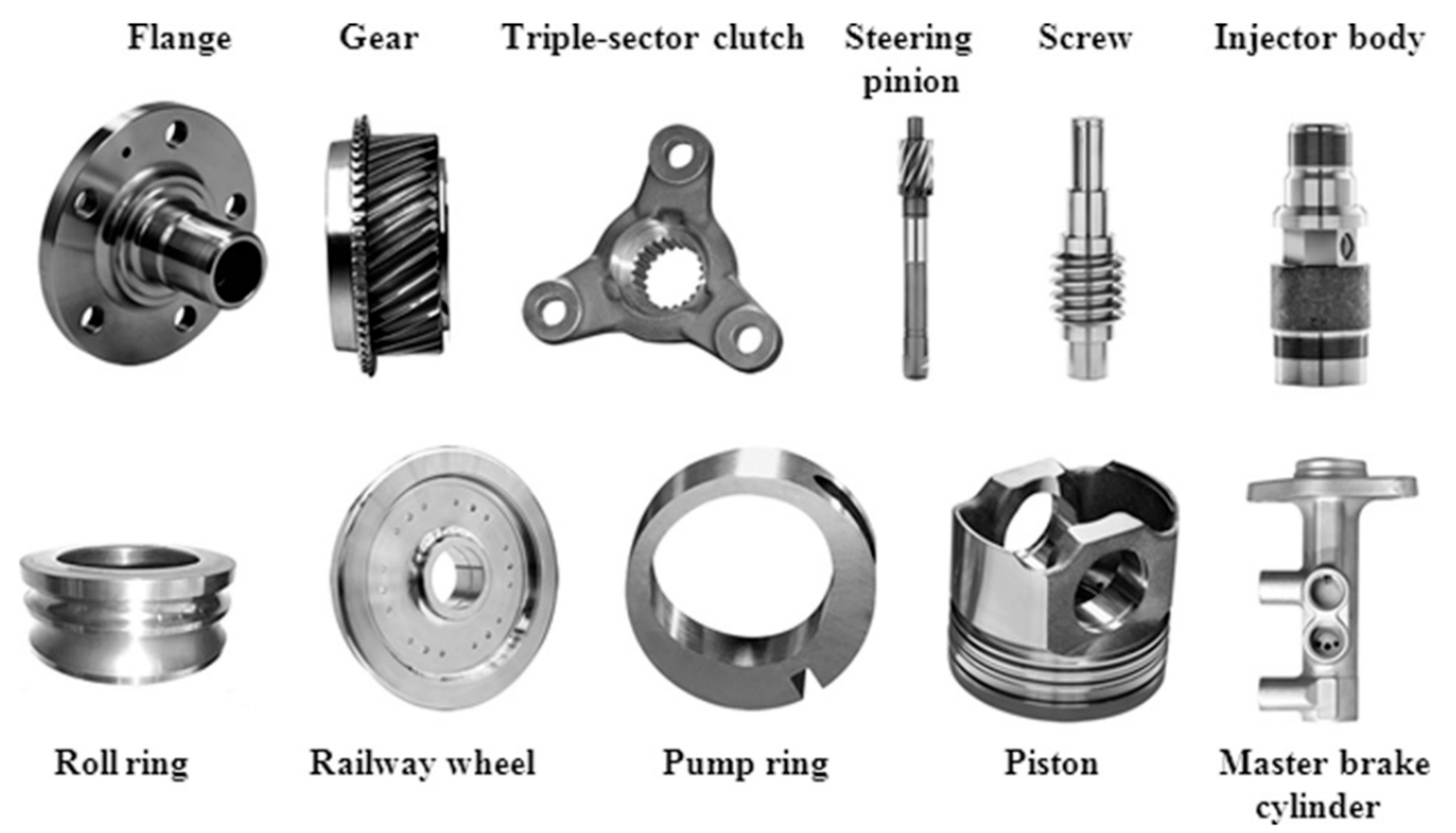
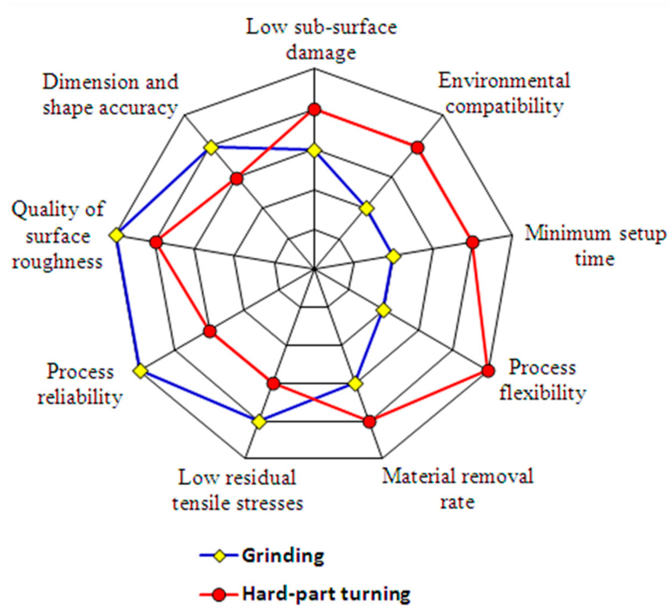
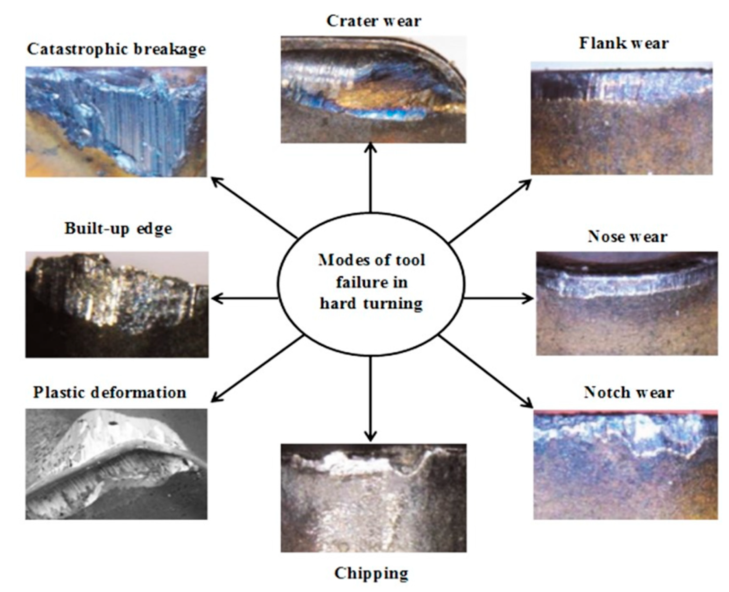
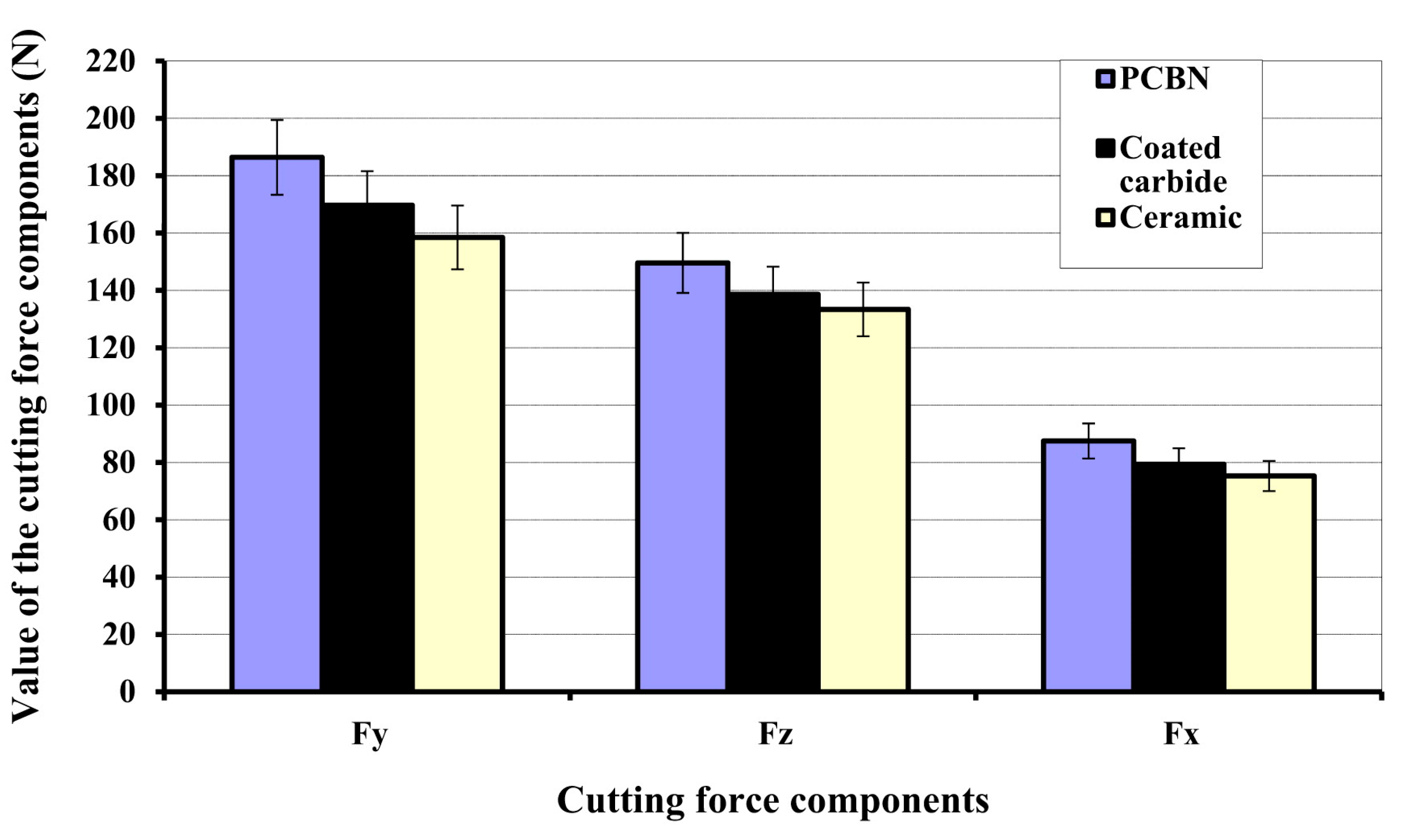
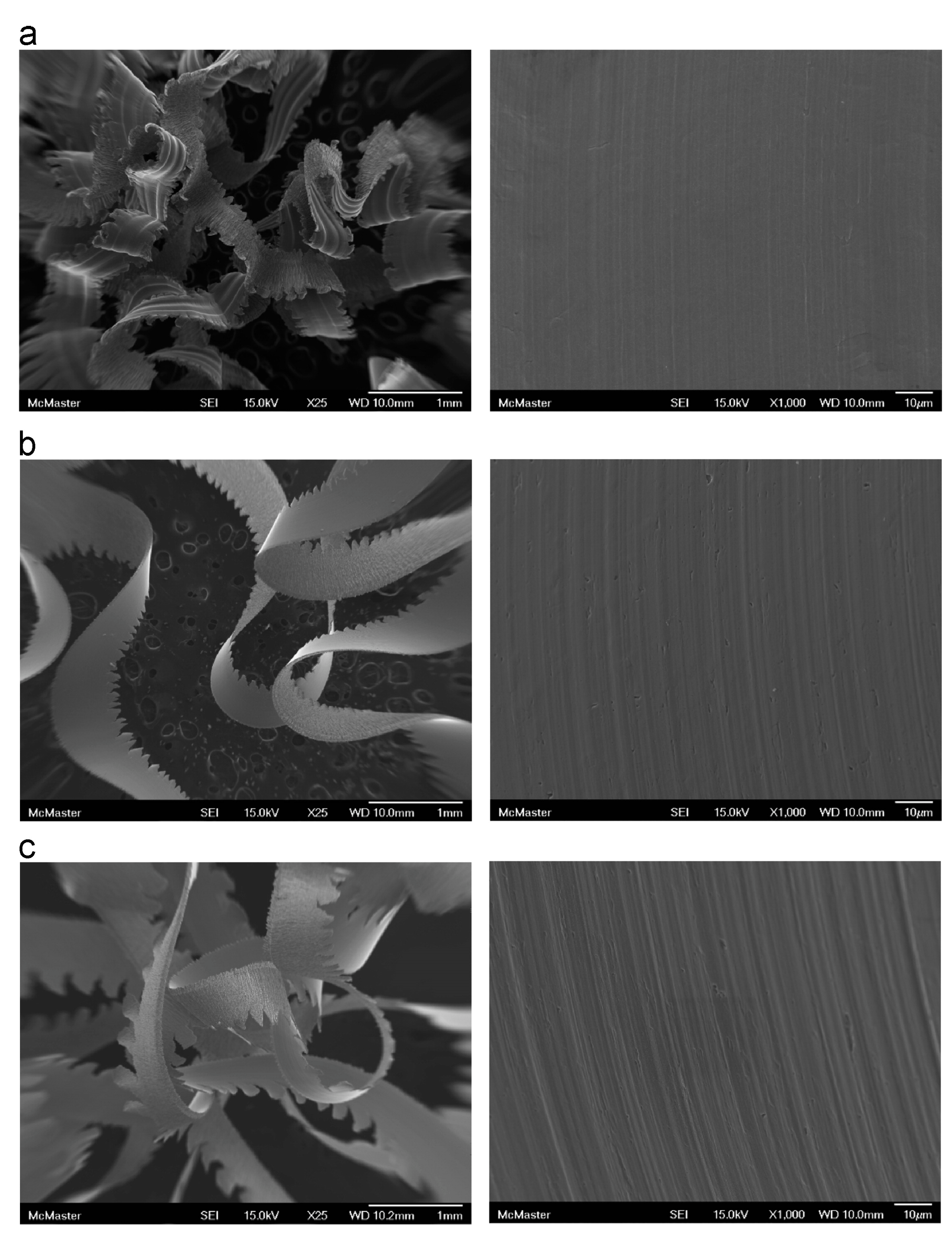
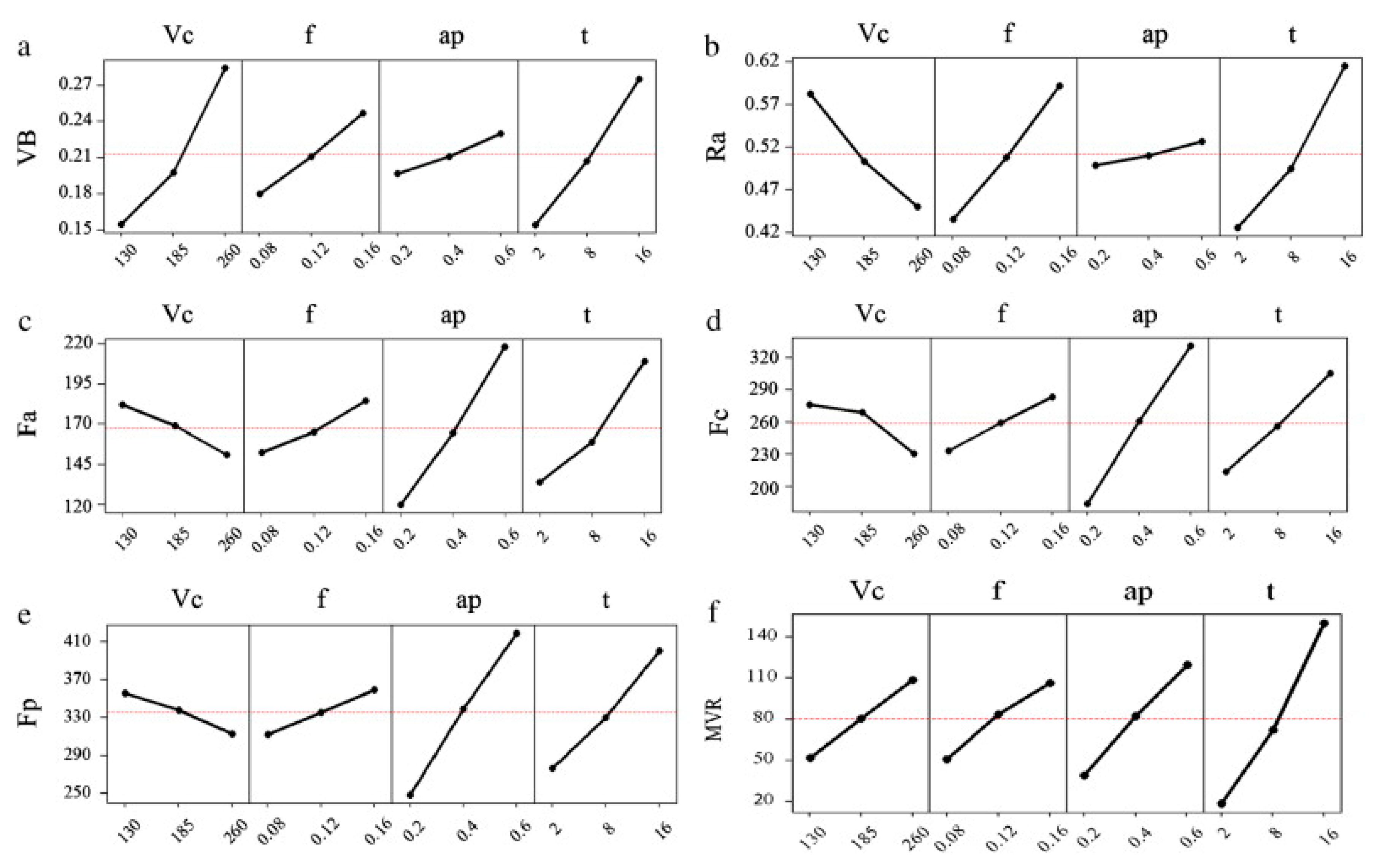
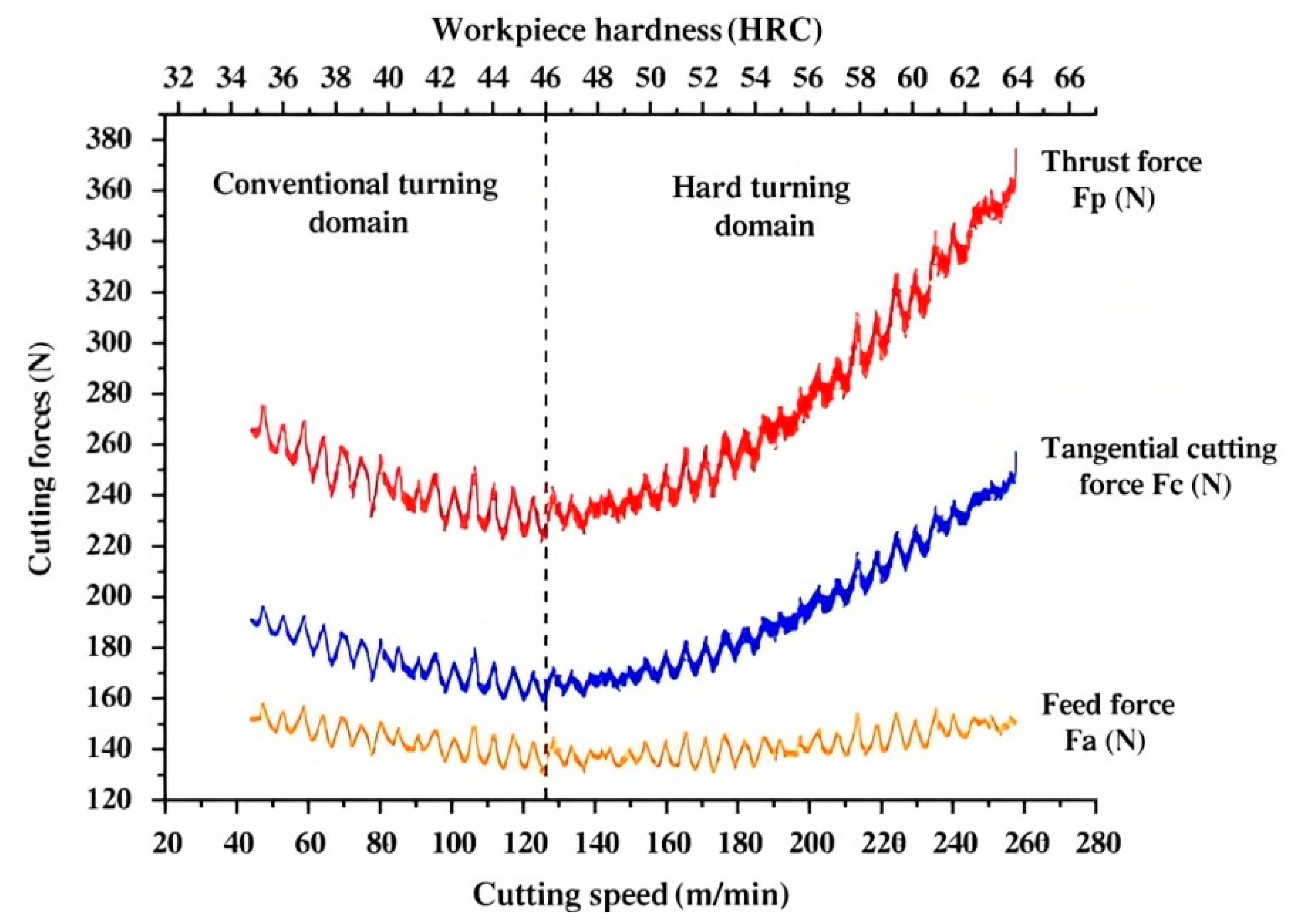
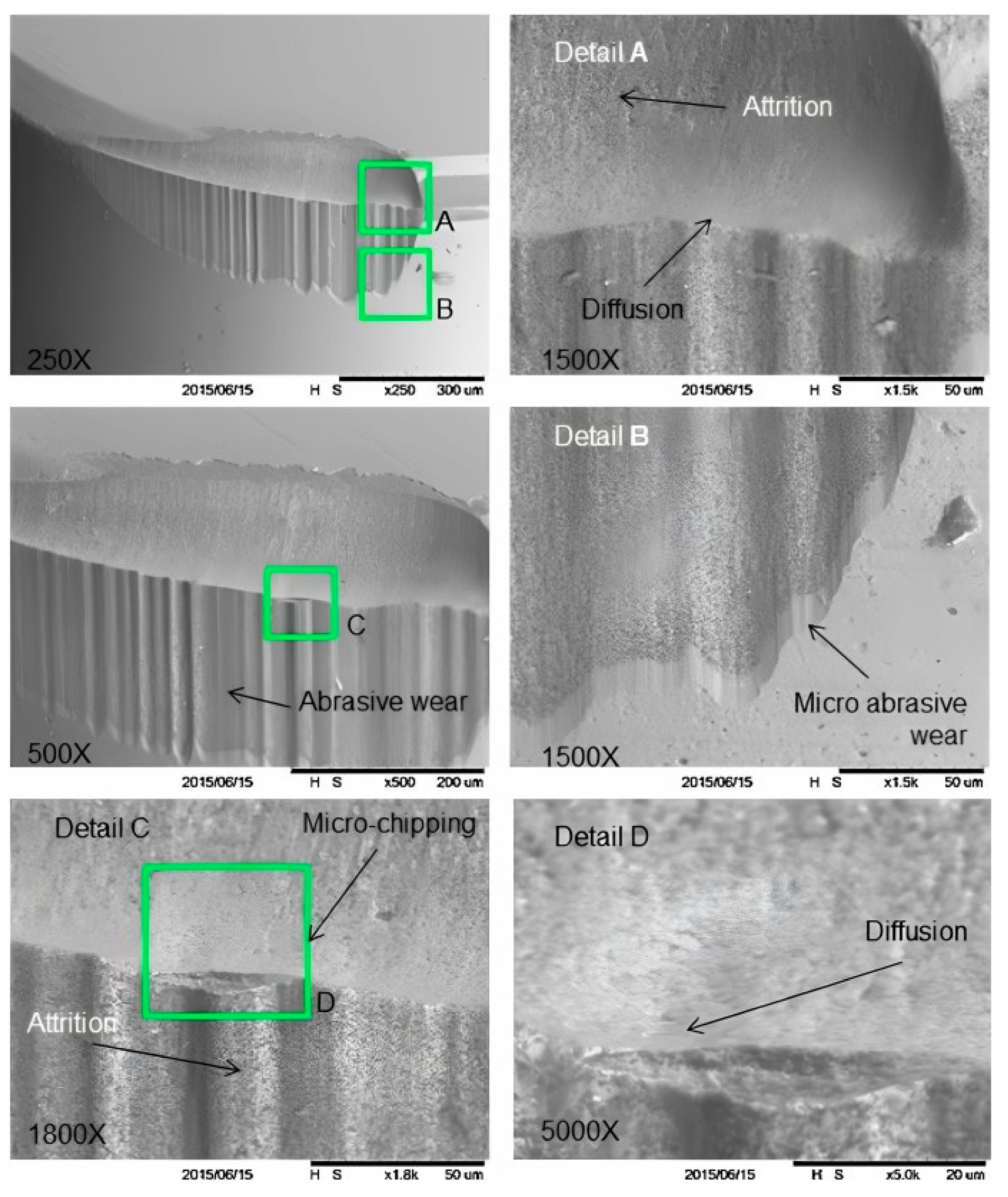
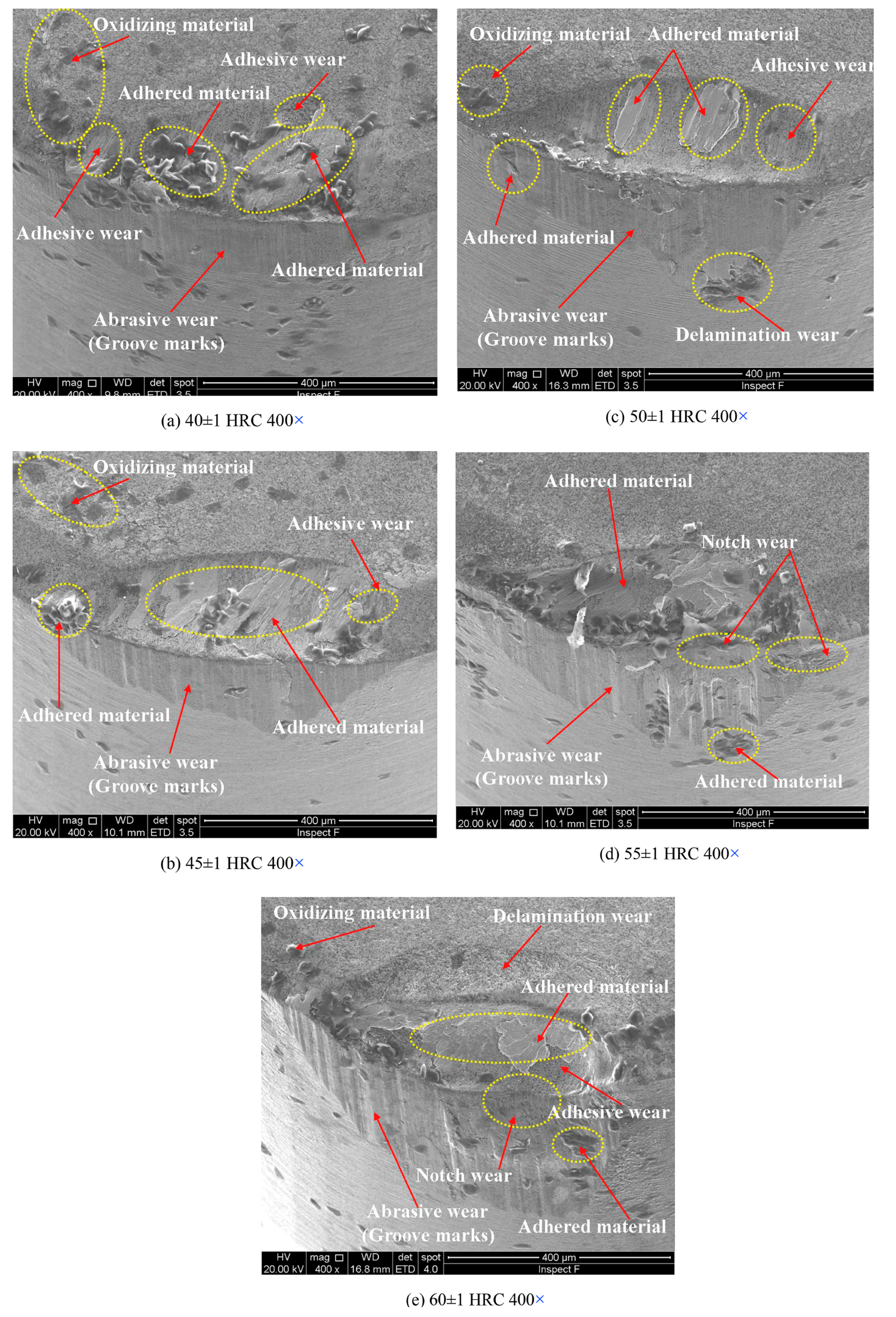
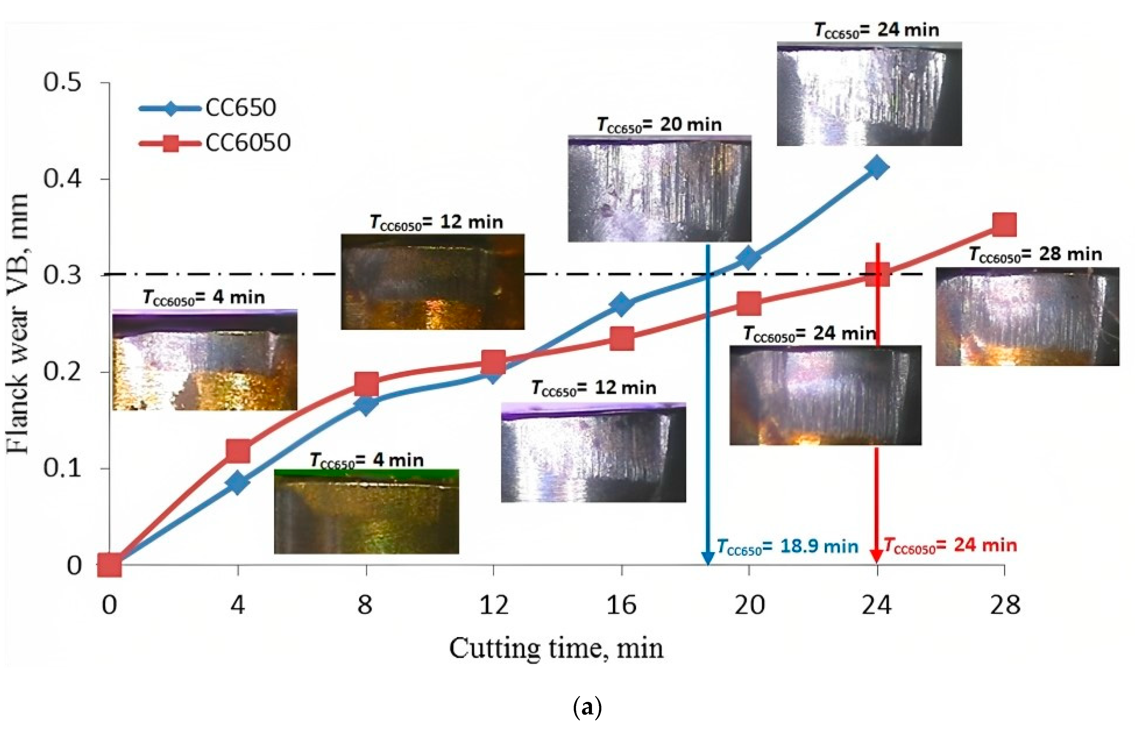
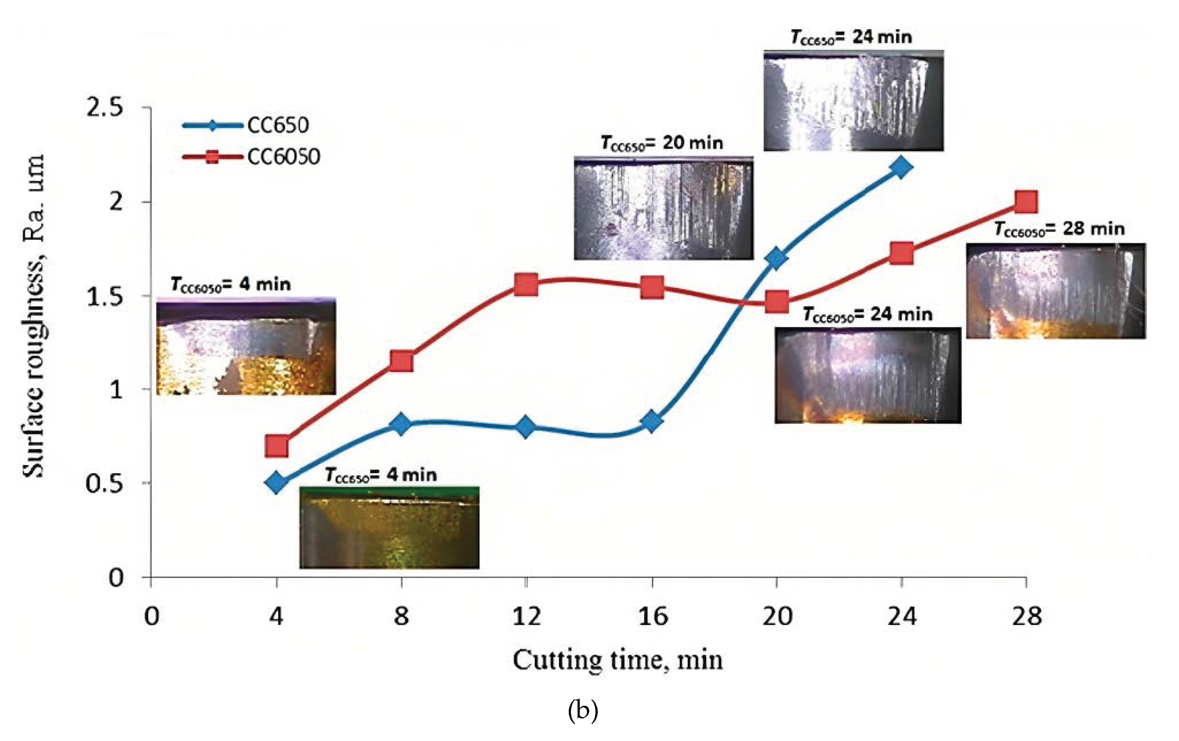
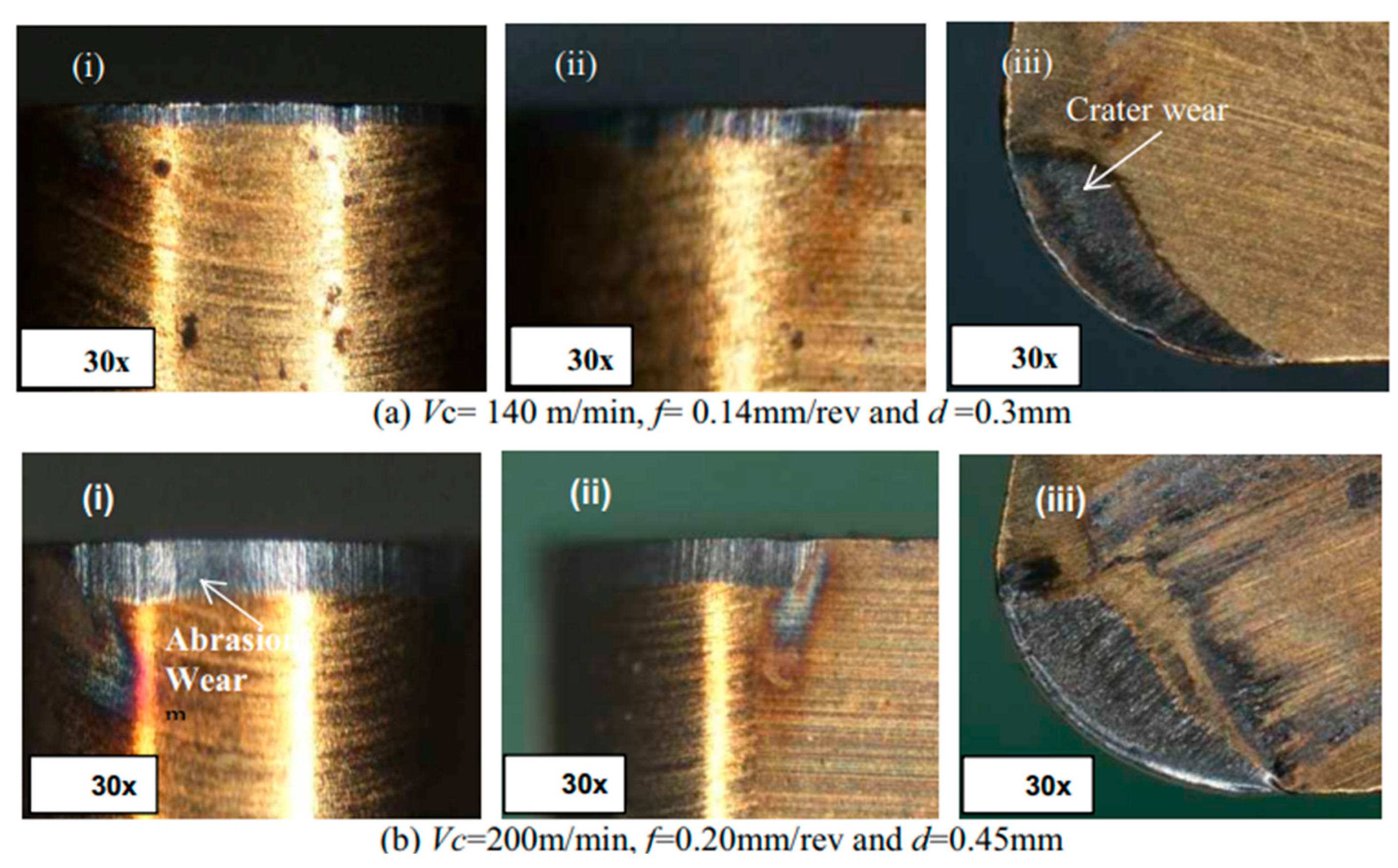
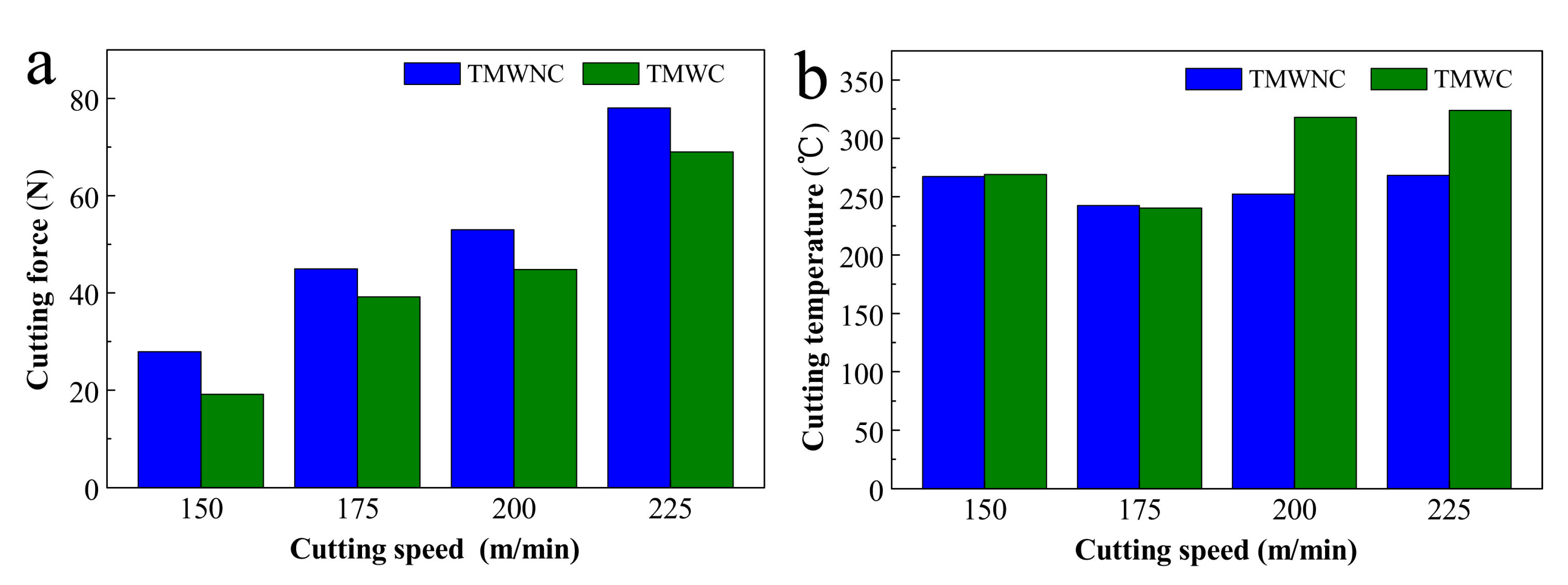
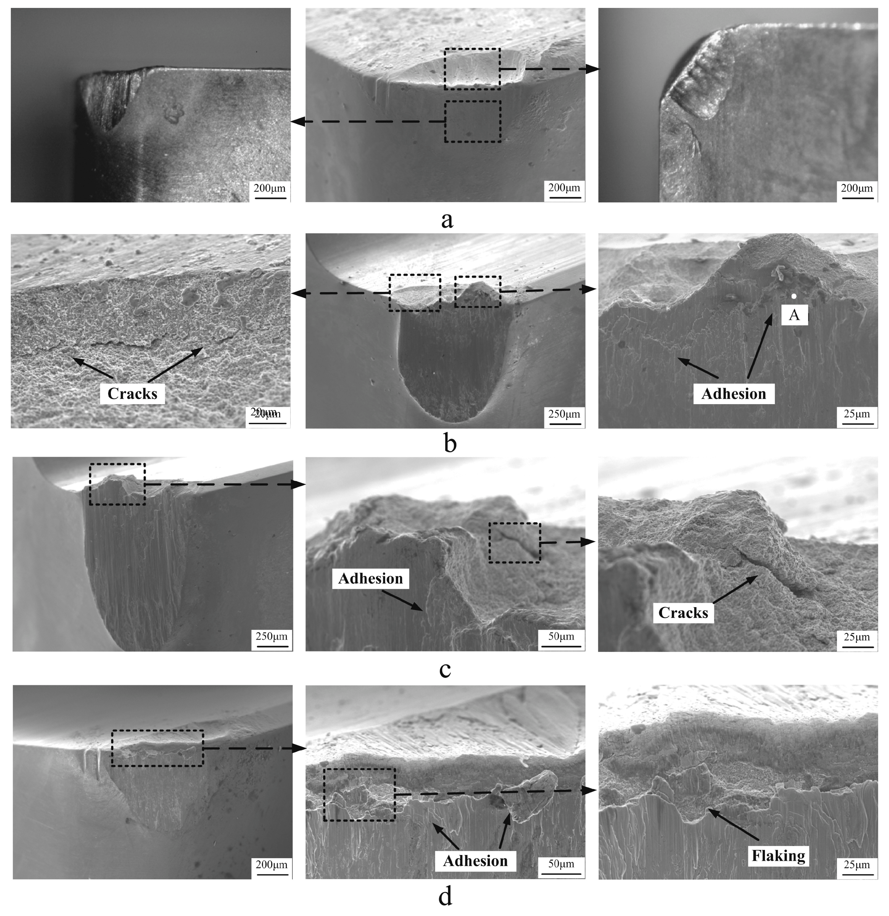
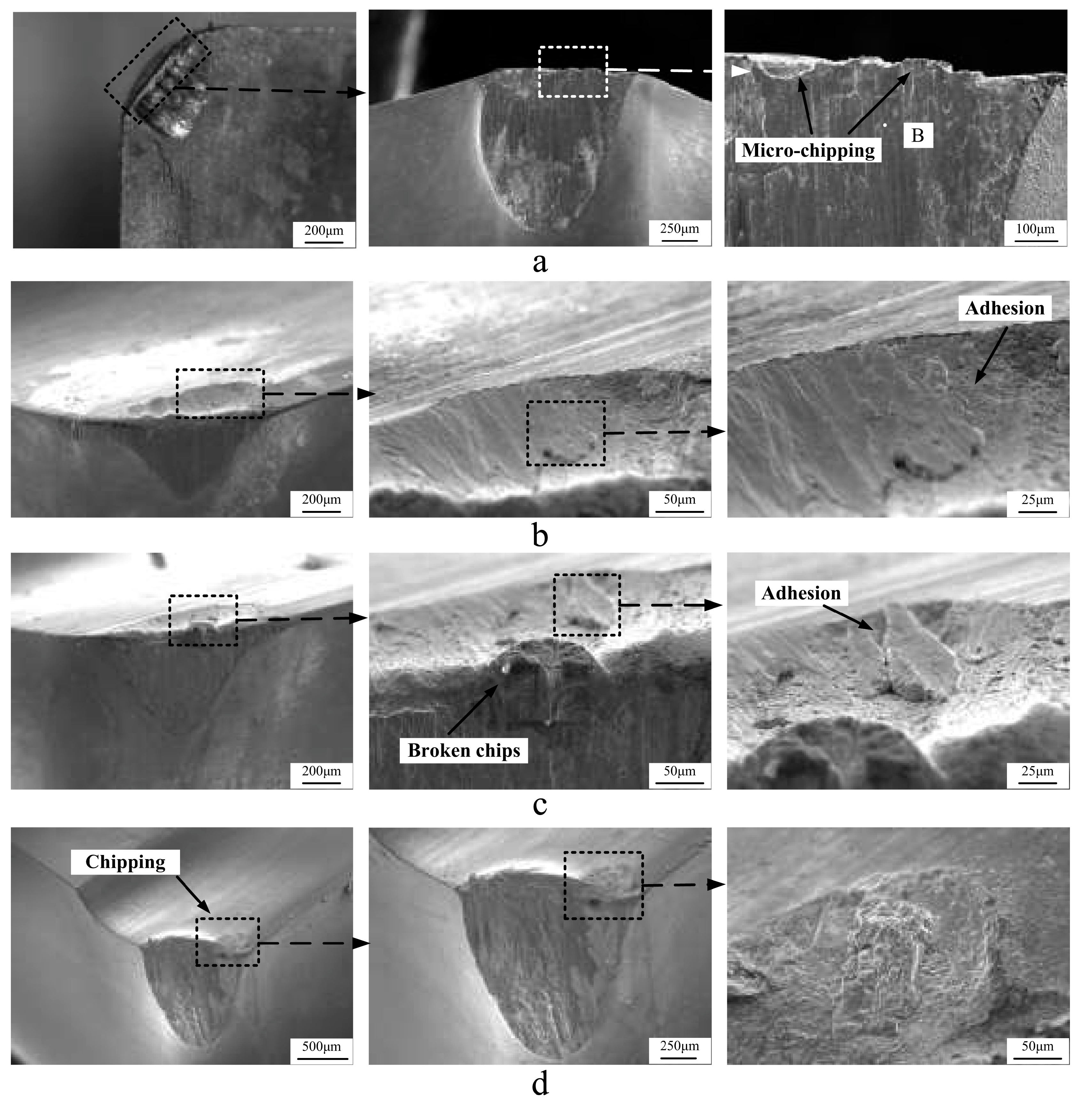
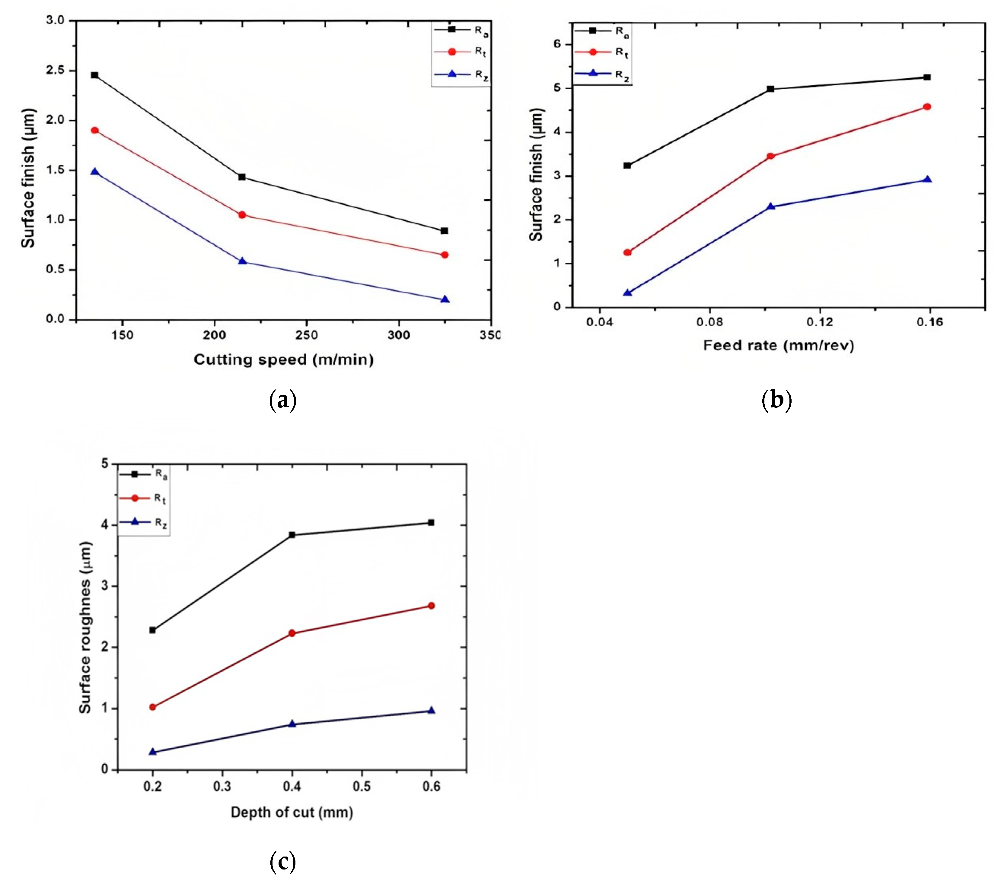
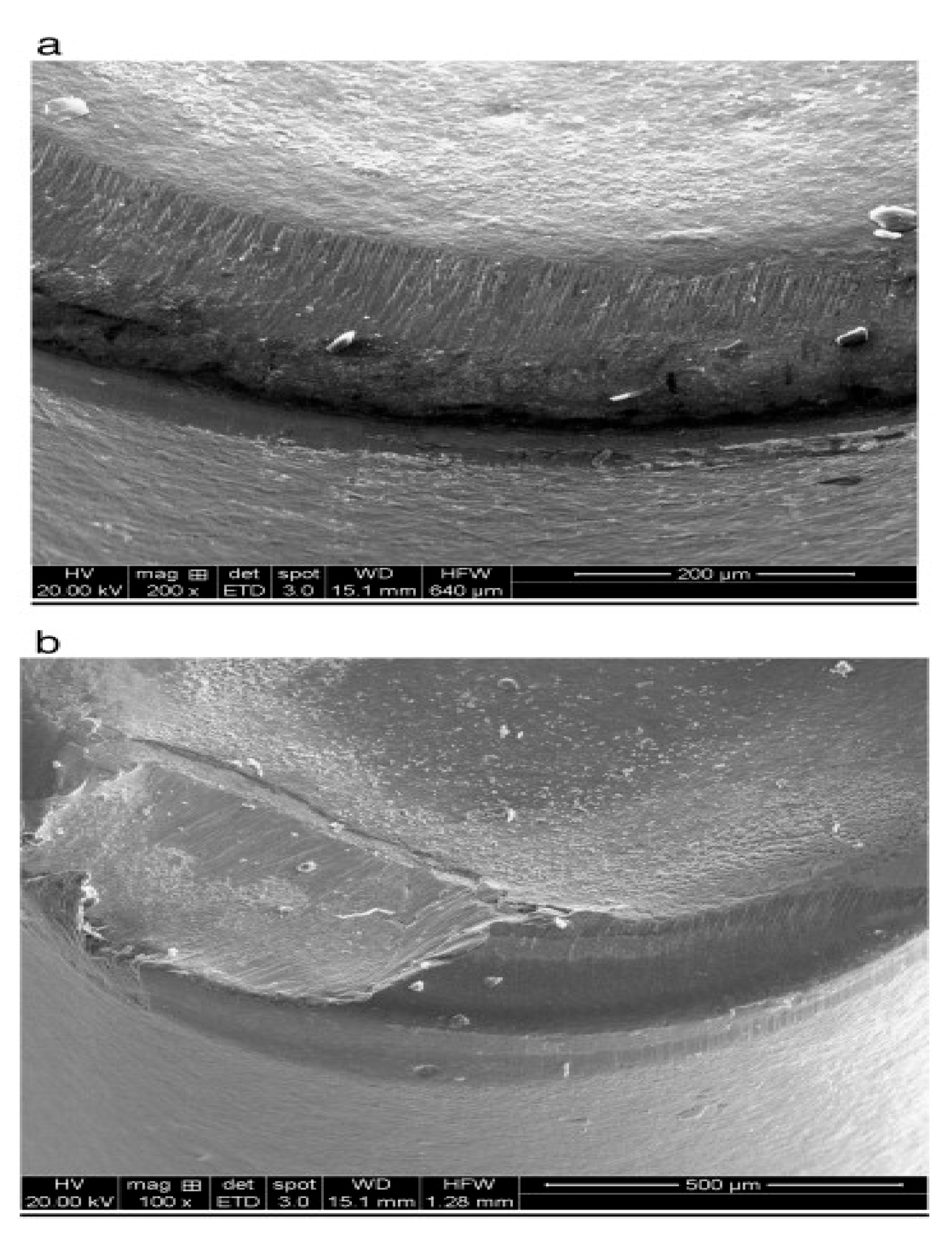
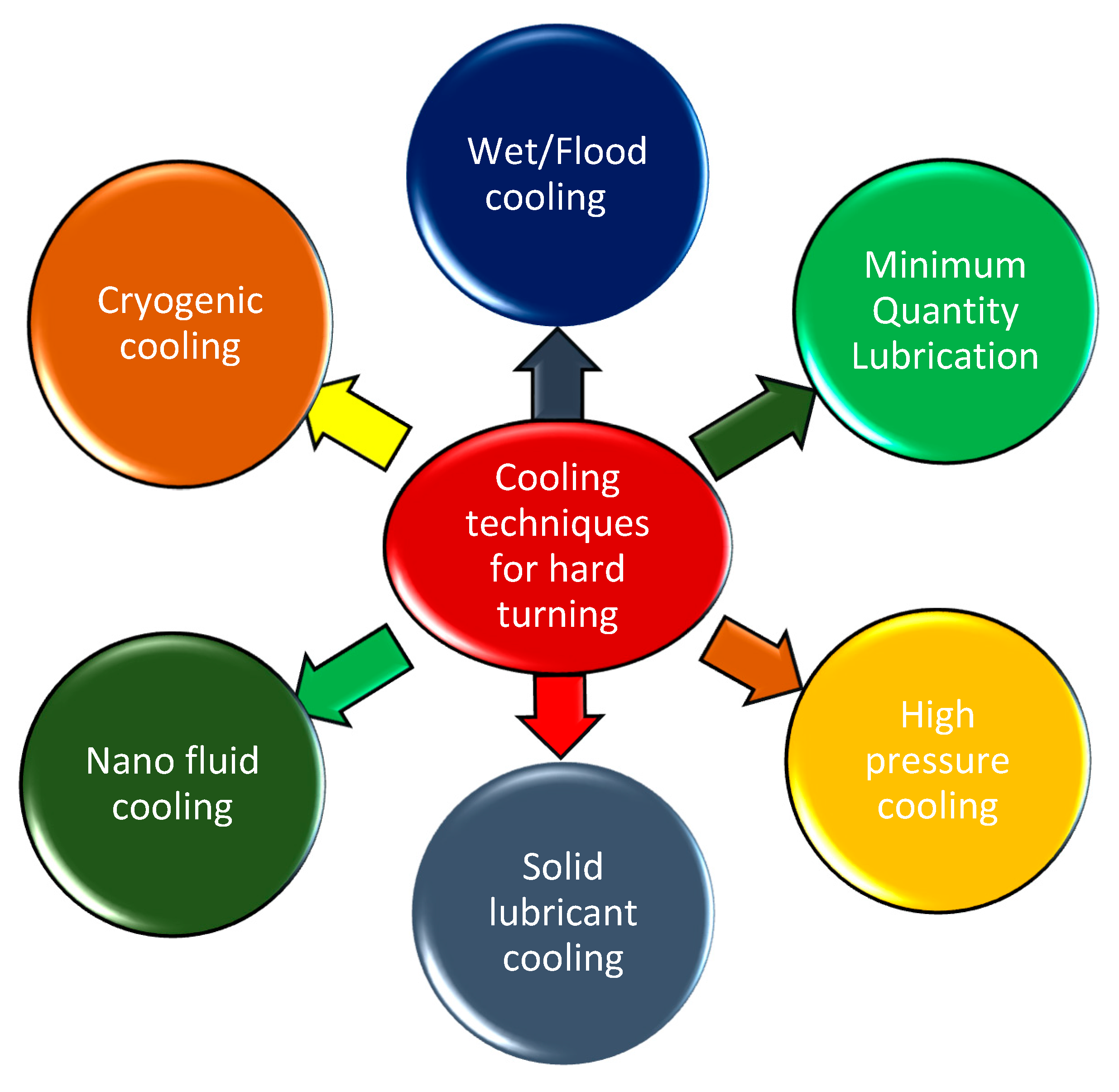
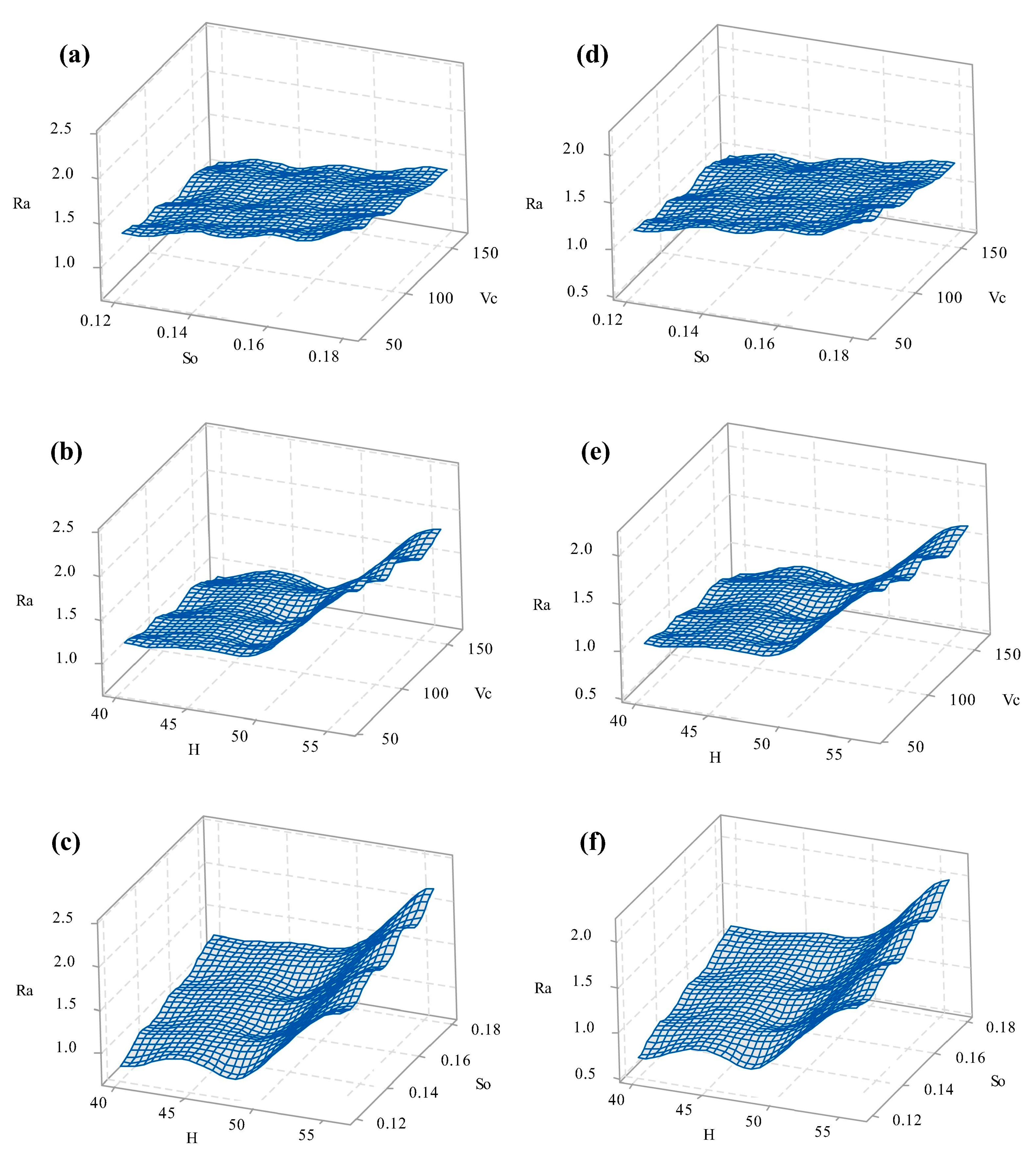
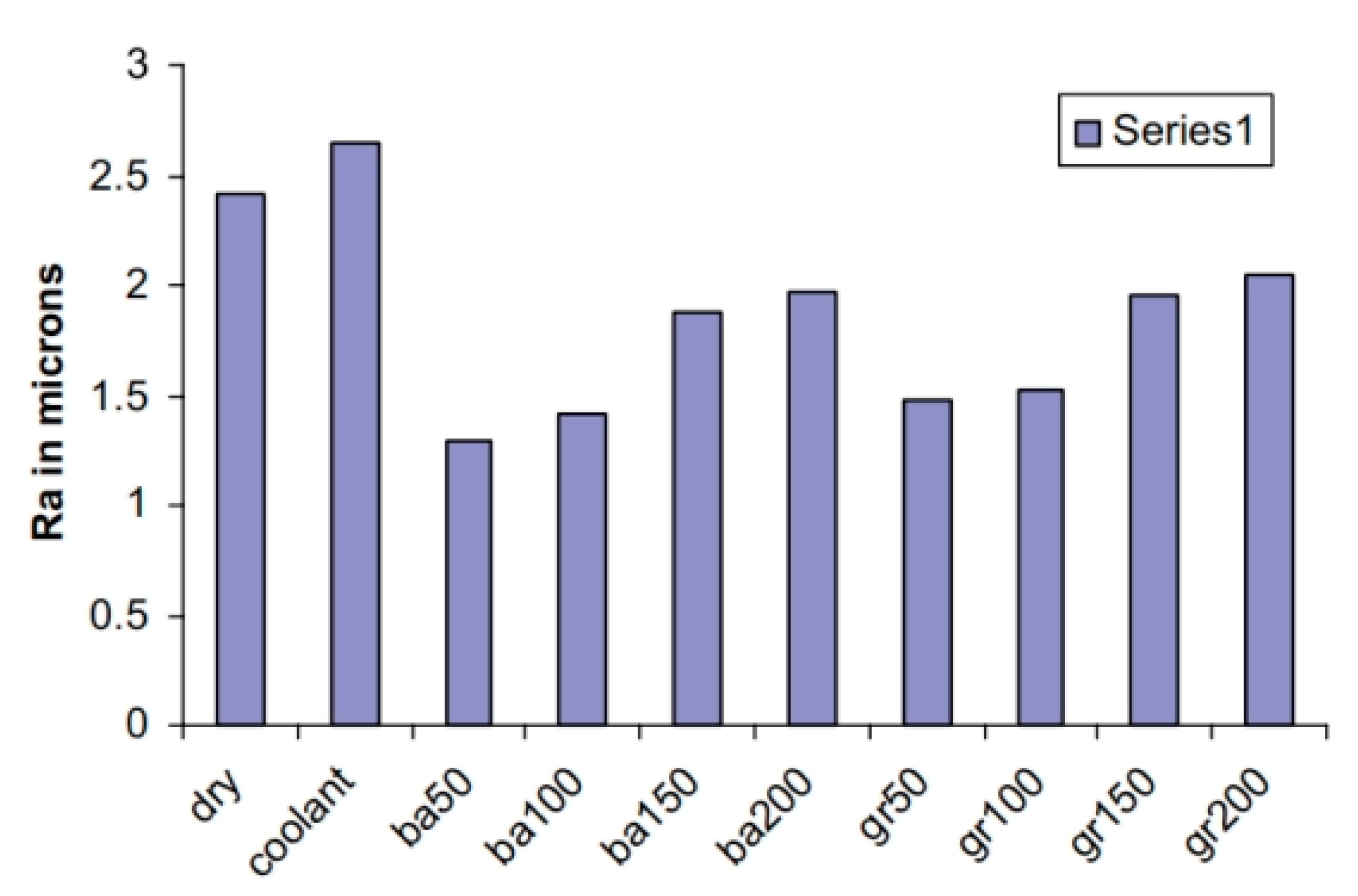
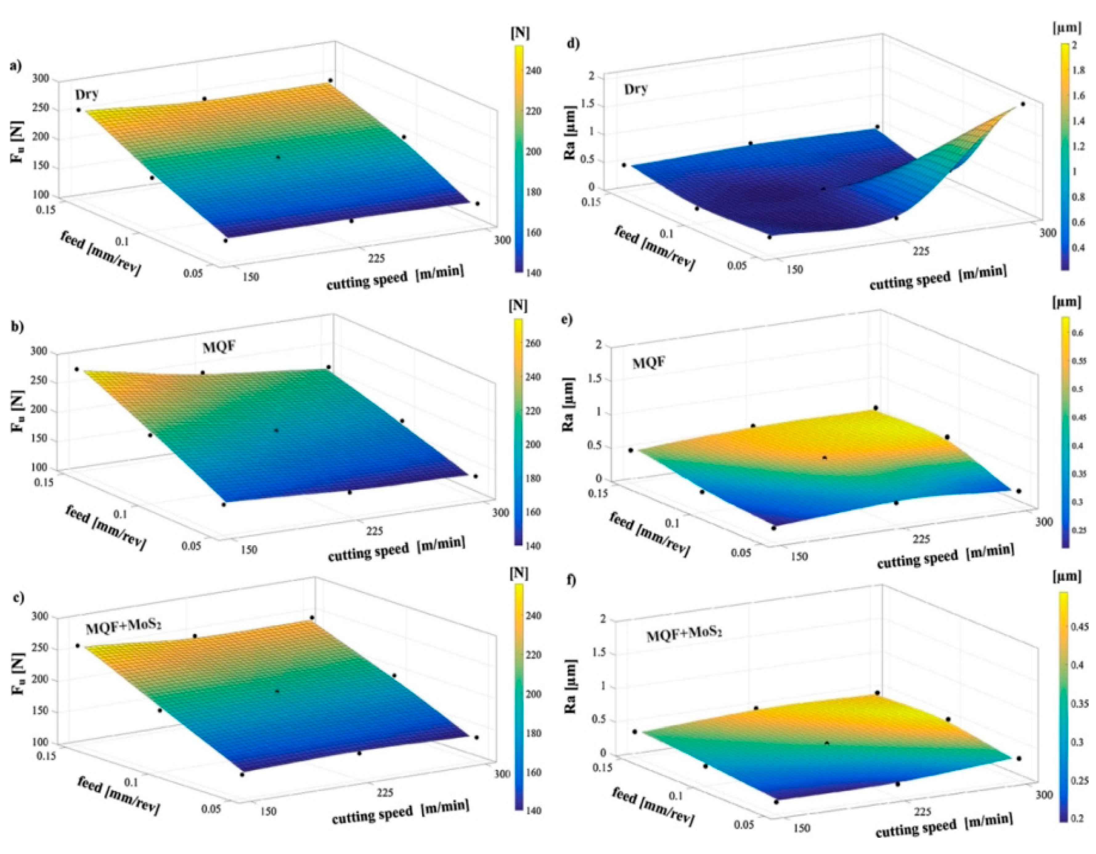
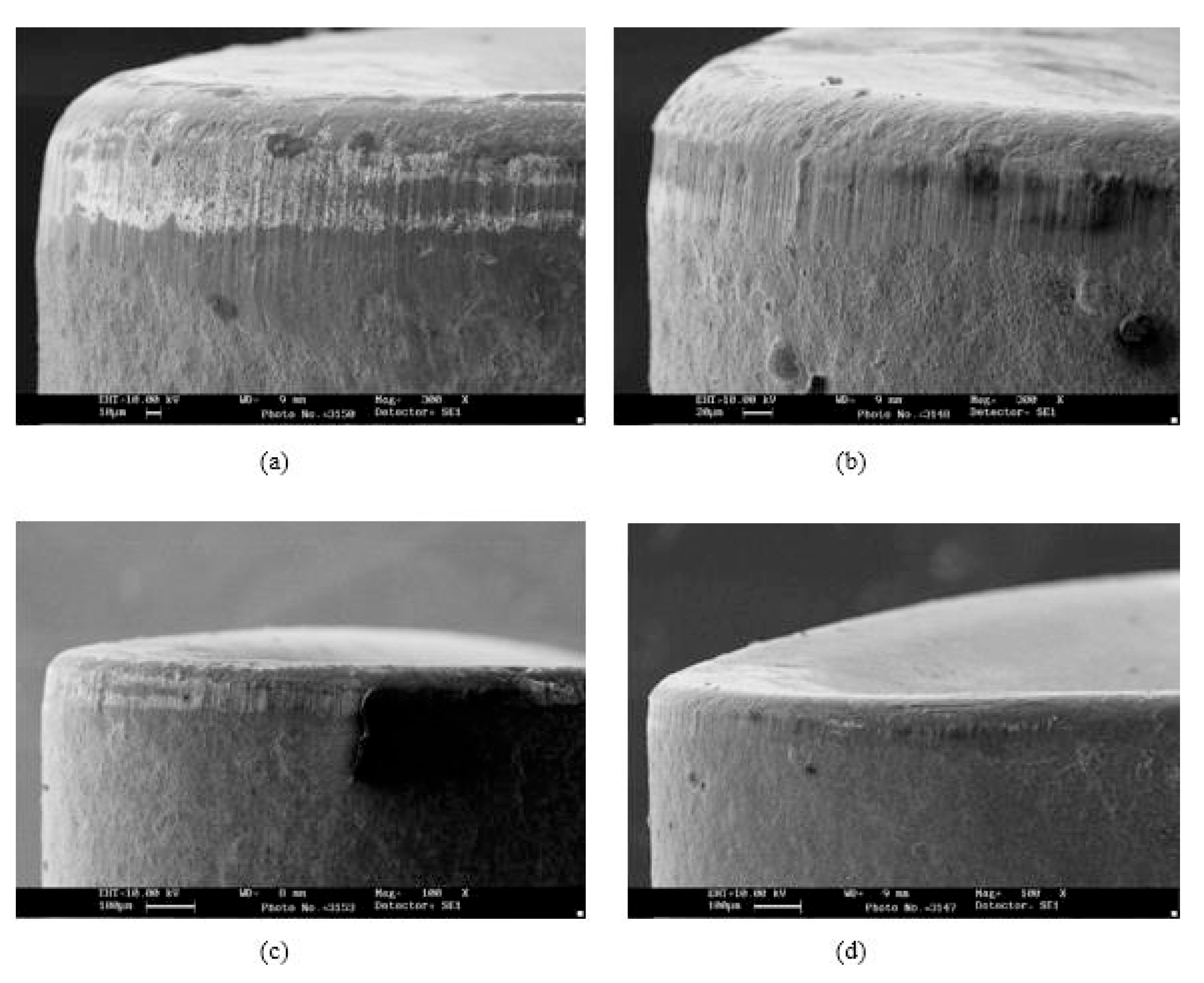
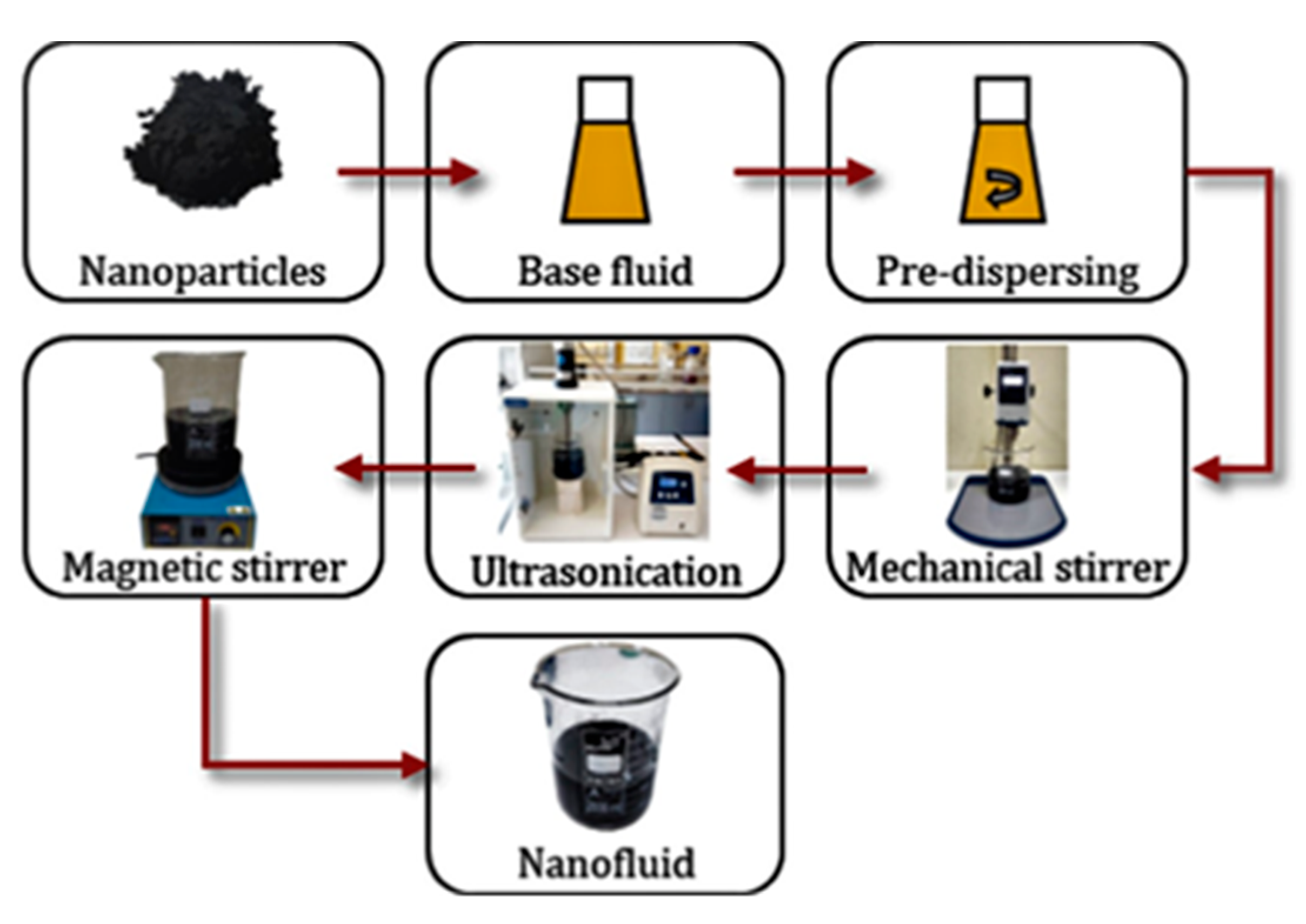
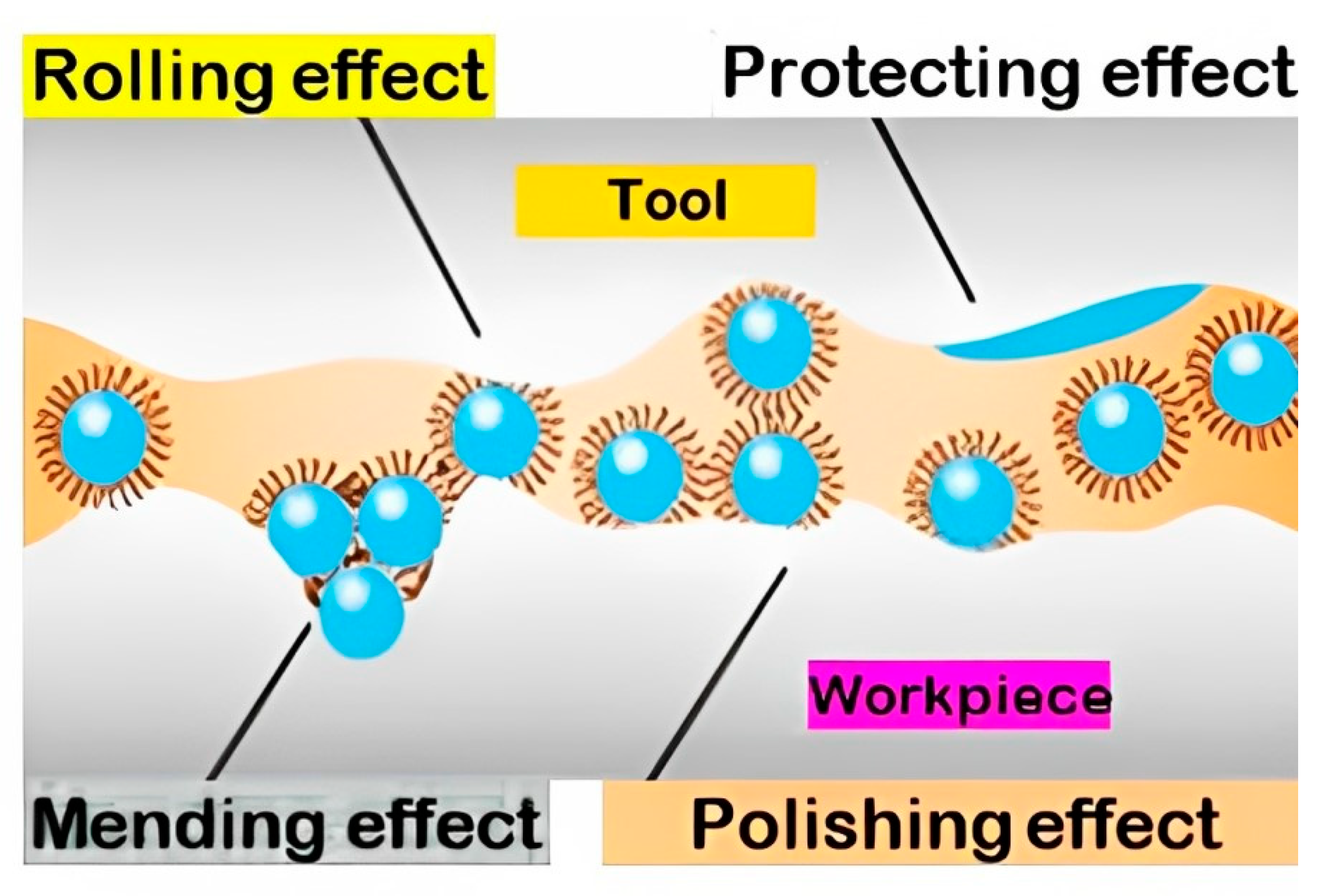
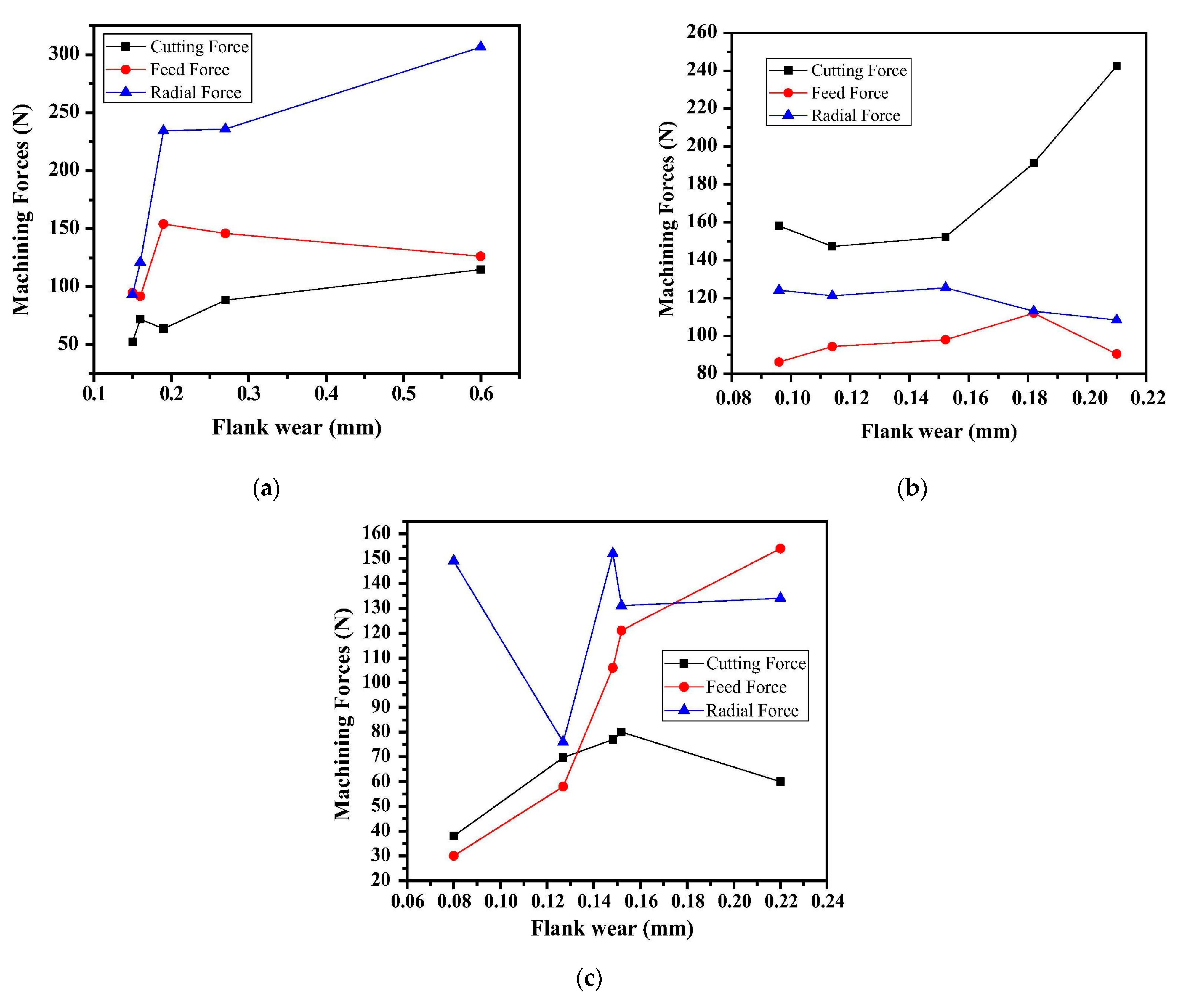
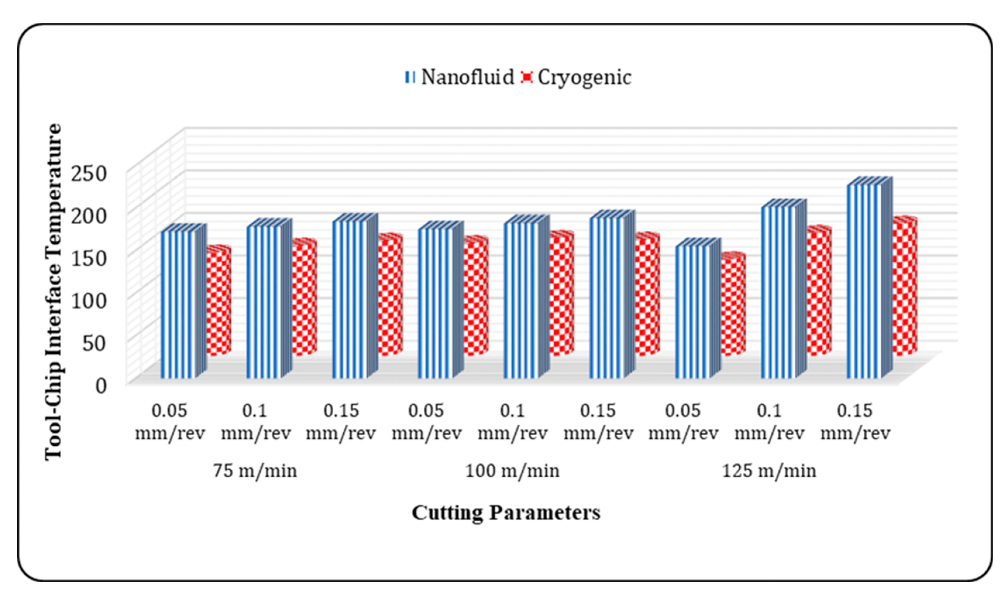
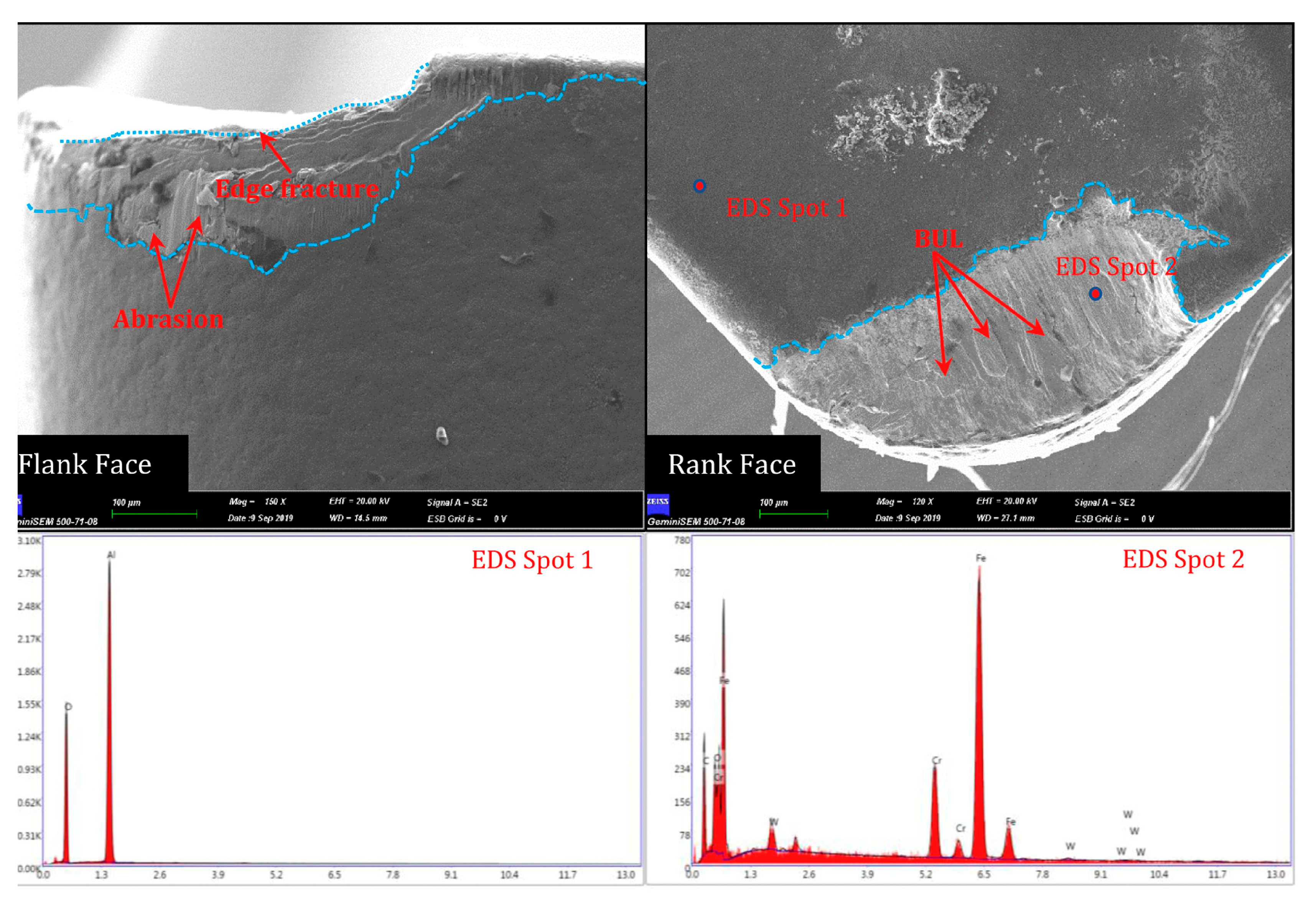
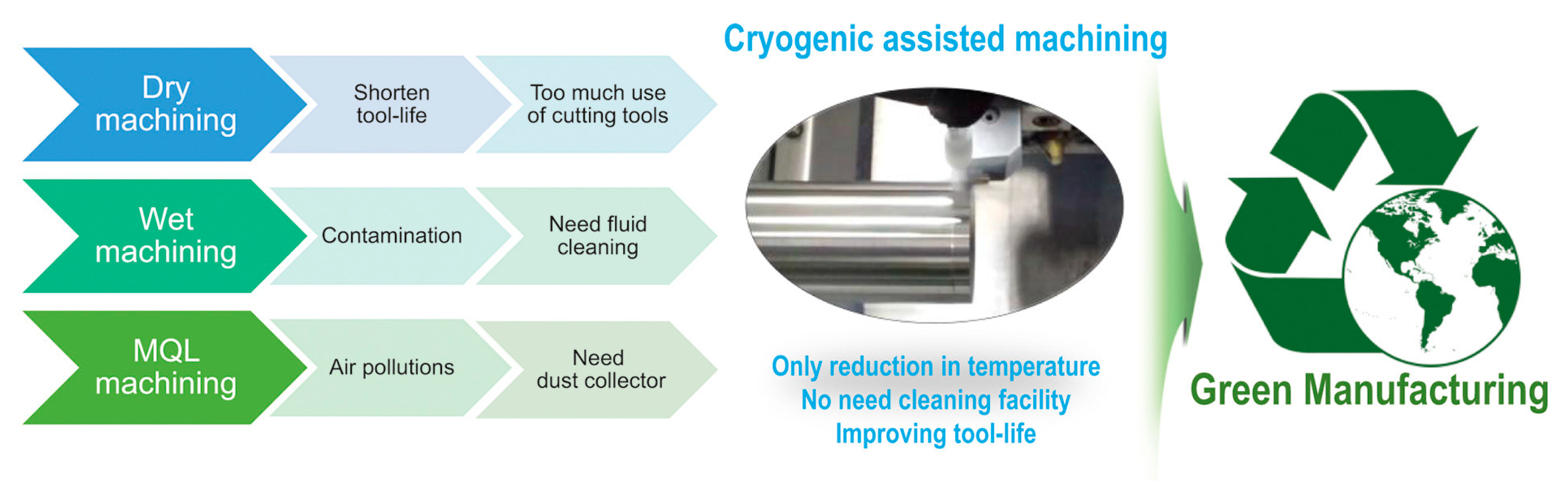
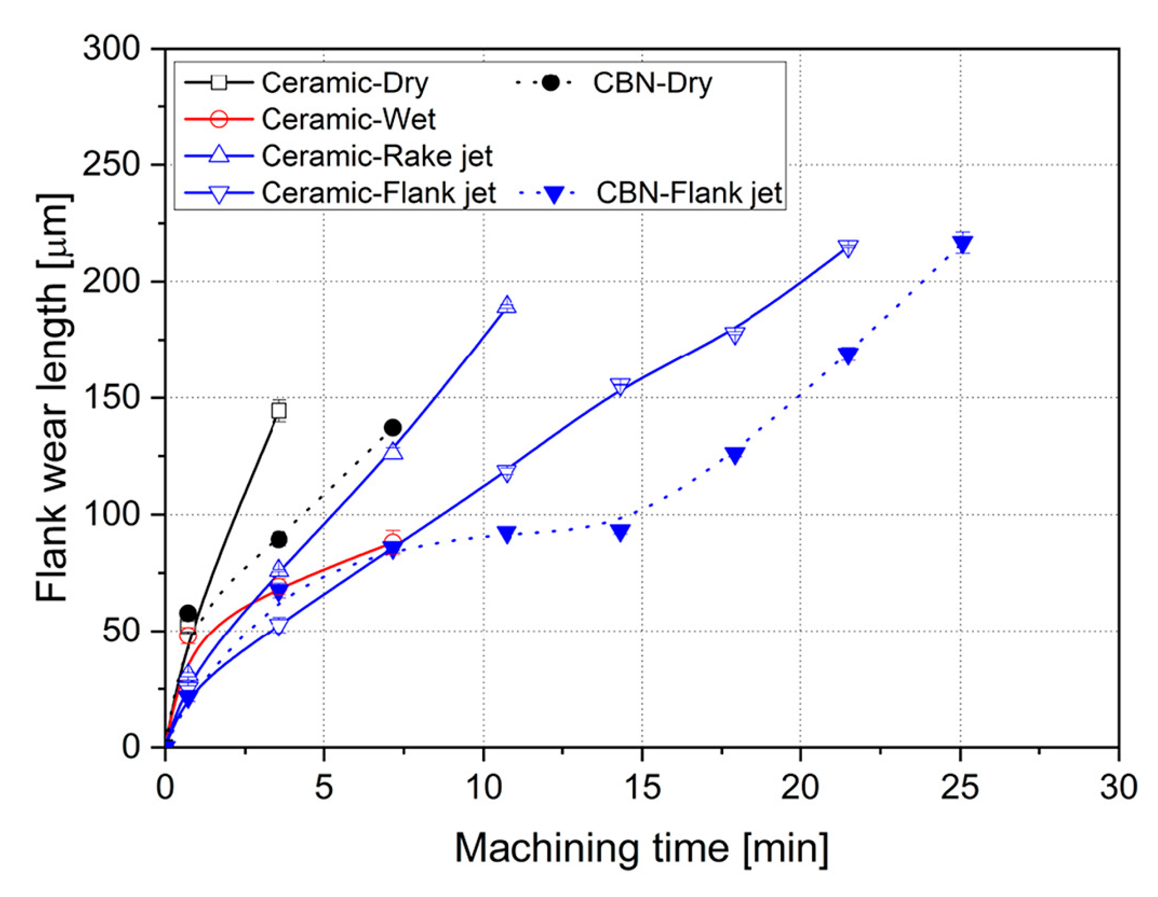
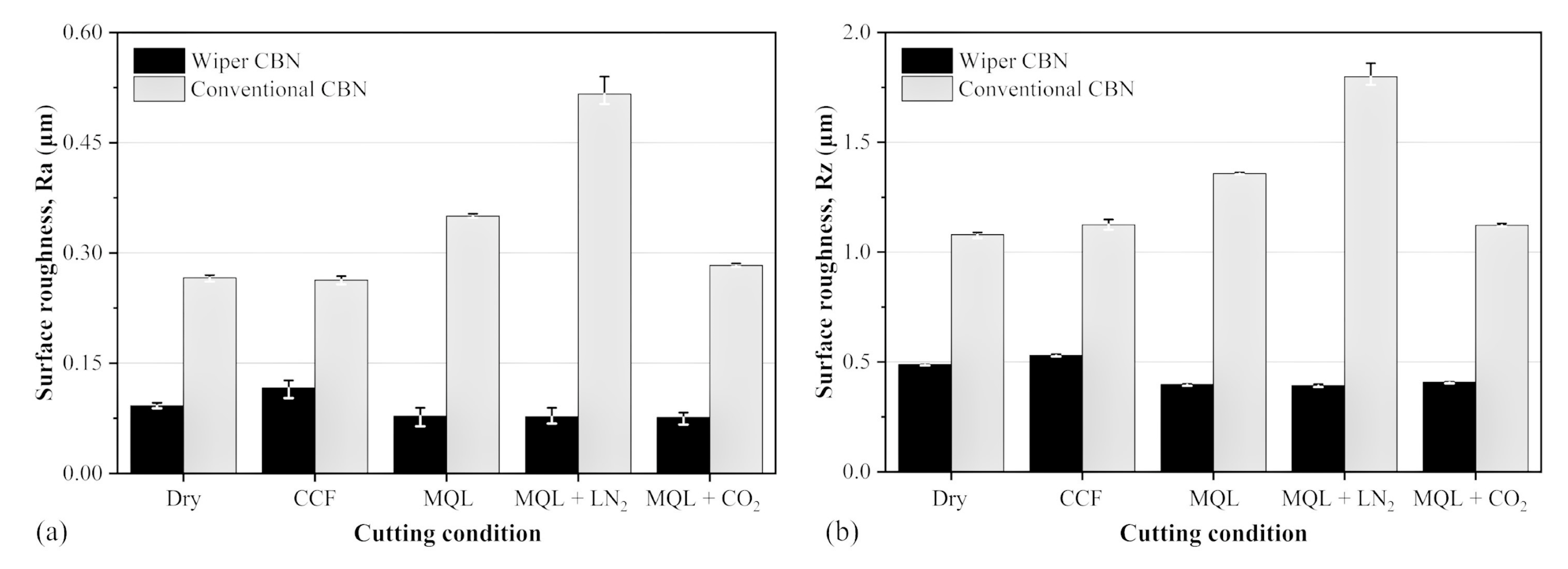
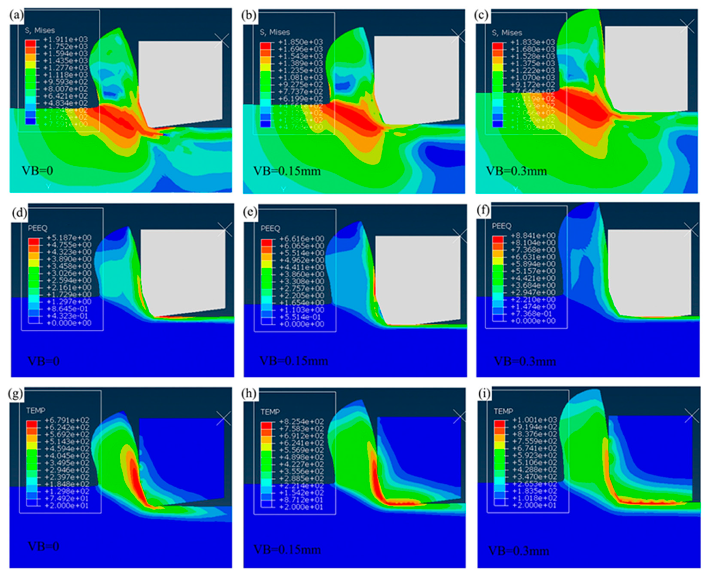
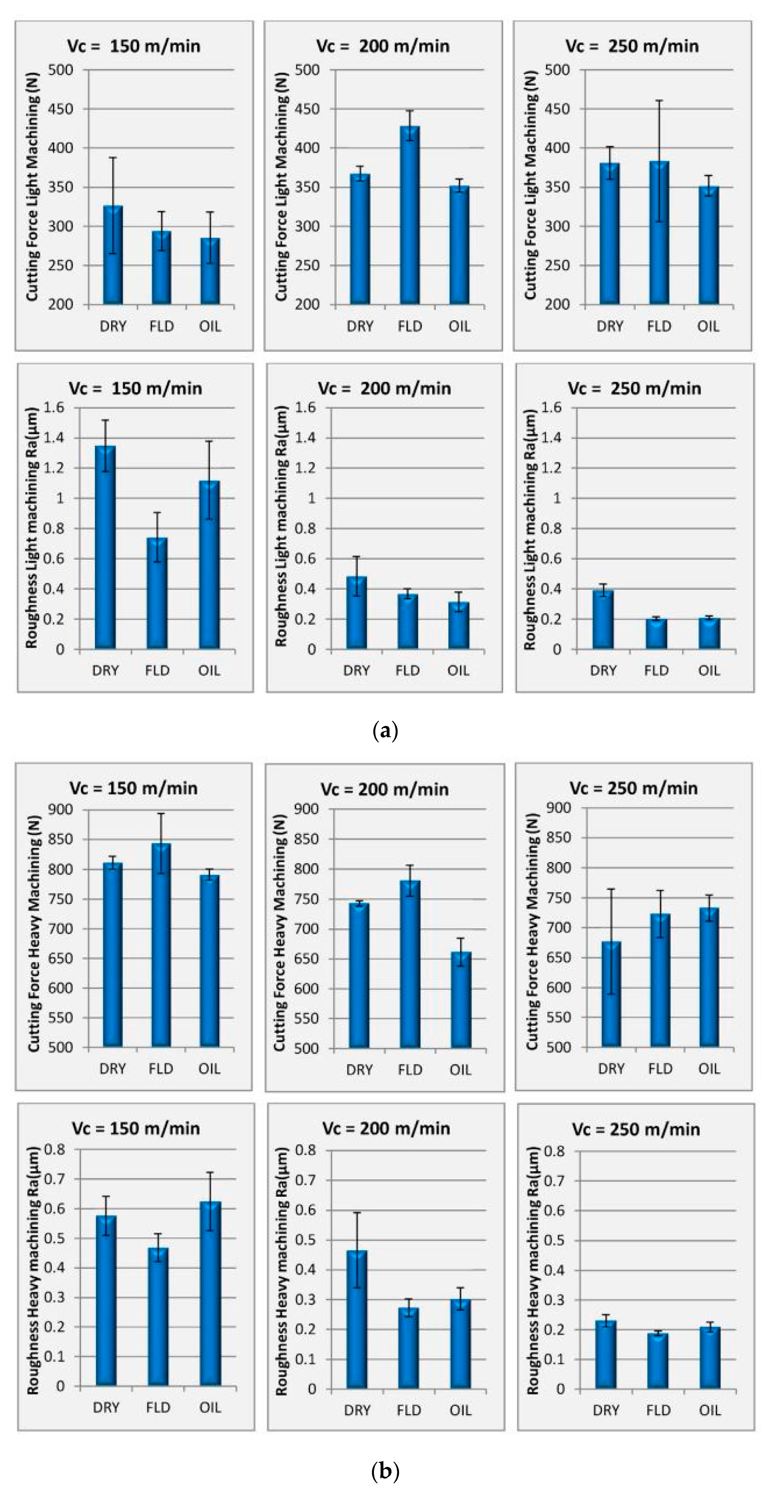
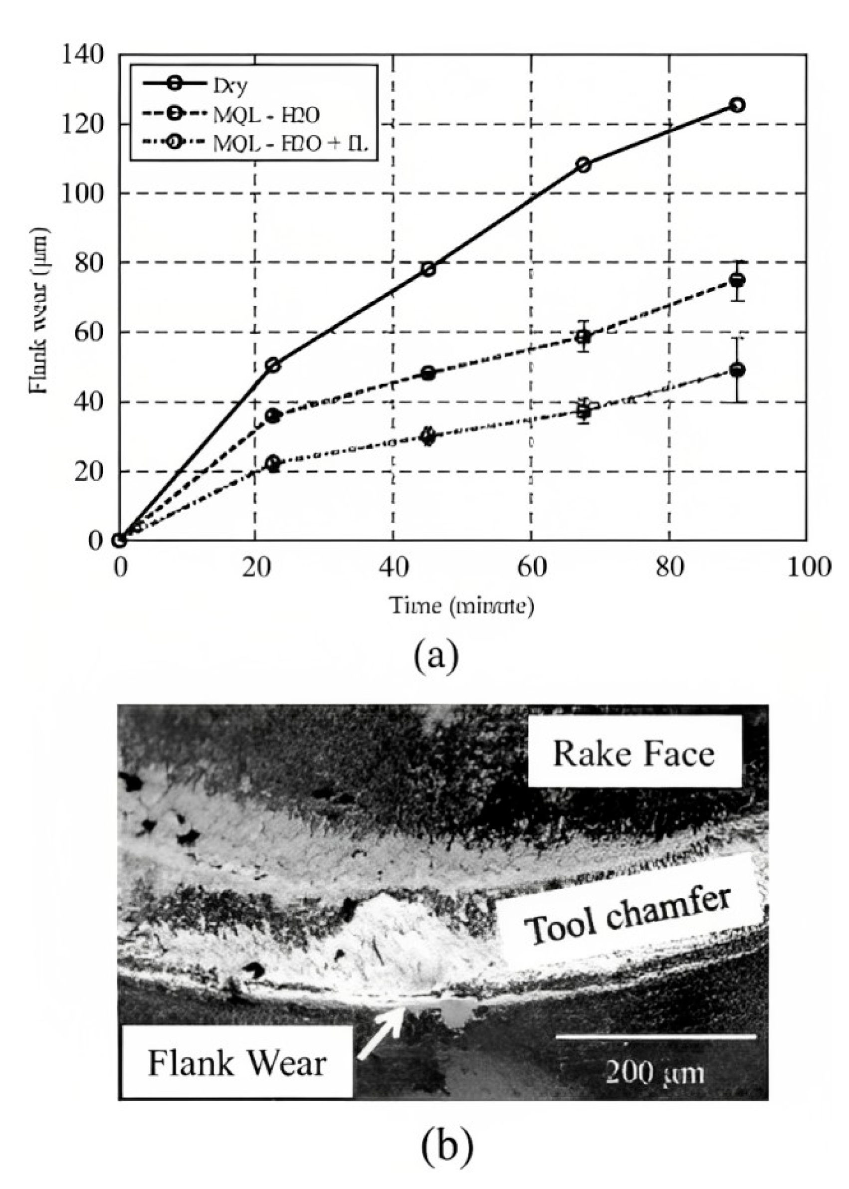
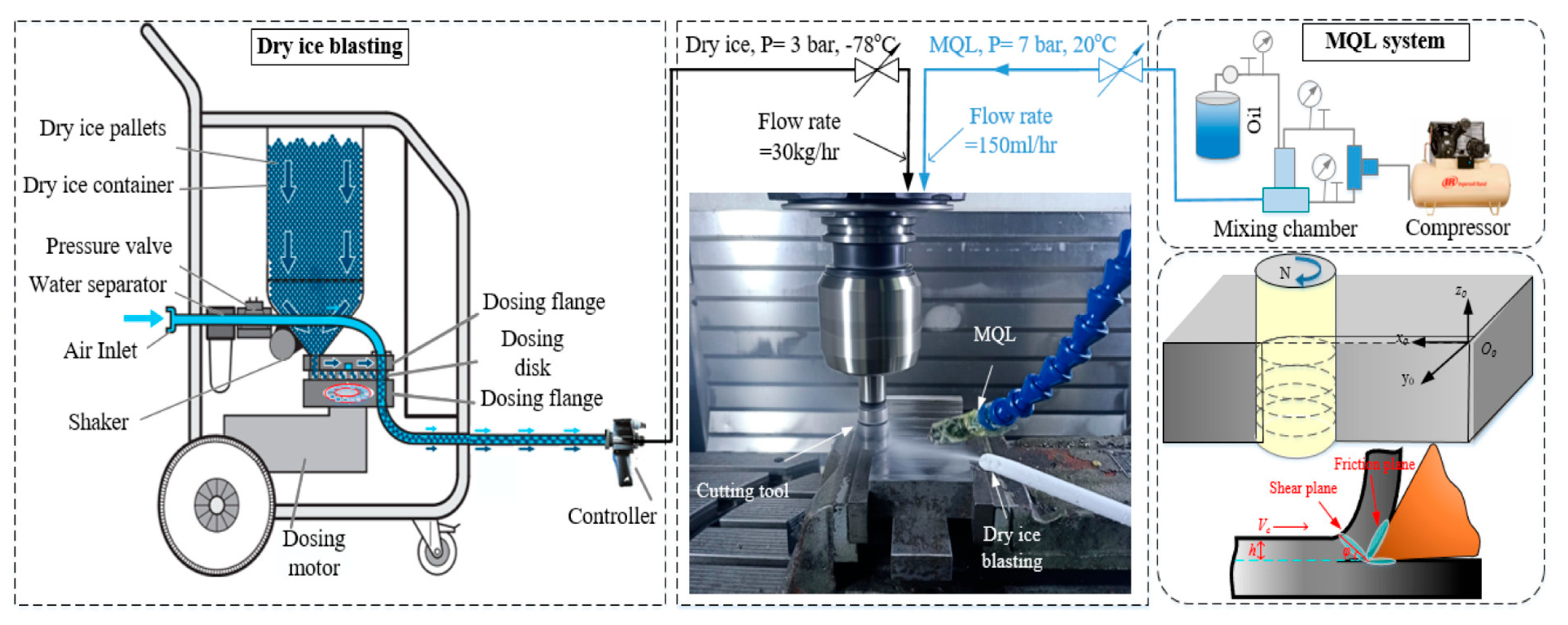
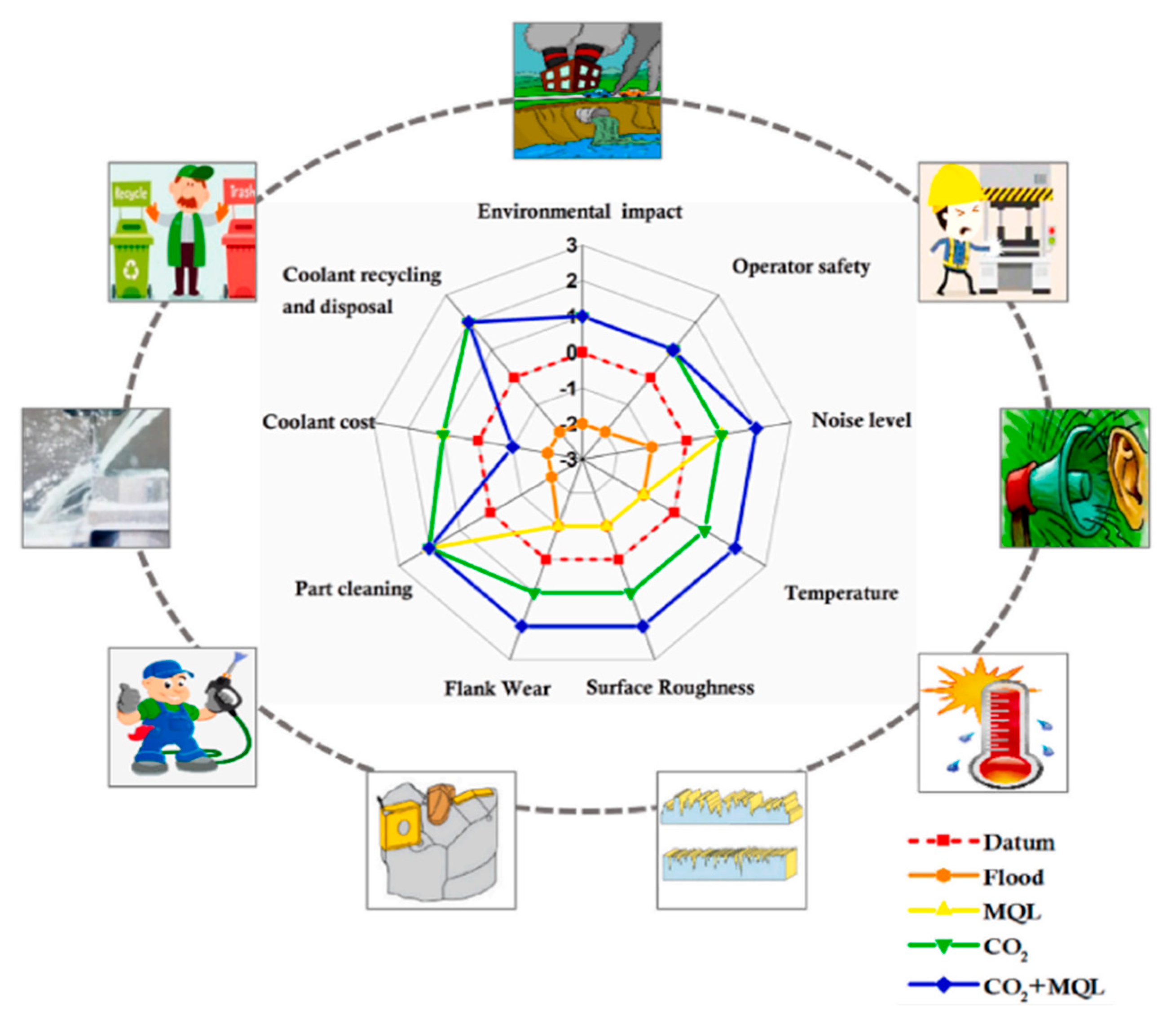
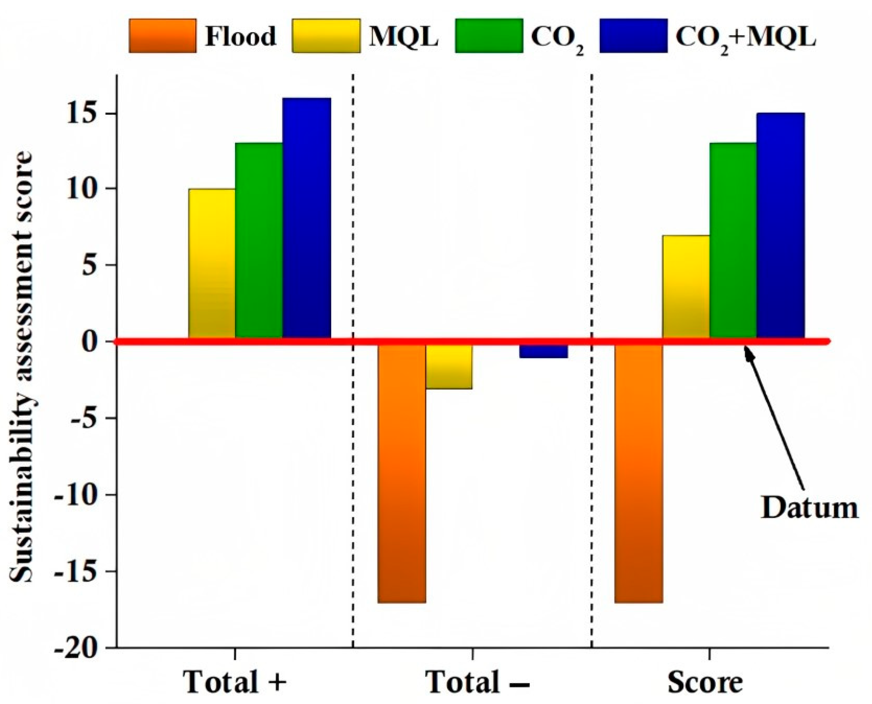
Table 1.
Details of used cutting tool and cutting parameters in hard turning.
| Ref. | Materials with Hardness | Cutting Tool | Cutting Parameters | Responses Studied | ||
|---|---|---|---|---|---|---|
| Vc (m/min) | f (mm/rev) | ap (mm) | ||||
| [28] | AISI 52100, AISI D2, AISI H13, AISI 4340 (44, 48, 52, 58 HRC of each materials) | CBN | 140, 180, 240 | 0.15, 0.3, 0.45 | 0.2 | cutting force |
| [29] | AISI D2 steel (62 HRC) | PCBN | 140, 270, 350, 500 | 0.05, 0.1, 0.2 | 0.2, 0.4, 0.6 | Surface integrity Residual stress Tool wear |
| [30] | AISI D2 steel (52 HRC) | Coated PCBN PCBN/Mixed alumina | 100 | 0.05 | 0.06 | Tool wear |
| [31] | AISI D2 steel (52 HRC) | PCBN, CVD coated carbide insert | 100 | 0.1 | 0.06 | Cutting temperature |
| [32] | AISI D2 steel (62 HRC) | PCBN | 250, 370 | 0.1 | 0.2 | Cutting temperature |
| [33] | AISI D2 steel (62 HRC) | PCBN | 70, 95, 120 | 0.08, 0.14, 0.20 | 0.5 | Tool life, Material removal rate |
| [34] | AISI 4140 (60 HRC) | Composite coated and non coated | 150 | 0.1 | 0.3 | Cutting force, Cutting temperature |
| [37] | AISI H13 steel (45–55 HRC) | CBN | 100, 125, 150 | 0.05, 0.1, 0.15 | 0.05, 0.09, 0.13 | Surface roughness Cutting force |
| [39] | AISI 52100 (63 HRC) | CBN | 130, 185, 260 | 0.08, 0.12, 0.16 | 0.2, 0.4, 0.6 | Tool wear |
| [40] | AISI 5140 (57 ± 1 HRC) | CBN | 150 | 0.075, 0.1, 0.125 | 0.15 | Surface roughness, Residual stress |
| [41] | EN 31 (60 ± 2 HRC) | CBN | 102, 132, 167, 204, 261.1 | 0.075, 0.113, 0.15 | 0.1, 0.15 0.2 | Tool force, surface roughness |
| [42] | EN 31 (60 ± 2 HRC) | CBN | 167, 204, 261 | 0.075, 0.113, 0.15 | 0.1, 0.15 0.2 | Cutting force Surface roughness |
| [43] | AISI 52100 steel (60 HRC) | CBN | 100, 140, 200 | 0.08, 0.12, 0.16 | 0.2 0.4 0.6 | Cutting force Surface roughness |
| [44] | AISI 4340 Steel (69 HRC) | CBN | 90 | 0.08 | 0.1 | Cutting force Cutting temperature |
| [45] | AISI 52100 steel (64 HRC) | CBN | 125, 176, 246 | 0.08, 0.12, 0.16 | 0.15, 0.3, 0.45 | Tool wear Surface roughness |
| [47] | AISI H11 steel (52 HRC) | CBN | 140 | 0.05 | 0.1 | Flank wear Cutting temperature |
| [49] | AISI 4340 Steel (53 HRC) | PCBN | 100, 125, 150 | 0.1, 0.15, 0.2 | 0.25 | Cutting force Surface roughness |
| [51] | AISI 4340 Steel (62 HRC) | CBN | 180 | 0.06 | 0.1 | Cutting force Surface roughness Flank wear |
| [52] | AISI D6 steel (60 HRC) | PCBN | 150, 225, 300 | 0.05, 0.1, 0.15 | 0.2 | Cutting force Surface roughness Tool wear |
| [53] | AISI D2 steel (60 ± 1 HRC) | CBN | 90 | 0.05 | 0.015 | Cutting force Surface roughness |
| [54] | AISI H13 steel (45, 50 and 55 HRC) | CBN | 75, 100, 126, 150 | 0.05, 0.075, 0.1, 0.125 | 0.05, 0.07, 0.09, 0.11 | Cutting force Surface roughness |
| [55] | AISI D6 (59 HRC) | PCBN | 160 | 0.05 | 0.05 | Tool life Surface roughness |
| [56] | AISI 4340 steel (60 ± 2 HRC) | CBN | 175 | 0.2 | -- | Cutting force Cutting temperature |
| [57] | AISI D2 steel (40 ± 1, 45 ± 1, 50 ± 1, 55 ± 1, and 60 ± 1 HRC) | PCBN | 250 | 0.15 | 0.1 | Tool wear |
| [58] | AISI D6 steel (54 HRC) | CBN | -- | 0.15 | -- | Tool wear Surface finish |
| [59] | EN31 (60 HRC) | CBN | 100 | 0.04 | 0.2 | Surface roughness |
| [60] | EN24 (45–55 HRC) | CBN | Spindle speed: 600, 400, 500 | 0.1, 0.15, 0.2 | 0.3, 0.4, 0.5 | Surface roughness Dimensional accuracy |
| [61] | AISI 4140 | CBN | 150, 175, 200 | 0.1, 0.15, 0.2 | 0.25 | Surface roughness Tool wear Cutting force |
| [62] | EN353 (62 HRC) | CBN | Speed: 700 rpm | 0.24 | 0.8 | Cutting force |
Table 2.
Details of workpiece, cutting parameters and responses studied in hard turning using ceramic tool.
Table 2.
Details of workpiece, cutting parameters and responses studied in hard turning using ceramic tool.
| Ref. | Materials with Hardness | Cutting Parameters | Responses Studied | ||
|---|---|---|---|---|---|
| V (m/min) | f (mm/rev) | d (mm) | |||
| [10] | AISI D2 steel (55 ± 1 HRC) | 120, 150, 180 | 0.1, 0.15, 0.2 | 0.1 | Tool wear Surface roughness |
| [64] | AISI D2 steel (58 HRC) | 220 | 0.15 | 0.2 | Cutting force Tool wear Surface roughness |
| [65] | AISI D2 steel (62 HRC) | 50, 250 | 0.05, 0.2 | 0.2 | Chip formation Cutting force |
| [67] | AISI D2 steel (52 HRC) | 80, 150, 220 | 0.05, 0.1, 0.15 | -- | Tool wear Surface roughness |
| [68] | AISI D2 steel (60 HRC) | 80, 115, 150 | 0.05, 0.1, 0.15 | -- | Surface roughness Flank wear |
| [70] | AISI D3 steel (63 HRC) | 75, 105, 150, 210 | 0.08, 0.12, 0.16 | 0.1, 0.2, 0.3.0.4 | Surface roughness, cutting force, Tool wear |
| [71] | AISI H13 (54 HRC) | 80, 16, 240 | 0.05, 0.1, 0.25, 0.04 | 0.2 | Surface roughness Tool wear |
| [72] | High alloyed steel (X123CrMoV12) (56–60 HRC) | 200–300 | 0.05, 0.25 | 0.2 | Cutting edge preparation |
| [73] | AISI D3 steel (62 HRC) | 145, 155, 165 | 0.05, 0.075, 0.1 | 0.3, 0.6, 0.9 | flank wear |
| [74] | AISI 4340 (55 HRC) | 100, 120, 150, 180 | 0.081, 0.088, 0.113, 0.138 | 0.1, 0.2, 0.3, 0.4 | Surface roughness, Cutting force |
| [76] | AISI 4140 steel (60 HRC) | 80, 115, 150 | 0.08, 0.11, 0.14 | 0.1, 0.2 0.3 | Flank wear, surface roughness |
| [77] | AISI 4340 steel (58 HRC) | 420 | 0.24 | 0.5 | Surface roughness |
| [78] | AISI 52100 steel (63 HRC) | 100, 150, 200, 250 | 0.07, 0.11, 0.14 | 0.5 | Tool wear |
| [79] | AISI 4140 steel (60 HRC) | 182 | 0.08 | 0.2 | Cutting force Surface roughness |
| [80] | MDN250 steel (50 ± 5 HRC) | 93 | 0.04 | 0.2 | Surface roughness |
| [82] | AISI D2 steel (55 & 60 HRC) | -- | 0.098, 0.196, 0.281 | 0.1, 0.15, 0.20 | Tool life |
| [85] | AISI 4340 steel (56 HRC) | 150 | 0.08 | 0.15 | Tool wear Surface roughness |
| [87] | AISI 52100 steel (62 HRC) | 189 | 0.12 | 0.5 | Tool wear |
| [88] | AISI52100 steel (55 ± 1 HRC) | 70, 110, 150, 180 | 0.05, 0.1, 0.15 | 0.2 | Cutting force Surface roughness Tool wear |
| [89] | AISI 4140 steel (45& 52 HRC) | 120, 160, 200, 240 | 0.05, 0.1, 0.15 | 0.2 | Surface roughness Cutting force |
| [90] | AISI 4340 (52 HRC) | 150, 250, 700, 1000 | 0.1 | 0.125 | Tool life Surface roughness |
| [91] | AISI D3 steel (58–64 HRC) | 280, 140, 180, 190, 245, 320 | 0.04, 0.05, 0.06, 0.07, 0.08 | 0.1, 0.3, 0.5, 0.7, 0.9 | Surface roughness Cutting force Cutting temperature |
| [92] | AISI 4340 steel (48 HRC) | 80, 100, 120 | 0.05, 0.1, 0.15 | 0.1, 0.2, 0.3 | Surface temperature |
| [93] | AISI 4340 steel (56 HRC) | 70, 140, 210 | 0.05, 0.1, 0.2 | 0.1, 0.3, 0.5 | Surface roughness Material removal rate Chip reduction coefficient |
Table 3.
Details of coated tool coatings and cutting parameters used in hard turning.
| Ref. | Materials | Cutting Tool with Coating | Cutting Parameters | Responses Studied | ||
|---|---|---|---|---|---|---|
| V (m/min) | f (mm/rev) | d (mm) | ||||
| [107] | AISI 4340 steel | CVD coated multi-layer MT-TiCN/Al2O3/TiN | 100 142 150 200 | 0.1 0.125 0.2 0.3 | 0.5 0.8 1.5 | Chip morphology Tool life |
| [108] | AISI 4340 steel | PVD-applied singlelayer TiAlN-coated tungsten-based cemented carbide inserts | 100 142 200 265 300 | 0.1 0.15 0.2 0.25 0.3 | 0.5 0.1 1.5 2 2.5 | Surface roughness Flank wear Tool life |
| [109] | AISI 4340 steel | PVD coated single-layer TiAlN carbide insert, CVD coated multi-layer MT-TiCN/Al2O3/TiN carbide inser | 142 200 265 345 487 | 0.125 | 0.2 | Cutting force |
| [110] | AISI 4340 steel | CVD with TiCN/ Al2O3/TiN coating | 100 150 200 | 0.1 0.2 0.3 | 0.5 1.5 2.5 | Surface roughness Tool life |
| [111] | AISI 4340 steel | multilayer CVD coating (TiN/TiCN/Al2O3) | 140 200 260 | 0.1 0.18 0.26 | 0.6 0.8 1.0 | Tool wear Surface roughness Cutting force |
| [112] | AISI 4340 steel | MT CVD coating (TiN/TiCN/Al2O3) | 80 140 200 260 | 0.10 0.18 0.26 | 0.8 1.0 1.2 | Surface roughness Cutting force |
| [113] | EN-8 and EN-31 steel | CVD (TiN) coated and PVD (TiN) coated | 100 150 | 0.25 0.36 | 1 1.5 | Material removal rate Surface roughness |
| [114] | EN-24 steel | Multi-layer PVD coated Ti-Al-N nano-layer carbide insert | 100 150 | 0.15 | 0.25 | Tool wear |
| [116] | AISI 4140 steel | PVD coated-TiAlN-TiN | 76 114 170 | 0.05 0.08 0.12 | 0.40 0.60 | Cutting temperature |
| [117] | AISI 4340 steel | Coated carbide insert | 60 120 180 | 0.1 0.2 0.3 0.4 | 0.5 1.0 1.5 2.0 | Cutting force flank wear |
| [118] | AISI D6 die steel | Cemented carbide (AlTiN and AlTiSiN) | 40 55 90 | 0.04, 0.08, 0.12 | 0.2, 0.3, 0.4 | Rough-ness, tool wear, chip morphology and cutting force |
| [119] | AISI H13 hard steel | Multi-layer coated tool (TiAlN/TiN and TiN/TiC/TiN) | 40 60 90 120 200 250 | 0.2 | 0.25 | Cutting temperature |
| [120] | AISI D2 steel | CVD coated carbide insert (TiN-TiCN-Al2O3) and uncoated carbide | 63 108 140 182 | 0.04 0.08 0.12 0.16, | 1.5 0.2 0.3, 0.4 | Rough-ness and cutting temperature and tool wear |
| [121] | AISI 52100 steel | Wiper carbide insert | 70 110 150 | 0.05 0.1, 0.15 | 0.1 0.2 0.3 | Surface roughness, |
| [122] | AISI 52100 steel | PVD coated multi-layered tungsten carbide insert (TiSiN/TiAlN) | 80 140 200 | 0.08 0.14 0.2 | 0.3 | Surface roughness Micro hardness Residual stress White layer |
Table 4.
Details of cutting tool, cutting parameters and response studies in flood cooling environment for hard turning operation.
Table 4.
Details of cutting tool, cutting parameters and response studies in flood cooling environment for hard turning operation.
| Ref. | Test Material | Cutting Tool | Cutting Parameters | Response Studied | ||
|---|---|---|---|---|---|---|
| Vc m/min | f mm/rev | ap mm | ||||
| [132] | EN-31 | PVD Multi -layer coated carbide | 60 120 180 240 | 0.06 0.12 0.18 0.24 | 0.15 0.25 0.35 0.45 | Surface roughness Material removal rate |
| [133] | AISI 4340 steel | TiN coated carbide insert | 325 350 375 | 0.1 0.15 0.2 | 0.3 0.6 0.9 | Surface roughness |
Table 5.
Details about cutting fluid used in MQL delivery system in hard turning.
| Ref. | Test Material | Cutting Fluid | Cutting Tool | Cutting Parameters | Response Studied | ||
|---|---|---|---|---|---|---|---|
| Vc m/min | f mm/rev | ap mm | |||||
| [20] | AISI 9310 steel | Vegetable oil | Uncoated carbide | 223 246 348 483 | 0.10 0.13 0.16 0.18 | 1.0 | Tool wear Surface roughness |
| [21] | AISI 52100 steel | Servo-cuts Coconut oil | PVD-coated nanolaminated carbide tool | 100 125 150 175 | 0.1 0.15 0.2 0.25 | 0.1 0.2 0.3 0.4 | Surface roughness |
| [133] | 100 Cr6 steel | Easter oil | Coated carbide | 300 | 0.1 0.15 0.2 | 1 | Tool life |
| [134] | AISI 420 stainless steel | Castor oil | PVD coating (TiAlN) carbide coating | 100 135 170 | 0.16 0.20 0.24 | 0.2 | Tool life Surface roughness Cutting force |
| [135] | AISI 4340 steel | Mineral oil | Coated carbide tool | 40 80 120 | 0.05 0.1 0.14 | 1.25 | Surface roughness Cutting force Cutting temperature |
| [136] | AISI 4340 steel | Servo cuts | Coated carbide tool | 100 125 150 | 0.088 | 0.3 | Tool wear |
| [137,138] | AISI 1040 | Mobil cut-102 | Uncoated carbide | 72 94 139 164 | 0.10 0.13 0.16 0.20 | 1.5 | Cutting temperature Tool wear |
| [140] | AISI 1045 | Air pressure | coated carbide tool | 100 300 | 0.1 0.3 | 0.4 1 | Surface roughness Cutting force |
| [141] | AISI P20 and AISI D2 steel | Pneumatic pressure | CVD coated carbide tool | 150 | 0.5 | 0.5 | Surface temperature |
| [142] | AISI 4340 steel | CBN | 75 100 125 150 175 | 0.1 0.125 0.15 0.175 0.2 | 0.2 | Surface roughness | |
| [143] | AISI 431 | Boric acid mixed with palm Karnel oil | Coated carbide tool | 150 200 | 0.16 0.24 | 0.5 1.0 | Surface roughness |
| [144] | AISI 4140 steel | Lubrioil Lubri Fluid-F100 | Uncoated carbide tools | 75 100 125 | 0.16 0.25 0.5 | 2.5 | Cutting force Surface roughness Tool wear |
| [145] | AISI D2 steel | Vegetable-based SAMNOS ZM-22 W cutting oil | PVD coated (TiAlN-TiN) and CVD coated (TiCN-Al2O3-TiN) | 60 90 120 | 0.09 | 1 | Surface roughness Tool wear |
| [146] | Vanadis 10 steel | vegetable-based SAMNOS ZM-22 W cutting oil | Coated cemented carbide | 80 100 120 | 0.08 0.1 0.12 | 1 | Cutting temperature Tool flank wear |
Table 6.
Details of cutting tools and cutting parameters used in HPC in hard turning.
| Ref. | Test Material | Cutting Tool | Cutting Parameters | Response Studied | ||
|---|---|---|---|---|---|---|
| Vc m/min | f mm/rev | ap mm | ||||
| [15] | EN24T | Coated carbide | 81 | 0.12 | - | Tool wear Surface roughness |
| [147] | Medium carbon steel | Coated carbide | 115 161 | 0.12 0.14 | - | Surface roughness |
| [148] | AISI 1045 Steel | Al2O3 coated carbide tool | 98.5 | 0.25 | 2 | Tool life Tool wear Cutting force |
Table 7.
Details of solid lubricants and cutting parameters used in hard turning.
| Ref. | Types of Solid lubricants | Delivery Method | Test Material | Cutting Tool | Cutting Parameters | Response Studied | ||
|---|---|---|---|---|---|---|---|---|
| Vc m/min | f mm/rev | ap mm | ||||||
| [19] | Graphite and Boric acid (50, 100, 150 and 200 µm) | Delivered into cutting zone in powder form | EN 8 | Carbide insert | 110 | 0.25 | 1 | Cutting forces Tool temperature Surface roughness |
| [52] | MoS2 | MQF-Minimum quantity fluid | AISI D6 | PCBN | 150 225 300 | 0.05 0.10 0.15 | 0.2 | Tool life Resultant force Surface roughness Volume of material removed |
| [150] | Boric acid | Mist Solid lubricant | AISI 52100 | PVD-TiSN-TiAlN coated Carbide | 100 150 200 | 0.1 0.3 | 0.1 0.3 | Cutting forces Surface roughness |
| [151] | CaF2 | MQSL- minimum quantity solid lubrication | AISI 52100 | PVD-TiAlN- coated carbide | 90 130 170 | 0.2 | 0.5 | Flank wear Surface roughness Chip-tool-interface temperature |
| [153,154] | MoS2 (2 µm averageparticles size) | Delivered into cutting zone in powder form | AISI 52100 steel | Mixed ceramic tool | 50 75 100 125 150 | 0.04 0.08 0.12 0.16 0.20 | 0.2 | Surface rough ness Cutting force |
| [155] | h-BN ZnS | Delivered into cutting zone in powder form | AISI 4340 steel | CBN | 50 75 100 125 150 | 0.04 0.08 0.12 0.16 0.20 | 0.2 | cutting force chip-tool interface temperature |
| [156] | Grease + 10% graphite | semi-solid lubricant applicator | AISI 4340 steel | Multicoated hard metal inserts | 80 90 100 | 0.08 0.10 0.12 | 0.5 | Tool vibration Surface finish Tool wear Cutting force Cutting temperature |
| [157] | CaF2 | Minimum quantity solid lubrication | EN 31 Steel | CVD–coated carbide tool | 130 | 0.2 | 0.5 | Flank wear Temperature Surface roughness |
Vc—Cutting speed, f—feed rate, ap—depth of cut.
Table 8.
Details of utilized nanoparticles, base fluid, optimum concentration and responses studied in hard turning.
Table 8.
Details of utilized nanoparticles, base fluid, optimum concentration and responses studied in hard turning.
| Ref | Material | Nano Particle | Base Fluid | % Concentration | Optimum Concentration | Responses |
|---|---|---|---|---|---|---|
| [169] | AISI 1050 | Al2O3 | Soluble cutting oil | 0.1% | Tool wear | |
| [170] | AISI 4140 | TiO2 | Water based | 0.5%,1.5%,3% | 0.5%–3% | Cutting force, cutting temperature, flank wear |
| [171] | AISI 4340 | Al2O3 | Eco-friendly radiator coolant | 2.5 gm | Cutting force, feed force, radial force | |
| [172] | AISI 4340 | Al2O3, CuO and Fe2O3 | rice bran oil | 0.1% | Cutting force, chip morphology, surfaces integrity | |
| [173] | AISI 4340 | MWCNT | Ethlyne glycol | 2% | Tool wear, surface quality, cutting force | |
| [176] | EN- 24 | SiC (silicon carbide) | Water soluble oil | (0.5%,1.0%,1.5%) | 1.5% | Surface temperature, cutting force, cutting temp |
| [177] | AISI D3 steel | ZnO particle | Rice bran oil | 0.1% | Cutting force | |
| [179] | 90 crSi | Al2O3, MoS2 | soybean oil and water-based emulsion | 1% & 3% | 1% | Cutting force, surface roughness |
| [181] | AISI 420 steel | Graphene Nano particles | Fuchs plantocut 10 SR | 0.5 | Cutting zone temp, surface roughness, tool life, tool wear, | |
| [182] | AISI 304 | Al2O3, Al-GnP | Servo cut oil with Deionized water | 0.25%,0.75%, 1.25% | 1.25% | Cutting force, surface roughness |
| [183] | 90 CrSi low alloy steel | MoS2 | Water based emulsion | 1%, 2%, 3% | 2% | Surface roughness, surface topology |
| [184] | AISI 1040 | Nano graphite powder | Water soluble oil | 0.15,0.3%,0.5% | 0.3% | Cutting force, surface roughness, and tool wear |
| [185] | AISI D2 steel | CNF | Deionized water (0.1 gum Arabic) | 0.1 gm | Tool life, surface roughness | |
| [186] | AISI 304 steel | (Al2O3/Al-MWCNT) | Vagetable based emulsion | 0.25%, 0.75%, 1.25% | 1.25 | Surface roughness and machining force |
Table 9.
Details of cutting tool with different cryogenic coolant utilized in hard turning.
| Ref. | Material | Cryogenic Coolant | Cutting Tool | Responses |
|---|---|---|---|---|
| [195] | AISI D6 tool steel (57 HRC) | LN2 | PCBN | Tool wear tool life chip morphology |
| [196] | AISI 4340 (56–58HRC) | LN2 | Coated carbide (Coating: TiAlN) | Surface roughness, cutting energy, cutting force and tool life |
| [197] | AISI 52100 steel (61 ± 1) | LN2 | CBN | Higher surface quality Increased machinability, |
| [198] | AISI 52100 steel
| LN2 | CBN | Tool life increased Thermal residual stress decreased |
| [199] | AISI 52100 steel | MQL + CO2 and MQL + LN | Wiper CBN tool | Reduced tool wear, lower surface roughness |
| [200] | AISI 52100 steel (65 HRC) | LN2 | CBN tool | Reduction of temperature, increase of surface roughness |
| [201] | P20 Mold steel (55–57 HRC) | LN2 | PCBN | White layer thickness, micro hardness |
| [202] | AISI 52100 steel (52, 54, 62 HRC) | LN2 | PCBN | Chip morphology |
| [203] | AISI D6 tool steel (57 HRC) | LN2 | PCBN | Nose wear, tool life |
| [204] | 100 Cr6 steel (62 HRC) | LN2 | CBN wiper coated insert | Cutting force, tool wear, residual stress, microstructure |
Table 10.
Details about wt concentration, Base fluid, cutting parameters used in hard turning.
| Ref. | ILs | Con. | Base Fluid | Cutting Parameters | Responses Studied | ||
|---|---|---|---|---|---|---|---|
| V m/min | f mm/rev | d mm | |||||
| [205] | Trihexyltetradecylphosphonium Chloride | 1 wt% | Coconut oil | 60, 120, 180 | 0.06, 0.12, 0.18 | 0.2, 0.3, 0.4 | Roughness, tool wear and material removal rate |
| [209,210] |
| 1 wt% | Vegetable oil (Canola oil) | Rough-150, Finish-200 | Rough-0.3, Finish 0.1 | Rough-0.8 Finish-0.3 | Cutting force and surface rough-ness, Tool wear morphology |
| [211] |
| 0.5 wt%; 1 wt% 3wt% | Canola oil Polyethylene Glycol (PEG) 400 | 150, 200, 250 | 0.1, 0.3 | 0.3, 0.8 | Rough-ness and cutting force |
| [212,213] |
| 1%, 5%, 10% | Modified Jatropha oil | 350 | 0.12 | -- | Cutting force Specific cutting energy, Temperature, friction, chip thickness, cutting angle, Surface roughness, tool wear, tool life, material removal rate |
| [214] | 1-butyl-3-methylimidazolium hexafluorophosphate | 0.5 wt% | Deionized water | 120 | 0.05 | 0.1 | Tool wear, Cutting force |
| [215] |
| 0.02 ml | Cutting oil, Deionized water | 12,000 rpm | 24 m/min | 0.01 | Cutting force, surface roughness, surface topology, Sustain-ability |
| [216] | 1-butyl-3-methyl imidazoliumhexaflurophosphate | 0.5 wt% | Deionized water | 80, 120, 160 | 0.05, 0.08, 0.12 | 0.5, 0.75, 1 | Rough-ness, tempera-ture, chip thickness |
Table 11.
Details of LCA software used in diverse machining applications.
| Ref. | LCA Software | Cooling Method | Responses Studied | Recommendations |
|---|---|---|---|---|
| Fernando et al. [232] | Analysis–SimaPro 8.5 software coupled with Ecoinvent database 3.4 Assessment–ReCipe 2016 midpoint (H) V1.02 | Dry wet | Energy consumption Coolant consumption Surface roughness Material removal rate | Wet cooling system has higher sustainability in comparison to dry. |
| Mia et al. [233] | Analysis–SimaPro 8.0 software coupled with European databases Assessment–Impact 2002+ and EPS 2000 | Dry Cryogenic N2 (single and dual jet) | Cutting force Chip tool interface temperature, Surface roughness Specific cutting energy Material removal rate | Dual Jets cryogenic N2 cooling system has higher sustainability in comparison to dry and single nozzle cryogenic cooling. |
| Campitelli et al. [234] | Analysis–Open LCA 1.4.2 software with green delta Assessment–CML 2001 method from Ecoinvent v3.1 | Flood cooling MQL | Toxicity Emission | MQL was more sustainable than flood cooling. |
| Silva et al. [235] | Analysis–GaBi professional version-6 software Impact assessment–CML 2001 | dry | Abiotic depletion prospective Acidification prospective, Freshwater aquatic toxicity prospective Human toxicity prospective Global warming prospective | Machining parameters have least influence on the results. |
| Gupta et al. [236] | Analysis–Simapro 8.3 software Impact assessment–EPS 2000 and ReCiPe Endpoint v1.12 | minimum quantity cutting fluids (MQCF), Ranque-Hilsch Vortex Tube (RHVT) assisted MQCF | Cutting force, Power consumption, Specific cutting energy, Chips morphology, Material removal rate, Surface quality | RHVT assisted MQCF shown better sustainability over MQCF |
| Shi et al. [237] | Impact assessment–CML 2001 method | Flood cooling | Material consumption, Energy consumption, Machine tool parameters, Waste emissions | This method was suitable to identify distinguish environmental emissions in turning process. |
| Zanuto et al. [238] | Analysis–GaBi 6 coupled with SimaPro Impact assessment–CML 2001-april 13 | dry | Energy consumption | TiN coated tool attributed a low impact in comparison to uncoated tool in machining |
Disclaimer/Publisher’s Note: The statements, opinions and data contained in all publications are solely those of the individual author(s) and contributor(s) and not of MDPI and/or the editor(s). MDPI and/or the editor(s) disclaim responsibility for any injury to people or property resulting from any ideas, methods, instructions or products referred to in the content. |
© 2023 by the authors. Licensee MDPI, Basel, Switzerland. This article is an open access article distributed under the terms and conditions of the Creative Commons Attribution (CC BY) license (https://creativecommons.org/licenses/by/4.0/).
Share and Cite
MDPI and ACS Style
Mallick, R.; Kumar, R.; Panda, A.; Sahoo, A.K. Current Status of Hard Turning in Manufacturing: Aspects of Cooling Strategy and Sustainability. Lubricants 2023, 11, 108. https://doi.org/10.3390/lubricants11030108
AMA Style
Mallick R, Kumar R, Panda A, Sahoo AK. Current Status of Hard Turning in Manufacturing: Aspects of Cooling Strategy and Sustainability. Lubricants. 2023; 11(3):108. https://doi.org/10.3390/lubricants11030108
Chicago/Turabian StyleMallick, Rajashree, Ramanuj Kumar, Amlana Panda, and Ashok Kumar Sahoo. 2023. "Current Status of Hard Turning in Manufacturing: Aspects of Cooling Strategy and Sustainability" Lubricants 11, no. 3: 108. https://doi.org/10.3390/lubricants11030108
Note that from the first issue of 2016, this journal uses article numbers instead of page numbers. See further details here.