Minimization of IEEE 802.11p Packet Collision Interference through Transmission Time Shifting


Department of Engineering Enzo Ferrari, University of Modena and Reggio Emilia, via Pietro Vivarelli, 10, 41125 Modena, Italy
*
Author to whom correspondence should be addressed.
J. Sens. Actuator Netw. 2020, 9(2), 17; https://doi.org/10.3390/jsan9020017
Submission received: 3 March 2020
/
Revised: 20 March 2020
/
Accepted: 23 March 2020
/
Published: 26 March 2020
(This article belongs to the Special Issue Wireless Technologies Applied to Connected and Automated Vehicles)
Abstract
:V2I communications are characterized by the presence of network nodes in vehicles and in the infrastructures that these vehicles use, as well as by the wireless interactions among them. Safety-related applications demand stringent requirements in terms of latency and packet delivery probability, especially when safety messages have to be delivered to vehicles by the infrastructure. Interference issues stem from the typical characteristics of wireless communications, i.e., the noise of the wireless medium, the limited communication range of the wireless entities, and the receiver passivity of all the conventional wireless transceivers during transmissions. This paper presents a synchronization mechanism to artificially replicate at a host premises destructive interference due to hidden terminals, together with an application-level technique to minimize that interference by shifting the packet transmission time, similarly to the MAC TDMA channel access method. As both have been field-tested, the paper also analyzes the results of these tests, all performed with real hardware on IEEE 802.11p over different frequencies and transmission powers, and with repeatability in mind. The resulting figures attest that interference effects due to hidden terminals may indeed take place on real IEEE 802.11p networks, and that carefully designed time-shifting mechanisms can actively mitigate them.
1. Introduction
Research on Intelligent Transportation Systems (ITS), or connected vehicles, is being pursued to introduce a range of applications that comprise traffic and transportation efficiency, infotainment, and road safety. In Vehicle-To-Infrastructure (V2I) communications, infrastructure holders have to comply with stringent requirements for what regards the performance of safety-related communications to vehicles. We use the standard acronym V2I bidirectionally, i.e., to also refer to communications where the sender is the infrastructure and the receiver is the vehicle.
Currently, two competing technological approaches towards Vehicle-To-Everything (V2X) communications are being considered by industrial actors and investigated by regulatory organizations: Dedicated Short-Range Communications (DSRC) and Cellular-V2X (C-V2X). DSRC has been explicitly designed for vehicular applications and, in particular, for collision prevention applications [1]. C-V2X, on the other hand, is claimed to have a wider range of applications in areas such as entertainment, traffic data, navigation, and, most notably, autonomous driving (especially NR C-V2X) [2].
In this paper, we focused on interference due to hidden terminals in DSRC vehicular networks. The term “vehicular” is left generic on purpose. V2I does not necessarily mean car-highway communications; for instance, a vehicle can be a train, and an infrastructure a railroad [3], or a vehicle can be a car/truck [4], and an infrastructure a drawbridge. There are also works that field test IEEE 802.11p in environments such as harbors [5] and agricultural fields [6]. Consequently, use cases are also variegated. For instance, [7] reports a vehicular video surveillance system based on IEEE 802.11p, [8] presents the results of Platooning trials, while [9,10] display field test results on a Green Light Optimal Speed Advisory system. In [11], IEEE 802.11p is employed together with a stress detection system to communicate medical-related data to other OnBoard and RoadSide Units.
It is still debated whether hidden terminal interference in vehicular networks is a serious problem [12] or not [13]. The matter is further complicated by DSRC and, in particular, by the broadcast nature of many messages exchanged with the IEEE 802.11p standard. Nevertheless, we received interest in the matter by an industrial partner, meaning that, in any case, the possibility for such interference must be ruled out for safety-related applications, either by proving that the problem cannot occur or by assuring it can be dealt with effectively. However, related works usually confront the issue with analytical and simulative frameworks [12,13,14,15], probably because, as we realized ourselves, replicating the issue with real hardware on an actual IEEE 802.11p network is far from straightforward.
The main knots to untie are the “hiding” and “interference” parts. It is not trivial, in fact, to hide devices to each other when using high-tx-power hardware designed for the opposite reason, that is, while abiding by the law limits, communicate with the greatest range and the least losses due to shadowing effects, all whilst these hidden devices have to be instead visible to the node where interference wants to be replicated. Even then, introducing in a controlled and repeatable way artificial interference effects due to hidden terminals is not trivial too, as packets have to be received from the visible destination at the exact same time (ms), and this behavior can be hard to replicate consistently. For instance, if clocks want to be used, it must be considered that devices often suffer from the clock-drift problem, i.e., even if they are synchronized with an Internet reference source, after some time their clock drift apart from the reference, gradually and continuously increasing the gap with time. Complicating the matter, the divergence rate is not guaranteed to be the same.
In this paper, we detail a synchronization mechanism to artificially replicate at a host premises destructive interference due to hidden terminals, by extending a preliminary setup [16] with high-tx-power devices, real-world distances, and a general positioning method. The latter can be employed to correctly set up any set of devices, even those with a radio frequency power conveyed into antennas of 30 dBm (equal to 1 W, which is the law limit for 5 GHz outdoor applications in most countries) and more. Afterwards, to mitigate the interference that has been added, we introduce a simple time-shifting application-level technique that works similarly to the access-level Medium Access Control (MAC) Time-Division Multiple Access (TDMA). Lastly, we assess the synchronization mechanism and evaluate the benefits of time-shifting the transmissions through field tests performed with the IEEE 802.11p protocol.
The rest of the paper is organized as follows. Section 2 overviews DSRC, IEEE 802.11p, and the ETSI automotive Intelligent Transport Systems (ITS-G5) standard. Section 3 briefly explains the hidden terminal problem. While detailing the testbed, Section 4 illustrates the synchronization mechanism and how to evaluate its correct setup with L1 and L5 metrics. Section 4 also introduces the application-level transmission time-shifting technique. Section 5 presents the results of field tests, and Section 6 lays out our conclusions.
2. An Overview on DSRC, IEEE 802.11p, and ETSI ITS-G5
V2X DSRC operations have been generally defined to work in the 5.9 GHz band (5.850 GHz–5.925 GHz in the US [17], 5.855 GHz–5.925 GHz in Europe [18]). IEEE 802.11p Wireless Access for Vehicular Environments (WAVE) [19], based on the ASTM E2213 v2 standard [20] (the updated v3 is available at [21]), is an amendment to the familiar 802.11 standard (WiFi) [22]. It defines mechanisms that allow WiFi to be used in high-speed radio environments, addressing challenges such as stronger Doppler shifts, rapidly changing multipath conditions, and the need to quickly establish a link and exchange data in less than 100 ms.
IEEE 802.11p specifies the PHY and MAC layer operation while other standards define the upper layers, namely the IEEE 802.2 for the LLC layer, the IEEE 1609 family [23,24,25], and the Society of Automotive Engineers application standards [26,27]. Alternatively to the IEEE 1609 family, the regular IPv6 and TCP/UDP protocols have been contemplated for DSRC [1] and can be used for the network and transport layers, respectively. In our tests, we always used the IP stack. From the IEEE 802.11a standard, 802.11p uses the Orthogonal Frequency Division Multiplexing (OFDM) protocol. Although defined for channel widths of 5, 10, and 20 MHz, DSRC applications are expected to mainly use the 10 MHz channel, supporting transmissions with PHY data rates up to 12 Mbit/s. This is because that width has been found to be well suited for the abovementioned characteristics of vehicular environments [28]. All our tests have been performed using 16 points Quadrature Amplitude Modulation (16-QAM) as the modulation technique with a Forward Error Correction (FEC) coding rate of 1/2. As the vehicular setting is inherently highly mobile, the push for faster rules to access the physical medium has been the original primary motivation for the IEEE 802.11p amendment. These new rules have been integrated into the 802.11 standard called “Outside the Context of a Basic Service Set (BSS)” (OCB). OCB allows unicast, multicast, and broadcast data communication without any MAC sublayer setup and guarantees, at least for safety-related applications, that no coexistent BSS will operate on the 5.9 GHz DSRC band. Further details on the subject can be found in [1].
The ETSI ITS-G5 [18] standard was defined from the IEEE 802.11p. It specifies two kinds of safety messages: Cooperative Awareness Messages (CAMs) [29], and Decentralized Environmental Notification Messages (DENMs) [30]. Simplifying, CAMs are messages periodically exchanged among vehicles or between vehicles and infrastructures that contain information about status and position; DENMs, instead, are messages intended to deliver information about a hazard, and can be exchanged among vehicles or between vehicles and infrastructures, although the transmission from infrastructure to vehicles is the most common scenario. Due to OCB, both CAMs and DENMs are usually intended to be transmitted without an explicit connection or association. Ordinarily, these transmissions are also designed to be broadcast.
3. The Hidden Terminal Problem
IEEE 802.11 standards commonly use the Carrier Sense Multiple Access with Collision Avoidance (CSMA/CA) MAC protocol in the data link layer. CSMA/CA is a variant of CSMA/CD (Collision Detection) specifically designed for wireless networks, where the transceivers cannot sense the channel during transmissions. While CSMA/CD allows to detect collisions and to react accordingly, CSMA/CA tries to prevent collisions. The collision avoidance mechanism is based on the nodes beginning communications only after the channel is considered free. Problems may arise when there is a number of nodes out of each other’s range that communicate with a common host visible to all. In such cases, every node might consider the channel free and transmit concurrently with other nodes, potentially introducing interference at the common host premises. When nodes are out of range and thus unable to sense each other, they are regarded as hidden terminals.
To reduce interference caused by hidden nodes, the IEEE 802.11 standard foresees the optional use of RTS/CTS (Request To Send / Clear To Send), a protocol applicable to unicast transmissions for which the initiator sends a “Request To Send” message and, upon receiving a “Clear To Send” reply from the responder in a definite time-frame, initiates the actual data transfer [31]. In Linux, the protocol is not activated if the packet size to send does not exceed a threshold, that can be set up to an equivalent of 2.292KB (the recommended standard is around 0.5KB). RTS/CTS, however, it is not applicable in most safety-related V2X scenarios because, as mentioned in Section 2, CAMs and DENMs are not exchanged with unicast transmissions but are sent in broadcast.
4. Testbed: Synchronization and Transmission Time Shifting
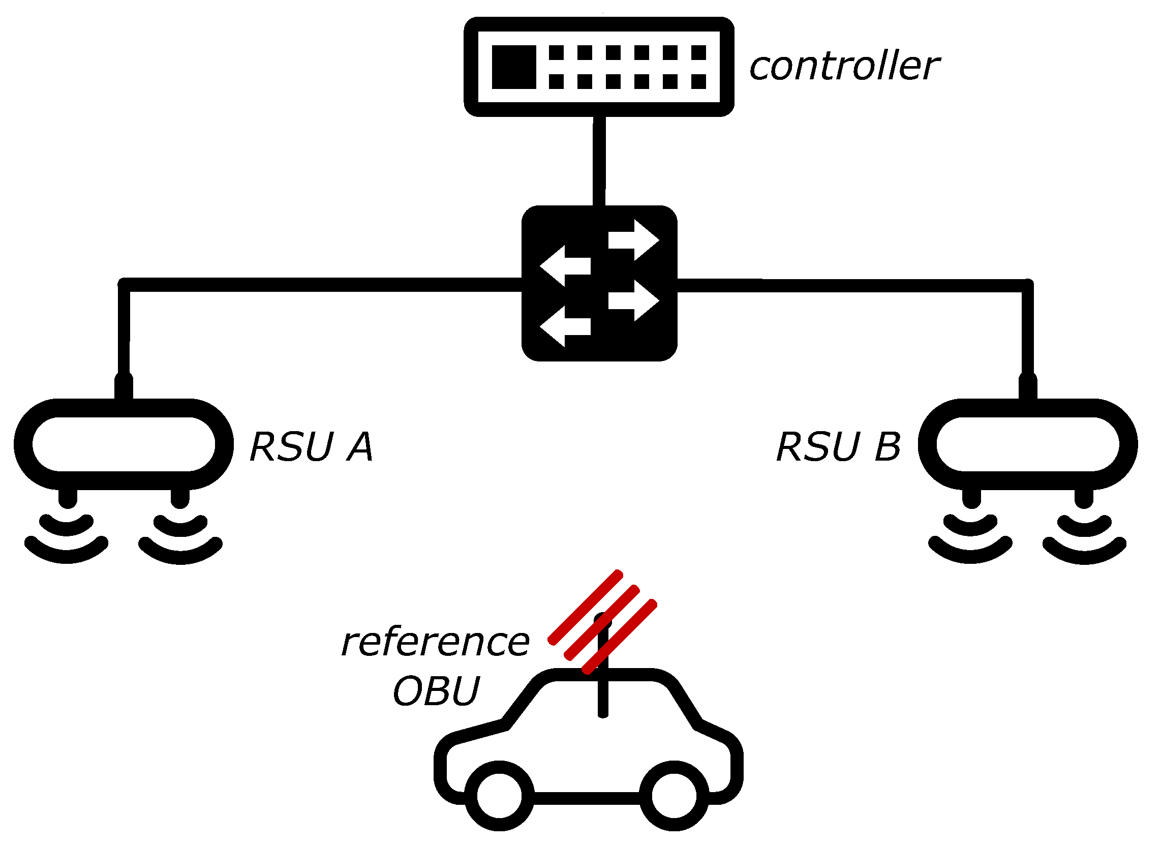
We use the V2X road notation to refer to network nodes mounted on infrastructures as RoadSide Units (RSUs) and to network nodes embedded in vehicles as OnBoard Units (OBUs). The scenario that has been modeled is composed of two RSUs that are out of range of each other, representing RSUs on the side of a highway, and an OBU in the middle called reference OBU that is in the range of both RSUs, representing a vehicle on the road. This models, for instance, a highway scenario where a vehicle might be stationary in the middle of two RSUs due to a queue. In the absence of a coordinator node, the two RSUs would be unable to coordinate with each other, and would, therefore, represent hidden nodes. In the OBU spot, on the other hand, interference may stem from the two RSUs trying to deliver messages like DENMs, and also from other effects such as V2V signaling storms.
To verify the hypothesis and replicate interference on the OBU we designed a test configuration with the goal of being able to send two packets on an IEEE 802.11p channel at the exact same time, in order to maximize the probability for those packets to reach the destination contemporaneously. UDP has been employed as the transport-level protocol, while packet size and transmission rate have been set at 1000 B and 0.1 s (10 Hz), respectively. This is simpler yet functionally equivalent than to use “real” CAM packets. Furthermore, open-source implementations of the ETSI ITS-G5 stack have been investigated, but, in our opinion, they present several criticalities, i.e., on devices such as the Arduino Yún detailed below, they either do not work, or they require complex, error-prone, and time-consuming activities like deep code editing and cross-compilation; moreover, they also appear to use UDP under-the-hood, which supposedly brings the performance with these libraries in line with those obtainable by using UDP directly, as above. The three actively-developed open-source libraries that have been found are the Java ETSI ITS G5 GeoNetworking Stack [32], OpenC2X [33], and Vanetza [34].
4.1. Test Devices
Table 1 lists the devices that we employed for our tests and summarizes their main characteristics. The choice of devices was constrained by having network cards compatible with the Qualcomm Atheros driver “ath9k”, because the open-source implementation of IEEE 802.11p included in the Linux kernel mainline runs in tandem with the Qualcomm Atheros ath9k drivers.
Arduino Yún devices (Yun from now on) have a maximum working frequency of 2.4 GHz, quite different from the 5.9 GHz recommended by the IEEE 802.11p, and an antenna transmission power equal to 18 dBm, that is in most cases the law limit for indoor applications. They have been employed because our preliminary tests indicated that they reliably provide coverage only in a short range (up to 32 m [35]), and that their antenna is directional with a very narrow beam. Therefore, we speculated that, with respect to more powerful solutions, they would be easier to set up in terms of the positioning. Indeed, we found that to be the case, although synchronizing them has been more tricky than expected due to the clock-drift problem mentioned in Section 1. See [16] for more details on Yuns software configuration.
The MikroTik RB912UAG-5HPnD RouterBOARDs (MTik from now on) should support frequencies of up to 5.875 GHz, although the maximum reachable frequency appears to be 5.825 GHz. As the latter frequency, that we used, is almost equal to the lower-bound of 5.850/5.855 GHz defined for V2X DSRC operations, the small difference is not expected to introduce any significant bias in the tests. The most notable feature of these devices is the relatively high transmission power of the integrated wireless card, which can go up to 30 dBm. With respect to the Yuns that embed them, on MTiks we employed two external antennas, with an antenna gain of 3 dBi.
This significant difference in the transmission power between these two kinds of devices is due to regulatory constraints. The ETSI EN 300 328 standard, in fact, imposes a maximum radiated power of 100 mW (20 dBm) over 2.4 GHz and 200 mW (23 dBm) to 1 W (30 dBm) over 5 GHz for indoor and outdoor applications, respectively. As the employed antennas generally have a transmission gain of 2–3 dBi, the transmission power has to be equal to a maximum of 18–17 dBm, respectively, on 2.4 GHz, and 28–27 dBm if over 5 GHz. As Yuns only support 2.4 GHz, their maximum transmission power is 18 dBm, which would give a supposed antenna gain of 2 dBi. As MTiks support 5 GHz, instead, they can use a significantly higher power in order to support outdoor applications over that frequency; in fact, they operate by default at 27 dBm, which equals to a supposed antenna gain of 3 dBi. It is possible to push the transmission power of the Mtik network cards up to 30 dBm before antenna gain, but we will not detail the procedure here.
4.2. Millisecond-Level Synchronization
Figure 1 pictures the testbed. We designed and tested two different methods to implement a millisecond-level synchronization. As shown in Figure 1, a “controller” computer has been connected to the RSUs via same-length CAT 6 Ethernet cables (represented by the full lines connecting the switch to the RSUs in Figure 1). RSUs have been positioned in Line-Of-Sight (LOS) with OBUs in order to avoid shadowing effects as much as possible; static obstacles were admitted only between RSUs, and only if necessary to properly hide RSUs from each other. Only indispensable background processes have been kept active on each operating system.
Both synchronization methods are based on a reference clock, which is the clock of the controller computer. One uses that clock to periodically align the RSUs clock (clock-sharing), which are then used independently to try to send a packet at the same time. The other method uses the reference clock to trigger a “send now order” to the RSUs, which in turn send their packet as soon as they receive the “order”. In the tests presented in this paper, only the latter mechanism is employed, as we consider it more reliable and, at the same time, more similar to what would happen in a real network. We believe so for two reasons. When an emergency message has to be delivered, it would be broadcasted as soon as it is received by an RSU. Moreover, the artificial interference effect is clearly noticeable but less marked with respect to that visible with a (proper) clock-sharing, which means that the interference itself is more similar to reality, where the situation would not be black-and-white but some packets would be correctly received and some other would not. This also allows us to consider the benefits of the time-shifting transmission mechanism under non-optimal circumstances.
The whole procedure consists of two phases: the positioning of devices and the introduction of interference. Each phase is followed by a distinct test, detailed below. If the relative test fails, the phase has to be repeated until the test provides satisfying results.
The positioning starts by finding a proper location for each RSU; the locations are proper when the RSUs cannot ping each other while being in LOS and in range to a third location that can supposedly accommodate the reference OBU. Once the latter is deployed and running, it is used to perform a Received Signal Strength Indicator (RSSI) test, to compare the signal strength received from the two RSUs by executing ‘iw dev intf station dump’. Next, the first RSU shall transmit something to the OBU, stop, and then the second RSU shall do the same and stop. The transmission cycle shall be repeated a few times. What is transmitted is not important, as long as IEEE 802.11p is employed underneath. Ideally, the difference in RSSI values recorded by the reference OBU should be 0. After several tests, we identified the acceptable difference to be within ±1 dBm. If this condition is satisfied, it is possible to proceed (but the less the RSSI difference is, the better). Otherwise, the positioning of devices has to be adjusted, and the RSSI test repeated.
When, on the basis of the three conditions above (no ping between the RSUs, LOS between each RSU and the reference OBU, and a received signal strength within from the RSUs) the position of devices is deemed appropriate, the following test must be run to ensure that interference due to packet collision can be reliably introduced.
- RSU A has to broadcast 100 CAM packets in 10 s, a packet each 100 ms, while RSU B remains silent. Without any additional congestion, we expect the reference OBU to receive ~100% of the packets. We allowed a maximum error of 5%, which means the test fails if less than 95 packets are received.
- RSU B has to broadcast 100 CAM packets in 10 s, a packet each 100 ms, while RSU A remains silent. The conditions have to be the same as those considered for phase 1.
- RSU A and RSU B have to simultaneously broadcast 100 CAM packets in 10 s, a packet each 100 ms. For the interference to be confirmed, the reference OBU has to receive not more than 50% of the packets sent, a successful delivery probability of . Concretely, it means that if the OBU receives more than 100 packets out of a total of 200, the test fails.
Failure can be caused by a number of reasons, for instance, inaccurate positioning of devices, wrongly written scripts, inappropriate scheduling of packets, or improper queueing algorithms. In phase 3, the payloads of each couple of concurrent packets can be the same but, in such a case, it must be assured that the headers are different, in order to exclude any potential constructive interference effects.
4.3. Time-Shifted Transmissions
To mitigate same-frequency interference due to packet collisions, we explored the possibility of shifting some transmissions forward in time. Conceptually, the technique is very simple and consists in making each second RSU transmit only after a time offset of has elapsed. With the testbed and the synchronization method detailed in Section 4.2, it is sufficient to program the controller computer so as to send two trigger messages instead of one every 100 ms, where the second trigger is sent 50 ms after the first one. Without a controller, it is even easier to instruct the RSUs to autonomously broadcast DENMs at different times by making every second RSU use a time offset. Of course, this is only applicable under the assumption that no node would be under the coverage of more than two RSUs, which is the most common case.
If more than two RSUs can reach an OBU, and if RSUs can be sequentially ordered, the formula to calculate the time offset for each RSU is:
where r denotes the RSU, m is the maximum number of RSUs potentially covering the same OBU, is the resulting transmission time offset for RSU r, o is the fixed offset amount, and h is the time after which the subsequent packet would be sent or, in other words, the maximum latency admitted to deliver a packet. For instance, with 5 RSUs potentially covering the same OBU, and , the set of all would be .
If more than two RSUs can reach an OBU, but if they cannot be sequentially ordered, Equation (1) becomes:
with
where extracts a value from O with a uniform distribution and O is the set of non-negative integers that contains the admitted shifts. The latter are found using d as an arbitrary “guard distance” to avoid the occurrence of values too close among each other (e.g., 1 ms, 2 ms, 3 ms, etc.); it is important to strike a balance between a proper guard distance and the total number of values, as if the distance is too large, then the resulting values will be too few after the operation is applied (e.g., if d is set to 50, and m is 5, a likely result might be ).
To test this technique with the testbed depicted in Figure 1, the two RSUs broadcast in 10 s 100 packets each, but RSU B uses a time offset set to 50 ms. We would expect the reference OBU to receive 100% of the CAMs sent, i.e., 200 packets. The time offset has been chosen simply by computing , as being , 50 ms represents the maximum time offset between two subsequent packets from RSU A.
5. Field Tests Results
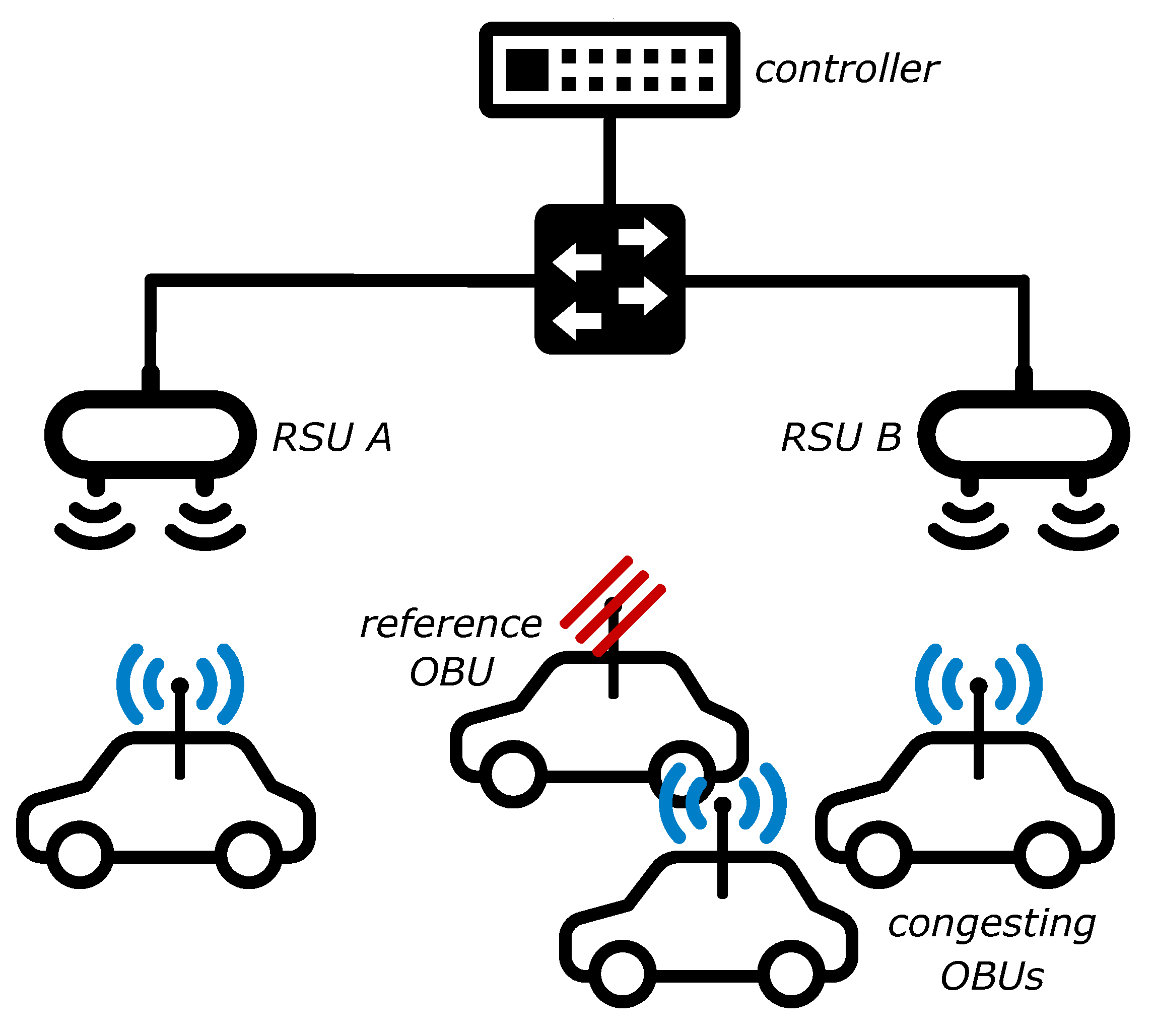
The tests have been firstly run with no additional congestion; then, background traffic has been gradually introduced by running a number of CAM streams on OBUs placed nearby the reference OBU, as depicted in Figure 2. Each CAM stream continuously broadcasts CAM messages with a packet size of 1000 B and a packet transmission frequency of 100 ms. The netcat tool [36] has been used to run multiple instances on each device, in order to model a greater number of vehicles generating V2V traffic with respect to the number of available devices. From our evaluations, the variation in throughput between using x physical devices versus x netcat instances in a lower number of devices amounts to a difference between 1% and 3%.
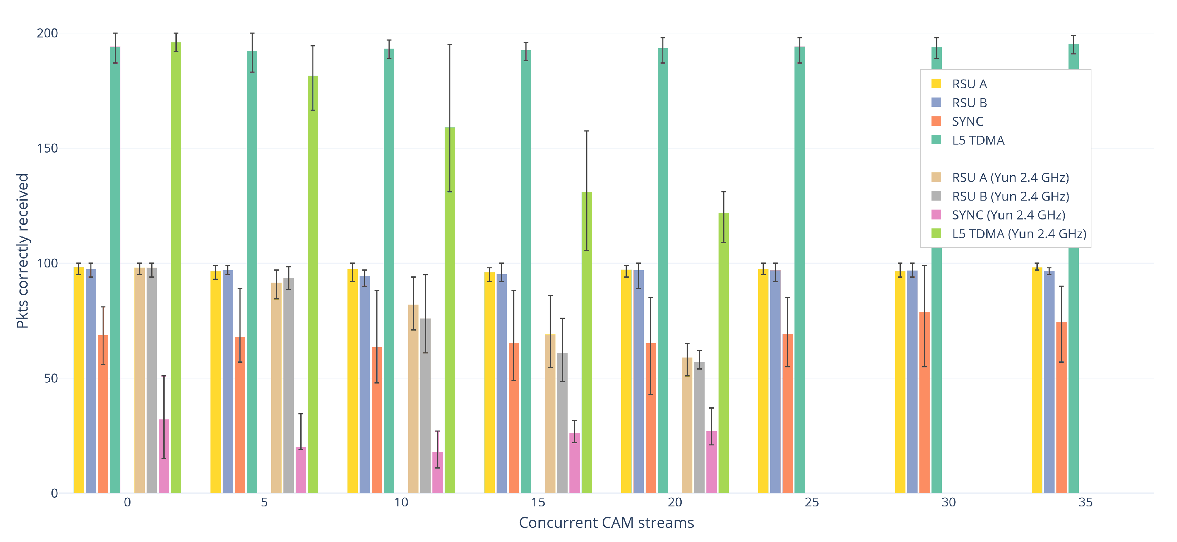
Figure 3 plots the field tests’ results. The horizontal axis is grouped into different amounts of background traffic, with several sets of concurrent CAM streams. Up to 20 included, each stream set shows two bar charts; the leftmost one plots the results for MTiks (missing frequency in the legend), while the rightmost one depicts the results for Yuns (2.4 GHz in the legend). The latter devices were not powerful enough to support 25 streams or more, thus the lack of the rightmost plots in the last sets. The bars height correspond to the average number of packets correctly received by the reference OBU with the relative transmission policy, while the error bars indicate the range of results. Figures were calculated over a total of 5 runs for each combination of policy and number of background streams, i.e., 5 runs for each bar of Figure 3. RSU A shows the transmission performance when only RSU A transmits; the same applies to RSU B. SYNC displays the number of packets received by the reference OBU under the artificial interference that has been introduced with the synchronization mechanism detailed in Section 4.2. L5 TDMA shows instead the effects of time-shifting the transmissions as defined in Section 4.3.
5.1. No Congestion
Here are analyzed the results obtained without any congesting background stream. There is nothing remarkable about the values for RSU A and RSU B, they are in line with the expectations in all cases. In the SYNC bars, the packet collision interference is clearly visible on both devices (the SYNC value has to be compared not with RSU A or RSU B, but with the total number of packets sent, that is 200), which confirms that the millisecond-level synchronization outlined in Section 4.2 can provide reliable guarantees about concurrent packet transmissions on the reference clock’s basis. Yet, there is a significant difference between the effects on MTiks versus those on Yuns. The number of packets received by MTiks is roughly double than the number regarding Yuns. Yuns were positioned at much shorter distances (~20 m versus ~60 m for MTiks), while their RSSI test (see Section 4.2) yielded better values (less difference); indeed, MTiks have in general been much harder to position correctly. However, we suspect that, due to various factors such as the external antennas, the higher power network cards, MTiks have better sensitivity and would have been able to correctly decode more packets than Yuns even with the same RSSI difference. Anyhow, the benefits of L5 TDMA are unambiguous with both kinds of devices.
5.2. With Congestion
Except for SYNC that deserves a separate note, the performances are in general stable with MTiks, but degrade very quickly with Yuns, even with only 5 CAM streams in the background. Regarding Yuns, and with the exception, again, for SYNC, it holds that as the congestion increases, the performances decrease. To verify if this property would hold as expected with higher-power devices, a greater number of these devices than those at our disposal would be necessary. Yuns here are very useful as they amplify the effects that with MTiks would supposedly be visible with much higher degrees of congestion. However, it must be noted that 35 is already a good number of background streams, useful to assess worst-case performances at short/medium distances. Running more than 35 total CAM instances with our number of devices has been found to be inconsequential, as their capabilities get quickly saturated after that point.
SYNC seems to exhibit a peculiar tendency with both kinds of devices, that is, values follow a concave pattern with the increase of congestion. The shape is more visible with Yuns, but is exhibited by MTiks too, although more subtly.
6. Conclusions
In the context of IEEE 802.11p networks, this paper presented a repeatable millisecond-level synchronization mechanism to artificially introduce at a host premises destructive interference due to hidden terminals packet collisions. The paper also outlined a time-shifting application-level technique to minimize the interference and generalized it to also account for corner cases. Both procedures are applicable to devices of any transmission power, demonstrated by the inclusion of very different devices in the field tests. Indeed, the paper also includes the results given by field-testing both procedures. These attest that interference due to hidden terminals may occur, although the significance of the issue is debated, and that carefully employing simple time offsets for transmissions can substantially mitigate interference, even in very congested scenarios.
Author Contributions
Conceptualization, M.K., C.A.G. and M.C.; Methodology, C.A.G.; Validation, M.K. and C.A.G.; Formal analysis, M.K.; Investigation, M.K. and C.A.G.; Data curation, M.K.; Writing—original draft, M.K.; Writing—review and editing, M.K. and M.C.; Supervision, M.C.; Project administration, M.C.; Funding acquisition, M.C. All authors have read and agreed to the published version of the manuscript.
Funding
Alstom Group has partially funded this work. All statements, facts, and figures represent the sole view of the authors.
Conflicts of Interest
The authors declare no conflict of interest. The funders had no role in the design of the study; in the collection, analyses, or interpretation of data; in the writing of the manuscript, or in the decision to publish the results.
References
- Kenney, J.B. Dedicated Short-Range Communications (DSRC) Standards in the United States. Proc. IEEE 2011, 99, 1162–1182. [Google Scholar] [CrossRef]
- Request for Comments: V2X Communications; DOT-OST-2018-0210-0001; US Department of Transportation: Washington, DC, USA, 2018.
- Soliman, M.; Unterhuber, P.; Gera, D. First analysis of inside train communication with ITS-G5 measurement data. In Proceedings of the 2016 International Symposium on Wireless Communication Systems (ISWCS), Poznań, Poland, 20–23 September 2016; pp. 451–455. [Google Scholar]
- Karlsson, K.; Bergenhem, C.; Hedin, E. Field measurements of IEEE 802.11 p communication in NLOS environments for a platooning application. In Proceedings of the 2012 IEEE Vehicular Technology Conference (VTC Fall), Yokohama, Japan, 6–9 May 2012; pp. 1–5. [Google Scholar]
- Hyvönen, M.; Rajala, M.; Virtanen, A.; Jankkari, J.; Huhtala, K.; Ritala, R. Assistive situation awareness system for mobile multimachine work environments. IEEE Trans. Intell. Transp. Syst. 2015, 16, 3403–3413. [Google Scholar] [CrossRef]
- Klingler, F.; Blobel, J.; Dressler, F. Agriculture meets IEEE 802.11 p: A feasibility study. In Proceedings of the 2018 15th International Symposium on Wireless Communication Systems (ISWCS), Lisbon, Portugal, 28–31 August 2018; pp. 1–6. [Google Scholar]
- Bellalta, B.; Belyaev, E.; Jonsson, M.; Vinel, A. Performance Evaluation of IEEE 802.11p-Enabled Vehicular Video Surveillance System. IEEE Commun. Lett. 2014, 18, 708–711. [Google Scholar] [CrossRef]
- Jain, V.; Lapoehn, S.; Frankiewicz, T.; Hesse, T.; Gharba, M.; Gangakhedkar, S.; Ganesan, K.; Cao, H.; Eichinger, J.; Ali, A.R.; et al. Prediction based framework for vehicle platooning using vehicular communications. In Proceedings of the 2017 IEEE Vehicular Networking Conference (VNC), Torino, Italy, 27–29 November 2017; pp. 159–166. [Google Scholar] [CrossRef]
- Stahlmann, R.; Möller, M.; Brauer, A.; German, R.; Eckhoff, D. Exploring GLOSA systems in the field: Technical evaluation and results. Comput. Commun. 2018, 120, 112–124. [Google Scholar] [CrossRef]
- Stahlmann, R.; Tornatis, A.; German, R.; Eckhoff, D. Multi-hop for GLOSA systems: Evaluation and results from a field experiment. In Proceedings of the 2017 IEEE Vehicular Networking Conference, Torino, Italy, 27–29 November 2017; pp. 175–178. [Google Scholar] [CrossRef]
- Urbano, M.; Alam, M.; Ferreira, J.; Fonseca, J.; Simíões, P. Cooperative driver stress sensing integration with eCall system for improved road safety. In Proceedings of the IEEE EUROCON 2017 -17th International Conference on Smart Technologies, Ohrid, Macedonia, 6–8 July 2017; pp. 883–888. [Google Scholar] [CrossRef]
- Bastani, S.; Landfeldt, B. The Effect of Hidden Terminal Interference on Safety-Critical Traffic in Vehicular Ad Hoc Networks. In Proceedings of the 6th ACM Symposium on Development and Analysis of Intelligent Vehicular Networks and Applications, Valletta, Malta, 13–17 November 2016; ACM: New York, NY, USA, 2016; pp. 75–82. [Google Scholar] [CrossRef]
- Sjoberg, K.; Uhlemann, E.; Strom, E.G. How Severe Is the Hidden Terminal Problem in VANETs When Using CSMA and STDMA? In Proceedings of the 2011 IEEE Vehicular Technology Conference (VTC Fall), Budapest, Hungary, 15–18 May 2011; pp. 1–5. [Google Scholar] [CrossRef] [Green Version]
- Tomar, R.S.; Sharma, M.S.P.; Jha, S.; Chaurasia, B.K. Performance Analysis of Hidden Terminal Problem in VANET for Safe Transportation System. In Harmony Search and Nature Inspired Optimization Algorithms; Yadav, N., Yadav, A., Bansal, J.C., Deep, K., Kim, J.H., Eds.; Springer: Singapore, 2019; pp. 1199–1208. [Google Scholar]
- Torrent-Moreno, M.; Corroy, S.; Schmidt-Eisenlohr, F.; Hartenstein, H. IEEE 802.11-based One-hop Broadcast Communications: Understanding Transmission Success and Failure Under Different Radio Propagation Environments. In Proceedings of the 9th ACM International Symposium on Modeling Analysis and Simulation of Wireless and Mobile Systems, Malaga, Spain, 2–6 October 2006; ACM: New York, NY, USA, 2006; pp. 68–77. [Google Scholar] [CrossRef]
- Klapez, M.; Grazia, C.A.; Casoni, M. IEEE 802.11p field trials on interference minimization for safety-related V2X applications. In Proceedings of the 2019 15th International Conference on Wireless and Mobile Computing, Networking and Communications (WiMob), Barcelona, Spain, 21–23 October 2019; pp. 262–269. [Google Scholar] [CrossRef]
- Intelligent Transportation Services; FCC. Report and Order; FCC-99-305. 1999. Available online: https://www.fcc.gov/document/intelligent-transportation-services (accessed on 26 March 2020).
- Intelligent Transport Systems (ITS). ITS-G5 Access Layer Specification for Intelligent Transport Systems Operating in the 5 GHz Frequency Band; ETSI, Draft ETSI EN 302 663 V1.3.1. 2020. Available online: https://www.etsi.org/standards#Pre-defined%20Collections (accessed on 26 March 2020).
- IEEE 802.11p-2010—IEEE Standard for Information Technology—Local and Metropolitan Area Networks—Specific Requirements—Part 11: Wireless LAN Medium Access Control (MAC) and Physical Layer (PHY) Specifications Amendment 6: Wireless Access in Vehicular Environments. 2010. Available online: https://standards.ieee.org/standard/802_11p-2010.html (accessed on 26 March 2020).
- ASTM E2213-02. Standard Specification for Telecommunications and Information Exchange Between Roadside and Vehicle Systems—5 GHz Band Dedicated Short Range Communications (DSRC) Medium Access Control (MAC) and Physical Layer (PHY) Specifications; ASTM International: West Conshohocken, PA, USA, 2002. [Google Scholar]
- ASTM E2213-03. Standard Specification for Telecommunications and Information Exchange Between Roadside and Vehicle Systems—5-GHz Band Dedicated Short-Range Communications (DSRC), Medium Access Control (MAC), and Physical Layer (PHY) Specifications; ASTM International: West Conshohocken, PA, USA, 2018. [Google Scholar]
- IEEE Standard for Information Technology—Telecommunications and Information Exchange between Systems-Local and Metropolitan Area Networks—Specific Requirements-Part 11: Wireless LAN Medium Access Control (MAC) and Physical Layer (PHY) Specifications. IEEE Std 802.11-2016 (Revision of IEEE Std 802.11-2012). 2016. Available online: https://ieeexplore.ieee.org/document/7786995 (accessed on 26 March 2020).
- IEEE 1609.2, IEEE Trial-Use Standard for Wireless Access in Vehicular Environments (WAVE) Security Services for Applications and Management Messages. 2006. Available online: https://ieeexplore.ieee.org/document/1653011/versions#versions (accessed on 26 March 2020).
- IEEE 1609.3, IEEE Trial-Use Standard for Wireless Access in Vehicular Environments (WAVE)-Networking Services. 2007. Available online: https://ieeexplore.ieee.org/document/4167674 (accessed on 26 March 2020).
- IEEE 1609.4, Trial-Use Standard for Wireless Access in Vehicular Environments (WAVE) Multi-Channel Operation. 2006. Available online: https://ieeexplore.ieee.org/document/4025692 (accessed on 26 March 2020).
- Dedicated Short Range Communications (DSRC) Message Set Dictionary, SAE, J2735_201603. 2016. Available online: https://www.sae.org/standards/content/j2735_201603/ (accessed on 26 March 2020).
- Dedicated Short Range Communication (DSRC) Systems Engineering Process Guidance for SAE J2945/X Documents and Common Design Concepts, SAE, J2945_201712. 2017. Available online: https://www.sae.org/standards/content/j2945_201712/ (accessed on 26 March 2020).
- Bai, F.; Stancil, D.D.; Krishnan, H. Toward Understanding Characteristics of Dedicated Short Range Communications (DSRC) from a Perspective of Vehicular Network Engineers. In Proceedings of the Sixteenth Annual International Conference on Mobile Computing and Networking, Chicago, IL, USA, 20–24 September 2010; ACM: New York, NY, USA, 2010; pp. 329–340. [Google Scholar] [CrossRef]
- Intelligent Transport Systems (ITS); Vehicular Communications; Basic Set of Applications; Part 2: Specification of Cooperative Awareness Basic Service, ETSI EN 302 637-2 V1.4.1; 2019-04. Available online: https://www.etsi.org/deliver/etsi_en/302600_302699/30263702/01.04.01_60/en_30263702v010401p.pdf (accessed on 26 March 2020).
- Intelligent Transport Systems (ITS); Vehicular Communications; Basic Set of Applications; Part 3: Specifications of Decentralized Environmental Notification Basic Service, ETSI EN 302 637-3 V1.3.1. Available online: https://www.etsi.org/deliver/etsi_en/302600_302699/30263703/01.03.01_60/en_30263703v010301p.pdf (accessed on 26 March 2020).
- Karn, P. MACA-a new channel access method for packet radio. In Proceedings of the ARRL/CRRL Amateur Radio 9th Computer Networking Conference, London, ON, Canada, 22 September 1990; Volume 140, pp. 134–140. [Google Scholar]
- Voronov, A.; De Jongh, J.; Heuven, D.; Severinson, A. Implementation of ETSI ITS G5 GeoNetworking Stack; Java: CAM-DENM/ASN. 1 PER/BTP/GeoNetworking. Available online: https://github.com/alexvoronov/geonetworking (accessed on 26 March 2020).
- Laux, S.; Pannu, G.S.; Schneider, S.; Tiemann, J.; Klingler, F.; Sommer, C.; Dressler, F. OpenC2X—An open source experimental and prototyping platform supporting ETSI ITS-G5. In Proceedings of the 2016 IEEE Vehicular Networking Conference (VNC), Columbus, OH, USA, 8–10 December 2016; pp. 1–2. [Google Scholar]
- Vanetza: An Open-Source Implementation of the ETSI C-ITS Protocol Stack, Car2X-Laboratory at Technische Hochschule Ingolstadt. 2019. Available online: https://github.com/alexvoronov/geonetworking (accessed on 26 March 2020).
- Klapez, M.; Grazia, C.A.; Rold, L.; Casoni, M. IEEE 802.11p under congestion in an Infrastructure-to-Vehicle communication approach. In Proceedings of the 2019 AEIT International Conference of Electrical and Electronic Technologies for Automotive (AEIT AUTOMOTIVE), Turin, Italy, 2–4 July 2019; pp. 1–6. [Google Scholar] [CrossRef]
- The GNU Netcat Project, Free Software Foundation. 2004. Available online: http://netcat.sourceforge.net (accessed on 26 March 2020).
Figure 1.
Testbed: elements.

Figure 2.
Testbed with congestion: elements.

Figure 3.
Packets correctly received by the reference OBU as a function of transmission policy and background congestion.
Figure 3.
Packets correctly received by the reference OBU as a function of transmission policy and background congestion.


Table 1.
Devices specifications.
| Device | Architecture | Network Card | Working Frequency | Max Tx Power |
|---|---|---|---|---|
| Arduino Yún | MIPS | AR9331 SoC | 2.4 GHz | 18 dBm |
| MikroTik RB912UAG-5HPnD | MIPS | AR9342 SoC | 5.8 GHz | 30 dBm |
© 2020 by the authors. Licensee MDPI, Basel, Switzerland. This article is an open access article distributed under the terms and conditions of the Creative Commons Attribution (CC BY) license (http://creativecommons.org/licenses/by/4.0/).
Share and Cite
MDPI and ACS Style
Klapez, M.; Grazia, C.A.; Casoni, M. Minimization of IEEE 802.11p Packet Collision Interference through Transmission Time Shifting. J. Sens. Actuator Netw. 2020, 9, 17. https://doi.org/10.3390/jsan9020017
AMA Style
Klapez M, Grazia CA, Casoni M. Minimization of IEEE 802.11p Packet Collision Interference through Transmission Time Shifting. Journal of Sensor and Actuator Networks. 2020; 9(2):17. https://doi.org/10.3390/jsan9020017
Chicago/Turabian StyleKlapez, Martin, Carlo Augusto Grazia, and Maurizio Casoni. 2020. "Minimization of IEEE 802.11p Packet Collision Interference through Transmission Time Shifting" Journal of Sensor and Actuator Networks 9, no. 2: 17. https://doi.org/10.3390/jsan9020017
Note that from the first issue of 2016, this journal uses article numbers instead of page numbers. See further details here.