Hydrodynamic Efficiency of a Wave Energy Converter in Front of an Orthogonal Breakwater


Laboratory for Floating Structures and Mooring Systems, Division of Marine Structures, School of Naval Architecture and Marine Engineering, National Technical University of Athens, 9 Heroon Polytechniou Avenue, 157-73 Athens, Greece
*
Author to whom correspondence should be addressed.
J. Mar. Sci. Eng. 2021, 9(1), 94; https://doi.org/10.3390/jmse9010094
Submission received: 24 December 2020
/
Revised: 11 January 2021
/
Accepted: 15 January 2021
/
Published: 17 January 2021
(This article belongs to the Special Issue Breakwater Behaviour)
Abstract
:In the present study, the hydrodynamic efficiency of a cylindrical wave energy converter (WEC) of vertical symmetry axis and arranged in front of a reflecting orthogonal breakwater is explored. The idea is based on exploiting the anticipated amplification of the scattered and the reflected wave fields originating from the presence of the vertical walls, towards increasing the WEC’s wave power absorption due to the walls’ wave reflections. Two types of converters are examined, namely the heaving device and the oscillating water column (OWC) device, assuming linear potential theory. The associated diffraction-, motion-, and pressure-radiation problems are solved using axisymmetric eigenfunction expansions for the velocity potential around the WECs by properly accounting for the wave field’s modification due to the walls’ presence. To this end, a theoretical formulation dealing with the evaluation of the converter’s performance is presented accounting for the coupling between the WEC and the reflecting vertical walls. The results depict that the amount of the harvested wave power by the WEC in front of an orthogonal wall is amplified compared to the absorbed wave power by the same WEC in the open sea.
1. Introduction
Europe leads the way in the development of ocean energy technologies, hosting most global developers (66% of tidal energy patents and 44% of wave energy) [1] with over 25 MW of ocean energy installed capacity at the end of 2017, up from 12 MW declared in 2016. The ocean energy industry estimates that 100 GW of capacity can be deployed in Europe by 2050 [2]. However, according to the IRENA report [3], the levelized cost of electricity (LCOE) for wave energy is 440 €/MWh, whilst tidal sits at approximately 380 €/MWh, highlighting the major disparity between the cost of ocean wave and tidal energy, which remains high, when compared to other energy technologies from different natural resources.
Despite the high energy potential available offshore, significant challenges inhibit ocean wave energy converter (WEC) deployment such as (a) the high cost of installation; maintenance, and connection to the electricity grid; (b) the challenging ocean climate conditions; (c) the potential negative environmental issues related to the installation and operation phases of such facilities; (d) the occurred disturbances for private and commercial vessels routes; and (e) the lack of insurability surrounding ocean energy harvesting systems [4]. Therefore, WEC installation and operation near- and on-shore has been happening in the last decades in almost all the nearshore European regions as an ideal choice for wave energy absorption aiming at reducing the LCOE level. Furthermore, the installation of WECs in front and on existing maritime facilities, such as a breakwater or a harbor is triggered by easier electricity transmission to the mainland allowing for common infrastructure (i.e., electrical cable, power transfer equipment, etc.) and the reduction of the wave action intensity on the shore protecting and maintain the boundaries of coastal regions [5].
Breakwaters are shore-parallel structures built offshore to reduce wave energy reaching the shoreline through the dissipation, reflection, or diffraction of oncoming waves. Several types of breakwaters have already been implemented based on their form of operation, namely: (a) reflecting—fully protecting bottom fixed or floating; (b) permeable breakwaters comprising of piles or perforated and slotted structure; (c) semicircular; and (d) submerged breakwaters, while under these broad classifications they can be further sub-divided concerning their shape, construction materials, etc. [6].
In the framework of WEC-breakwater systems, numerous design concepts and descriptions have been presented in the literature, exhibiting the ability of a breakwater in enhancing the efficiency of a converter. Most of them concern the overtopping devices, the heaving WECs, and the oscillating water column (OWC) devices. Regarding the last two categories (i.e., heaving and OWC WECs), which form the core of the present contribution, the WEC-breakwater systems received special attention, with the WECs being installed either in front of a linear wall (i.e., vane-type breakwater) or integrated at it. A number of studies have been presented in the literature dealing with WECs integrated into floating or bottom mounted breakwaters. Most recent indicative examples are those of [7,8,9,10] studying integrated WECs into bottom mounted breakwaters, whereas floating integrated WEC-breakwater systems were recently studied in [11,12,13,14]. In addition, floating WEC-breakwaters consisting of rectangular caissons and multiple pontoons have been investigated in [15,16,17]. Regarding WECs located in front of a linear vertical wall and particularly OWC devices considered either alone in the wave field or as part of an array, recent studies [18,19] have shown the amplification of the devices’ efficiency due to the presence of a vane-type breakwater. Additionally, a linear breakwater with parabolic openings, as a parabolic reflector, has been studied to converge propagating waves toward a focus point, in which the wave height is further amplified compared to the wave height in front of a vane-type vertical wall [20]. Furthermore, the efficiency of an array of heaving WECs located in front of a linear breakwater has been studied recently in [21,22,23]. In these investigations, the method of images [24,25] was utilized to simulate the presence of the vertical wall, thus a fully reflecting, bottom seated, surface piercing breakwater of infinite length was considered.
Pointing towards the abilities provided by linear breakwater systems, alternative types of breakwater-configurations have been also examined worldwide, namely V-shaped, and orthogonal breakwaters. Several different types of patents offering different types of V-shaped breakwaters have been presented in the last decades [26,27], whereas in May 1999 the U.S. Army Engineer Research and Development Center designed a novel concept of floating breakwaters composed of two arms in a “V-shape” to promote the stability of vessel loading/offloading activities [28,29]. Pioneering works on the wave effects on V-shaped breakwaters are [30,31,32,33]. Concerning the investigations on the behavior of WECs placed in front of V-shaped breakwaters, theoretical and experimental studies were developed in [34,35], whereas the effect of a sea-bottom fixed orthogonal breakwater on the hydrodynamics of bottom seated or floating cylindrical bodies has been studied in [36,37,38].
The aim of this work was to study the effect of an orthogonal vertical wall on the absorbed wave power by a single WEC placed in a random location in front of the two walls. Two WEC types of different operating principles were examined, namely (a) the single-body heaving wave energy converter, using a floater (buoy) allowed to move only in heave direction, exploiting the oscillating force of the waves to generate electricity; and (b) the oscillating water column wave energy converter, OWC, using the oscillation of water within a chamber, in which the air inside the chamber is compressed or decompressed actuating an air-driven turbine and generate electricity. Towards this goal the hydrodynamic characteristics (exciting wave forces, motion- and pressure-hydrodynamic coefficients) of the examined WECs were evaluated taking into consideration the hydrodynamic interactions between the converter and the adjacent breakwaters. The absorbed wave power by each WEC is presented and compared in form of figures for several examined parameters: (a) distances between the converter and the wall; (b) wave heading angles; (c) converter’s geometric characteristics; and (d) breakwaters’ length. The presented results show that the wave power absorption of a converter in front of an orthogonal breakwater is amplified compared to the hydrodynamic efficiency (i.e., absorbed wave power) of the same device in unbounded waters (i.e., without the existence of the vertical walls) and its values are dependent on the wave number (i.e., wave frequency); floaters’ geometry; floaters’ distance from the walls; wave incidence; and walls’ length.
The present manuscript is structured as follows. Section 2 describes the applied methodology of images simulating the orthogonal breakwater, as well as the solution of the corresponding diffraction and motion- and pressure-radiation problems. In Section 3, the efficiency of each examined converter is presented as a function of the body’s hydrodynamic characteristics (exciting forces and moments, motion- and pressure-hydrodynamic coefficients, and Power-Take-Off (PTO) characteristics), whereas Section 4 is devoted to the presentation of numerical results and the floaters’ wave power absorption assessment. Finally, in Section 5 the conclusions are drawn.
2. Methodology of the Hydrodynamic Problem
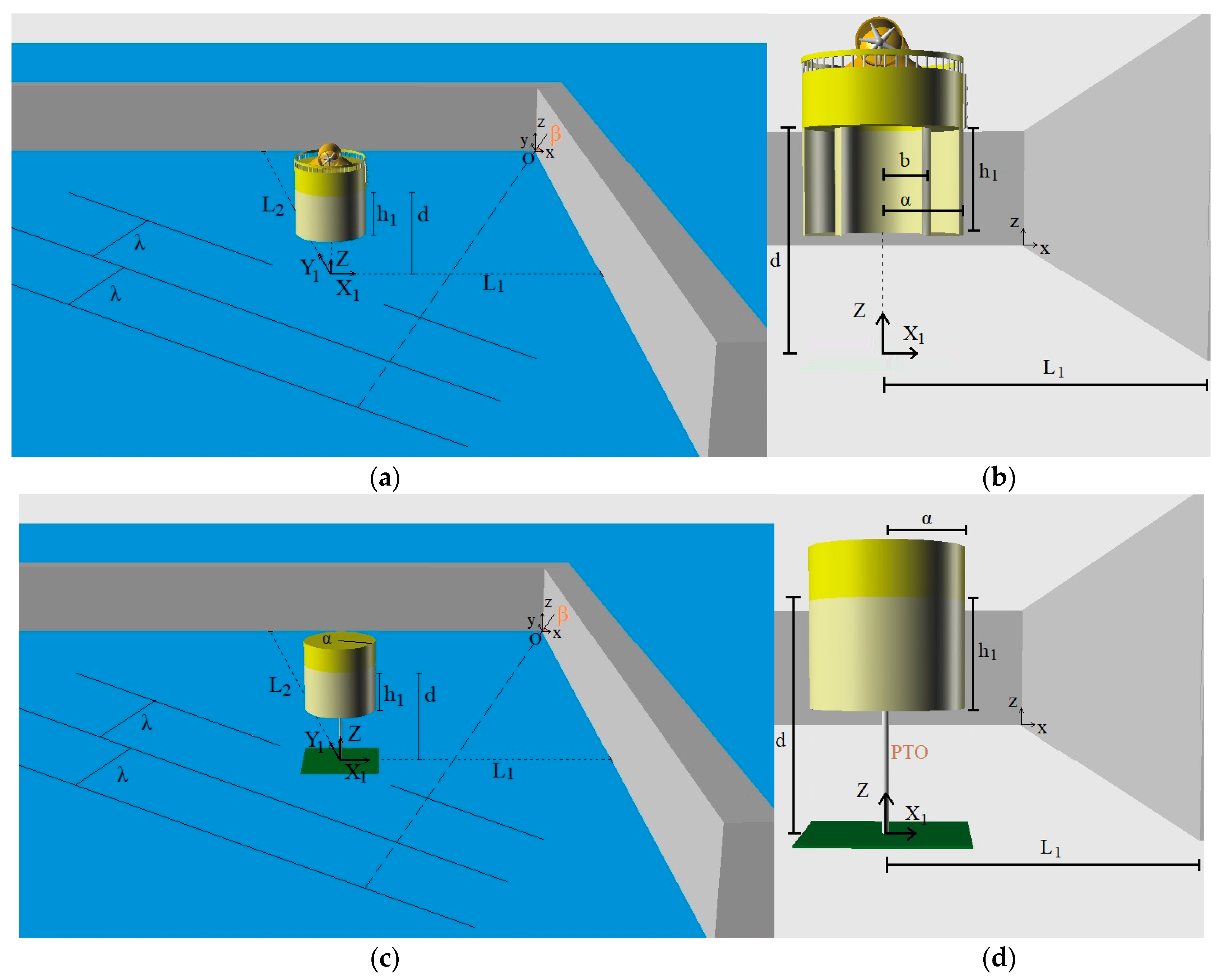
A vertical, bottom-standing, surface piercing, orthogonal breakwater of infinite length was situated in water of constant depth d. The wall was formed with two straight arms (walls) forming a right angle (i.e., 90°). The arms were assumed rigid and impermeable. A harmonic wave train (with angular frequency ω and wave height H) was incident to the breakwater at an angle β. A global, right-handed Cartesian co-ordinate system O-xyz was introduced with origin located at the seabed at the connection point of the two arms of the breakwater, with its vertical axis Oz pointing upwards. A local cylindrical co-ordinate system was defined with origins at the intersection of the sea bottom with the vertical axis of symmetry of the converter. The distances between the arms of the breakwater and the center of the converter are denoted by and . Concerning the geometrical characteristics of the examined WECs, the radius and the draught of the heaving device are denoted by α and , respectively, whereas for the OWC the inner and outer radius and the draught are denoted by b, α and , respectively. The geometric layout of the problem is depicted in Figure 1.
Under the assumption of small-amplitude, inviscid, incompressible, and irrotational flow, linear potential theory can be employed and the fluid flow around the converter (i.e., heaving device or OWC) can be written in terms of a velocity potential that is:
The potential is solution of the Laplace equation in the entire fluid domain and satisfies the no-flux boundary condition on the sea bed; the proper boundary conditions on the free surface for the heaving device and for the OWC, as well as the kinematic conditions on the mean WECs’ wetted surface [39]. Furthermore, two proper boundary conditions on the breakwater arms should be fulfilled, namely [24]:
Finally, a radiation condition stating the outgoing propagating disturbances must be imposed.
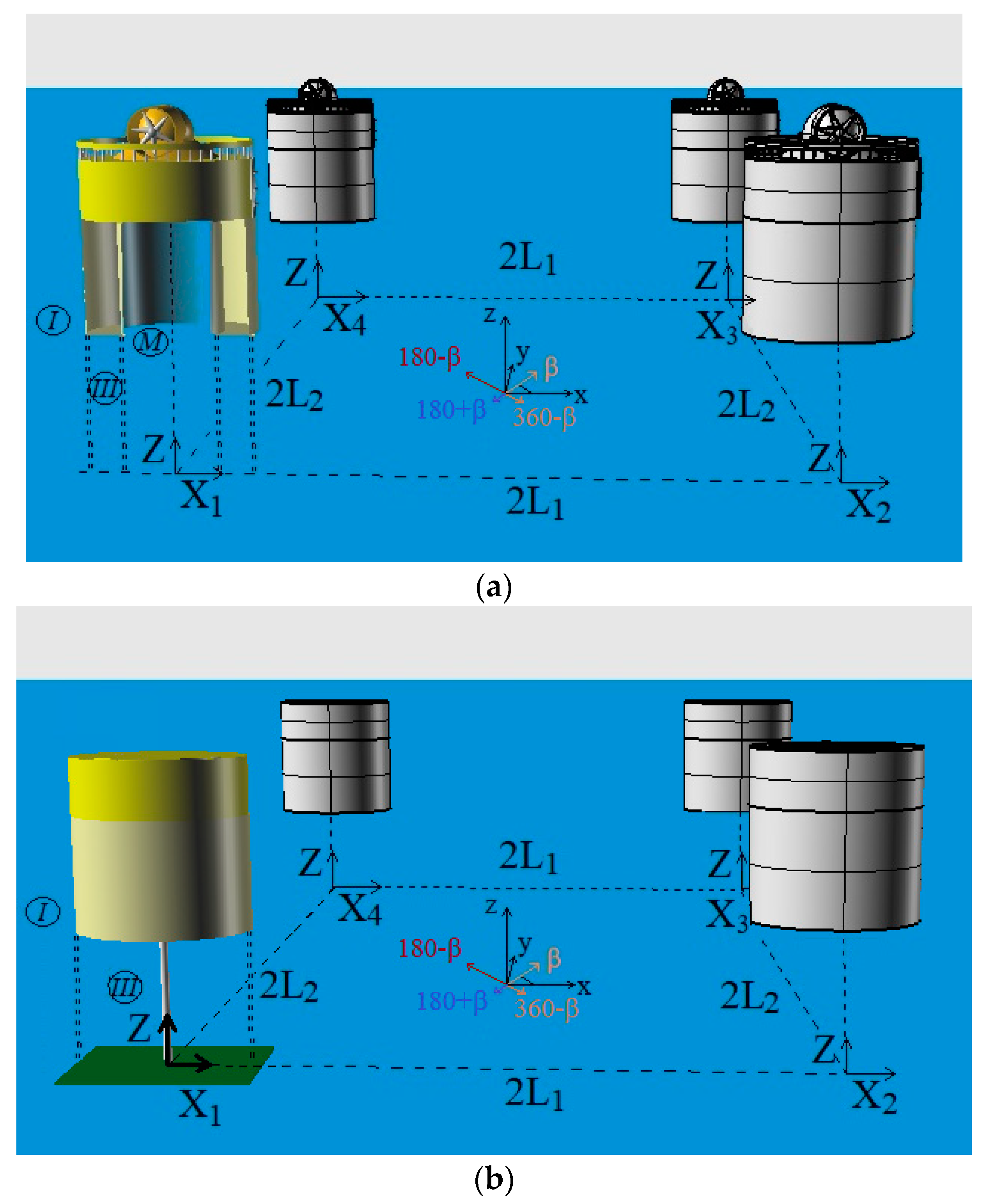
Applying the method of images, the investigated system (i.e., converter-orthogonal breakwater system) corresponds to an array of four similar WECs consisting of the initial converter and its three mirror virtual bodies with respect to the two vertical walls that are exposed to the action of four-directional surface waves (i.e., one propagating at angle β, a second at angle 180 − β, a third at angle 180 + β, and a fourth at angle 360 − β) without, however, the presence of the vertical walls [38]. Herein, four local cylindrical co-ordinate systems are defined with origins at the intersection of the sea bottom with the vertical axis of symmetry of each converter (see Figure 2). Following [40], it holds:
For the heaving device:
For the OWC device:
Here, denotes the velocity potential of the undisturbed incident harmonic wave; stands for the scattered potential around the q converter, when it is considered restrained in the wave impact with the duct open (for the OWC configuration) to the atmosphere, so that the pressure in the chamber equals to the atmospheric one; is the motion-dependent radiation potential around the q heaving device resulting from the forced oscillation of the p device in the heave direction; and is the pressure-dependent radiation potential around the q OWC when it is considered restrained to the wave train and open to the atmosphere due to inner air pressure in the chamber of the p OWC, which is considered fixed in otherwise calm water. In Equation (4), stands for the velocity amplitude in heave direction of p heaving device, whereas in Equation, (5) denotes the amplitude of the oscillating pressure head in the the p OWC chamber. In both Equations (4) and (5), denotes the diffraction components.
The induced velocity potentials are determined using the method of matched axisymmetric eigenfunctions expansions. Specifically, the flow field around each WEC q, q = 1, 2, 3, 4 is subdivided in coaxial ring-shaped fluid regions, denoted by I and III (see Figure 2), whereas for the OWC, there is an additional coaxial ring-shaped fluid region inside the oscillated chamber, denoted by M (see also Figure 2). In these fluid regions different series expansions of the velocity potential can be formed, which are solutions of the Laplace equation and satisfy:
- The boundary condition on the free surface for the heaving device:whereas for the OWC device it holds:
- The boundary condition on sea bottom:
- The kinematic boundary condition on the mean converter’s wetted surface:and the boundary condition at infinity.
Here, g is the acceleration due to gravity; ρ is the water density; is the derivative in the direction of the outward unit normal vector to the mean wetted surface of the q converter, q = 1, 2, 3, 4; is the Kronecker’s symbol; is the generalized normal component, whereas the superscripts I, III, M denote the corresponding fluid domain.
Moreover, following the method of matched axisymmetric eigenfunctions expansions, the velocity potentials and their derivatives must be continuous at the vertical boundaries of adjacent fluid regions [39].
The solution of the relevant linearized diffraction, motion, and pressure radiation problems requires the determination of the hydrodynamic interaction effects between the converters in the array. These effects, namely the wave interaction phenomena among the bodies of the array, are evaluated using the multiple scattering approach [41] and the single-body hydrodynamic characteristics of the individual converters. According to this method the incident wave potential and various orders of propagating wave modes scattered and radiated from the members of the array are superposed to obtain exact series representations of the total wave field around each body of the configuration. Apart from its high accuracy [42], this method requires low computer storage since there is no need to retain simultaneously the unknown partial wave amplitudes around all the floaters as the boundary conditions on each converter of the array are successively fulfilled.
The undisturbed incident harmonic wave velocity potential involved in Equations (4) and (5), that propagates at an angle θ (i.e., θ = β, 180 − β, 180 + β, 360 − β) with respect to the positive x-axis, can be written in the co-ordinate system of the q converter; it holds:
where
In Equation (12), stands for the m-th order Bessel function of the first kind; whereas denote the polar coordinates of the q converter center relative to the origin O of the global co-ordinate system O–xyz. The term denotes an orthonormal function in [0, d] described as follows:
The velocity potentials, , , described in Equations (4) and (5) written in the q-th converter’s cylindrical coordinate system form:
The functions are the principal unknowns of the problem. These are evaluated by employing the multiple scattering approach for the determination of the hydrodynamic interaction phenomena among the converters of the array (i.e., one initial and three mirror bodies), with the required single body hydrodynamic characteristics being established through the use of matched axisymmetric eigenfunctions expansions around each body of the multi-body arrangement. By accounting for the fulfillment of the proper boundary conditions (as being presented in Equations (6)–(10)), along with the conditions for continuity of the flow potential and its radial velocity at the common boundaries of adjacent fluid regions, linear systems of equations can be established for determining the unknown coefficients of the series expansions in each fluid domain. The method has been described in the past [39,43], thus it is no further elaborated here.
3. WEC Power Efficiency
3.1. Hydrodynamic Forces
Applying the method of images on the WEC-breakwater system, the heave exciting forces on the converter when exposed to the action of a regular wave train propagating at an angle β, equal to the sum of the exciting forces acting on the WEC for wave angles β, 180 − β, 180 + β, 360 − β, assuming, however, the presence of three mirror bodies, placed with respect to the vertical walls, without the presence of the breakwater (see Figure 2). Concerning the motion dependent hydrodynamic coefficients of the converter, these equal the sum of the initial converter’s coefficients in the j-th direction due to its own forced oscillation in heave direction supplemented by the corresponding hydrodynamic interaction coefficients on the initial converter, in the j-th direction, due to the forced oscillation of the image bodies (p = 2, 3, 4) in heave [38]. Similarly, after summing properly the pressure dependent coefficients of the initial OWC in the j-th direction due to its own unit inner air pressure head, with the corresponding coefficients of the initial OWC, in the same j-th direction, due to unit air pressure inside the image OWCs’ chambers, the pressure hydrodynamic characteristics of the OWC-breakwater system were calculated.
Following the above formulation, the various forces (i.e., the heave exciting wave forces, ; motion- and pressure-hydrodynamic reaction forces, and respectively) on the WEC (i.e., heaving or OWC device) in front of an orthogonal breakwater, can be expressed through the proper integration of the diffraction, motion-, and pressure-radiation velocity potentials; it holds:
Exciting forces in heave:
Here denotes the heave exciting force on the initial WEC of the array, for the corresponding wave heading angles , whereas for each examined wave angle, it holds:
where is the mean wetted surface of the initial WEC, q = 1; is the diffraction velocity potential of the initial converter in the III fluid domain; and is the generalized normal vector.
Motion-dependent hydrodynamic forces:
Here, terms stand for the added mass and damping coefficients in j-th direction, respectively, when the WEC is placed in front of the orthogonal breakwater due to body’s own forced oscillation in heave direction. After applying the method of images, these terms equal to [38]:
The terms , in Equation (20) denote the hydrodynamic coefficients (i.e., added mass and damping coefficient) of the initial WEC in the j-th direction, due to the forced oscillation of the n body, n = 1, 2, 3, 4 in heave direction and equal to:
Here are the generalized normal components defined by: ; denotes the position vector of a point on the wetted surface with respect to the reference co-ordinate system of q converter.
Pressure-dependent hydrodynamic forces:
The real and wave frequency dependent terms denote the pressure dependent hydrodynamic coefficients of the OWC in front of a vertical wall in the j-th direction [39].
Following the method of images, these terms equal to:
where the terms , in Equation (23) denote the pressure hydrodynamic coefficients of the initial WEC in the j-th direction, due to the unit air pressure inside the n device, n = 1, 2, 3, 4 and equal to:
3.2. OWCs’ Air Volume Flow
The oscillating water column inside the OWC device pushes the dry air above the free surface through an air turbine. The latter is located at the top of the chamber, producing an inner air volume flow, defined by:
Here, stands for the vertical velocity of the water surface inside the OWC; is the device’s inner water surface cross-sectional area; and is the velocity potential inside the OWC’s chamber (i.e., M fluid domain).
Since the spatial function can be written as a superposition of the diffraction and the pressure-dependent radiation velocity potentials (herein, the OWC is assumed restrained to the wave impact, thus no motion radiation velocity potential is considered), the method of images can be applied similarly as presented in Section 3.1. Specifically, the volume flow q equals to the sum of the diffraction volume flow, and the pressure- dependent volume flow, Following the method of images (i.e., an array of four OWCs is considered, the initial one and its three mirror bodies, placed with respect to the breakwater, without the presence of the breakwater) the diffraction volume flow inside the initial OWC, under the action of surface waves propagating at an angle β, equals to the sum of the diffraction volume flows inside the same OWC for wave angles β, 180 − β, 180 + β, 360 − β. Similarly, the pressure-dependent volume flow inside the initial OWC, equals to the sum of the pressure volume flow due its unit inner air pressure supplemented by the corresponding volume flows of the same–initial device due to unit air pressure inside the image bodies.
Therefore, following the above formulation the volume flow inside the device when considered placed in front of an orthogonal breakwater, equals to:
In Equation (26), the term denotes the diffraction volume flow inside the OWC, whereas the subscripts denote the examined wave heading angles. In addition, is the pressure-dependent volume flow inside the OWC due to the unit air pressure inside the p device, p = 1, 2, 3, 4, whereas the denotes the air pressure inside the initial OWC.
In the present work, a Wells type air turbine is considered to be placed in the OWC’s duct, between the chamber and the outer atmosphere, since it exhibits an approximately linear relationship between the inner air pressure and the volume flow, i.e.,
In Equation (27), Λ denotes the complex pneumatic admittance of the air turbine [40,44]. Regarding the real part of Λ, it is related to the pressure drop through the turbine, whereas the imaginary part stands for the effect of air compressibility inside the chamber. Concerning the numerical results presented in Section 4, the pneumatic admittance of the air turbine, is assumed to attain an optimum value, , as presented in [45], maximizing the power efficiency by a similar OWC device, alone in the wave field, without the presence of the breakwater.
3.3. Absorbed Power
The investigation of the equilibrium of the forces acting on a WEC placed in front of an orthogonal breakwater leads to the following motion differential equation:
For the heaving device:
Here, m stands for the mass of the heaving device; is the hydrostatic stiffness coefficient, and , are defined in Equation (20). Concerning the PTO mechanism of the heaving device, this is modeled as a linear damping system with damping coefficient whereas in the presented numerical results in Section 4, it is assumed to be equal to the heave radiation damping of a similar isolated heaving device (i.e., in unbounded water, without the presence of the vertical wall) at its heave natural frequency [40].
For the OWC device:
The terms are presented in Equation (26), whereas the term in Equation (27).
In regular incident waves, the power absorbed by a WEC placed in front of an orthogonal breakwater, can be written as:
For the heaving device:
Whereas for the OWC device:
Here ω denotes the wave frequency.
The term in Equations (30) and (31) denotes the power absorbed from the waves at every examined wave frequency. However, since in the present manuscript the occurring losses during the energy conversion are not taken into consideration, the value of corresponds to the WEC efficiency.
4. Numerical Results
4.1. Methodology Validation
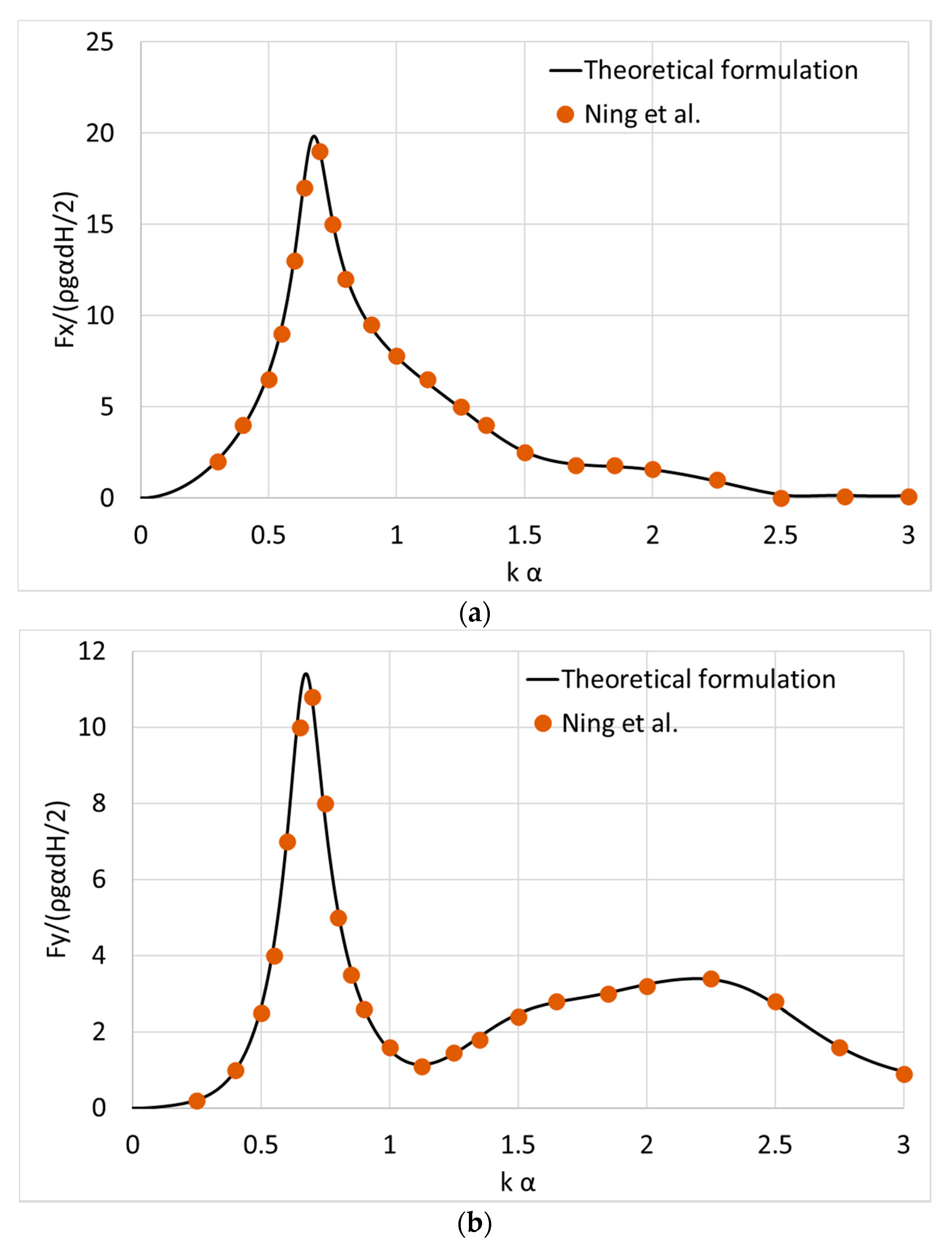
This subsection is dedicated to validation of the presented theoretical formulation with available data from the literature. Herein, a bottom seated vertical cylinder is assumed placed in front of an orthogonal, bottom seated, and surface piercing breakwater. The cylindrical body is of radius α, whereas its distances from the vertical walls equal to L1 = L2 = 1.2α (see Figure 1c,d, assuming h1 = d). The water depth equals to d/α = 1.0 and the wave heading angle β = π/6. In Figure 3, the horizontal exciting wave forces on the cylinder at the x and y directions are presented and compared with the outcomes from [36] with excellent correlation.
4.2. Test Cases
The theoretical methodology developed in the present manuscript was applied for two types of WECs placed in front of an orthogonal breakwater, namely a heaving point absorber, allowed to oscillate only in heave direction and an oscillating water column device, restrained to the wave impact (i.e., no motions were considered). The examined heaving device was of radius α and draught ; floating in water depth d = 7.14α. The center of gravity lay at 0.485α above the keel line and the radius of gyration was 0.742α. The WEC’s mass was equal to its displaced water volume, whereas the was equal to the heave radiation damping of a similar isolated WEC at its heave natural frequency. Additional stiffness due to moorings was not considered in the present manuscript. Concerning the OWC device, it had an outer radius α; inner radius α/b = 1.25; draught ; floating also in water depth d = 7.14α. For the shake of comparisons of numerical results with the heaving device case, the OWC’s air turbine characteristics were considered equal to the Λopt value of a similar OWC in isolation condition at the pumping resonance wave frequency [18]. Furthermore, the distances between the center of both examined WEC and the vertical walls were assumed equal, i.e., L1 = L2 (see Figure 1 and Figure 2). Nevertheless, the method of images can be applied to random L1, L2 values.
The numerical results based on the presented theoretical methodology were obtained using the in-house developed computer code HAMVAB (Hydrodynamic Analysis of Multiple Vertical Axisymmetric Bodies [46]) in FORTRAN programming language. This frequency domain software which relies on analytical representations of the velocity potential around each examined WEC, was preferred against other available numerical tools applicable to general 3D geometries to reduce the computational cost while keeping the same accuracy [39,42].
In the below subsections the absorbed wave power by the WECs is presented for several values of examined: (a) wave heading angles; (b) distances between the device and the breakwater; (c) device’s draught; and (d) breakwater’s length.
4.3. Effect of the Distance between the WEC and the Breakwater
In the present subsection, the effect of the distance between the breakwater and the examined WEC on its efficiency is presented. Herein the examined distances were equal to: L1 = L2 = 1.2α, 2α, 3α, 4α, 5α, 6α, 7α, 8α, 9α and the examined wave heading angles were equal to β = π/6, π/4. Due to symmetry reasons, the β = π/6 case was equal to the β = π/3 case. The draught of both WECs (i.e., heaving device and OWC) were equal to
Based on the presented theoretical formulation, the heave natural frequency of the same WEC in the open sea (i.e., no presence of the breakwater), for α = 1 m, equaled 2.54 (rad/s) and the corresponding heave radiation damping of the converter equaled 0.85 (t/s) ( [t/s]). Similarly, the pumping frequency of the water column inside the oscillating chamber was equal to 2.6 (rad/s) and the corresponding air turbine coefficient inside the OWC equals to 12.62 (m5/(kN·s)).
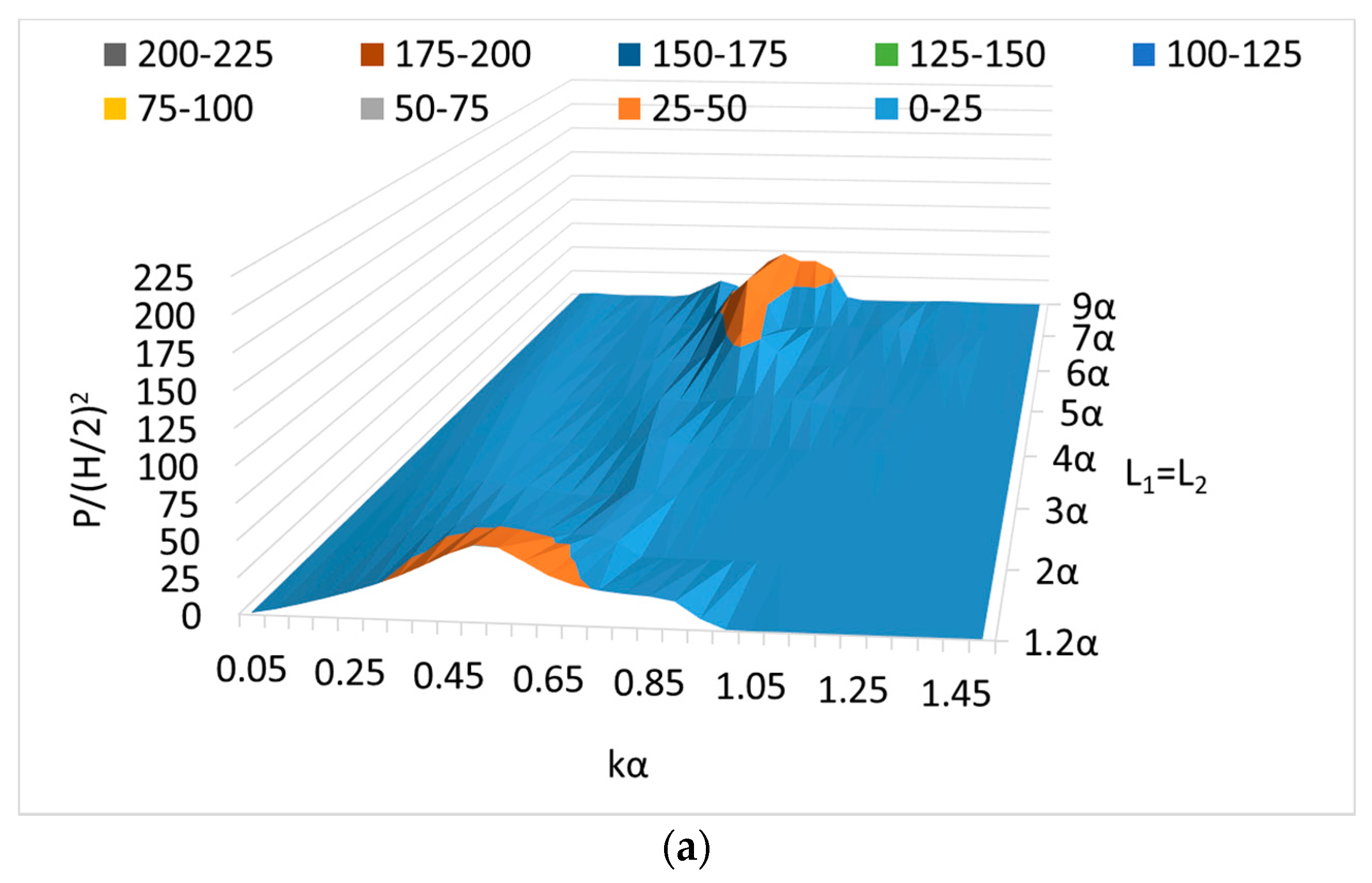
Figure 4 depicts the wave power (P(ω)/(H/2)2 (kW/m2)) absorbed by the heaving device for various examined kα values in the range of kα [0.05, 1.5] and distances between the breakwater and the WEC in the range of L1 = L2 [1.2α, 9α] for wave heading angles β = π/6, π/4. Similarly, in Figure 5 the corresponding absorbed wave power by the OWC device is presented for the same, as above, range of kα and Li, i = 1, 2 values, for β = π/6, π/4.
It is illustrated in Figure 4 that the absorbed wave power by the heaving device is affected by the distance between the device and the walls of the breakwater, as well as by the wave heading angle. Specifically, the absorbed wave power is enhanced at some wave numbers and moderated at other values of kα when the incident wave angle increases. For wave heading angle β = π/6 (and π/3) (see Figure 4a), the wave interaction phenomena between the WEC and the vertical walls have a constructive effect on the device’s hydrodynamic efficiency when the device is placed near the walls (i.e., 1.2α case). The same is true for the cases of the larger distances of the WEC from the breakwater (i.e., 6α; 7α; 9α cases). However, this is not the case at every examined wave frequency (i.e., wave number). It is depicted that the device operates efficiently, i.e., concerning the absorbed wave power, at wave numbers in the range of kα [0.2, 1], whereas the breakwaters’ constructive effect on the device’s hydrodynamic efficiency is increased significantly near the device’s natural frequency, ω = 2.54 rad/s (i.e., kα = 0.65). Additionally, it can be seen that for the close-to-wall cases (i.e., L1 = L2 = 1.2α) the absorbed wave power attains comparable values regardless the wave heading angle (see Figure 4a,b), leading to the conclusion that when the WEC is placed near the walls its efficiency seems to be unaffected by the angle of the incoming wave. In contrast, the value of the absorbed wave power for the far-to-wall cases (i.e., L1 = L2 = 6α; 7α; 9α) increases significantly for β = π/4, compared to the corresponding values for β = π/6 (Figure 4b).
As far as the OWC in front of an orthogonal breakwater is concerned, Figure 5 shows the comparison of P(ω), see Equation (31), for several examined wall-to-body distances and wave heading angles. We arrived at a similar conclusion for the examined heaving device as regards the wave numbers in which the device operates effectively, i.e., kα [0.2, 1], as well as the wave number in the neighbourhood of which the absorbed wave power maximizes, i.e., kα ≈ 0.68. However, in the OWC case, this wave number (i.e., ω = 2.6 rad/s) corresponds to the inner water surface pumping resonance frequency and not to the device’s natural frequency as in the heaving device case. Furthermore, from Figure 5a,b it can be seen that similar to the heaving configuration, for the close-to-wall case (i.e., L1 = L2 = 1.2α), the absorbed wave power remained unaffected by the wave heading angles. On the other hand, at larger distances between the OWC and the walls (i.e., L1 = L2 = 6α; 7α; 9α) the hydrodynamic efficiency was significantly affected by the angle β, presenting amplified values at β = π/4.
Concluding, it is worth mentioning that the selected WEC arrangements (i.e., heaving and OWC device) operate optimally at the neighbourhood of kα ≈ 0.65 and 0.68 which correspond to the heaving device natural frequency and to the OWC pumping frequency, respectively. Furthermore, concerning the optimum distance between the WEC and the vertical walls, it can be obtained that in both WEC configurations the wave interaction effects have a constructive effect on the devices’ absorbed wave power for the close-to-wall and the far-to-wall examined distance cases. As far as the comparison of the hydrodynamic efficiency of the examined WECs is concerned, it can be derived that the heaving and the OWC devices attain comparable results and follow a similar variation pattern concerning the absorbed wave power at every examined distance from the vertical walls. This is also amplified by the fact that the heaving device’s natural frequency and the OWC’s pumping resonance frequency, at which the WECs operate effectively, are located at adjacent wave frequencies (i.e., around kα ≈ 0.66).
4.4. Effect of the WEC’s Draught
In this subsection, the effect of the WECs’ draught on their wave power absorption is examined. The two arrangements of WECs (i.e., heaving and OWC device) were assumed, as in the previous subsection, and placed in front of a fully reflecting orthogonal breakwater of infinite length. The examined WECs’ draughts equal to h1 = 1.2α, 1α, 0.8α, 0.6α, 0.4α, and the wave heading angles β = π/6, π/4. The remaining geometric characteristics of the devices were kept the same as before (see Section 4.2) whereas the distances between the device and the vertical walls equal to L1 = L2 = 1.2α. Due to the variation of the heaving device’s draught, and consequently of its natural frequency, the PTO damping terms for each draught h1 = 1.2α, 1α, 0.8α, 0.6α, 0.4α, assuming α = 1 m, equal to [t/s], respectively. Similarly, the air turbine characteristics for the OWC device equal to: Λ = 12.81; 12.62; 10.85; 8.76; 7.00 (m5/(kN.s)) for each examined draught h1 = 1.2α, 1α, 0.8α, 0.6α, 0.4α, respectively, for α = 1 m.
Figure 6 and Figure 7 depict the absorbed wave power, (P(ω)/(H/2)2 (kW/m2)), by the heaving and the OWC device, respectively, for various examined kα values (i.e., in the range of kα [0.05, 1.5]); devices’ draught and wave heading angles. Specifically, in Figure 6 the heaving device’s hydrodynamic efficiency is presented for several h1 values and for β = π/6, π/4. From the depicted results, it can be seen that the values of P(ω) attain maxima at the neighbourhood of the floater’s natural frequency. In particular, as the floater’s draught increases the observed maximization of the absorbed wave power is shifted at lower values of ka, similar to the WEC’s natural frequencies which they are also shifted at lower values as the draught increases. Furthermore, the wave heading angle seems not to affect the floater’s hydrodynamic efficiency since both β = π/6, π/4 cases attain comparable results.
Figure 7 depicts the OWC’s hydrodynamic efficiency for several wave frequencies (i.e., kα values), device’s draughts, and wave heading angles. It is apparent that the efficiency of the device in front of an orthogonal breakwater attains higher values for h1 = 1.2α, 1α, at every examined wave heading angle, compared to the corresponding values for the remaining examined draughts (i.e., 0.8α, 0.6α, 0.4α). Moreover, the device’s absorbed wave power seems to be unaffected by the wave heading angle attaining similar values for every examined β. Furthermore, it can be observed from the figures that the wave frequencies in which the absorbed power maximizes did not remain constant regardless of the floater’s draught. This was the case in Section 4.3, where different values of distances between the WEC and the walls were examined. Herein, however, the observed maxima are shifted to higher wave numbers as the floater’s draught decreases since the values of the OWC’s pumping frequency are increased as the draught values decrease. Finally, comparing the hydrodynamic efficiency of the examined WECs, it can be concluded that both devices are equally efficient in wave energy absorption for h1 = 1.2α, 1α, at every examined wave heading angle. However, as h1 decreases the OWC’s efficiency, at wave numbers in the neighborhood of kα ≈ 0.68 (i.e., OWCs pumping resonance frequency) appears to be enhanced compared to its heaving device’s counterpart at wave numbers adjacent to its natural frequency.
4.5. Effect of the Breakwater Type
In this subsection, the hydrodynamic efficiency of the two examined WEC-breakwater arrangements (i.e., heaving and OWC device in front of an orthogonal breakwater) is compared for different types of breakwaters. Specifically, apart from the presented orthogonal breakwater, a vane-type (i.e., linear) breakwater is also assumed in order to study the breakwater’s type impact on the device’s efficiency. The considered WEC configurations in front of an orthogonal breakwater were presented in Section 4.2, assuming also h1 = α and L1 = L2 = 1.2α. The corresponding PTO damping characteristics for the heaving device and the air turbine coefficients for the OWC were also presented in Section 4.3, for α = 1 m. Concerning the vane-type breakwater, the two WEC configurations are considered placed in front of a bottom seated, surface piercing, vertical wall of infinite length. The vertical barrier is assumed to be placed along the y axis, whereas the considered wave heading angle β = π/3.
For the evaluation of the WEC’s hydrodynamic efficiency in the case of a linear wall, the method of images was also applied. As in the orthogonal-wall case, the problem under investigation (i.e., a single WEC in front of a linear wall) corresponds to an array of two WECs, i.e., the initial device and its mirror body with respect to the linear breakwater, that are exposed to the action of two-directional surface waves (i.e., one propagating at angle β, a second at angle 180 − β), without the existence of the breakwater.
In Figure 8 the absorbed wave power, (P(ω)/(H/2)2 (kW/m2)), by the heaving and the OWC devices for various examined kα values in the range of kα [0.05, 1.5] is depicted for the two wall cases, i.e., orthogonal and linear breakwater; for L1 = L2 = 1.2α and π/3. The results are compared with the corresponding efficiency of the same WECs in unbounded water. It can be seen that the utilization of a heaving device does not introduce significant differences in the values and the variation patterns of the absorbed wave power compared to the OWC case. Specifically, it can be seen that for small wave numbers (i.e., kα < 0.6) the heaving device in front of an orthogonal breakwater seems to be more efficient than the OWC, attaining larger values of absorbed power. On the contrary, the absorbed wave power by both WECs attains comparable values for kα in the range of kα [0.6, 0.8], whereas for higher values of kα the orthogonal breakwater does not seem to affect the WECs’ efficiency, the latter being tending to the one of a WEC in unbounded water. In addition, it is worthwhile to note the constructive effect the orthogonal breakwater has on the WECs’ hydrodynamic efficiency compared to the no wall case in all the examined kα values.
Figure 8 also presents the comparisons between the absorbed power by the heaving and the OWC converter for the orthogonal and linear breakwater case. It can be noted that the hydrodynamic efficiency of the two examined converters when placed in front of an orthogonal breakwater is significantly amplified compared to the vane-breakwater case. Consequently, among the examined wall and no-wall cases, the orthogonal breakwater is considered to be the most efficient case in terms of the WECs’ wave power absorption enhancement.
4.6. Effect of the Walls’ Length
In the present theoretical analysis, a fully reflecting, vertical, bottom fixed, surface piercing, orthogonal breakwater of infinite length is assumed in order to apply the method of images to the examined WEC orthogonal breakwater system. Herein, the theoretical results are compared with the corresponding numerical outcomes derived from the numerical analysis of an orthogonal breakwater of finite length. The analysis relies on the boundary integral equation method for the velocity potential representation around the breakwater and the WEC, which is numerically realized using the panel software HAQi [47] for the examined finite length cases, using the sink-source technique as presented in [48,49,50].
The examined WEC is a heaving device, of radius α and draught ; floating in water depth d = α. The center of gravity lies at 0.485α above the keel line and the radius of gyration is 0.742α, whereas the PTO damping coefficient equals to zero. The distance between the centre of the floater and the vertical wall equals to L = 1.5α. The WEC’s and breakwaters’ surfaces have been discretized into 4920 elements (i.e., 840 elements for the converter’s simulation, whereas 4080 elements have been used for the vertical walls’ simulation, see Figure 9). Finally, the examined walls’ length equal to 50α and the wave heading angles β = π/6; π/4.
Figure 10 and Figure 11 depict the heave exciting forces and the heave hydrodynamic coefficients (i.e., as being presented in Equation (19)), respectively, of the heaving device when placed in front an orthogonal wall of length 50α, for β = π/6; π/4. The results are compared with the infinite walls’ length case. The exciting forces are non-dimensionalized by (ρgα2(H/2)), whereas the added mass and damping coefficients by (ρα3) and (ρωα3), respectively.
It can be seen that the consideration of a fully reflecting orthogonal breakwater (i.e., infinite walls’ length) leads to an overestimation of the values of the heave exciting forces at small wave numbers. Specifically, for wave numbers tending to zero the values of Fz begin their variation from 4π, whereas for the finite walls-length case the values of the heave exciting forces tend to the limiting value of π. On the contrary, as the wave number increases the results of the infinite- and finite-length cases convergence. Furthermore, it should be noted that the deviation of the results due to the walls’ length in the low wave numbers is presented regardless the wave heading angle (see Figure 11a,b). Concerning the WEC’s hydrodynamic coefficients, presented in Figure 11, the walls’ length seems not to affect the floater’s added mass in heave direction since the examined length-cases (i.e., 50α, infinite length-cases) attain similar results. On the other hand, the infinite walls’ length assumption overestimates the results of the converter’s heave damping coefficients at low wave numbers compared to the results from the finite length case.
In Figure 12, the WEC’s heave displacement, non-dimensionalized by the factor (H/2), is presented for the two examined walls’ length cases i.e., 50α and infinite length-cases, for β = π/6; π/4. It can be noted that the values of heave displacement also attain deviations at small wave numbers for the finite examined walls’ length case, compared to the infinite-length case, regardless of the wave heading angle. This phenomenon is due to the obtained differences in Fz and b33 between the infinite- and finite-length cases (see Figure 10 and Figure 11). Therefore, it can be concluded that the infinite wall assumption has limitations concerning the accurate estimation of the floater’s heave exciting forces, damping coefficients and heave displacements at small wave frequencies, since the method of images seems to overestimate these values. This overestimation is notable at every examined wave heading angle.
Another limitation on the method of images concerns the wave heading angles β = 0, π/2. In these angles, the incoming wave is reflected only by one arm of the wall, i.e., along the y- or x-axis, respectively. Therefore, only two wave trains are considered, i.e., 0 (or π/2) and π (or 3π/2) for the solution of the diffraction problem. Figure 13 depicts the heave exciting forces on the examined heaving device for the two walls’ length cases, i.e., infinite- and finite-length, for a zero wave heading angle. The examined walls’ length equals to 50α. It can be noted that the values of the exciting forces attain lower values compared to the corresponding values for β = π/3, π/4 (see Figure 10). Furthermore, for kα tending to zero the values of the exciting forces for the infinite length case tend to 2π, whereas their corresponding counterparts for the finite length case, tend to π. Nevertheless, the results from the two walls’ length cases converge for higher wave numbers.
5. Conclusions
This study investigates the efficiency of a WEC placed in front of a bottom-seated, surface piercing, vertical orthogonal breakwater in the frequency domain. A theoretical methodology based on the image method has been applied to simulate the effect of the walls on the device’s power absorption considering infinite length of the walls’ arms. Furthermore, the effect of an orthogonal breakwater of finite length on the WEC’s efficiency has been numerically investigated.
Two different types of WECs have been studied, namely the heaving device and the oscillating water column device. Emphasis is placed on the effect of: (a) the converters’ distance from the walls; (b) the converters’ draught; (c) the breakwaters’ type; and (d) the breakwaters’ length on the devices’ absorbed wave power. Based on the theoretical results shown and discussed in the dedicated sections, the present research contribution concerns the enhancement of the harvested wave power by the WEC in front of an orthogonal wall when compared to the absorbed wave power by the same WEC in the open sea or when placed in front of a vane-type breakwater. This efficiency amplification is strongly dependent on the distance between the converter and the walls, the floater’s draught, the examined wave number, and the wave heading angle. On top of that, it is shown that the assumption of a fully reflecting breakwater of infinite length dictates by a large expense the floater’s exciting wave loads, hydrodynamic characteristics, and as a result the body’s heave displacement, compared to the effect that an orthogonal wall of finite length may have on these parameters, especially at small wave numbers. At these wave numbers, the infinite wall assumption causes an overestimation of the heave exciting forces and damping coefficients. Nevertheless, careful use of the method of images is recommended, since these deviations between the finite- and infinite-length wall cases appear at small wave frequencies, whereas at higher values of kα the results of the two length-cases correlates.
The present study will be further continued by determining in detail the hydrodynamic characteristics of an array of cylindrical floaters allowed to move in their six-degrees of freedom, located in front of a V-shaped breakwater of a random angle.
Author Contributions
Conceptualization, S.A.M. and D.N.K.; methodology, S.A.M.; software, S.A.M. and D.N.K.; validation, S.A.M. and D.N.K.; investigation, S.A.M.; writing—original draft preparation, D.N.K.; writing—review and editing, S.A.M.; visualization, D.N.K.; supervision, S.A.M. All authors have read and agreed to the published version of the manuscript.
Funding
This research received no external funding.
Institutional Review Board Statement
Not applicable.
Informed Consent Statement
Not applicable.
Data Availability Statement
Not applicable.
Conflicts of Interest
The authors declare no conflict of interest.
Nomenclature
| d | Water depth |
| ω | Wave frequency |
| H | Wave height |
| β | Wave heading angle |
| rk,θk,zk | Local co-ordinate system of the k WEC |
| Lk, k = 1, 2 | Distance between the WEC and the vertical walls |
| α | WEC’s radius |
| h1 | WEC’s draught |
| b | OWC’s inner radius |
| Φ | Velocity potential |
| Velocity potential of the undisturbed incident harmonic wave | |
| Scattered velocity potential for the q WEC | |
| Radiation velocity potential resulting from the forced p body motion in heave | |
| Diffraction velocity potential for the q WEC | |
| Velocity amplitude in heave direction of the p heaving device | |
| Radiation velocity potential resulting from the inner air pressure in p OWC | |
| Amplitude of the oscillating pressure head in the chamber of the p OWC | |
| g | Acceleration due to gravity |
| ρ | Water density |
| I | The infinite ring element around the q WEC |
| III | The ring element below the q WEC |
| M | The ring element inside the chamber of the q OWC |
| Unit normal vector | |
| δq,p | Kronecker’s symbol |
| Generalized normal component | |
| Diffraction coefficient | |
| Motion radiation coefficient | |
| Pressure radiation coefficient | |
| Orthonormal function | |
| m-th order Bessel function of the first kind | |
| Polar coordinates of the q converter center relative to the origin O of the global co-ordinate systems O-xyz | |
| Heave exciting forces on WEC | |
| Heave exciting force on the WEC, for | |
| Mean wetted surface of the q WEC | |
| Motion hydrodynamic forces | |
| Added mass and damping coefficients | |
| Added mass and damping coefficient of the initial WEC in the i-th direction, due to the forced oscillation of the n body, n = 1, 2, 3, 4 in heave direction | |
| Pressure hydrodynamic forces | |
| Pressure dependent hydrodynamic coefficients | |
| Pressure hydrodynamic coefficients of the OWC in the i-th direction, due to the unit air pressure inside the n device, n = 1, 2, 3, 4 | |
| Air volume flow | |
| Vertical velocity of the water surface in the OWC | |
| Water surface cross-sectional area inside the OWC | |
| Diffraction volume flow | |
| Pressure-dependent volume flow | |
| Diffraction volume flow for | |
| Pressure-dependent volume flow due to the unit air pressure inside the p device | |
| Λ | Complex pneumatic admittance (air turbine coefficient) |
| Complex pneumatic admittance optimum value | |
| m | Mass of the heaving device |
| PTO damping coefficient | |
| Hydrostatic stiffness coefficient | |
| Wave power absorbed by the WEC |
References
- Available online: https://www.oceanenergy-europe.eu/ocean-energy/ (accessed on 2 October 2020).
- Badcock-Broe, A.; Flynn, R.; George, S.; Gruet, R.; Medic, N. Wave and Tidal Energy Market Deployment Strategy for Europe, Strategic Initiative for Ocean Energy (SI Ocean). 2014. Available online: http://www.siocean.eu/en/MarketDeployment/Market-Deployment-Strategy/ (accessed on 2 October 2020).
- IRENA. Renewable Power Generation Costs in 2018; International Renewable Energy Agency: Abu Dhabi, UAE, 2019. [Google Scholar]
- MacGillivray, A.; Jeffrey, H.; Hanmer, C.; Magagna, D.; Raventos, A.; Badcock-Broe, A. Ocean Energy Technology: Gaps and Barriers. SI Ocean Project Supported by the Intelligent Energy Europe Programme of European Union. 2013. Available online: www.si-ocean.eu (accessed on 1 September 2020).
- Mustapa, M.A.; Yaakob, O.B.; Ahmed, Y.M.M.; Rheem, C.K.; Koh, K.K.; Faizul, A.A. Wave energy device and breakwater integration: A review. Renew. Sustain. Energy Rev. 2017, 77, 43–58. [Google Scholar] [CrossRef]
- Rajendra, K.; Balaji, R.; Mukul, P. Review of Indian research on innovative breakwaters. Geo Mar. Sci. 2017, 46, 431–452. [Google Scholar]
- Zhao, X.L.; Ning, D.Z.; Liang, D.F. Experimental investigation on hydrodynamic performance of a breakwater-integrated WEC system. Ocean Eng. 2019, 171, 25–32. [Google Scholar] [CrossRef]
- Zheng, S.; Zhang, Y.; Iglesias, G. Coast/breakwater-integrated OWC: A theoretical model. Mar. Struct. 2019, 66. [Google Scholar] [CrossRef]
- Cascajo, R.; Garcia, E.; Quiles, E.; Correcher, A.; Morant, F. Integration of marine wave energy converters into seaports: A case study in port of Valencia. Energies 2019, 12, 787. [Google Scholar] [CrossRef] [Green Version]
- Cabral, T.; Clemente, D.; Rosa-Santos, P.; Taveira-Pinto, F.; Morais, T.; Belga, F.; Cestaro, H. Performance Assessment of a Hybrid Wave Energy Converter Integrated into a Harbor Breakwater. Energies 2020, 13, 236. [Google Scholar] [CrossRef] [Green Version]
- Zhao, X.L.; Ning, D.; Zou, Q.P.; Qiao, D.S.; Cai, S.Q. Hybrid floating breakwater-WEC system: A review. Ocean Eng. 2019, 186. [Google Scholar] [CrossRef]
- Howe, D.; Nader, J.R.; Macfarlane, G. Performance analysis of a floating breakwater integrated with multiple oscillating water column wave energy converters in regular and irregular seas. Appl. Ocean Res. 2020, 99, 102147. [Google Scholar] [CrossRef]
- Howe, D.; Nader, J.R.; Macfarlane, G. Experimental investigation of multiple oscillating water column wave energy converters integrated in a floating breakwater: Energy extraction performance. Appl. Ocean Res. 2020, 97, 102086. [Google Scholar] [CrossRef]
- Tay, Z.Y. Performance and wave impact of an integrated multi-raft wave energy converter with floating breakwater for tropical climate. Ocean Eng. 2020, 218. [Google Scholar] [CrossRef]
- Zhao, X.; Zhang, Y.; Li, M.; Johanning, L. Hydrodynamic performance of a comb-type breakwater-WEC system. An analytical study. Renew. Energy 2020, 159. [Google Scholar] [CrossRef]
- Zhao, X.; Xue, R.; Geng, J.; Goteman, M. Analytical investigation on the hydrodynamic performance of a multi-pontoon breakwater-WEC system. Ocean Eng. 2011, 220. [Google Scholar] [CrossRef]
- Guo, B.; Wang, R.; Ning, D.; Chen, L.; Sulisz, W. Hydrodynamic performance of a novel WEC-breakwater integrated system consisting of triple dual-freedom pontoons. Energy 2020, 209. [Google Scholar] [CrossRef]
- Konispoliatis, D.; Mavrakos, S. Theoretical performance investigation of a vertical cylindrical oscillating water column device in front of a vertical breakwater. J. Ocean Eng. Mar. Energy 2019. [Google Scholar] [CrossRef]
- Konispoliatis, D.; Mavrakos, S.A.; Soukissian, T.H. Array of oscillating water column devices in front of a vertical breakwater in the Mediterranean Sea. In Proceedings of the 12th International Conference on Deregulated Electricity Market Issues in Southern Eastern Europe (DEMSEE 2019), Herakleion, Crete, 19–20 September 2019. [Google Scholar]
- Zhang, C.; Ning, D. Hydrodynamic study of a novel breakwater with parabolic openings for wave energy harvest. Ocean Eng. 2019, 182. [Google Scholar] [CrossRef]
- Konispoliatis, D.N.; Chatjigeorgiou, I.K.; Mavrakos, S.A. Near trapped wave phenomena in an array of truncated cylinders in a perpendicular arrangement in front of a vertical breakwater. Appl. Math. Model. 2020, 83, 497–525. [Google Scholar] [CrossRef]
- Konispoliatis, D.N.; Mavrakos, S.A.; Katsaounis, G.M. Theoretical evaluation of the hydrodynamic characteristics of arrays of vertical axisymmetric floater of arbitrary shape in front of a vertical breakwater. J. Mar. Sci. Eng. 2020, 8, 62. [Google Scholar] [CrossRef] [Green Version]
- Konispoliatis, D.N.; Mavrakos, S.A. Wave power absorption by arrays of wave energy converters in front of a vertical breakwater: A theoretical study. Energies 2020, 13, 1985. [Google Scholar] [CrossRef] [Green Version]
- Yeung, R.W.; Sphaier, S.H. Wave-interference effects on a truncated cylinder in a channel. J. Eng. Math. 1989, 23, 95–117. [Google Scholar] [CrossRef]
- Mavrakos, S.A. The scattered wave field by vertical cylinders in a narrow tank. In Proceedings of the 4th National Symposium on Theoretical and Applied Mechanics, Xanthi, Greece, 26–29 June 1995; Volume II, pp. 819–829. [Google Scholar]
- Masuda, Y. Apparatus for Generating Electrical Power by Wave Energy and Dissipating Waves. Netherlands Patent GB1,492,427, 16 November 1977. [Google Scholar]
- Reslo, D.T.; Briggs, M.J.; Fowler, J.E.; Markle, D.G. Floating “V” Shaped Breakwater. U.S. Patent 005,702,203A, 30 December 1997. [Google Scholar]
- Briggs, M. Performance Characteristics of a Rapidly Installed Breakwater System; ERDC/CHL TR-01-13; U.S. Army Engineer Research and Development Center: Vicksburg, MS, USA, 2001; p. 248. [Google Scholar]
- Briggs, M.; Ye, W.; Demirbilek, Z.; Zhang, J. Field and numerical comparisons of the RIBS floating breakwater. J. Hydraul. Res. 2002, 40, 289–301. [Google Scholar] [CrossRef]
- Miao, G.P.; Cheng, J.S.; You, Y.X.; Wang, J.Q. Wave defending effects of V-type bottom-mounted breakwaters. China Ocean Eng. 2005, 19, 195–204. [Google Scholar]
- Chang, K.H.; Tsaur, D.H.; Huang, L.H. Accurate solution to diffraction around a modified V-shaped breakwater. Coast. Eng. 2012, 68, 56–66. [Google Scholar] [CrossRef]
- Ding, N.; Yu, J.; Hou, J. Characteristics of dynamic pressure on floating V-shaped breakwater. J. Drain. Irrig. Mach. Eng. 2014, 32, 29–32. [Google Scholar]
- Yu, Y.; Ding, N.; Hou, J. Wave pressure acting on V-shaped floating breakwater in random seas. J. Ocean Univ. China 2015, 14, 975–981. [Google Scholar] [CrossRef]
- Retief, G.; Muller, F.; Prestedge, G. Detailed design of a wave energy conversion plant. In Proceedings of the 19th Conference on Coastal Engineering, Houston, TX, USA, 3–7 September 1984. [Google Scholar]
- Kelly, T.; Dooley, T.; Campbell, J.; Ringwood, J.V. Comparison of the experimental and numerical results of modelling a 32-oscillating water column, V-shaped floating wave energy converter. Energies 2013, 6, 4045–4077. [Google Scholar] [CrossRef] [Green Version]
- Ning, D.; Teng, B.; Song, X. Analytical study on wave diffraction from a vertical circular cylinder in front of orthogonal vertical walls. Mar. Sci. Bull. 2005, 7, 1–9. [Google Scholar]
- Ning, D.; Teng, B. Study on the oscillation of a uniform cylinder in front of two vertical walls intersecting normally. Chin. Eng. Sci. 2003, 5, 84–91. [Google Scholar]
- Konispoliatis, D.; Mavrakos, S. Theoretical analysis of a vertical cylindrical floater in front of an orthogonal breakwater. Fluids 2020, 5, 135. [Google Scholar] [CrossRef]
- Konispoliatis, D.; Mavrakos, S. Hydrodynamic analysis of an array of interacting free-floating oscillating water column (OWC’s) devices. Ocean Eng. 2016, 111, 179–197. [Google Scholar] [CrossRef]
- Falnes, J. Ocean Waves and Oscillating Systems; Cambridge University Press: Cambridge, UK, 2002. [Google Scholar]
- Okhusu, M. Hydrodynamic forces on multiple cylinders in waves. In Proceedings of the International Symposium on the Dynamics of Marine Vehicles and Structures in Waves, London, UK, 1–5 April 1974. [Google Scholar]
- Mavrakos, S.A.; McIver, P. Comparison of methods for computing hydrodynamic characteristics of arrays of wave power devices. Appl. Ocean Res. 1997, 19, 283–291. [Google Scholar] [CrossRef]
- Mavrakos, S.A. Hydrodynamic coefficients for groups of interacting vertical axisymmetric bodies. Ocean Eng. 1991, 18, 485–515. [Google Scholar] [CrossRef]
- Sarmento, A.J.N.A.; Falcao, A.F.O. Wave generation by an oscillating surface-pressure and its application in wave-energy extraction. J. Fluid Mech. 1985, 150, 467–485. [Google Scholar] [CrossRef]
- Evans, D.V.; Porter, R. Efficient calculation of hydrodynamic properties of O.W.C type devices. In Proceedings of the 15th Offshore Mechanics and Arctic Engineering (OMAE 1996), Part B, Florence, Italy, 16–20 June 1996; pp. 123–132. [Google Scholar]
- Mavrakos, S.A. Users Manual for the Software HAMVAB; Laboratory for Floating Bodies and Mooring Systems, National Technical University of Athens, 1995; Available online: https://www.researchgate.net/publication/325673648_Development_of_a_Multi-purpose_Floating_structure_for_the_Exploitation_of_Offshore_Wind_and_Wave_Resources (accessed on 11 January 2021).
- Bardis, L.; Mavrakos, S.A. User’s Manual for the Computer Code HAQ; Laboratory for Floating Bodies and Mooring Systems, National Technical University of Athens, 1988; Available online: https://www.researchgate.net/publication/305411793_First_and_second_order_hydrodynamic_effects_and_wave_run-_up_on_a_four_cylinder_configuration_at_small_forward_speed (accessed on 11 January 2021).
- Wehausen, J.V.; Laitone, E.V. Surface waves. In Encyclopedia of Physics; Springer: Berlin/Heidelberg, Germany, 1960; Volume 9. [Google Scholar]
- Garrison, C.J. Hydrodynamics of a large objects on the sea. Part I: Hydrodynamic analysis. J. Hydronautics 1974, 8, 5–12. [Google Scholar] [CrossRef]
- Garrison, C.J. Hydrodynamics of a large objects on the sea. Part II: Motion of free floating bodies. J. Hydronautics 1975, 9, 58–63. [Google Scholar] [CrossRef]
Figure 1.
Three-dimensional (3D) and two-dimensional (2D) representations of a wave energy converter (WEC) in front of an orthogonal breakwater: (a) oscillating water column (OWC) side view—xyz in 3D; (b) OWC side view—xz in 2D; (c) heaving device side view—xyz in 3D; (d) heaving device side view—xz in 2D.

Figure 2.
3D representations of a WEC-breakwater system applying the method of images: (a) side view of an array of four OWCs (i.e., one initial and three image devices); (b) side view of an array of four heaving devices (i.e., one initial and three image devices).
Figure 2.
3D representations of a WEC-breakwater system applying the method of images: (a) side view of an array of four OWCs (i.e., one initial and three image devices); (b) side view of an array of four heaving devices (i.e., one initial and three image devices).

Figure 3.
Horizontal exciting wave forces on a bottom seated cylinder in front of an orthogonal breakwater: (a) exciting forces on x-axis; (b) exciting forces on y-axis. The results are non-dimensionalized by the factor ρgdα(H/2) and compared with the results from [36].
Figure 3.
Horizontal exciting wave forces on a bottom seated cylinder in front of an orthogonal breakwater: (a) exciting forces on x-axis; (b) exciting forces on y-axis. The results are non-dimensionalized by the factor ρgdα(H/2) and compared with the results from [36].

Figure 4.
Heaving device’s absorbed wave power, P(ω)/(H/2)2 (kW/m2), versus kα for various examined distances between the device and the orthogonal walls and wave heading angles: (a) β = π/6; (b) β = π/4. Here α = 1 m.
Figure 4.
Heaving device’s absorbed wave power, P(ω)/(H/2)2 (kW/m2), versus kα for various examined distances between the device and the orthogonal walls and wave heading angles: (a) β = π/6; (b) β = π/4. Here α = 1 m.


Figure 5.
OWC’s absorbed wave power P(ω)/(H/2)2 (kW/m2), versus kα for various examined distances between the device and the orthogonal walls and wave heading angles: (a) β = π/6; (b) β = π/4. Here α = 1 m.
Figure 5.
OWC’s absorbed wave power P(ω)/(H/2)2 (kW/m2), versus kα for various examined distances between the device and the orthogonal walls and wave heading angles: (a) β = π/6; (b) β = π/4. Here α = 1 m.

Figure 6.
Heaving device’s absorbed wave power P(ω)/(H/2)2 (kW/m2), versus kα for various examined body’s draughts, h1, and wave heading angles: (a) β = π/6; (b) β = π/4. Here α = 1 m.
Figure 6.
Heaving device’s absorbed wave power P(ω)/(H/2)2 (kW/m2), versus kα for various examined body’s draughts, h1, and wave heading angles: (a) β = π/6; (b) β = π/4. Here α = 1 m.

Figure 7.
OWC’s absorbed wave power P(ω)/(H/2)2 (kW/m2), versus kα for various examined body’s draughts, h1, and wave heading angles: (a) β = π/6; (b) β = π/4. Here α = 1 m.
Figure 7.
OWC’s absorbed wave power P(ω)/(H/2)2 (kW/m2), versus kα for various examined body’s draughts, h1, and wave heading angles: (a) β = π/6; (b) β = π/4. Here α = 1 m.

Figure 8.
WEC’s absorbed wave power P(ω)/(H/2)2 (kW/m2), versus kα for various breakwater-cases, i.e., orthogonal wall, linear wall, and no wall case: (a) Heaving device’s absorbed power, (b) OWC’s absorbed power.
Figure 8.
WEC’s absorbed wave power P(ω)/(H/2)2 (kW/m2), versus kα for various breakwater-cases, i.e., orthogonal wall, linear wall, and no wall case: (a) Heaving device’s absorbed power, (b) OWC’s absorbed power.


Figure 9.
Panel discretization of the examined WEC and the orthogonal breakwater.

Figure 10.
Heaving exciting force versus kα for walls’ length equal to 50α, and wave heading angles: (a) β = π/6; (b) β = π/4. The results are compared to the infinite walls’ length case.
Figure 10.
Heaving exciting force versus kα for walls’ length equal to 50α, and wave heading angles: (a) β = π/6; (b) β = π/4. The results are compared to the infinite walls’ length case.


Figure 11.
Device’s heave hydrodynamic coefficients versus kα for walls’ length equal to 50α: (a) a33; (b) b33. The results are compared to the infinite walls’ length case.
Figure 11.
Device’s heave hydrodynamic coefficients versus kα for walls’ length equal to 50α: (a) a33; (b) b33. The results are compared to the infinite walls’ length case.

Figure 12.
Heave displacement of the heaving device versus kα for walls’ length equal to 50α, and wave heading angles: (a) β = π/6; (b) β = π/4. The results are compared to the infinite walls’ length case.
Figure 12.
Heave displacement of the heaving device versus kα for walls’ length equal to 50α, and wave heading angles: (a) β = π/6; (b) β = π/4. The results are compared to the infinite walls’ length case.

Figure 13.
Heaving exciting force versus kα for walls’ length 50α, and wave heading angle β = 0. The results are compared to the infinite walls’ length case.
Figure 13.
Heaving exciting force versus kα for walls’ length 50α, and wave heading angle β = 0. The results are compared to the infinite walls’ length case.

Publisher’s Note: MDPI stays neutral with regard to jurisdictional claims in published maps and institutional affiliations. |
© 2021 by the authors. Licensee MDPI, Basel, Switzerland. This article is an open access article distributed under the terms and conditions of the Creative Commons Attribution (CC BY) license (http://creativecommons.org/licenses/by/4.0/).
Share and Cite
MDPI and ACS Style
Konispoliatis, D.N.; Mavrakos, S.A. Hydrodynamic Efficiency of a Wave Energy Converter in Front of an Orthogonal Breakwater. J. Mar. Sci. Eng. 2021, 9, 94. https://doi.org/10.3390/jmse9010094
AMA Style
Konispoliatis DN, Mavrakos SA. Hydrodynamic Efficiency of a Wave Energy Converter in Front of an Orthogonal Breakwater. Journal of Marine Science and Engineering. 2021; 9(1):94. https://doi.org/10.3390/jmse9010094
Chicago/Turabian StyleKonispoliatis, Dimitrios N., and Spyridon A. Mavrakos. 2021. "Hydrodynamic Efficiency of a Wave Energy Converter in Front of an Orthogonal Breakwater" Journal of Marine Science and Engineering 9, no. 1: 94. https://doi.org/10.3390/jmse9010094
Note that from the first issue of 2016, this journal uses article numbers instead of page numbers. See further details here.