
Numerical Simulation Analysis on the Lateral Dynamic Characteristics of Deepwater Conductor Considering the Pile-Soil Contact Models

Abstract
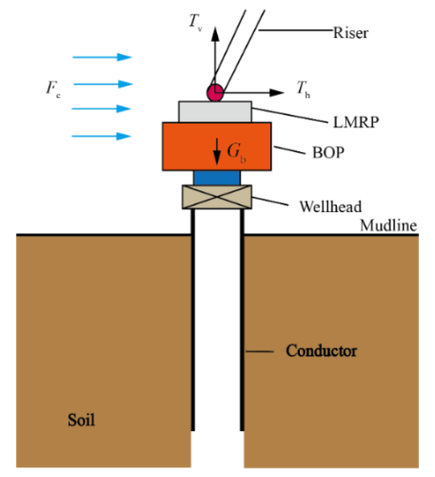
:1. Introduction
2. Pile–Soil Contact Models
2.1. Contact Surface Model
2.1.1. Normal Contact Model
2.1.2. Tangential Contact Model
2.2. Goodman Contact Element Model
3. Numerical Simulation and Discussion
3.1. Numerical Simulation
3.1.1. Modeling Process
Geometric Model
3.1.2. Simulation Results
3.2. Model Validation and Mesh Independence
3.3. Parameter Sensitivity Analysis
3.3.1. Bending Moment on the Top of the Conductor
3.3.2. Wellhead Stick-Up
3.3.3. Geometry of the Conductor
3.3.4. Mechanical Parameters of the Soil
4. Conclusions
- (1)
- The lateral deformation, deflection angle and von Mises stress calculated by the Goodman contact element model are greater than those calculated by the contact surface model. Therefore, we recommend that the Goodman element model should be paid sufficient attention while analyzing the stability of the subsea wellhead during deepwater drilling.
- (2)
- The maximum lateral deformation and bending moment of the conductor decrease with the O.D. and W.T. of the conductor and the cohesion and internal friction angle of the soil, while they increase with the wellhead stick-up. Both the vertical force on the conductor and the soil density have a negligible effect on the lateral response of the conductor.
Author Contributions
Funding
Institutional Review Board Statement
Informed Consent Statement
Data Availability Statement
Acknowledgments
Conflicts of Interest
Nomenclature
| soil cohesion, MPa | |
| damping coefficient of the soil, N/m·s | |
| clearance and pressure on the contact surface, m | |
| bending stiffness, N·m2 | |
| distance between the two contact surfaces, m | |
| normal stiffness coefficient of the contact surface, N/m2 | |
| tangential stiffness coefficient of the contact surface, N/m2 | |
| distance between the two nodes in Goodman element model, m | |
| mass of the conductor per length, kg/m | |
| axial force of the conductor, N | |
| pressure on the contact surface, MPa | |
| time, s | |
| relative displacement of the contact surface, m | |
| conductor depth, m | |
| lateral deformation of the conductor, m | |
| undetermined constant, dimensionless | |
| undetermined constant, dimensionless | |
| tangential relative displacement of the contact surface, m | |
| normal relative displacement of the contact surface, m | |
| normal stress, MPa | |
| normal stress on the contact surface, MPa | |
| shear strength, MPa | |
| relative stress, MPa | |
| tangential stress on the contact surface, MPa | |
| internal friction angle, ° |
References
- Gao, D.L.; Wang, Y.B. Progress in Tubular Mechanics and Design Control Techniques for Deepwater Drilling. Pet. Sci. Bull. 2016, 1, 61–80. [Google Scholar] [CrossRef]
- Sathuvalli, U.B.; Suryanarayana, P.V. Conductor-soil Interaction in Wellhead Motion (WHM) of Platform Wells. In Proceedings of the SPE Western Regional Meeting, Anchorage, AK, USA, 23–26 May 2016; p. SPE-180437-MS. [Google Scholar] [CrossRef]
- Beck, R.D.; Jackson, C.W.; Hamilton, T.K. Reliable Deepwater Structural Casing Installation Using Controlled Jetting. In Proceedings of the SPE Annual Technical Conference and Exhibition, Dallas, TX, USA, 6–9 October 1991; p. SPE-22542-MS. [Google Scholar] [CrossRef]
- Wetmore, S.B.; Halbleib, B.L. Consideration for Design of Drilling Conductors for the New Generation of Deepwater, Harsh Weather Jackups. In Proceedings of the SPE/IADC Drilling Conference, New Orleans, LA, USA, 18–21 February 1992; p. SPE-23856-MS. [Google Scholar] [CrossRef]
- Philippe, J. Innovative Design Method for Deepwater Surface Casings. In Proceedings of the SPE Annual Technical Conference and Exhibition, San Antonio, TX, USA, 29 September–2 October 2002; p. SPE-77357-MS. [Google Scholar] [CrossRef]
- Wang, T.; Sun, B.J. Lateral Bearing Capacity of Jetting Structural Casing of Wellhead in Deepwater. J. China Univ. Pet. 2008, 32, 50–53. [Google Scholar] [CrossRef]
- Guan, Z.C.; Su, K.H.; Su, Y.N. Analysis on Lateral Load Bearing Capacity of Conductor and Surface Casing for Deepwater Drilling. Acta Pet. Sin. 2009, 30, 285–290. [Google Scholar] [CrossRef]
- Akers, T.J. Jetting of Structural Casing in Deepwater Environments: Job Design and Operational Practices. SPE Drill. Complet. 2008, 23, 29–40. [Google Scholar] [CrossRef]
- Su, K.H. Analysis on Mechanical Stability of Subsea Wellhead and Bearing Capacity of Conductor for Deepwater Drilling. Ph.D. Thesis, China University of Petroleum-East China, Dongying, China, 2009. [Google Scholar]
- Tang, H.X.; Luo, J.F.; Ye, J.H.; Chen, W.J.; Chang, Y.J.; Chen, G.M. Method of Design of Conductor Setting Depth for Ultra-deepwater Jetting Drilling in South China Sea. J. Oil Gas Technol. 2011, 33, 147–151. [Google Scholar] [CrossRef]
- Li, C.W. Research on Overall Mechanical Performance of Deepwater Riser-Wellhead-Conductor System. Ph.D. Thesis, China University of Petroleum-Beijing, Beijing, China, 2016. [Google Scholar]
- Deng, S. Research on Stability of Subsea Wellhead-Pipe String in Deepwater Shallow under Earthquake Excitations. Int. J. Numer. Anal. Methods Geomech. 2017, 8, 19–43. [Google Scholar]
- American Petroleum Institute. Recommended Practice for Planning, Designing and Constructing Fixed Offshore Platforms-Working Stress Design; API RP 2A-WSD; American Petroleum Institute: Washington, DC, USA, 2007. [Google Scholar]
- Das, B.; Saha, R.; Haldar, S. Effect of In-Situ Variability of Soil on Seismic Design of Piled Raft Supported Structure Incorporating Dynamic Soil-Structure-Interaction. Dyn. Earthq. Eng. 2016, 84, 251–268. [Google Scholar] [CrossRef]
- Yan, W.; Chen, Z.J.; Deng, J.G.; Zhu, H.Y.; Deng, F.C.; Zheng, L.L. Numerical Method for Subsea Wellhead Stability Analysis in Deepwater Drilling. Ocean Eng. 2015, 98, 50–56. [Google Scholar] [CrossRef]
- Ren, Y.R.; Liu, Y.B.; Gu, X.Y. Analysis for the Interface of the Pipe/Soil Interaction by ABAQUS Software. Mech. Eng. 2004, 6, 43–44. [Google Scholar] [CrossRef]
- Templeton, J.S. Finite Element Analysis of Conductor/Seafloor Interaction. In Proceedings of the Offshore Technology Conference, Houston, TX, USA, 4–7 May 2009; p. OTC-20197-MS. [Google Scholar] [CrossRef]
- Wang, Y.B.; Gao, D.L.; Fang, J. Finite Element Analysis of Deepwater Conductor Bearing Capacity to Analyze the Subsea Wellhead Stability with Consideration of Contact Interface Models Between Pile and Soil. J. Pet. Sci. Eng. 2015, 126, 48–54. [Google Scholar] [CrossRef]
- Nielsen, M.T. Resistance of a Soil Layer to Horizontal Vibration of a Pile. Earthq. Eng. Struct. Dyn. 1983, 10, 497–510. [Google Scholar] [CrossRef]
- Novak, M.; Nogami, T. Soil-pile Interaction in Horizontal Vibration. Earthq. Eng. Struct. Dyn. 1977, 5, 263–281. [Google Scholar] [CrossRef]
- Quirós, G.W.; Little, R.L. Deepwater Soil Properties and Their Impact on the Geotechnical Program. In Proceedings of the Offshore Technology Conference, Houston, TX, USA, 5–8 May 2003; p. OTC-15262-MS. [Google Scholar] [CrossRef]
- Tahghighi, H.; Konagai, K. Numerical Analysis of Nonlinear Soil-Pile Group Interaction under Lateral Loads. Soil Dyn. Earthq. Eng. 2007, 27, 463–474. [Google Scholar] [CrossRef]
- Nogami, T.; Konagai, K. Time Domain Flexural Response of Dynamically Loaded Single Piles. J. Eng. Mech. 1988, 114, 1512–1525. [Google Scholar] [CrossRef]
- Nogami, T.; Otani, J.; Konagai, K.; Chen, H.L. Nonlinear soil-pile Interaction Model for Dynamic Lateral Motion. J. Geotech. Eng. 1992, 118, 89–106. [Google Scholar] [CrossRef]
- Duan, W.F.; Liao, J.H.; Jin, J.H.; Wang, Y.Q. Numerical Modeling of Pile-Soil Interface and Numerical Analysis of Single Pile Q-S Curve. J. Harbin Univ. Civ. Eng. Archit. 2001, 34, 34–38. [Google Scholar]
- Zhang, G.; Zhang, J.M. Elastoplastic Damage Model of Soil-Structure Interface in Single Pile-Soil Interaction Analysis. Eng. Mech. 2006, 23, 72–77. [Google Scholar] [CrossRef]
- Jin, W.L.; Song, Z.G. Numerical Simulation of Pile Dynamic Characteristics under Lateral Recycling Load. Ocean Eng. 2003, 21, 13–18. [Google Scholar] [CrossRef]
- Goodman, R.E.; Taylor, R.L.; Brekke, T.L. A Model for the Mechanics of Jointed Rock. J. Soil Mech. Found. Div. 1968, 94, 637–660. [Google Scholar] [CrossRef]
- Dessai, C.S.; Zaman, M.M.; Lightner, J.G.; Siriwardane, H.J. Thin-layer Element for Interfaces and Joints. Int. J. Numer. Anal. Methods Geomech. 1984, 8, 19–43. [Google Scholar] [CrossRef]
- Yin, Z.Z.; Zhu, H.; Xu, G.H. Numerical Simulation of the Deformation in the Interface between Soil and Structural Material. Yantu Gongcheng Xuebao 1994, 16, 14–22. [Google Scholar]
- Lu, T.H.; Bao, F.B. A Coupled Constitutive Model for Interface Thin-Layer Element. Shui Li Xue Bao 2000, 31, 71–75. [Google Scholar] [CrossRef]
- Qi, L.F.; Jian, J.; Tang, L.Y. The Computing Model of Adopting Contact Element to Simulate the Pile-Soil’S Reciprocity. Rock Soil Mech. 2005, 26, 127–130. [Google Scholar] [CrossRef]
- Mardfekri, M.; Gardoni, P.; Roesset, J.M. Modeling Laterally Loaded Single Piles Accounting for Nonlinear Soil-Pile Interactions. J. Eng. 2013, 2013, 243179. [Google Scholar] [CrossRef] [Green Version]
- Li, S.D.; Yu, H.L. Modification of Goodman Interface Element. Chin. J. Rock Mech. Eng. 2004, 23, 2628–2631. [Google Scholar] [CrossRef]
- Su, K.H.; Guan, Z.C. Analysis on Vertical Bearing Capacity of Conductor and Surface Casing for Deepwater Drilling. J. Chongqing Univ. Sci. Technol. Nat. Sci. Ed. 2010, 12, 22–24, 51. [Google Scholar] [CrossRef]


| Parameters | Value | Parameters | Value |
|---|---|---|---|
| Water depth (m) | 1000 | Elasticity modulus (GPa) | 210 |
| Wellhead stick-up (m) | 5 | Density (kg/m3) | 7800 |
| Penetration depth (m) | 60 | Weight of BOP (t) | 200 |
| O.D. of the conductor (in) | 36 | Poisson’s ratio | 0.3 |
| W.T. of the conductor (in) | 1 | Maximum bending moment on the conductor (kN·m) | 3000 |
| Type | Depth form Mudline (m) | Elasticity Modulus (MPa) | Poisson’s Ratio | Cohesion (Kpa) | Internal Friction Angle (°) | Density (kg/m3) |
|---|---|---|---|---|---|---|
| I | 0~5 | 45 | 0.35 | 9 | 30 | 1550 |
| II | 5~15 | 250 | 0.31 | 25 | 30 | 1800 |
| III | 15~30 | 350 | 0.32 | 15 | 38 | 1950 |
| IV | 30~90 | 872 | 0.27 | 40 | 31 | 1050 |
Publisher’s Note: MDPI stays neutral with regard to jurisdictional claims in published maps and institutional affiliations. |
© 2022 by the authors. Licensee MDPI, Basel, Switzerland. This article is an open access article distributed under the terms and conditions of the Creative Commons Attribution (CC BY) license (https://creativecommons.org/licenses/by/4.0/).
Share and Cite
Wang, Y.; Gao, D.; Meng, C. Numerical Simulation Analysis on the Lateral Dynamic Characteristics of Deepwater Conductor Considering the Pile-Soil Contact Models. J. Mar. Sci. Eng. 2022, 10, 1540. https://doi.org/10.3390/jmse10101540
Wang Y, Gao D, Meng C. Numerical Simulation Analysis on the Lateral Dynamic Characteristics of Deepwater Conductor Considering the Pile-Soil Contact Models. Journal of Marine Science and Engineering. 2022; 10(10):1540. https://doi.org/10.3390/jmse10101540
Chicago/Turabian StyleWang, Yanbin, Deli Gao, and Chenyu Meng. 2022. "Numerical Simulation Analysis on the Lateral Dynamic Characteristics of Deepwater Conductor Considering the Pile-Soil Contact Models" Journal of Marine Science and Engineering 10, no. 10: 1540. https://doi.org/10.3390/jmse10101540