
Review of Composite Marine Risers for Deep-Water Applications: Design, Development and Mechanics

 ,
,
Abstract
:1. Introduction
2. Design and Manufacture
2.1. Advances in Composite Risers
2.2. Qualification of Composite Risers
2.3. Material Characterisation and Metal–Composite Interface (MCI)
2.4. Loading Conditions
2.5. Composite Risers’ Layers
2.6. Manufacturing Process
2.7. End-Fitting
3. Mechanical Behaviour
3.1. Strength Behaviour
3.2. Global Performance
3.3. Vortex-Induced Vibration (VIV)
3.4. Dynamic Behaviour
3.5. Experimental Tests
3.6. Numerical Analysis
3.7. Fatigue Behaviour
3.8. Comparative Case Study
4. Conclusions
Author Contributions
Funding
Institutional Review Board Statement
Informed Consent Statement
Data Availability Statement
Acknowledgments
Conflicts of Interest
Abbreviations
| 2D | two-dimensional |
| 3D | three-dimensional |
| 6DoF | six degrees of freedom |
| ABS | American Bureau of Shipping |
| API | American Petroleum Institute |
| ATP | advanced technology program |
| BOEM | Bureau of Ocean Energy Management |
| BOP | blow-out preventer |
| CALM | catenary anchor leg mooring |
| CDR | composite drilling riser |
| CFD | computational fluid dynamics |
| CFRP | carbon-fibre-reinforced polymer |
| CPR | composite production riser |
| CT | computed tomography |
| D | drilling riser |
| D&P | drilling and production |
| DNV | Det Norske Veritas |
| FAT | factory acceptance test |
| FCP | fatigue crack propagation |
| FEA | finite element analysis |
| FEM | finite element model |
| FOS | floating offshore structure |
| FPSO | floating production storage and offloading |
| FPS | floating production storage |
| FRP | fibre-reinforced polymer |
| HNBR | hydrogenated nitrile butadiene rubber |
| HPHT | high pressure |
| ID | inner diameter |
| ISO | International Organization for Standardization |
| JIP | joint industry program |
| LRA | lower-riser assembly |
| MBR | minimum bend radius |
| MCI | metal–composite interface |
| MWL | mean water level |
| NASA | National Aeronautics and Space Administration |
| NIST | National Institute of Standards and Technology |
| OD | outer diameter |
| OTC | Offshore Technology Conference |
| P | production riser |
| PCSemi | paired-column semisubmersible |
| PA | polyamide |
| PE | polyethylene |
| PEEK | polyether ether ketone |
| PP | polypropylene |
| PSA | Petroleum Safety Authority |
| PSP | plastic composite–steel pipe |
| PVDF | polyvinylidene difluoride |
| RAO | response amplitude operator |
| RPSEA | Research Partnership to Secure Energy for America |
| SCR | steel catenary riser |
| SEM | scanning electron microscope |
| SLHR | single-leg hybrid riser |
| SON | Standards Organisation of Nigeria |
| SPAR | single-point anchor reservoir |
| SURF | subsea umbilicals, risers and flowlines |
| SURP | subsea umbilicals, risers and pipelines |
| TC | technical committee |
| TCP | thermoplastic composite pipes |
| TLP | tension leg platform |
| UK | United Kingdom |
| USA | United States of America |
| URA | upper-riser assembly |
| UTL | ultimate tensile load |
| VIV | vortex-induced vibration |
References
- Hassan, A.; Khan, R.; Khan, N.; Aamir, M.; Pimenov, D.Y.; Giasin, K. Effect of Seawater Ageing on Fracture Toughness of Stitched Glass Fiber/Epoxy Laminates for Marine Applications. J. Mar. Sci. Eng. 2021, 9, 196. [Google Scholar] [CrossRef]
- Kinawy, M.; Rubino, F.; Canale, G.; Citarella, R.; Butler, R. Face Damage Growth of Sandwich Composites under Compressive Loading: Experiments, Analytical and Finite Element Modeling. Materials 2021, 14, 5553. [Google Scholar] [CrossRef] [PubMed]
- Albino, J.C.R.; Almeida, C.A.; Menezes, I.F.M.; Paulino, G.H. Dynamic response of deep-water catenary risers made of functionally graded materials. Mech. Res. Commun. 2021, 111, 103660. [Google Scholar] [CrossRef]
- Cheldi, T.; Cavassi, P.; Serricchio, M.; Spenelli, C.M.; Vietina, G.; Ballabio, S. Use of spoolable reinforced thermoplastic pipes for oil and water transportation. In Proceedings of the 14th Offshore Mediterranean Conference (OMC) and Exhibition, Revenna, Italy, 27–29 March 2019. [Google Scholar]
- Zhang, H.; Tong, L.; Addo, M.A. Mechanical Analysis of Flexible Riser with Carbon Fiber Composite Tension Armor. J. Compos. Sci. 2021, 5, 3. [Google Scholar] [CrossRef]
- Chan, P.H. Design Study of Composite Repair System for Offshore Riser Applications. Ph.D. Thesis, Department of Mechanical, Materials and Manufacturing Engineering, The University of Nottingham, Malaysian Campus, Semenyih, Malaysia, 2015. Available online: http://eprints.nottingham.ac.uk/33455/1/CHAN%20PARK%20HINN%20-%20Design%20Study%20of%20Composite%20Repair%20System%20for%20Offshore%20Riser%20Applications.pdf (accessed on 15 February 2022).
- Alexander, C.R. Development of Composite Repair System for Reinforcing Offshore Risers. Ph.D. Thesis, Department of Mechanical Engineering, Texas A&M University, College Station, TX, USA, 2007. Available online: http://oaktrust.library.tamu.edu/bitstream/handle/1969.1/ETD-TAMU-2534/ALEXANDER-DISSERTATION.pdf?sequence=1 (accessed on 15 February 2022).
- Andersen, R. Analysis of Transverse Cracking in Composite Structures. Ph.D. Thesis, Norwegian Institute of Technology of Science, Trondheim, Norway, 1996. Available online: http://www.diva-portal.se/smash/get/diva2:998909/FULLTEXT01.pdf (accessed on 15 February 2022).
- Ashraf, M.A.; Morozov, E.V.; Shankar, K. Flexure analysis of spoolable reinforced thermoplastic pipes for offshore oil and gas applications. J. Reinf. Plast. Compos. 2014, 33, 533–542. [Google Scholar] [CrossRef]
- Yu, K. Nonlinear Modelling and Analysis of Reinforced Thermoplastic Pipes for Offshore Applications. Ph.D. Thesis, School of Engineering and Information Technology, The University of New South Wales, Australian Defence Force Academy, Canberra, Australia, 2015. Available online: http://unsworks.unsw.edu.au/fapi/datastream/unsworks:36255/SOURCE02?view=true (accessed on 15 February 2022).
- Wang, C. Tailored Design of Composite Risers for Deep Water Applications. Ph.D. Thesis, School of Engineering and Information Technology, The University of New South Wales, Canberra, Australia, 2013. Available online: http://unsworks.unsw.edu.au/fapi/datastream/unsworks:11345/SOURCE01?view=true (accessed on 15 February 2022).
- Amaechi, C.V.; Ye, J. A numerical modeling approach to composite risers for deep waters. In Structural and Computational Mechanics Book Series, Proceedings of the 20th International Conference on Composite Structures (ICCS20), Paris, France, 4–7 September 2017; Ferreira, A.J.M., Larbi, W., Deu, J.-F., Tornabene, F., Fantuzzi, N., Eds.; Societa Editrice Esculapio: Bologna, Italy, 2017; pp. 262–263. Available online: https://www.google.co.uk/books/edition/ICCS20_20th_International_Conference_on/MPItDwAAQBAJ?hl=en&gbpv=1&dq=A+numerical+modeling+approach+to+composite+risers+for+deep+waters&pg=PR19&printsec=frontcover (accessed on 15 February 2022).
- Amaechi, C.V. A review of state-of-the-art and meta-science analysis on composite risers for deep seas. Ocean. Eng. 2022. under review. [Google Scholar]
- Amaechi, C.V.; Chesterton, C.; Butler, H.O.; Gu, Z.; Odijie, A.C.; Wang, F.; Hou, X.; Ye, J. Finite Element Modelling on the Mechanical Behaviour of Marine Bonded Composite Hose (MBCH) under Burst and Collapse. J. Mar. Sci. Eng. 2022, 10, 151. [Google Scholar] [CrossRef]
- Amaechi, C.V.; Chesterton, C.; Butler, H.O.; Gu, Z.; Odijie, A.C.; Hou, X. Numerical Modelling on the Local Design of a Marine Bonded Composite Hose (MBCH) and Its Helix Reinforcement. J. Compos. Sci. 2022, 6, 79. [Google Scholar] [CrossRef]
- Hanonge, D.; Luppi, A. Challenges of flexible riser systems in shallow waters. Paper No: OTC 20578. In Proceedings of the Offshore Technology Conference, Houston, TX, USA, 3–6 May 2010; pp. 1–10. [Google Scholar]
- Amaechi, C.V.; Odijie, C.; Etim, O.; Ye, J. Economic Aspects of Fiber Reinforced Polymer Composite Recycling. In Encyclopedia of Renewable and Sustainable Materials; Elsevier: Amsterdam, The Netherlands, 2019. [Google Scholar] [CrossRef]
- Amaechi, C.V.; Odijie, C.; Sotayo, A.; Wang, F.; Hou, X.; Ye, J. Recycling of Renewable Composite Materials in the Offshore Industry. In Encyclopedia of Renewable and Sustainable Materials; Elsevier: Amsterdam, The Netherlands, 2019. [Google Scholar] [CrossRef]
- Saiful Islam, A.B.M. Dynamic characteristics and fatigue damage prediction of FRP strengthened marine riser. Ocean Syst. Eng. 2018, 8, 21–32. [Google Scholar] [CrossRef]
- Vedernikov, A.; Safonov, A.; Tucci, F.; Carlone, P.; Akhatov, I. Pultruded materials and structures: A review. J. Compos. Mater. 2000, 54, 4081–4117. [Google Scholar] [CrossRef]
- Rubino, F.; Nisticò, A.; Tucci, F.; Carlone, P. Marine Application of Fiber Reinforced Composites: A Review. J. Mar. Sci. Eng. 2020, 8, 26. [Google Scholar] [CrossRef] [Green Version]
- Costache, A. Anchoring FRP Composite Armor in Flexible Offshore Riser Systems. Ph.D. Thesis, Technical University of Denmark (DTU), Department of Mechanical Engineering, Lyngby, Denmark, 2015. Available online: https://backend.orbit.dtu.dk/ws/portalfiles/portal/123357751/Anchoring_FRP_Composite_Armor.pdf (accessed on 15 February 2022).
- Bai, Y.; Bai, Q. Subsea Pipelines and Risers, 1st ed.; 2013 Reprint; Elsevier Ltd.: Oxford, UK, 2005. [Google Scholar]
- Bai, Y.; Bai, Q. Subsea Engineering Handbook; Elsevier: Oxford, UK, 2010. [Google Scholar]
- Chakrabarti, S.K. Handbook of Offshore Engineering, 1st ed.; Elsevier: Plainfield, IL, USA, 2005. [Google Scholar]
- Dareing, D.W. Mechanics of Drillstrings and Marine Risers; ASME Press: New York, NY, USA, 2012; pp. 1–396. Available online: https://doi.org/10.1115/1.859995 (accessed on 15 February 2022).
- Sparks, C. Fundamentals of Marine Riser Mechanics: Basic Principles and Simplified Analyses, 2nd ed.; PennWell Books: Tulsa, OK, USA, 2018. [Google Scholar]
- Shayan, N. Nonlinear Behaviour of Offshore Flexible Risers. Master’s Thesis, Department of Mechanical, Aerospace and Civil Engineering, Brunel University, London, UK, 2014. Available online: https://bura.brunel.ac.uk/bitstream/2438/9488/1/FulltextThesis.pdf (accessed on 15 February 2022).
- Bahtui, A. Development of a Constitutive Model to Simulate Unbonded Flexible Riser Pipe Elements. Ph.D. Thesis, Department of Mechanical Engineering, Brunel University, London, UK, 2008. Available online: https://citeseerx.ist.psu.edu/viewdoc/download?doi=10.1.1.426.6164&rep=rep1&type=pdf (accessed on 15 February 2022).
- Amaechi, C.V.; Chesterton, C.; Butler, H.O.; Wang, F.; Ye, J. An overview on bonded marine hoses for sustainable fluid transfer and (un)loading operations via floating offshore structures (FOS). J. Mar. Sci. Eng. 2021, 9, 1236. [Google Scholar] [CrossRef]
- Amaechi, C.V. Novel Design, Hydrodynamics and Mechanics of Marine Hoses in Oil/Gas Applications. Ph.D. Thesis, Lancaster University, Lancaster, UK, 2021. [Google Scholar]
- Amaechi, C.V.; Wang, F.; Ye, J. Mathematical modelling of bonded marine hoses for single point mooring (SPM) systems, with Catenary Anchor Leg Mooring (CALM) buoy application: A review. J. Mar. Sci. Eng. 2021, 9, 1179. [Google Scholar] [CrossRef]
- Amaechi, C.V.; Wang, F.; Ja’e, I.A.; Aboshio, A.; Odijie, A.C. A literature review on the technologies of bonded hoses for marine application. Ships Offshore Struct. 2022, 1–32. [Google Scholar] [CrossRef]
- Akpan, V.; Ossia, C.V.; Fayemi, F. On the Study of Wellhead Fatigue due to Vortex Induced Vibration in the Gulf of Guinea. J. Mech. Eng. Autom. 2017, 7, 8–15. [Google Scholar] [CrossRef]
- Chibueze, N.O.; Ossia, C.V.; Okoli, J.U. On the Fatigue of Steel Catenary Risers. J. Mech. Eng. 2016, 62, 751–756. [Google Scholar] [CrossRef] [Green Version]
- Udeze, K.U.; Ossia, C.V. Vortex Induced Vibration of Subsea Umbilicals: A Case Study of Deep Offshore Nigeria. Univers. J. Mech. Eng. 2017, 5, 35–46. [Google Scholar] [CrossRef] [Green Version]
- Kandasamy, R.; Cui, F.; Townsend, N.; Foo, C.C.; Guo, J. A review of vibration control methods for marine offshore structures. Ocean. Eng. 2016, 127, 279–297. [Google Scholar] [CrossRef]
- Ja’E, I.A.; Ali, M.O.A.; Yenduri, A.; Nizamani, Z.; Nakayama, A. Optimisation of mooring line parameters for offshore floating structures: A review paper. Ocean Eng. 2022, 247, 110644. [Google Scholar] [CrossRef]
- Ali, M.O.A.; Ja’e, I.A.; Yenduri, A.; Hwa, M.G.Z. Effects of water depth, mooring line diameter and hydrodynamic coefficients on the behaviour of deepwater FPSOs. Ain Shams Eng. J. 2020, 11, 727–739. [Google Scholar] [CrossRef]
- Amaechi, C.V.; Wang, F.; Odijie, A.C.; Ye, J. Numerical investigation on mooring line configurations of a Paired Column Semisubmersible for its global performance in deep water condition. Ocean. Eng. 2022, 250, 110572. [Google Scholar] [CrossRef]
- Odijie, A.C.; Wang, F.; Ye, J. A review of floating semisubmersible hull systems: Column stabilized unit. Ocean Eng. 2017, 144, 191–202. [Google Scholar] [CrossRef] [Green Version]
- Sadeghi, K. An Overview of Design, Analysis, Construction and Installation of Offshore Petroleum Platforms Suitable for Cyprus Oil/Gas Fields. GAU J. Soc. Appl. Sci. 2007, 2, 1–16. Available online: https://cemtelecoms.iqpc.co.uk/media/6514/786.pdf (accessed on 6 January 2022).
- Dikdogmus, H. Riser Concepts for Deep Waters. Master’s Thesis, Norwegian University of Science and Technology NTNU, Trondheim, Norway, 2012. [Google Scholar]
- Sævik, S. On Stresses and Fatigue in Flexible Pipes. Ph.D. Thesis, NTH Trondheim, Norwegian Inst Technology, Dept Marine Structures Norway, Trondheim, Norway, 1992. Available online: https://trid.trb.org/view/442338 (accessed on 15 February 2022).
- Tamarelle, P.J.C.; Sparks, C.P. High-Performance Composite Tubes for Offshore Applications. In Proceedings of the at the Offshore Technology Conference, Houston, TX, USA, 27 April 1987; OnePetro: Houston, TX, USA, 1987. [Google Scholar] [CrossRef]
- Wang, S.S. Composites Key to deepwater oil and gas. High-Perform. Compos. 2006, 14, 7. Available online: https://www.compositesworld.com/columns/composites-key-to-deepwater-oil-and-gas (accessed on 15 February 2022).
- Wang, S.S.; Fitting, D.W. Composite Materials for Offshore Operations. In Proceedings of the First International Workshop, Houston, TX, USA, 26–28 October 1993; Available online: https://www.govinfo.gov/content/pkg/GOVPUB-C13-49d78a3320ed702b3f13676611e8da41/pdf/GOVPUB-C13-49d78a3320ed702b3f13676611e8da41.pdf (accessed on 15 February 2022).
- Amaechi, C.V.; Wang, F.; Hou, X.; Ye, J. Strength of submarine hoses in Chinese-lantern configuration from hydrodynamic loads on CALM buoy. Ocean Eng. 2019, 171, 429–442. [Google Scholar] [CrossRef] [Green Version]
- Amaechi, C.V.; Ye, J.; Hou, X.; Wang, F.-C. Sensitivity Studies on Offshore Submarine Hoses on CALM Buoy with Comparisons for Chinese-Lantern and Lazy-S Configuration OMAE2019-96755. In Proceedings of the 38th International Conference on Ocean, Offshore and Arctic Engineering, Glasgow, UK, 9–14 June 2019; Available online: https://eprints.lancs.ac.uk/id/eprint/134404.pdf (accessed on 15 February 2022).
- Amaechi, C.V.; Wang, F.; Ye, J. Numerical assessment on the dynamic behaviour of submarine hoses attached to CALM buoy configured as lazy-S under water waves. J. Mar. Sci. Eng. 2021, 9, 1130. [Google Scholar] [CrossRef]
- Amaechi, C.V.; Wang, F.; Ye, J. Numerical studies on CALM buoy motion responses, and the effect of buoy geometry cum skirt dimensions with its hydrodynamic waves-current interactions. Ocean Eng. 2022, 244, 110378. [Google Scholar] [CrossRef]
- Amaechi, C.V.; Wang, F.; Ye, J. Investigation on hydrodynamic characteristics, wave-current interaction, and sensitivity analysis of submarine hoses attached to a CALM buoy. J. Mar. Sci. Eng. 2022, 10, 120. [Google Scholar] [CrossRef]
- Amaechi, C.V.; Wang, F.; Ye, J. Understanding the fluid–structure interaction from wave diffraction forces on CALM buoys: Numerical and analytical solutions. Ships Offshore Struct. 2022, 1–29. [Google Scholar] [CrossRef]
- Amaechi, C.V.; Wang, F.; Ye, J. Experimental study on motion characterization of CALM buoy hose system under water waves. J. Mar. Sci. Eng. 2022, 10, 204. [Google Scholar] [CrossRef]
- Saad, P.; Salama, M.M.; Jahnsen, O. Application of Composites to Deepwater Top Tensioned Riser Systems. In Proceedings of the ASME 2002 21st International Conference on Offshore Mechanics and Arctic Engineering, 21st International Conference on Offshore Mechanics and Arctic Engineering, Oslo, Norway, 23–28 June 2002; Volume 3, pp. 255–261. [Google Scholar] [CrossRef]
- Rustad, A.M.; Larsen, C.M.; Sorensen, A.J. FEM modelling and automatic control for collision prevention of top tensioned risers. Mar. Struct. 2008, 21, 80–112. [Google Scholar] [CrossRef]
- Kang, H.S.; Kim, M.H.; Aramanadka, S.S.B. Tension variations of hydro-pneumatic riser tensioner and implications for dry-tree interface in semisubmersible. Ocean Syst. Eng. 2017, 7, 21–38. [Google Scholar] [CrossRef]
- Morooka, C.K.; Coelho, F.M.; Shiguemoto, D.A. Dynamic behavior of a top tensioned riser in frequency and time domain. In Proceedings of the 16th International Offshore and Polar Engineering Conference, San Francisco, CA, USA, 28 May–2 June 2006. [Google Scholar]
- Drumond, G.P.; Pasqualino, I.P.; Pinheiro, B.C.; Estefen, S.F. Pipelines, risers and umbilicals failures: A literature review. Ocean. Eng. 2018, 148, 412–425. [Google Scholar] [CrossRef]
- Li, X.; Jiang, X.; Hopman, H. A review on predicting critical collapse pressure of flexible risers for ultra-deep oil and gas production. Appl. Ocean. Res. 2018, 80, 1–10. [Google Scholar] [CrossRef]
- Li, X.; Jiang, X.; Hopman, H. Prediction of the Critical Collapse Pressure of Ultra-Deep Water Flexible Risers—A Literature Review. FME Trans. 2018, 46, 306–312. [Google Scholar] [CrossRef]
- PSA & 4Subsea. Un-Bonded Flexible Risers—Recent Field Experience and Actions for Increased Robustness. 0389-26583-U-0032, Revision 5, For PSA Norway. 2013. Available online: https://www.ptil.no/contentassets/c2a5bd00e8214411ad5c4966009d6ade/un-bonded-flexible-risers--recent-field-experience-and-actions--for-increased-robustness.pdf (accessed on 17 June 2021).
- PSA & 4Subsea. Bonded Flexibles—State of the Art Bonded Flexible Pipes. 0389-26583-U-0032, Revision 5, For PSA Norway. 2018. Available online: https://www.4subsea.com/wp-content/uploads/2019/01/PSA-Norway-State-of-the-art-Bonded-Flexible-Pipes-2018_4Subsea.pdf (accessed on 17 June 2021).
- Amaechi, C.V.; Chesterton, C.; Butler, H.O.; Wang, F.; Ye, J. Review on the design and mechanics of bonded marine hoses for Catenary Anchor Leg Mooring (CALM) buoys. Ocean Eng. 2021, 242, 110062. [Google Scholar] [CrossRef]
- Ochoa, O.O.; Salama, M.M. Offshore composites: Transition barriers to an enabling technology. Compos. Sci. Technol. 2005, 65, 2588–2596. [Google Scholar] [CrossRef]
- Zhang, Y.; Gao, W.W.; Xu, S.X.; Duan, M. The Research about the Strength of Composite Riser Pipes Based on Finite Element Method. Key Eng. Mater. KEM 2015, 665, 177–180. [Google Scholar] [CrossRef]
- OGJ. Composite riser technology advances to field applications. Oil Gas J. 2001, 99, 17220899. Available online: https://www.ogj.com/home/article/17220899/composite-riser-technology-advances-to-field-applications (accessed on 15 February 2022).
- Sparks, C.P.; Odru, P.; Bono, H.; Metivaud, G. Mechanical Testing of High-Performance Composite Tubes for TLP Production Risers. In Proceedings of the Offshore Technology Conference, Houston, TX, USA, 2–5 May 1988. [Google Scholar] [CrossRef]
- Sparks, C.P.; Odru, P.; Metivaud, G.; Christian, L.F.H. Composite Riser Tubes: Defect Tolerance Assessment and Nondestructive Testing. In Proceedings of the Offshore Technology Conference (OTC), Houston, TX, USA, 4–7 May 1992. [Google Scholar] [CrossRef]
- Andersen, W.F. Proposal for Manufacturing Composite Structures for the Offshore Oil Industry; Westinghouse Marine Division: Sunnyvale, CA, USA, 1994. [Google Scholar]
- Andersen, W.F.; Anderson, J.J.; Landriault, L.S. Full-Scale Testing of Prototype Composite Drilling Riser Joints-Interim Report. In Proceedings of the Offshore Technology Conference, Houston, TX, USA, 4–7 May 1998. [Google Scholar] [CrossRef]
- Andersen, W.F.; Anderson, J.J.; Mickelson, C.S.; Sweeney, T.F. The Application of Advanced Composite Technology to Marine Drilling Riser Systems: Design, Manufacturing and Test. In Proceedings of the Offshore Technology Conference, Houston, TX, USA, 5–8 May 1997. [Google Scholar] [CrossRef]
- Andersen, W.F.; Burgdorf, J.O.; Sweeney, T.F. Comparative Analysis of 12,500 ft. Water Depth Steel and Advanced Composite Drilling Risers. In Proceedings of the Offshore Technology Conference, Houston, TX, USA, 4–7 May 1998. [Google Scholar] [CrossRef]
- Salama, M.M.; Spencer, B.E. Multiple Seal Design for Composite Risers and Tubing for Offshore Applications. U.S. Patent 6,719,058, 13 April 2004. Available online: https://patentimages.storage.googleapis.com/c9/c9/d6/2818d2e7dd5155/US6719058.pdf (accessed on 15 February 2022).
- Baldwin, D.D.; Newhouse, N.L.; Lo, K.H.; Burden, R.C. Composite Production Riser Design. In Proceedings of the Offshore Technology Conference, Houston, TX, USA, 5–8 May 1997. [Google Scholar]
- Baldwin, D.D.; Reigle, J.A.; Drey, M.D. Interface System between Composite Tubing and End Fittings. U.S. Patent 6,042,152, 28 March 2000. Available online: https://patents.google.com/patent/US6042152A/en (accessed on 15 February 2022).
- Drey, M.D.; Salama, M.M.; Long, J.R.; Abdallah, M.G.; Wang, S.S. Composite Production Riser—Testing and Qualification. In Proceedings of the Offshore Technology Conference, Houston, TX, USA, 5–8 May 1997. [Google Scholar] [CrossRef]
- Meniconi, L.C.M.; Reid, S.R.; Soden, P.D. Preliminary design of composite riser stress joints. Compos. Part A Appl. Sci. Manuf. 2001, 32, 597–605. [Google Scholar] [CrossRef]
- Loreiro, W.C., Jr.; DosSantos, F.C., Jr.; Henriques, C.C.D.; Meniconi, L.C.M. Strategy concerning composite flowlines, risers and pipework in offshore applications. OTC 24049. In Proceedings of the Offshore Technology Conference, Houston, TX, USA, 6–9 May 2013. [Google Scholar] [CrossRef]
- Gibson, A.G. The Cost Effective Use of Fiber Reinforced Composites Offshore; Research Report for the Health and Safety Executive (HSE); University of Newcastle Upon Tyne: Newcastle, UK, 2003. Available online: https://www.hse.gov.uk/research/rrpdf/rr039.pdf (accessed on 15 February 2022).
- Gibson, A.G. Engineering Standards for Reinforced Thermoplastic Pipe. Paper No: OTC 14063. In Proceedings of the Offshore Technology Conference, Houston, TX, USA, 5–8 May 2003; pp. 1–10. [Google Scholar] [CrossRef]
- Gibson, A.G.; Linden, J.M.; Elder, D.; Leong, K.H. Non-metallic pipe systems for use in oil and gas. Plast. Rubber Compos. 2011, 40, 465–480. [Google Scholar] [CrossRef]
- Murali, J.; Salama, M.M.; Jahnsen, O.; Meland, T. Composite Drilling Riser-Qualification, Testing and Field Demonstration. In Composite Materials for Offshore Operations-2 (CMOO-2); Wang, S.S., Williams, J.G., Lo, K.H., Eds.; Cited 2001; American Bureau of Shipping: New York, NY, USA, 1999; pp. 129–149. [Google Scholar]
- Echtermeyer, A.T.; Steuten, B. Thermoplastic Composite Riser Guidance Note, OTC 24095. In Proceedings of the Offshore Technology Conference, Houston, TX, USA, 6–9 May 2013; pp. 1–10. [Google Scholar] [CrossRef]
- Echtermeyer, A.T.; Osnes, H.; Ronold, K.O.; Moe, E.T. Recommended Practice for Composite Risers. In Proceedings of the Offshore Technology Conference (OTC), Houston, TX, USA, 6–9 May 2002. [Google Scholar] [CrossRef]
- Galle, G. Proc. Composite Riser Workshop; Paper 5.4; Statoil Research Centre: Trondheim, Norway, 1999. [Google Scholar]
- Slagsvold, L. Proc. Composite Riser Workshop; Paper 5.5; Statoil Research Centre: Trondheim, Norway, 1999. [Google Scholar]
- Bybee, K. The First Offshore Installation of a Composite Riser Joint. J. Pet. Technol. 2003, 55, 72–74. [Google Scholar] [CrossRef]
- Salama, M.M.; Stjern, G.; Storhaug, T.; Spencer, B.; Echtermeyer, A. The First Offshore Field Installation for a Composite Riser Joint. In Proceedings of the Offshore Technology Conference (OTC), Houston, TX, USA, 6–9 May 2002. [Google Scholar] [CrossRef]
- Salama, M.M.; Johnson, D.B.; Long, J.R. Composite Production Riser Testing and Qualification. SPE Prod. Facil. 1998, 13, 170–177. [Google Scholar] [CrossRef]
- Salama, M.M.; Murali, J.; Baldwin, D.D.; Jahnsen, O.; Meland, T. Design Consideration for Composite Drilling Riser. In Proceedings of the Offshore Technology Conference, Houston, TX, USA, 3–6 May 1999. [Google Scholar] [CrossRef]
- Salama, M.M.; Spencer, B.E. Method of Manufacturing Composite Riser. U.S. Patent 7,662,251B2, 16 February 2010. Available online: https://patentimages.storage.googleapis.com/34/47/39/fcbdb5b1b1524c/US7662251.pdf (accessed on 15 February 2022).
- Smith, K.L.; Leveque, M.E. Ultra-Deepwater Production Systems: Technical Progress Report; ConocoPhillips Company: Houston, TX, USA, 2003; pp. 3–23. Available online: https://www.osti.gov/servlets/purl/896669 (accessed on 15 February 2022).
- Smith, K.L.; Leveque, M.E. Ultra-Deepwater Production Systems: Final Report; Report No: DEFC26-00NT40964; ConocoPhillips Company: Houston, TX, USA, 2005; pp. 8–81. Available online: https://www.osti.gov/servlets/purl/896668 (accessed on 15 February 2022).
- Picard, D.; Hudson, W.; Bouquier, L.; Dupupet, G.; Zivanovic, I. Composite Carbon Thermoplastic Tubes for Deepwater Applications. In Proceedings of the Offshore Technology Conference (OTC), Houston, TX, USA, 30 April–3 May 2007. [Google Scholar] [CrossRef]
- Ramirez, G.; Engelhardt, M.D. Experimental investigation of a large-scale composite riser tube under external pressure. ASME. J. Pressure Vessel Technol. 2009, 131, 051205. [Google Scholar] [CrossRef]
- Ramirez, G.; Engelhardt, M.D. External Pressure Testing Of A Large- Scale Composite Pipe. In Proceedings of the 12th International Conference on Composite Materials (ICCM12), Paris, France, 5–9 July 1999; Available online: https://www.iccm-central.org/Proceedings/ICCM12proceedings/site/papers/pap631.pdf (accessed on 15 February 2022).
- Kim, W.K. Composite Production Riser Assessment. Ph.D. Thesis, Texas A&M University, College Station, TX, USA, 2007. Available online: https://core.ac.uk/download/pdf/4272879.pdf (accessed on 15 February 2022).
- NIST. NIST GCR 04-863 Composites Manufacturing Technologies: Composite Production Riser Case Study; USA, NIST-ATP (Advanced Technology Program): Gaithersburg, MD, USA, 2005; Available online: https://citeseerx.ist.psu.edu/viewdoc/download?doi=10.1.1.353.6624&rep=rep1&type=pdf (accessed on 15 February 2022).
- Ochoa, O.O. Composite Riser Experience and Design Guidance; MMS Project Number 490; Offshore Technology Research Center: College Station, TX, USA, 2006. Available online: https://www.bsee.gov/sites/bsee.gov/files/tap-technical-assessment-program//490aa.pdf (accessed on 15 February 2022).
- Ward, E.G.; Ochoa, O.; Kim, W.; Gilbert, R.M.; Jain, A.; Miller, C.; Denison, E. A Comparative Risk Analysis of Composite and Steel Production Risers. MMS Project 490, Minerals Management Service (MMS); Offshore Technology Research Center: College Station, TX, USA; Texas A&M University: College Station, TX, USA, 2007. Available online: https://www.bsee.gov/sites/bsee.gov/files/tap-technical-assessment-program/490ab.pdf (accessed on 15 February 2022).
- Ochoa, O.O. Structural Characterization and Design Optimization of Hybrid Composite Tubes for TLP Riser Applications; Offshore Technology Research Center: College Station, TX, USA, 1995. [Google Scholar]
- Johnson, D.B.; Salama, M.M.; Long, J.R.; Wang, S.S. Composite Production Riser—Manufacturing Development and Qualification Testing. In Proceedings of the Offshore Technology Conference, Houston, TX, USA, 4–7 May 1998. [Google Scholar] [CrossRef]
- Baldwin, D.D.; Douglas, B.J. Rigid Composite Risers: Design for Purpose Using Performance-Based Requirements. In Proceedings of the Offshore Technology Conference, Houston, TX, USA, 6–9 May 2002. [Google Scholar] [CrossRef]
- Alexander, C.; Vyvial, B.; Cederberg, C.; Baldwin, D. Evaluating the performance of a composite-reinforced steel drilling riser via full-scale testing for HPHT service. In Proceedings of the 6th International Offshore Pipeline Forum (IOPF 2011), Houston, TX, USA, 19–20 October 2011; Available online: https://www.chrisalexander.com/wp-content/uploads/2020/05/4-1.pdf (accessed on 15 February 2022).
- Carpenter, C. Composite Flowlines, Risers, and Pipework in Offshore Applications. J. Pet. Technol. 2014, 66, 101–103. [Google Scholar] [CrossRef]
- Carpenter, C. Qualification of Composite Pipe. J. Pet. Technol. JPT 2016, 68, 56–58. [Google Scholar] [CrossRef]
- Bybee, K. Design Considerations for a Composite Drilling Riser. J. Pet. Technol. 2000, 52, 42–44. [Google Scholar] [CrossRef]
- Cederberg, C. Design and Verification Testing Composite-Reinforced Steel Drilling Riser; Final Report, RPSEA 07121-1401; Lincoln Composites, Inc.: Huntington Beach, CA, USA, 2011. [Google Scholar]
- Cederberg, C.A.; Baldwin, D.D.; Bhalla, K.; Tognarelli, M.A. Composite-Reinforced Steel Drilling Riser for Ultra-deepwater High Pressure Wells. In Proceedings of the Offshore Technology Conference, Houston, TX, USA, 6–9 May 2013. [Google Scholar] [CrossRef]
- OffshoreEngineer. Airborne Begins TCP Qualifications. Offshore Engineer, October Issue, Published 3 October 2016. Available online: https://www.oedigital.com/news/448257-airborne-begins-tcp-qualifications (accessed on 15 February 2022).
- OceanEnergy. Airborne Oil & Gas to Qualify TCP for Total’s Deepwater Jumper Spools. Ocean Energy Resources. 2016. Available online: https://ocean-energyresources.com/2016/10/04/airborne-oil-gas-to-qualify-tcp-for-totals-deepwater-jumper-spools/ (accessed on 15 February 2022).
- EnergyOilGas. Airborne Oil & Gas: Profile Gallery. Energy, Oil & Gas; Schofield Publishing: Nowich, UK, 2009; Available online: https://energy-oil-gas.com/profiles/airborne-oil-gas/ (accessed on 15 February 2022).
- Mason, K. Thermoplastic composite pipe on the rise in the deep sea. Composite World, 3 August 2019. Available online: https://www.compositesworld.com/articles/thermoplastic-composite-pipe-on-the-rise-in-the-deep-sea(accessed on 15 February 2022).
- Osborne, J. Thermoplastic Pipes—Lighter, More Flexible Solutions for Oil and Gas Extraction. Materials Today, Published on 26 February 2013. & Reinforced Plastics Magazine, January/February 2013 Issue. Available online: https://www.materialstoday.com/surface-science/features/thermoplastic-pipes-lighter-more-flexible/ (accessed on 15 February 2022).
- MagmaGlobal. HWCG Selects M-Pipe for Next Generation Emergency Well Containment Riser; MagmaGlobal: Portsmouth, UK, 2019; Available online: https://www.magmaglobal.com/hwcg-selects-m-pipe-for-next-generation-emergency-well-containment-riser/ (accessed on 15 February 2022).
- MagmaGlobal. Qualification of M-Pipe® and Hybrid Flexible Pipe For Deployment In Brazil’s Pre-Salt Region: Composite Material Selection; MagmaGlobal: Portsmouth, UK, 2019; Available online: https://www.magmaglobal.com/qualification-of-m-pipe-and-hybrid-flexible-pipe-for-deployment-in-brazils-pre-salt-region-composite-material-selection/ (accessed on 15 February 2022).
- Calash. Commercial Review of 8 Riser SLOR System: Magma M-Pipe versus Steel Pipe; Magma Global Report 776; Magma Global: Portsmouth, UK, 2015; pp. 1–16. [Google Scholar]
- Hatton, S. Carbon fibre—A riser system enabler. Offshore Eng. 2012, 37, 42–43. Available online: https://www.oedigital.com/news/459619-carbon-fibre-a-riser-system-enabler (accessed on 15 February 2022).
- Hatton, S. Lightweight Riser Design. 2015. Available online: https://www.magmaglobal.com/lightweight-riser-design-approach/ (accessed on 15 February 2022).
- Cottrill, A. Where m-pipe Is Claiming the Edge on Cost; Upstream Technology: New Brighton, MN, USA, 2015; pp. 16–19. Available online: http://www.upstreamonline.com/upstreamtechnology/?hashedzmagsid=0e43a229&magsid=805641 (accessed on 7 May 2016).
- Wilkins, J. Qualification of Composite Pipe. In Proceedings of the Offshore Technology Conference, Houston, TX, USA, 2–5 May 2016. [Google Scholar] [CrossRef]
- MagmaGlobal. The M-Pipe Lightweight Riser Solution; Magma Global Fact Sheet: Portsmouth, UK, 2016; Available online: https://www.magmaglobal.com/lightweight-riser-design/ (accessed on 15 February 2022).
- MagmaGlobal. Composite Riser OCYAN-Magma Global. 2016. Available online: https://www.youtube.com/watch?v=FIrOP6PbUIQ (accessed on 22 May 2021).
- MagmaGlobal. Ocyan—Magma CompRisers. 2016. Available online: https://www.magmaglobal.com/risers/ocyan-compriser/ (accessed on 23 May 2021).
- Roberts, D.; Hatton, S.A. Development and Qualification of End Fittings for Composite Riser Pipe. In Proceedings of the Offshore Technology Conference (OTC), Houston, TX, USA, 6–9 May 2013. [Google Scholar] [CrossRef]
- van Onna, M.; Giaccobi, S.; de Boer, H. Evaluation of the first deployment of a composite downline in deepwater Brazil. In Rio Oil & Gas Expo and Conference 2014; Brazilian Petroleum, Gas and Biofuels Institute: Rio de Janeiro, Brazil, 2014; pp. 1–9. [Google Scholar]
- van Onna, M. Installation of the World’s First Thermoplastic Flowline for Hydrocarbon Service. In Proceedings of the MCEDD Deepwater Development, Milan, Italy, 9–11 April 2018; Available online: https://mcedd.com/wp-content/uploads/2018/04/MCEDD21-2.pdf (accessed on 15 February 2022).
- van Onna, M. Thermoplastic Composite Pipe: Enabler for Enhanced Oil Recovery. MCEDD Conference. 2017. Available online: https://www.subseauk.com/documents/presentations/martin%20von%20onna.pdf (accessed on 15 February 2022).
- Jak, A. Thermoplastic Composite Pipe Proven for Hydrocarbon Service. Airborne Oil Gas, 2 August 2018. Available online: https://airborneoilandgas.com/home/thermoplastic-composite-pipe-hydrocarbon(accessed on 22 October 2018).
- Namdeo, S.; de Boer, H.; de Kanter, J. A micromechanics approach towards delamination of thermoplastic composite pipe for offshore applications. In Proceedings of the 21st International Conference on Composite Materials (ICCM-21), Xi’an, China, 20–25 August 2017; pp. 20–25. Available online: http://www.iccm-central.org/Proceedings/ICCM21proceedings/papers/3324.pdf (accessed on 15 February 2022).
- Francis, S. Airborne Oil & Gas begins TCP Riser qualification program in South America. Published 7 May 2018. Available online: https://www.compositesworld.com/news/airborne-oil-gas-begins-tcp-riser-qualification-program-in-south-america- (accessed on 15 February 2022).
- Latto, J. Ultra-deep water Thermoplastic Composite Pipe—From Installation to Operation. Virtual MCE Deepwater Development Conference. 22 April 2021. Available online: https://strohm.eu/en/exhibitions/ultra-deep-water-thermoplastic-composite-pipe-tcp-from-installation-to-operation (accessed on 15 February 2022).
- Mintzas, A.; Hatton, S.; Simandjuntak, S.; Little, A.; Zhang, Z. An integrated approach to the design of high performance carbon fibre reinforced risers—From micro to macro—Scale. In Proceedings of the Deep Offshore Technology (DOT) International Conference, Houston, TX, USA, 22–24 September 2013; Available online: https://researchportal.port.ac.uk/en/publications/an-integrated-approach-to-the-design-of-high-performance-carbon-f (accessed on 15 February 2022).
- Steuten, B.; van Onna, M. Reduce Project and Life Cycle Cost with TCP Flowline. In Proceedings of the Offshore Technology Conference Asia, Kuala Lumpur, Malaysia, 22–25 March 2016. [Google Scholar] [CrossRef]
- Spruijt, W. Installation of the World’s First Subsea Thermoplastic Composite Flowline for Hydrocarbon Service. In Proceedings of the Offshore Technology Conference Asia, Kuala Lumpur, Malaysia, 20–23 March 2018. [Google Scholar] [CrossRef]
- Wang, C.; Shankar, K.; Morozov, E.V. Local Design of composite riser under burst, tension, and collapse cases. In Proceedings of the 18th International Conference on Composite Materials (ICCM), Jeju Island, Korea, 21–26 August 2011; Available online: www.iccm-central/Proceedings/ICCM18Proceedings/ (accessed on 15 February 2022).
- Wang, C.; Shankar, K.; Morozov, E.V. Design of composite risers for minimum weight. Publisher: World Academy of Science, Engineering and Technology. Int. J. Mech. Aerosp. Ind. Mechatron. Manuf. Eng. 2012, 6, 2627–2636. Available online: https://publications.waset.org/4236/pdf (accessed on 15 February 2022).
- Wang, C.; Shankar, K.; Ashraf, M.A.; Morozov, E.V.; Ray, T. Surrogate-assisted optimization design of composite riser. J. Mater. Des. Appl. 2016, 230, 18–34. [Google Scholar] [CrossRef]
- Wang, C.; Shankar, K.; Morozov, E.V. Tailored local design of deep sea FRP composite risers. Adv. Compos. Mater. 2015, 24, 375–397. [Google Scholar] [CrossRef]
- Wang, C.; Shankar, K.; Morozov, E.V. Tailored design of top-tensioned composite risers for deep-water applications using three different approaches. Adv. Mech. Eng. 2017, 9, 1687814016684271. [Google Scholar] [CrossRef] [Green Version]
- Wang, C.; Shankar, K.; Morozov, E.V. Global design and analysis of deep sea FRP composite risers under combined environmental loads. Adv. Compos. Mater. 2017, 26, 79–98. [Google Scholar] [CrossRef]
- Wang, C.; Sun, M.; Shankar, K.; Xing, S.; Zhang, L. CFD Simulation of Vortex Induced Vibration for FRP Composite Riser with Different Modeling Methods. Appl. Sci. 2018, 8, 684. [Google Scholar] [CrossRef] [Green Version]
- Wang, C.; Ge, S.; Sun, M.; Jia, Z.; Han, B. Comparative Study of Vortex-Induced Vibration of FRP Composite Risers with Large Length to Diameter Ratio Under Different Environmental Situations. Appl. Sci. 2019, 9, 517. [Google Scholar] [CrossRef] [Green Version]
- Wang, C.; Cui, Y.; Ge, S.; Sun, M.; Jia, Z. Experimental Study on Vortex-Induced Vibration of Risers Considering the Effects of Different Design Parameters. Appl. Sci. 2018, 8, 2411. [Google Scholar] [CrossRef] [Green Version]
- Wang, C.; Ge, S.; Jaworski, J.W.; Liu, L.; Jia, Z. Effects of Different Design Parameters on the Vortex Induced Vibration of FRP Composite Risers Using Grey Relational Analysis. J. Mar. Sci. Eng. 2019, 7, 231. [Google Scholar] [CrossRef] [Green Version]
- Yu, K.; Morozov, E.V.; Ashraf, M.A.; Shankar, K. A review of the design and analysis of reinforced thermoplastic pipes for offshore applications. J. Reinf. Plast. Compos. 2017, 36, 1514–1530. [Google Scholar] [CrossRef]
- Yu, K.; Morozov, E.V.; Ashraf, M.A.; Shankar, K. Numerical analysis of the mechanical behaviour of reinforced thermoplastic pipes under combined external pressure and bending. Compos. Struct. 2015, 131, 453–461. [Google Scholar] [CrossRef]
- Amaechi, C.V.; Gillet, N.; Odijie, A.C.; Hou, X.; Ye, J. Composite Risers for Deep Waters Using a Numerical Modelling Approach. Compos. Struct. 2019, 210, 486–499. [Google Scholar] [CrossRef] [Green Version]
- Amaechi, C.V. Local tailored design of deep water composite risers subjected to burst, collapse and tension loads. Ocean. Eng. 2022, 110196. [Google Scholar] [CrossRef]
- Amaechi, C.V.; Gillet, N.; Ja’e, I.A.; Wang, C. Tailoring the local design of deep water composite risers to minimise structural weight. J. Compos. Sci. 2022. under review. [Google Scholar]
- Gillett, N. Design and Development of a Novel Deepwater Composite Riser. BEng Thesis, Engineering Department, Lancaster University, Lancaster, UK, 2018. [Google Scholar]
- Amaechi, C.V.; Gillett, N.; Odijie, A.C.; Wang, F.; Hou, X.; Ye, J. Local and Global Design of Composite Risers on Truss SPAR Platform in Deep waters. In Proceedings of the 5th International Conference on Mechanics of Composites (MECHCOMP19), Lisbon, Portugal, 1–4 July 2019; pp. 1–3. Available online: https://eprints.lancs.ac.uk/id/eprint/136431 (accessed on 15 February 2022).
- Chesterton, C. A Global and Local Analysis of Offshore Composite Material Reeling Pipeline Hose, with FPSO Mounted Reel Drum. Bachelor’s Thesis, Lancaster University, Engineering Department, Lancaster, UK, 2020. [Google Scholar]
- Butler, H.O. An Analysis of the Failure of Composite Flexible Risers. Bachelor’s Thesis, Lancaster University, Engineering Department, Lancaster, UK, 2021. [Google Scholar]
- Ragbey, H.; Sobey, A. Effects of extensible modelling on composite riser mechanical responses. Ocean. Eng. 2021, 220, 108426. [Google Scholar] [CrossRef]
- Ragbey, H.; Goodridge, M.; Pham, D.C.; Sobey, A. Extreme response based reliability analysis of composite risers for applications in deepwater. Mar. Struct. 2021, 78, 103015. [Google Scholar] [CrossRef]
- Ragbey, H.A.; Grudniewski, P.A.; Sobey, A.J.; Weymouth, G.D. Composite risers design and optimisation using Multi-Level Selection Genetic Algorithm. In Structural and Computational Mechanics Book Series, Proceedings of the 20th International Conference on Composite Structures (ICCS20), Paris, France, 4–7 September 2017; Ferreira, A.J.M., Larbi, W., Deu, J.-F., Tornabene, F., Fantuzzi, N., Eds.; Societa Editrice Esculapio: Bologna, Italy, 2017; pp. 249–250. Available online: https://www.google.co.uk/books/edition/ICCS20_20th_International_Conference_on/MPItDwAAQBAJ?hl=en&gbpv=1&dq=composite+risers+design+and+optimisation+using+Multi-Level+Selection+Genetic+Algorithm+-+Hossam+A.+Ragheb&pg=PA249&printsec=frontcover (accessed on 15 February 2022).
- Pham, D.C.; Narayanaswamy, S.; Qian, X.; Sobey, A.; Achintha, M.; Shenoi, A. Composite Riser Design and Development—A Review. In Analysis and Design of Marine Structures V; Soares, C.G., Shenoi, R.A., Eds.; CRC Press: Boca Raton, FL, USA, 2015; Chapter 72. [Google Scholar] [CrossRef]
- Pham, D.C.; Sridhar, N.; Qian, X.; Sobey, A.J.; Achintha, M.; Shenoi, A. A review on design, manufacture and mechanics of composite risers. Ocean. Eng. 2016, 112, 82–96. [Google Scholar] [CrossRef] [Green Version]
- Pham, D.C.; Su, Z.; Narayanaswamy, S.; Qian, X.; Huang, Z.; Sobey, A.; Shenoi, A. Experimental and numerical studies of large-scaled filament wound T700/X4201 composite risers under bending. In Proceedings of the ECCM17—17th European Conference on Composite Materials, Munich, Germany, 26–30 June 2016; Available online: https://www.researchgate.net/publication/307631336_Experimental_and_numerical_studies_of_large-scaled_filament_wound_T700X4201_composite_risers_under_bending (accessed on 15 February 2022).
- Sobey, A.J.; Ragheb, H.; Shenoi, R.A.; Pham, D.C. Composite Riser Reliability Under Harsh Environmental Conditions. In Proceedings of the 2nd International Conference on Safety and Reliability of Ships, Offshore and Subsea Structures, Glasgow, UK, 25–29 September 2016; Available online: https://www.researchgate.net/publication/309425538_COMPOSITE_RISER_RELIABILITY_UNDER_HARSH_ENVIRONMENTAL_CONDITIONS (accessed on 15 February 2022).
- Sun, X.S.; Tan VB, C.; Tan, L.B.; Chen, Y.; Jaiman, R.K.; Tay, T.E. Fatigue Life Prediction of Composite Risers Due To Vortex-Induced Vibration (VIV). In International Journal of Fracture Fatigue and Wear, Proceedings of the 3rd International Conference on Fracture Fatigue and Wear, Kitakyushu, Japan, 1–3 September 2014; Springer: Dordrecht, The Netherlands, 2014; Volume 2, pp. 207–213. Available online: https://www.academia.edu/11559018/FATIGUE_LIFE_PREDICTION_OF_COMPOSITE_RISERS_DUE_TO_VORTEX_INDUCED_VIBRATION_VIV_ (accessed on 15 February 2022).
- Tan, L.B.; Chen, Y.; Jaiman, R.K.; Sun, X.; Tan, V.B.C.; Tay, T.E. Coupled fluid–structure simulations for evaluating a performance of full-scale deepwater composite riser. Ocean Eng. 2015, 94, 19–35. [Google Scholar] [CrossRef]
- Sun, X.S.; Tan, V.B.C.; Chen, Y.; Jaiman, R.K.; Tay, T.E. An Efficient Analytical Failure Analysis Approach for Multilayered Composite Offshore Production Risers. In Proceedings of the 1st International Conference on Advanced Composites for Marine Engineering (ICACME 2013), Beijing, China, 10–12 September 2013; Available online: https://www.academia.edu/11558989/An_Efficient_Analytical_Failure_Analysis_Approach_for_Multilayered_Composite_Offshore_Production_Risers (accessed on 15 February 2022).
- API. Bulletin on Comparison of Marine Drilling Riser Analyses; API 16J Bulletin; American Petroleum Institute: Washington, DC, USA, 1992. [Google Scholar]
- ISO. ISO 13624-1:2009; Petroleum and Natural Gas Industries—Drilling and Production Equipment—Part 1: Design and Operation of Marine Drilling Riser Equipment. International Organization for Standardization (ISO): Geneva, Switzerland, 2009.
- ISO. ISO/TR 13624-2:2009; Petroleum and Natural Gas Industries—Drilling and Production Equipment—Part 2: Deepwater Drilling Riser Methodologies, Operations, and Integrity Technical Report. International Organization for Standardization (ISO): Geneva, Switzerland, 2009.
- ISO. ISO 13625:2002; Petroleum and Natural Gas Industries—Drilling and Production Equipment—Marine Drilling Riser Couplings. International Organization for Standardization (ISO): Geneva, Switzerland, 2002.
- ISO. ISO 13628-1:2005; Petroleum and Natural Gas Industries—Design and Operation of Subsea Production Systems—Part 1: General Requirements and Recommendations. International Organization for Standardization (ISO): Geneva, Switzerland, 2005.
- ISO. ISO 13628-2:2006; Petroleum and Natural Gas Industries—Design and Operation of Subsea Production Systems—Part 2: Unbonded Flexible Pipe Systems for Subsea and Marine Applications. International Organization for Standardization (ISO): Geneva, Switzerland, 2006.
- ISO. ISO 13628-3:2000; Petroleum and Natural Gas Industries—Design and Operation of Subsea Production Systems—Part 3: Through Flowline (TFL) Systems. International Organization for Standardization (ISO): Geneva, Switzerland, 2000.
- ISO. ISO 13628-4:2010; Petroleum and Natural Gas Industries—Design and Operation of Subsea Production Systems—Part 4: Subsea Wellhead and Tree Equipment. International Organization for Standardization (ISO): Geneva, Switzerland, 2010.
- ISO. ISO 13628-5:2009; Petroleum and Natural Gas Industries—Design and Operation of Subsea Production Systems—Part 5: Subsea Umbilicals. International Organization for Standardization (ISO): Geneva, Switzerland, 2009.
- ISO. ISO 13628-6:2006; Petroleum and Natural Gas Industries—Design and Operation of Subsea Production Systems—Part 6: Subsea Production Control Systems. International Organization for Standardization (ISO): Geneva, Switzerland, 2006.
- ISO. ISO 13628-7:2005; Petroleum and natural gas industries—Design and Operation of Subsea Production Systems—Part 7: Completion/Workover Riser Systems. International Organization for Standardization (ISO): Geneva, Switzerland, 2005.
- ISO. ISO 13628-8:2002; Petroleum and Natural Gas Industries—Design and Operation of Subsea Production Systems—Part 8: Remotely Operated Vehicle (ROV) Interfaces on Subsea Production Systems. International Organization for Standardization (ISO): Geneva, Switzerland, 2002.
- ISO. ISO 13628-9:2000; Petroleum and Natural Gas Industries—Design and Operation of Subsea Production Systems—Part 9: Remotely Operated Tool (ROT) Intervention Systems. International Organization for Standardization (ISO): Geneva, Switzerland, 2000.
- ISO. ISO 13628-10:2005; Petroleum and Natural Gas Industries—Design and Operation of Subsea Production Systems—Part 10: Specification for Bonded Flexible Pipe. International Organization for Standardization (ISO): Geneva, Switzerland, 2005.
- API. Recommended Practice for Design and Operation of Marine Drilling Riser Systems, 2nd ed.; API RP 2Q; American Petroleum Institute: Washington, DC, USA, 1984. [Google Scholar]
- API. Recommended Practice for Fitness-for-Service; API 579; American Petroleum Institute: Washington, DC, USA, 2000. [Google Scholar]
- API. Design, Selection, Operation and Maintenance of Marine Drilling Riser Systems; API RP 16Q; American Petroleum Institute: Washington, DC, USA, 2010. [Google Scholar]
- API. Qualification of Spoolable Reinforced Plastic Line Pipe; API 15S; American Petroleum Institute: Washington, DC, USA, 2013. [Google Scholar]
- API. Specification for Unbonded Pipe; API 17J; American Petroleum Institute: Washington, DC, USA, 2013. [Google Scholar]
- Moreira, J.R.F.; Oliveira, M.F.D.; Paulo, P.C.S.; Branca, M.; Mateus, F.J. An innovative workover riser system for 3000 m water depth. In Proceedings of the Offshore Technology Conference, Houston, TX, USA, 5–8 May 2003. [Google Scholar]
- Chen, Y.; Seemann, R.; Krause, D.; Tay, T.-E.; Tan, V.B. Prototyping and testing of composite riser joints for deepwater application. J. Reinf. Plast. Compos. 2016, 35, 95–110. [Google Scholar] [CrossRef] [Green Version]
- Toh, W.; Taan, L.B.; Jaiman, R.K.; Tay, T.E.; Tan, V.B.C. A comprehensive study on composite risers: Material solution, local end fitting design and global response. Mar. Struct. 2018, 61, 155–169. [Google Scholar] [CrossRef]
- Williams, J.G.; Sas-Jaworsky, A. Spoolable Composite Tubular Member with Energy Conductors. U.S. Patent 5,913,337, 22 June 1999. Available online: https://patentimages.storage.googleapis.com/fe/6a/ed/c870014090b475/US5913337.pdf (accessed on 15 February 2022).
- Lassen, T.; Eide, A.L.; Meling, T.S. Ultimate Strength and Fatigue Durability of Steel Reinforced Rubber Loading Hoses. In Proceedings of the ASME 2010 29th International Conference on Ocean, Offshore and Arctic Engineering, 29th International Conference on Ocean, Offshore and Arctic Engineering: Volume 5, Parts A and B, Shanghai, China, 6–11 June 2010; pp. 277–286. [Google Scholar] [CrossRef]
- Lassen, T.; Lem, A.I.; Imingen, G. Load Response and Finite Element Modelling of Bonded Loading Hoses. In Proceedings of the ASME 2014 33rd International Conference on Ocean, Offshore and Arctic Engineering, Volume 6A: Pipeline and Riser Technology, San Francisco, CA, USA, 8–13 June 2014. [Google Scholar] [CrossRef]
- MagmaGlobal. The M-Pipe: Overview, Applications and Manufacturing; Magma Global Insight: Portsmouth, UK, 2015; Available online: https://www.magmaglobal.com/m-pipe/ (accessed on 15 February 2022).
- MagmaGlobal. Carbon fiber pipe for risers. In Proceedings of the SUT Conference, London, UK, 12–14 September 2012. [Google Scholar]
- Strohm. TCP Risers. Strohm, Netherlands. 2022. Available online: https://strohm.eu/tcp-risers (accessed on 15 February 2022).
- Ajdin, A. Airborne Oil & Gas becomes Strohm. Offshore Energy, Published on 8 October 2020. Available online: https://www.offshore-energy.biz/airborne-oil-gas-becomes-strohm/ (accessed on 15 February 2022).
- de Kanter, J.; Steuten, B.; Kremers, M.; de Boer, H. Thermoplastic Composite Pipe; Operational Experience in Deepwater and Technology Qualification. In Proceedings of the 20th International Conference on Composite Materials (ICCM-20), Copenhagen, Denmark, 19–24 July 2015; ICCM: Copenhagen, Denmark, 2015; pp. 1–11. Available online: http://www.iccm-central.org/Proceedings/ICCM20proceedings/papers/paper-1120-4.pdf (accessed on 15 February 2022).
- Hopkins, P.; Saleh, H.; Jewell, G. Composite Pipe Set to Enable Riser Technology in Deeper Water. In Proceedings of the MCE Deepwater Development Conference, London, UK, 24–26 March 2015. [Google Scholar]
- Hopkins, P.; Saleh, H.; Jewell, G. Composite Riser Study Confirms Weight, Fatigue Benefits Compared with Steel. Offshore Magazine, Article 16758323. 2015. Available online: https://www.offshore-mag.com/pipelines/article/16758323/composite-riser-study-confirms-weight-fatigue-benefits-compared-with-steel (accessed on 15 February 2022).
- Hassan, S. Benefits of Composite Materials in Deepwater Risers. (2H Offshore Presentation). In Proceedings of the MCE Deepwater Development Conference, London, UK, 26 March 2015; Available online: https://2hoffshore.com/technical-papers/the-benefits-of-composite-materials-in-deepwater-riser-applications/ (accessed on 15 February 2022).
- Saleh, H. The Benefits of Composite Materials in Deepwater Riser Applications. (2H Offshore Presentation). In Proceedings of the MCE Deepwater Development Conference, London, UK, 26 March 2015; Available online: https://2hoffshore.com/wp-content/uploads/2016/01/2015-MCE-The-Benefits-Of-Composite-Materials-In-Deepwater-Riser-Applications.pdf (accessed on 15 February 2022).
- Omar, A.F.; Karayaka, M.; Murray, J.J. A Comparative Study of the Performance of Top-Tensioned Composite and Steel Risers under Vortex-induced Loading. In Proceedings of the Offshore Technology Conference, Houston, TX, USA, 3–6 May 1999. [Google Scholar] [CrossRef]
- Karayaka, M.; Wu, S.; Wang, S.; Lu, X.; Ganguly, P. Composite Production Riser Dynamics and Its Effects on Tensioners, Stress Joints, and Size of Deep Water Tension Leg Platform. In Proceedings of the Offshore Technology Conference, Houston, TX, 4–7 May 1998. [Google Scholar] [CrossRef]
- Karayaka, M.; Steen, A.; Shilling, R.; Edwards, R. Characterization of the Dynamic Loads Between Spar Top-Tensioned Riser Buoyancy Cans and Hull: Horn Mountain Field Data Measurements and Predictions. In Proceedings of the ASME 2004 23rd International Conference on Offshore Mechanics and Arctic Engineering, 23rd International Conference on Offshore Mechanics and Arctic Engineering, Volume 1, Parts A and B, Vancouver, BC, Canada, 20–25 June 2004; pp. 411–416. [Google Scholar] [CrossRef]
- Huang, K.Z. Composite TTR design for an ultradeepwater TLP. In Proceedings of the Offshore Technology Conference, Houston, TX, USA, 2–5 May 2005. [Google Scholar] [CrossRef]
- Neha, C. Combining Passive and Active Methods for Damage Mode Diagnosis in Tubular Composites. Ph.D. Thesis, Department of Materials, The University of Manchester, Manchester, UK, 2019. Available online: https://www.research.manchester.ac.uk/portal/files/184632302/FULL_TEXT.PDF (accessed on 15 February 2022).
- Odijie, A.C. Design of Paired Column Semisubmersible Hull. Ph.D. Thesis, Lancaster University, Lancaster, UK, 2016. Available online: https://eprints.lancs.ac.uk/id/eprint/86961/1/2016AgbomeriePhD.pdf (accessed on 14 June 2021).
- Patel, M.H.; Seyed, F.B. Review of flexible riser modelling and analysis techniques. Eng. Struct. 1995, 17, 293–304. [Google Scholar] [CrossRef]
- Ertas, A.; Kozik, T.J. A review of current approaches to riser modelling. J. Energy Resour. Technol. 1987, 109, 155–160. [Google Scholar] [CrossRef]
- Bernitsas, M.M. Problems in marine riser design. Mar. Technol. 1982, 19, 73–82. [Google Scholar] [CrossRef]
- Chakrabarti, S.K.; Frampton, R.E. Review of riser analysis techniques. Appl. Ocean. Res. 1982, 4, 73–90. [Google Scholar] [CrossRef]
- Ahlstone, A.G. Well Casing Running, Cementing and Flushing Apparatus. U.S. Patent 3885625A, 27 May 1975. Available online: https://patentimages.storage.googleapis.com/78/73/73/c87a604324c2af/US3885625.pdf (accessed on 15 February 2022).
- Ahlstone, A.G. Light Weight Marine Riser Pipe. U.S. Patent 3768842A, 30 October 1973. Available online: https://patentimages.storage.googleapis.com/a4/08/e6/0a054a58e51d97/US3768842.pdf (accessed on 15 February 2022).
- OGJ. Composite materials provide alternatives for deepwater projects. Oil Gas J. 2008, 103, 17236136. Available online: https://www.ogj.com/general-interest/companies/article/17236136/composite-materials-provide-alternatives-for-deepwater-projects (accessed on 15 February 2022).
- Jamal, A.; Karyadi, E. Collapse of composite cylindrical under pure bending; Report LR-739. In Proceedings of the 5th Conference of the Indonesian Students in Europe, Jerusalem, Israel, 14–19 February 1993. [Google Scholar]
- Liu, D.; Yun, F.; Jiao, K.; Wang, L.; Yan, Z.; Jia, P.; Wang, X.; Liu, W.; Hao, X.; Xu, X. Structural Analysis and Experimental Study on the Spherical Seal of a Subsea Connector Based on a Non-Standard O-Ring Seal. J. Mar. Sci. Eng. 2022, 10, 404. [Google Scholar] [CrossRef]
- Kalman, M.; Blair, T.; Hill, M.; Lewicki, P.; Mungall, C.; Russell, B. Composite Armored Flexible Riser System for Oil Export Service. In Proceedings of the Offshore Technology Conference, Houston, TX, USA, 3–6 May 1999. [Google Scholar]
- Hisherik, A. Carbon composite riser and integrated deployment system to reduce the cost and risk of hydraulic light well intervention. In Proceedings of the 4th Subsea Expo 2016: The World’s Largest Annual Subsea Exhibition and Conference (AECC), Aberdeen, UK, 3–5 February 2016; Available online: https://www.subseauk.com/documents/presentations/asaf%20hisherik%20-%20magma%202016.pdf (accessed on 15 February 2022).
- Lamacchia, D. Thermoplastic Composite Pipe (TCP) Offshore Market 101. LinkedIn Pulse. Published on 30 January 2018. 2018. Available online: https://www.linkedin.com/pulse/thermoplastic-composite-pipe-tcp-offshore-market-101-diego/ (accessed on 15 February 2022).
- Guz, I.A.; Menshykova, M.; Paik, J.K. Thick-walled composite tubes for offshore applications: An example of stress and failure analysis for filament-wound multi-layered pipes. Ships Offshore Struct. 2015, 12, 304–322. [Google Scholar] [CrossRef] [Green Version]
- Ha, H. An Overview of Advances in Flexible Riser and Flowline Technology. In 4th Offshore Convention Myanmar; 2H Offshore: Yangon, Myanmar, 2016; Available online: https://2hoffshore.com/technical-papers/advances-in-flexible-riser-flowline-technology/ (accessed on 15 February 2022).
- Pauchard, V.; Boulharts-Campion, H.; Grosjean, F.; Odru, P.; Chateauminois, A. Development Durability Model Applied to Unidirectional Composites Beams Reinforced with Glass Fibers. Oil Gas Sci. Technol.-Rev. IFP 2001, 56, 581–595. [Google Scholar] [CrossRef] [Green Version]
- Penati, L.; Ducceschi, M.; Favi, A.; Rossin, D. Installation Challenges for Ultra-Deep Waters. In Proceedings of the Offshore Mediterranean Conference and Exhibition, Ravenna, Italy, 25–27 March 2015; Available online: https://onepetro.org/OMCONF/proceedings-abstract/OMC15/All-OMC15/OMC-2015-441/1767 (accessed on 15 February 2022).
- Skaugset, K.; Gronlund, P.K.; Melve, B.K.; Nedrelid, K. Composite Choke and Kill Lines: Qualification and Pilot Installation. In Proceedings of the Offshore Technology Conference, Houston, TX, USA, 6–9 May 2013. [Google Scholar] [CrossRef]
- Sobrinho, L.L.; Calado, M.A.; Bastian, F.L. Development of composite pipes for riser application in deepwater. Proc. Am. Soc. Mech. Eng. Press. Vessel. Pip. Div. 2010, 6, 293–301. [Google Scholar] [CrossRef]
- Sobrinho, L.L.; Calado, V.M.D.A.; Bastian, F.L. Development and characterization of composite materials for production of composite risers by filament winding. Mater. Res. 2011, 14, 287–298. [Google Scholar] [CrossRef] [Green Version]
- Chouchaoui, C.S.; Ochoa, O.O. Similitude study for a laminated cylindrical tube under tensile, torsion, bending, internal and external pressure. Part I: Governing equations. Compos. Struct. 1999, 44, 221–229. [Google Scholar] [CrossRef]
- Chouchaoui, C.S.; Parks, P.; Ochoa, O.O. Similitude study for a laminated cylindrical tube under tension, torsion, bending, internal and external pressure. Part II: Scale models. Compos. Struct. 1999, 44, 231–236. [Google Scholar] [CrossRef]
- Gao, Q.; Zhang, P.; Duan, M.; Yang, X.; Shi, W.; An, C.; Li, Z. Investigation on structural behavior of ring-stiffened composite offshore rubber hose under internal pressure. Appl. Ocean. Res. 2018, 79, 7–19. [Google Scholar] [CrossRef]
- Tatting, B.F.; Gürdal, Z.; Vasiliev, V.V. The Brazier effect for finite length composite cylinders under bending. Int. J. Solid Struct. 1997, 34, 1419–1440. [Google Scholar] [CrossRef]
- Thomas, P. Composites Manufacturing Technologies: Applications in Auto-Motive, Petroleum, and Civil Infrastructure Industries: Economic Study of a Cluster of ATP-Funded Projects; NIST Report; Delta Research Co.: Chicago, IL, USA, 2004. [Google Scholar]
- ThunderSaidEnergy. Thermo-Plastic Composite: The Future of Risers? 2019. Available online: https://thundersaidenergy.com/downloads/thermo-plastic-composite-pipe-costs/ (accessed on 12 July 2021).
- Valenzuela, E.D.; Andersen, W.F.; Burgdorf, O.; Mickelson, C.S. Comparative Performance of a Composite Drilling Riser in Deep Water. In Proceedings of the Offshore Technology Conference, Houston, TX, USA, 3–6 May 1993. [Google Scholar] [CrossRef]
- Valenzuela, E.D.; Moore, N.B. Dynamic Response of Deepwater Drilling Risers Using Composite Materials. In Proceedings of the Offshore Technology Conference, Houston, TX, USA, 27–30 April 1987. [Google Scholar] [CrossRef]
- Corona, E.; Rodrigues, A. Bending of long crossply composite circular cylinders. Compos. Eng. 1995, 5, 163–182. [Google Scholar] [CrossRef]
- Adam, S.; Ghosh, S. Application of Flexible Composite Pipe as a Cost Effective Alternative to Carbon Steel—Design Experience. In Proceedings of the Offshore Technology Conference Asia, Kuala Lumpur, Malaysia, 22–25 March 2016. [Google Scholar] [CrossRef]
- Anderson, T.A.; Fang, B.; Attia, M.; Jha, V.; Dodds, N.; Finch, D.; Latto, J. Progress in the Development of Test Methods and Flexible Composite Risers for 3000 m Water Depths. In Proceedings of the Offshore Technology Conference, Houston, TX, USA, 3–6 May 2016. [Google Scholar] [CrossRef]
- Odru, P.; Poirette, Y.; Stassen, Y.; Offshore, B.; Saint-Marcoux, J.F.; Litwin, P.; Abergel, L. Technical and Economical Evaluation of Composite Riser Systems. In Proceedings of the Offshore Technology Conference, Houston, TX, USA, 6–9 May 2002. [Google Scholar] [CrossRef]
- Mirdehghan, S.A. Chapter 1-Fibrous polymeric composites. In Engineered Polymeric Fibrous Materials; Elsevier Publishers: Amsterdam, The Netherlands; Woodhead Publishing: New York, NY, USA, 2021. [Google Scholar] [CrossRef]
- Price, J.C. The “State of the Art” in Composite Material Development and Applications for the Oil And Gas Industry. In Proceedings of the Twelfth International Offshore and Polar Engineering Conference, Kitakyushu, Japan, 26–31 May 2002. [Google Scholar]
- Quigley, P.; Stringfellow, W.D.; Fowler, S.H.; Nolet, S.C. JIP Status Report: Advanced Spoolable Composites for Offshore Applications. In Proceedings of the Offshore Technology Conference, Houston, TX, USA, 4–7 May 1998. [Google Scholar]
- Barbaso, T. Thermoplastic Composite Pipes. In Proceedings of the Advancing Sustainable Energy—5th GRE Open Days: Technical, Scientific and Business Energy Forum, Singapore, 29–30 October 2018. [Google Scholar]
- Bertoni, F. End Fitting for Unbonded Flexible Pipes. Simeros Technologies. 2017. Available online: http://simeros.com/end-fitting-for-unbonded-flexible-pipes/?lang=en (accessed on 7 July 2021).
- Beyle, A.I.; Gustafson, C.G.; Kulakov, V.L.; Tarnopol’skii, Y.M. Composite risers for deep-water offshore technology: Problems and prospects. 1. Metal-composite riser. Mech. Compos. Mater. 1997, 33, 403–414. [Google Scholar] [CrossRef]
- Blanc, L.L. Composites cut riser weight by 30–40%, mass by 20–30%. Offshore Mag. 1998, 58. Available online: https://www.offshore-mag.com/deepwater/article/16756540/composites-cut-riser-weight-by-3040-mass-by-2030. (accessed on 15 February 2022).
- Tarnopol’skii, Y.M.; Beyle, A.I.; Kulakov, V.L. Composite Risers For Offshore Technology. In Proceedings of the 12th International Conference on Composite materials (ICCM 12), Paris, France, 5–9 July 1999; Available online: https://www.iccm-central.org/Proceedings/ICCM12proceedings/site/papers/pap927.pdf (accessed on 15 February 2022).
- Chan, P.; Tshai, K.; Johnson, M.; Li, S. The flexural properties of composite repaired pipeline: Numerical simulation and experimental validation. Compos. Struct. 2015, 133, 312–321. [Google Scholar] [CrossRef]
- Bøtker, S.; Storhaug, T.; Salama, M.M. Composite Tethers and Risers in Deepwater Field Development: Step Change Technology. In Proceedings of the Offshore Technology Conference, Houston, TX, USA, 30 April–3 May 2001. [Google Scholar] [CrossRef]
- Brown, T. The Impact of Composites on Future Deepwater Riser Configurations. (2H Offshore Presentation). In Proceedings of the SUT Evening Meeting, Sepang, Malaysia, 28 September 2017; Available online: https://www.sut.org/wp-content/uploads/2017/09/SUT_170928_presentation2-2H.pdf (accessed on 15 February 2022).
- Bai, Y.; Chen, W.; Xiong, H.; Qiao, H.; Yan, H. Analysis of steel strip reinforced thermoplastic pipe under internal pressure. Ships Offshore Struct. 2016, 11, 766–773. [Google Scholar] [CrossRef]
- Burke, B.G. An Analysis of Marine Risers for Deep Water. J. Pet. Technol. 1974, 26, 455–465. [Google Scholar] [CrossRef]
- Brouwers, J.J.H. Analytical methods for predicting the response of marine risers. communicated by W.T. Koiter. Proc. K. Ned. Akad. Van Wetenschappen. Ser. BNPhys. Sci. 1982, 85, 381–400. Available online: https://pure.tue.nl/ws/files/2805365/344354714903364.pdf (accessed on 15 February 2022).
- Burdeaux, D. API 15S Spoolable Composite Pipeline Systems. In Pennsylvania Public Utilities Commission Pipeline Safety Seminar; Pennsylvania State College: Pennsylvania, PA, USA, 2014; Available online: http://www.puc.state.pa.us/transport/gassafe/pdf/Gas_Safety_Seminar_2014-PPT-Flexsteel.pdf (accessed on 15 February 2022).
- Venkatesan, R.; Dwarakadasa, E.S.; Ravindran, M. Study on behavior of carbon fiber-reinforced composite for deep sea applications. In Proceedings of the Offshore Technology Conference, Houston, TX, USA, 6–9 May 2002. [Google Scholar] [CrossRef]
- Balazs, G.L.; Borosnyoi, A. Long-Term Behavior of FRP. In Proceedings of the International Workshop on Composites in Construction, Capri, Italy, 20–21 July 2001. [Google Scholar] [CrossRef]
- Ross, G.R.; Ochoa, O.O. Environmental Effects on Unsymmetric Composite Laminates. J. Thermoplast. Compos. Mater. 1991, 4, 266–284. [Google Scholar] [CrossRef]
- Ross, G.R.; Ochoa, O.O. Micromechanical Analysis of Hybrid Composites. J. Reinf. Plast. Compos. 1996, 15, 828–836. [Google Scholar] [CrossRef]
- Ye, J. Laminated Composite Plates and Shells: 3D Modelling; Springer: London, UK, 2003. [Google Scholar]
- Ye, J.; Cai, H.; Liu, L.; Zhai, Z.; Amaechi, C.V.; Wang, Y.; Wan, L.; Yang, D.; Chen, X.; Ye, J. Microscale intrinsic properties of hybrid unidirectional/woven composite laminates: Part I: Experimental tests. Compos. Struct. 2021, 262, 113369. [Google Scholar] [CrossRef]
- Ye, J.; Wang, Y.; Wan, L.; Li, Z.; Saafi, M.; Jia, F.; Huang, B.; Ye, J. Failure analysis of fiber-reinforced composites subjected to coupled thermo-mechanical loading. Compos. Struct. 2020, 235, 111756. [Google Scholar] [CrossRef]
- Bismarck, A.; Hofmeier, M.; Dörner, G. Effect of hot water immersion on the performance of carbon reinforced unidirectional poly(ether ether ketone) (PEEK) composites: Stress rupture under end-loaded bending. Compos. Part A Appl. Sci. Manuf. 2007, 38, 407–426. [Google Scholar] [CrossRef]
- d’Almeida, J.R.M. Fibre-matrix interface and natural fibre composites. J. Mater. Sci. Lett. 1991, 10, 578–580. [Google Scholar] [CrossRef]
- d’Almeida, A.L.F.S.; Barreto, D.W.; Calado, V.; d’Almeida, J.R. Thermal analysis of less common lignocellulose fibers. J. Therm. Anal. Calorim. 2008, 91, 405–408. [Google Scholar] [CrossRef]
- Ellyin, F.; Maser, R.V. Environmental effects on the mechanical properties of glass-fiber epoxy composite tubular specimens. Compos. Sci. Technol. 2004, 64, 1863–1874. [Google Scholar] [CrossRef]
- Huang, G.; Sun, H.Q. Effect of water absorption on the mechanical properties of glass/polyester composites. Mater. Des. 2007, 28, 1647–1650. [Google Scholar] [CrossRef]
- Aktas, A.; Uzun, I. Sea water effect on pinned-joint glass fibre composite materials. Compos. Struct. 2008, 85, 59–63. [Google Scholar] [CrossRef]
- Afshari, M.; Sikkema, D.J.; Lee, K.; Bogle, M. High Performance Fibers Based on Rigid and Flexible Polymers. Polymer Reviews 2008, 48, 230–274. [Google Scholar] [CrossRef]
- Rakshit, T.; Atluri, S.; Dalton, C. VIV of a Composite Riser at Moderate Reynolds Number Using CFD. ASME J. Offshore Mech. Arct. Eng. 2008, 130, 011009. [Google Scholar] [CrossRef]
- DNV. Design of Titanium Risers: Recommended Practice; DNV-RP-F201; Det Norske Veritas: Oslo, Norway, 2002. [Google Scholar]
- DNV. Environmental Conditions and Environmental Loads: Recommended Practice; DNV-RP-C205; Det Norske Veritas (DNV): Oslo, Norway, 2007. [Google Scholar]
- DNV. Composite Risers: Recommended Practice; DNV-RP-F202; Det Norske Veritas: Oslo, Norway, 2010. [Google Scholar]
- DNV. Dynamic Risers: Recommended Practice; DNV-OS-F201; Det Norske Veritas: Oslo, Norway, 2010. [Google Scholar]
- DNV. Composite Components: Recommended Practice; DNV-OS-C501; Det Norske Veritas (DNV): Oslo, Norway, 2013. [Google Scholar]
- DNVGL. Recommended Practice: Thermoplastic Composite Pipes; DNVGL-RP-F119; Det Norske Veritas & Germanischer Lloyd (DNVGL): Oslo, Norway, 2015; Available online: https://www.dnvgl.com/oilgas/download/dnvgl-st-f119-thermoplastic-composite-pipes.html (accessed on 15 February 2022).
- DNV. Riser Fatigue: Recommended Practice; DNV-RP-F204; Det Norske Veritas (DNV): Oslo, Norway, 2010. [Google Scholar]
- DNV. Offshore Classification Projects—Testing and Commissioning: Class Guideline; DNVGL-CG-0170; Det Norske Veritas (DNV): Oslo, Norway, 2015. [Google Scholar]
- DNVGL. Recommended Practice: Technology Qualification; DNVGL-RP-A203; Det Norske Veritas (DNVGL): Oslo, Norway, 2019. [Google Scholar]
- Lamacchia, D.; Choudhary, S.; Mockel, M.; Ulechia, F. Thermoplastic Composite Pipe (TCP) Market Study; LVTQS Doc. No: [LVTQS-BD-RPT-0001-0]; Leviticus Subsea: Houston, TX, USA, 2017. [Google Scholar]
- OffshoreMagazine. 2015 Deepwater Production Riser Systems & Components. Offshore Magazine, Poster No. 118 Issue April 2015. Available online: https://cdn.offshore-mag.com/files/base/ebm/os/document/2019/06/0415_RiserPoster_032315_Final.5cf68e0c62dee.pdf (accessed on 15 February 2022).
- Elanchezhian, C.; Ramnath, B.V.; Hemalatha, J. Mechanical behaviour of glass and carbon fibre reinforced composites at varying strain rates and temperatures. In Proceedings of the 3rd International Conference on Materials Processing and Characterisation (ICMPC 2014), Hyderabad, India, 8–9 March 2014; pp. 1405–1418. [Google Scholar] [CrossRef] [Green Version]
- Christine, D.M. Comparison of Carbon Fiber, Kevlar® (Aramid) and E Glass Used in Composites for Boatbuilding. ChristineDeMerchant. 2021. Available online: https://www.christinedemerchant.com/carbon-kevlar-glass-comparison.html (accessed on 15 February 2022).
- Grant, T.S.; Bradley, W.L. In-Situ observations in SEM of degradation of graphite/epoxy composite materials due to sea water immersion. J. Compos. Mater. 1995, 29, 852–867. [Google Scholar] [CrossRef]
- Hasselmann, K.; Barnett, T.P.; Bouws, E.; Carlson, H.; Cartwright, D.E.; Enke, K.; Ewing, J.A.; Gienapp, H.; Hasselmann, D.E.; Kruseman, P.; et al. Measurements of wind-wave growth and swell decay during the Joint North Sea Wave Project (JONSWAP). Ergnzungsheft Zur Dtsch. Hydrogr. Z. Reihe 1973, 8, 1–95. [Google Scholar]
- Torres, L.; Verde, C.; Vázquez-Hernández, O. Parameter identification of marine risers using Kalman-like observers. Ocean Eng. 2015, 93, 84–97. [Google Scholar] [CrossRef]
- Sarpkaya, T. A critical review of the intrinsic nature of vortex-induced vibrations. J. Fluids Struct. 2004, 19, 389–447. [Google Scholar] [CrossRef]
- Morison, J.R.; Johnson, J.W.; Schaaf, S.A. The Force Exerted by Surface Waves on Piles. J. Pet. Technol. 1950, 2, 149–154. [Google Scholar] [CrossRef]
- Pierson, W.J.; Moskowitz, L. A proposed spectral form for fully developed wind seas based on the similarity theory of S. A. Kitaigorodskii. J. Geophys. Res. 1964, 69, 5181–5190. [Google Scholar] [CrossRef]
- Rivero-Angeles, F.J.; Vázquez-Hernández, A.O.; Sagrilo, L.V.S. Spectral analysis of simulated acceleration records of deepwater SCR for identification of modal parameters. Ocean. Eng. 2013, 58, 78–87. [Google Scholar] [CrossRef]
- Rustard, A.M. Modeling and Control of Top Tensioned Risers. Ph.D. Thesis, Department of Marien Technology, Norwegian University of Science and Technology (NTNU), Trondheim, Norway, 2007. Available online: http://hdl.handle.net/11250/237625 (accessed on 15 February 2022).
- Sanaati, B.; Kato, N. Vortex-induced vibration (VIV) dynamics of a tensioned flexible cylinder subjected to uniform cross-flow. J. Mar. Sci. Technol. 2013, 18, 247–261. [Google Scholar] [CrossRef]
- Wiercigroch, M.; Keber, M. Dynamics of a vertical riser with weak structural nonlinearity excited by wakes. J. Sound Vib. 2008, 315, 685–699. [Google Scholar] [CrossRef]
- Young, R.D.; Fowler, J.R.; Fisher, E.A.; Luke, R.R. Dynamic Analysis as an Aid to the Design. J. Press. Vessel. Technol. 1978, 100, 200–205. [Google Scholar] [CrossRef]
- Liu, K.; Chen, G.M.; Chang, Y.J.; Zhu, B.R.; Liu, X.Q.; Han, B.B. Nonlinear dynamic analysis and fatigue damage assessment for a deepwater test string subjected to random loads. J. Pet. Sci. 2016, 13, 126–134. [Google Scholar] [CrossRef] [Green Version]
- Brouwers, J.J.H.; Verbeek, P.H.J. Expected fatigue damage and expected extreme response for Morison-type wave loading. Appl. Ocean. Res. 1982, 5, 129–133. [Google Scholar] [CrossRef]
- Huang, C. Structural Health Monitoring System for Deepwater Risers with Vortex-Induced Vibration: Nonlinear Modeling, Blind Identification Fatigue/Damage Estimation and Local Monitoring Using Magnetic Flux Leakage. Ph.D. Thesis, Final Report of RPSEA Project, 07121-DW1603D. Rice University, 2012. Available online: http://citeseerx.ist.psu.edu/viewdoc/download?doi=10.1.1.259.7046&rep=rep1&type=pdf (accessed on 15 February 2022).
- Deka, D.; Hays, P.R.; Raghavan, K.; Campbell, M.; ASME. Straked riser design with VIVA. In Proceedings of the ASME 29th International Conference on Ocean, Offshore and Arctic Engineering, Shanghai, China, 6–11 June 2010; Volume 6, pp. 695–705. [Google Scholar]
- Baxter, C.; Pillai, S.; Hutt, G. Advances in Titanium Risers for FPSO’s. In Proceedings of the Offshore Technology Conference, Houston, TX, USA, 5–8 May 1997. [Google Scholar] [CrossRef]
- Sauer, C.W.; Sexton, J.B.; Sokoll, R.E.; Thornton, J.M. Heidrun TLP Titanium Drilling Riser System. In Proceedings of the Offshore Technology Conference, Houston, TX, USA, 6–9 May 1996. [Google Scholar] [CrossRef]
- Schutz, R.W. Guidelines for Successful Integration of Titanium Alloy Components into Subsea Production Systems. In Proceedings of the CORROSION 2001, Paper Number: NACE-01003, Houston, TX, USA, 11–16 March 2001; Available online: https://onepetro.org/NACECORR/proceedings-abstract/CORR01/All-CORR01/NACE-01003/112239 (accessed on 15 February 2022).
- Sevillano, L.C.; Morooka, C.K.; Mendes, J.R.P.; Miura, K.; ASME. Drilling riser analysis during installation of a wellhead equipment. In Proceedings of the ASME 32nd International Conference on Ocean, Offshore and Arctic Engineering, Nantes, France, 9–14 June 2013; Volume 4A: Pipeline and Riser Technology, V04AT04A040. ASME: New York, NY, USA, 2013. [Google Scholar] [CrossRef]
- Bai, Y.; Tang, G.; Wang, P.; Xiong, H. Mechanical behavior of pipe reinforced by steel wires under external pressure. J. Reinf. Plast. Compos. 2016, 35, 398–407. [Google Scholar] [CrossRef]
- Chen, X.H.; Yu, T.P.; Wang, S.S. Advanced Analytical Models and Design Methodology Developments for Ultra-Deepwater Composite Risers; CEAC-TR-04-0106; Research Partnership to Secure Energy for America (RPSEA): Houston, TX, USA, 2004. [Google Scholar]
- Chen, Y.; Tan, L.B.; Jaiman, R.K.; Sun, X.; Tay, T.E.; Tan, V.B.C. Global–Local analysis of a full-scale composite riser during vortex-induced vibration. In Proceedings of the ASME 2013 32nd International Conference on Ocean, Offshore and Arctic Engineering, Nantes, France, 9–14 June 2013; Volume 7: CFD and VIV, V007T08A084. ASME: New York, NY, USA, 2013. [Google Scholar] [CrossRef]
- Huybrechts, D.G. Composite riser lifetime prediction. In Proceedings of the Offshore Technology Conference, Houston, TX, USA, 6–9 May 2002. [Google Scholar] [CrossRef]
- Melot, D. Present and Future Composites Requirements for the Offshore Oil and Gas Industry. In Durability of Composites in a Marine Environment 2. Solid Mechanics and Its Applications; Davies, P., Rajapakse, Y., Eds.; Springer: Cham, Switzerland, 2018; Volume 245. [Google Scholar] [CrossRef]
- Lindefjeld, O.; Murali, J.; Martinussen, E.; Wiken, H.; Paulshus, B.; Kristiansen, R. Composite Research: Composite Tethers and Risers in Deepwater Field Development (First Joint Successfully Installed). Offshore Magazine, Issue: 1 September 2001. Available online: https://www.offshore-mag.com/deepwater/article/16758680/composite-research-composite-tethers-and-risers-in-deepwater-field-development (accessed on 15 February 2022).
- Melve, B.; Fjellheim, P.; Raudeberg, S.; Tanem, S.A. First Offshore Composite Riser Joint Proven on Heidrun. Offshore Magazine, Issue: 1 March 2008. 2001. Available online: https://www.offshore-mag.com/business-briefs/equipment-engineering/article/16761859/first-offshore-composite-riser-joint-proven-on-heidrun (accessed on 15 February 2022).
- Gibson, A.G. Chapter 11—Composites in Offshore Structures. In Composite Materials in Maritime Structures, 1st ed.; Shenoi, R.A., Wellicome, J.F., Eds.; Volume 2: Practical Considerations, Cambridge Ocean Technology Series; Cambridge University Press: Cambridge, UK, 1993. [Google Scholar] [CrossRef]
- Huang, Z.; Zhang, W.; Qian, X.; Su, Z.; Pham, D.-C.; Sridhar, N. Fatigue behaviour and life prediction of filament wound CFRP pipes based on coupon tests. Mar. Struct. 2020, 72, 102756. [Google Scholar] [CrossRef]
- Huang, Z.; Qian, X.; Su, Z.; Pham, D.-C.; Sridhar, N. Experimental investigation and damage simulation of large-scaled filament wound composite pipes. Compos. Part B Eng. 2020, 184, 107639. [Google Scholar] [CrossRef]
- Aboshio, A.; Uche, A.O.; Akagwu, P.; Ye, J. Reliability-based design assessment of offshore inflatable barrier structures made of fibre-reinforced composites. Ocean Eng. 2021, 233, 109016. [Google Scholar] [CrossRef]
- Wreden, C.; Macfarlan, K.; Giroux, R.; LoGiudice, M. Reliability Is Key to Developing Deepwater RCPC. EPMagazine. 2014. Available online: http://www.epmag.com/reliability-key-developing-deepwater-rcpc-712796#p=full (accessed on 15 February 2022).
- Kang, Z.; Jia, L.; Sun, L.; Liang, W. Design and analysis of typical buoyancy tank riser tensioner systems. J. Marine. Sci. Appl. 2012, 11, 351–360. [Google Scholar] [CrossRef]
- Duan, M.; Wang, Y.; Yue, Z.; Estefen, S.; Yang, X. Dynamics of Risers for Design Check against Earthquakes. Pet. Sci. 2010, 7, 272–282. [Google Scholar] [CrossRef] [Green Version]
- DNV. Riser Interference: Recommended Practice; DNV-RP-F203; Det Norske Veritas (DNV): Oslo, Norway, 2010; Available online: https://rules.dnv.com/docs/pdf/dnvpm/codes/docs/2009-04/RP-F203.pdf (accessed on 15 February 2022).
- API. Design of Risers for Floating Production Systems (FPSs) and Tension-Leg Platforms (TLPs); Errata of First Edition; API Recommended Practice API-RP-2RD; American Petroleum Institute: Washington, DC, USA, 2009. [Google Scholar]
- ABS. Subsea Riser Systems: Guide for Building and Classing; American Bureau of Shipping (ABS): Houston, TX, USA, 2017; Available online: https://ww2.eagle.org/content/dam/eagle/rules-and-guides/current/offshore/123_guide_building_and_classing_subsea_riser_systems_2017/Riser_Guide_e-Mar18.pdf (accessed on 15 February 2022).
- Fergestad, D.; Lotveit, S.A. Handbook on Design and Operation of Flexible Pipes; Document Reference: OC2017 A-001; NTNU, 4Subsea and SINTEF Ocean: Trondheim, Norway, 2017; ISBN 978-82-7174-285-0. Available online: https://www.4subsea.com/wp-content/uploads/2017/07/Handbook-2017_Flexible-pipes_4Subsea-SINTEF-NTNU_lo-res.pdf (accessed on 15 February 2022).
- Berge, S.; Olufsen, A. (Eds.) Handbook on Design and Operation of Flexible Pipes; SINTEF Report STF70 A92006; SINTEF: Trondheim, Norway, 1992. [Google Scholar]
- Frieze, P.A.; Barnes, F.J. Composite Materials for Offshore Application—New Data and Practice. In Proceedings of the Offshore Technology Conference, Houston, TX, USA, 6–9 May 1996. [Google Scholar] [CrossRef]
- Melve, B.; Nedrelid, K.; Tanem, S.A.; Kroknes, L.; Myrmel, S.H. Composite Drilling Riser on Heidrun: A Decade in Operational Experience. In Proceedings of the ASME 2012 31st International Conference on Ocean, Offshore and Arctic Engineering, Rio de Janeiro, Brazil, 1–6 July 2012; Volume 6: Materials Technology, Polar and Arctic Sciences and Technology, Petroleum Technology Symposium. ASME: New York, NY, USA, 2012; pp. 229–234. [Google Scholar] [CrossRef]
- Chetwynd, G.; Hatton, S. New Composite Contenders Eye Flexpipe Ranks; Upstream Technology: New Brighton, MN, USA, 2013; pp. 32–35. Available online: https://www.upstreamonline.com/hc-technology/new-composite-contenders-eye-flexpipe-ranks/1-1-991824 (accessed on 15 February 2022).
- Abdul Majid, M.S.B. Behaviour of Composite Pipes under Multi-Axial Stress. Ph.D. Thesis, School of Mechanical and Systems Engineering. Newcastle University, Newcastle, UK, 2011. Available online: http://theses.ncl.ac.uk/jspui/handle/10443/1351 (accessed on 3 March 2022).
- Elhajjar, R.; Shams, S.S.; Kemeny, G.J.; Stuessy, G. A Hybrid Numerical and Imaging Approach for Characterizing Defects in Composite Structures. Compos. Part A Appl. Sci. Manuf. 2016, 81, 98–104. [Google Scholar] [CrossRef]
- Ellyin, F.; Carroll, M.; Kujawski, D.; Chiu, A.S. The behavior of multidirectional filament wound fibreglass/epoxy tubulars under biaxial loading. Compos. Part A Appl. Sci. Manuf. 1997, 28, 781–790. [Google Scholar] [CrossRef]
- Ellyin, F.; Martens, M. Biaxial fatigue behaviour of a multidirectional filament-wound glass-fiber/epoxy pipe. Compos. Sci. Technol. 2001, 61, 491–502. [Google Scholar] [CrossRef]
- Brazier, L.G. On the Flexure of Thin Cylindrical Shells and Other “Thin” Sections. Proc. R. Soc. London. Ser. A Contain. Pap. A Math. Phys. Character 1927, 116, 104–114. [Google Scholar] [CrossRef] [Green Version]
- Echtermeyer, A.T.; Sund, O.E.; Ronold, K.O.; Moslemiane, R.; Hassel, P.A. A new Recommended Practice for Thermoplastic Composite Pipes. In Proceedings of the 21st International Conference on Composite Materials, Xi’an, China, 20–25 August 2017; Available online: http://iccm-central.org/Proceedings/ICCM21proceedings/papers/3393.pdf (accessed on 15 February 2022).
- Alexander, C.; Ochoa, O. Extending onshore pipeline repair to offshore steel risers with carbon–fiber reinforced composites. Compos. Struct. 2010, 92, 499–507. [Google Scholar] [CrossRef]
- Rodriguez, D.E.; Ochoa, O.O. Flexural response of spoolable composite tubulars: An integrated experimental and computational assessment. Compos. Sci. Technol. 2004, 64, 2075–2088. [Google Scholar] [CrossRef]
- Lindsey, C.G.; Masudi, H. Tensile fatigue testing of composite tubes in seawater. In Proceedings of the ASME Energy Sources Technology Conference, Houston, TX, USA, 3–6 May 1999. [Google Scholar]
- Soden, P.D.; Kitching, R.; Tse, P.C.; Tsavalas, Y.; Hinton, M.J. Influence of winding angle on the strength and deformation of filament-wound composite tubes subjected to uniaxial and biaxial loads. Compos. Sci. Technol. 1993, 46, 363–378. [Google Scholar] [CrossRef]
- Hirsch, C. Numerical Computation of Internal and External Flows: Fundamentals of Computational Fluid Dynamics, 2nd ed.; Butterworth-Heinemann: Oxford, UK, 2007; Volume 1. [Google Scholar]
- Li, H.; Yang, H.; Yan, J.; Zhan, M. Numerical study on deformation behaviors of thin-walled tube NC bending with large diameter and small bending radius. Comput. Mater. Sci. 2009, 45, 921–934. [Google Scholar] [CrossRef]
- Callister, W.D.; Rethwisch, D.G. Material Science and Engineering: An Introduction, 7th ed.; John Wiley & Sons, Inc.: Hoboken, NJ, USA, 2007. [Google Scholar]
- Connaire, A.; O’Brien, P.; Harte, A.; O’Connor, A. Advancements in subsea riser analysis using quasi-rotations and the Newton-Raphson method. Int. J. Non-Linear Mech. 2015, 70, 47–62. [Google Scholar] [CrossRef]
- Lindsey, C.G.; Masudi, H. Stress analysis of composite tubes under tensile fatigue loading in a simulated seawater environment. In Proceedings of the ASME 2002 Engineering Technology Conference on Energy, Parts A and B, Houston, TX, USA, 4–5 February 2002; pp. 1041–1045. [Google Scholar] [CrossRef]
- Davies, P.; Choqueuse, D.; Mazeas, F. Composites Underwater. Prog. Durab. Anal. Compos. Syst. 1998, 97, 19–24. [Google Scholar]
- Choqueuse, D.; Davies, P. Durability of Composite Materials for Underwater Applications. In Durability of Composites in a Marine Environment (Solid Mechanics and Its Applications); Davies, P., Rajapakse, Y., Eds.; Springer: Dordrecht, The Netherlands, 2014; Volume 208. [Google Scholar] [CrossRef]
- Summerscales, J. Durability of Composites in the Marine Environment. In Durability of Composites in a Marine Environment (Solid Mechanics and Its Applications); Davies, P., Rajapakse, Y., Eds.; Springer: Dordrecht, The Netherlands, 2014; Volume 208. [Google Scholar] [CrossRef]
- Reifsnider, K.L.; Dillard, D.A.; Carbon, A.H. Progress in durability analysis of composite systems. In Proceedings of the Third International Conference on Progress in Durability Analysis of Composite Systems, Blacksburg, VA, USA, 14-17 September 1997; Available online: https://apps.dtic.mil/sti/pdfs/ADA359548.pdf (accessed on 15 February 2022).
- Lo, K.M.; Williams, J.G.; Karayaka, M.; Salama, M. Progress, Challenges and Opportunities in the Application of Composite Systems; Report No: CEAC-TR-01-0101; University of Houston: Houston, TX, USA, 2001; pp. 1–17. Available online: https://bsee_prod.opengov.ibmcloud.com/sites/bsee.gov/files/research-reports/230-ap.pdf (accessed on 15 February 2022).
- Razavi Setvati, M.; Mustaffa, Z.; Shafiq, N.; Syed, Z.I. A Review on Composite Materials for Offshore Structures. In Proceedings of the ASME 2014 33rd International Conference on Ocean, Offshore and Arctic Engineering, San Francisco, CA, USA, 8–13 June 2014; Volume 5: Materials Technology; Petroleum Technology. [Google Scholar] [CrossRef]
- Ochoa, O.O.; Alexander, C. Hybrid Composite Repair for Offshore Risers. In Proceedings of the 17th International Conference of Composite Materials (ICCM17), Edinburgh, UK, 27–31 July 2009; pp. 1–7. Available online: https://www.iccm-central.org/Proceedings/ICCM17proceedings/Themes/Industry/OFFSHORE%20APPLICATIONS/A5%206%20Ochoa.pdf (accessed on 15 February 2022).
- Gautum, M.; Katnam, K.B.; Potluri, P.; Jha, V.; Latto, J.; Dodds, N. Hybrid composite tensile armour wires in flexible risers: A multi-scale model. Compos. Struct. 2017, 162, 13–27. [Google Scholar] [CrossRef] [Green Version]
- Gautum, M. Hybrid Composite Wires for Tensile Armour in Flexible Risers. Ph.D. Thesis, School of Materials, The University of Manchester, Manchester, UK, 2016. Available online: https://www.research.manchester.ac.uk/portal/files/60827532/FULL_TEXT.PDF (accessed on 15 February 2022).
- Sundstrom, K.A. Stress Analysis of a Hybrid Composite Drilling Riser. Master’s Thesis, Texas A&M University, College Station, TX, USA, 1996. Available online: https://oaktrust.library.tamu.edu/handle/1969.1/ETD-TAMU-1996-THESIS-S87. (accessed on 15 February 2022).
- Loureiro, W.C., Jr.; Sobreira, R.G.; Buckley, A.L. Hybrid Composite Flexible Risers in Free Hanging Catenary Configuration and Flowlines for UDW Projects. In Proceedings of the Offshore Technology Conference Brasil, Rio de Janeiro, Brazil, 29–31 October 2019. [Google Scholar] [CrossRef]
- McGeorge, D.; Sødahl, N.; Moslemian, R.; Hørte, T. Hybrid and Composite Risers for Deep Waters and Aggressive Reservoirs. In Proceedings of the Offshore Mediterranean Conference and Exhibition, Ravenna, Italy, 27–29 March 2019; Available online: https://onepetro.org/OMCONF/proceedings-abstract/OMC19/All-OMC19/OMC-2019-1160/1950 (accessed on 15 February 2022).
- van Onna, M.; Lyon, J. Installation of World’s 1st Subsea Thermoplastic Composite Pipe Jumper on Alder. In Proceedings of the Subsea Expo 2017 Conference, Aberdeen, UK, 1–3 February 2017; Available online: https://www.globalunderwaterhub.com/documents/presentations/martin%20van%20onna%20-%20fields%20of%20the%20future%20-%20airborne.pdf (accessed on 15 February 2022).
- van Onna, M. A new thermoplastic composite riser for deeperwater application. In Proceedings of the Subsea Expo 2011 Conference, Aberdeen, UK, 2011; Available online: https://www.yumpu.com/en/document/read/26877601/a-new-thermoplastic-composite-riser-for-deepwater-subsea-uk (accessed on 15 February 2022).
- Smits, A.; Neto, T.B.; de Boer, H. Thermoplastic Composite Riser Development for Ultradeep Water. In Proceedings of the Offshore Technology Conference, Houston, TX, USA, 30 April–3 May 2018. [Google Scholar] [CrossRef]


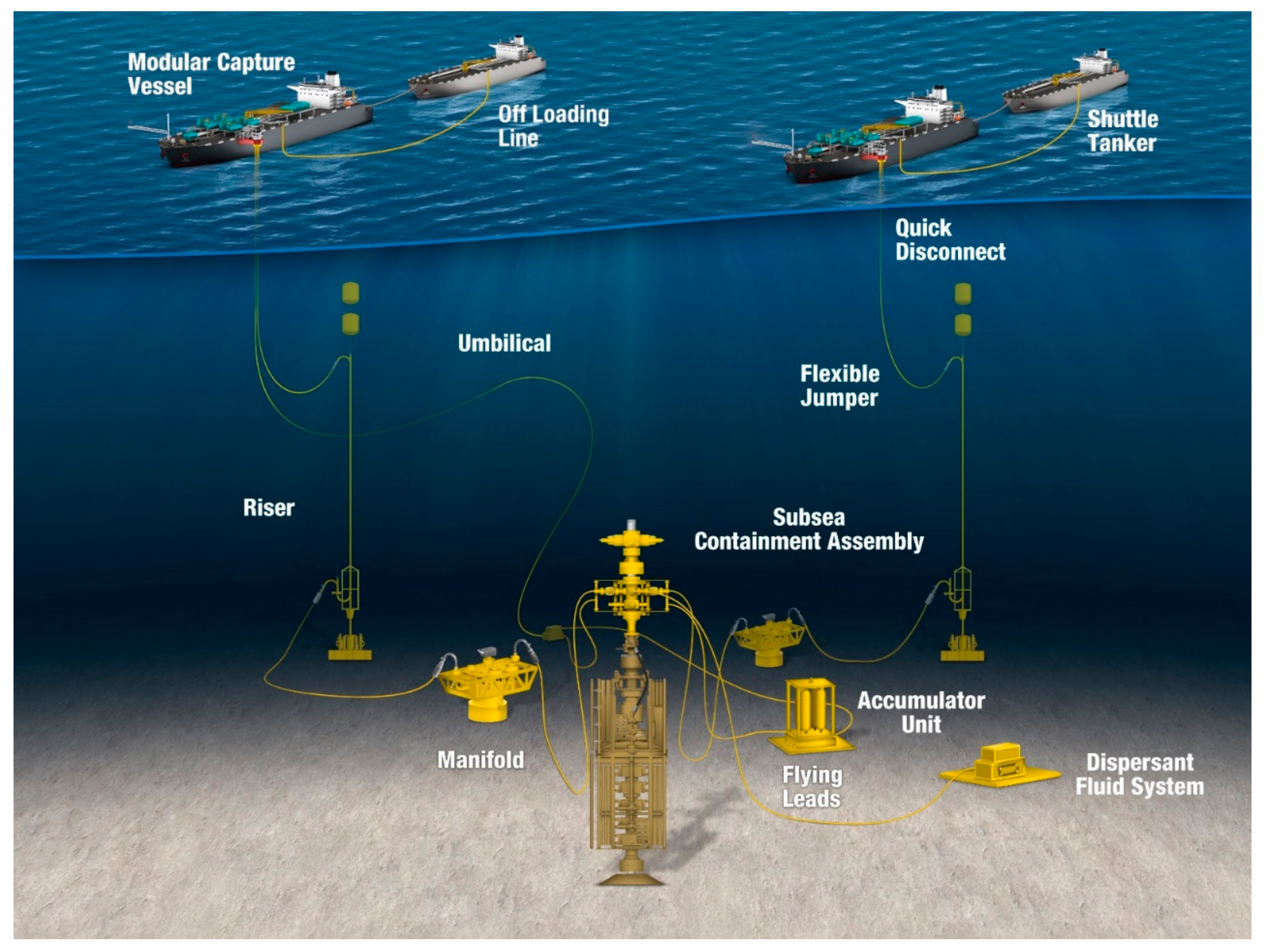
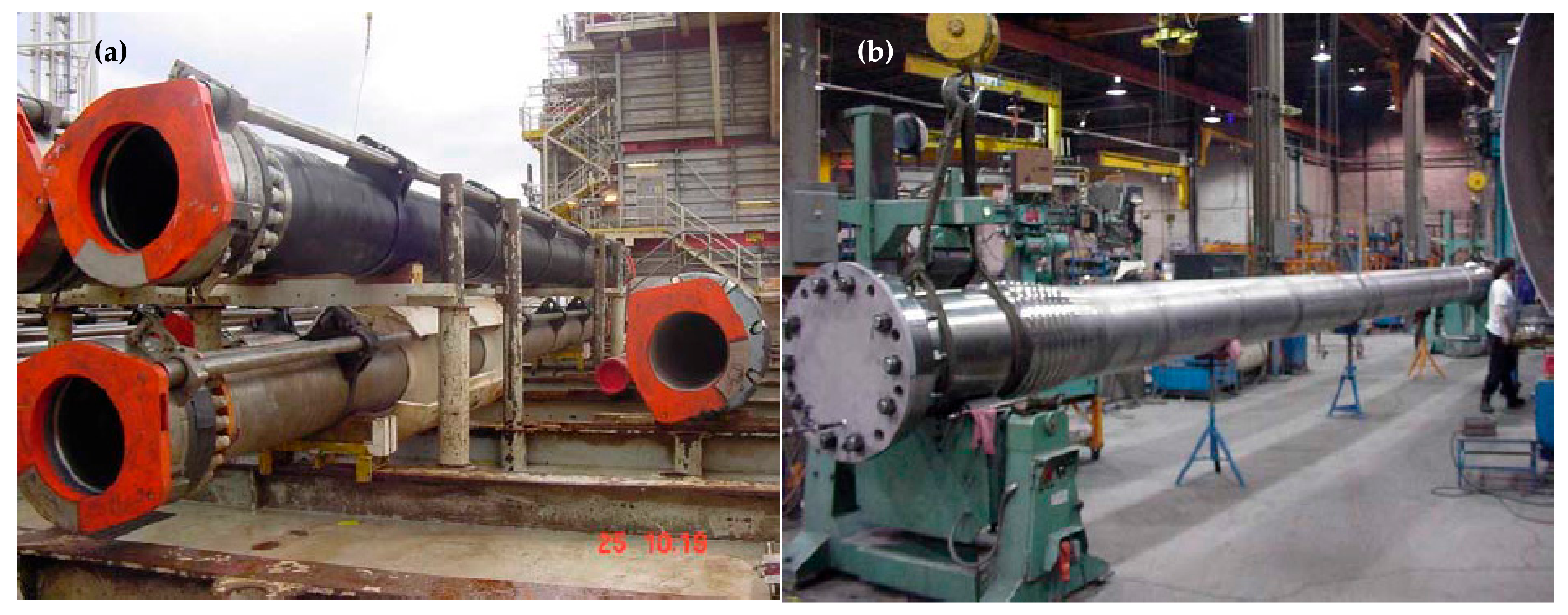
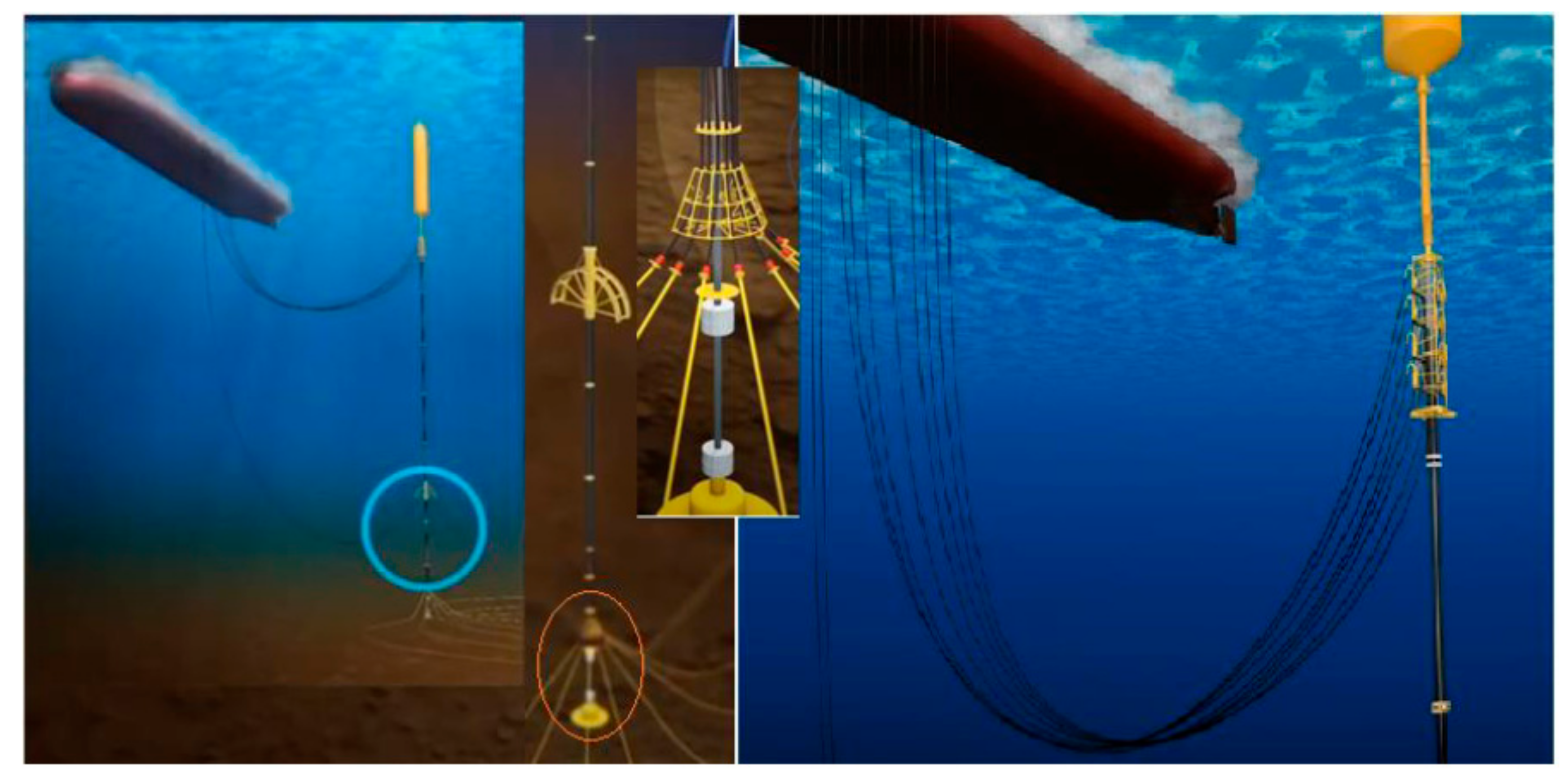
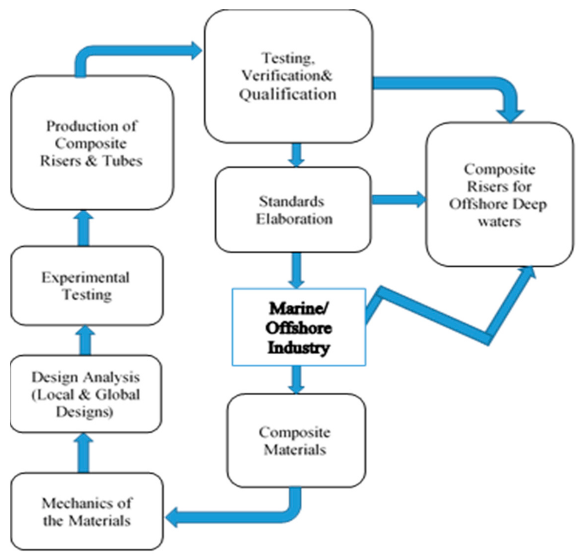
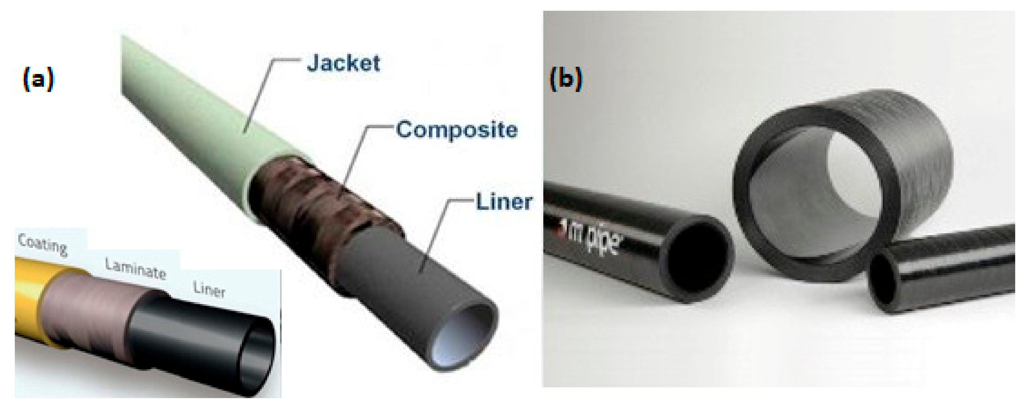
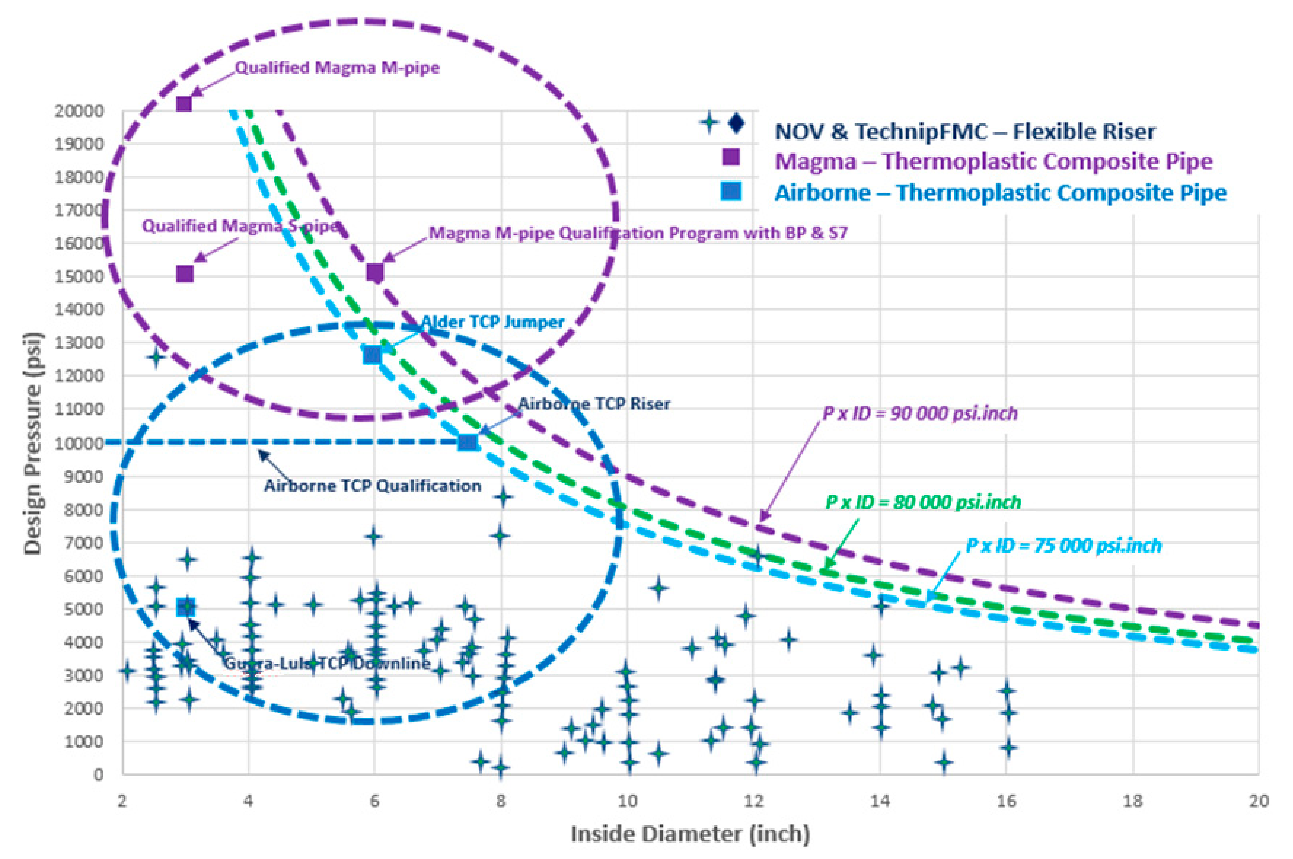
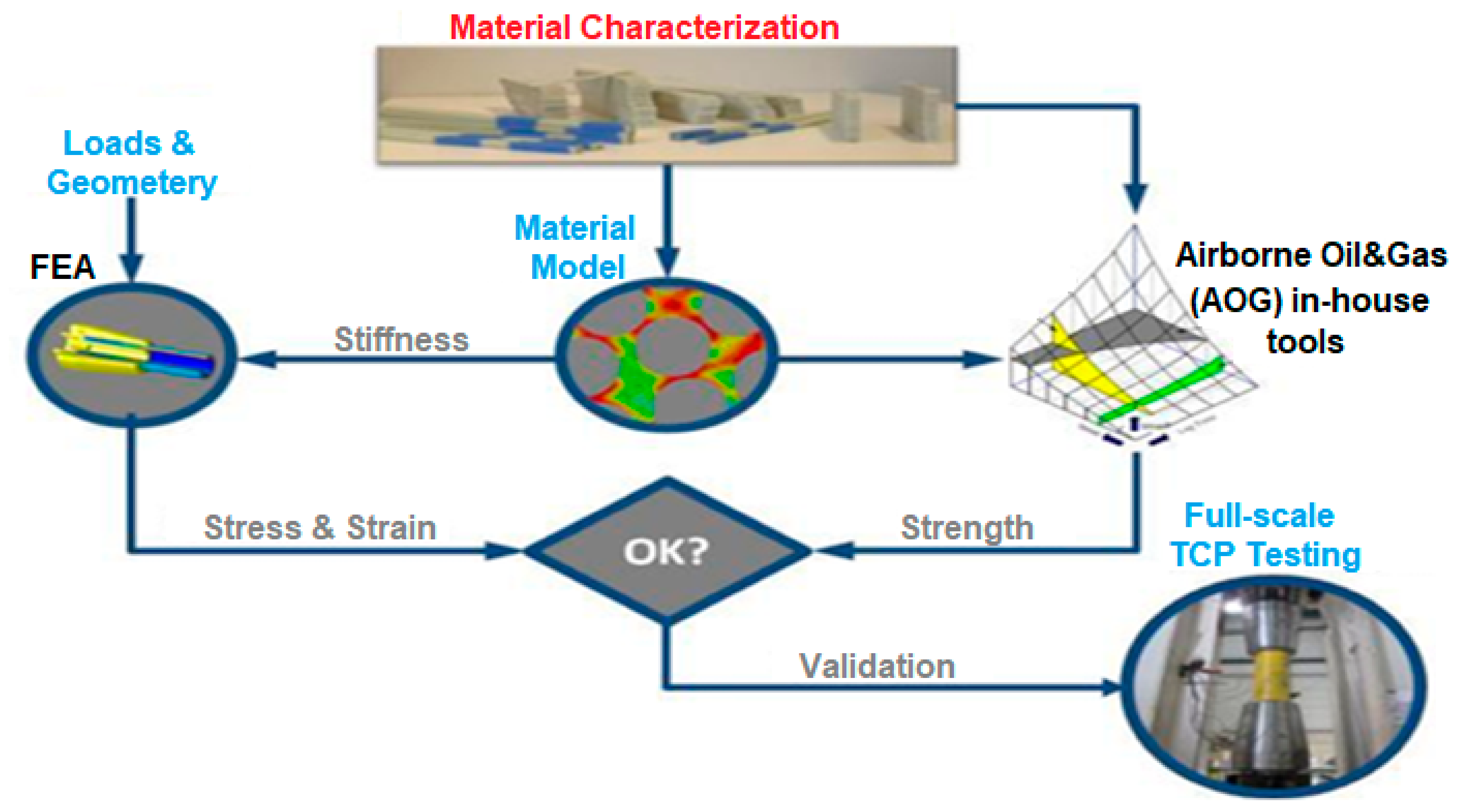
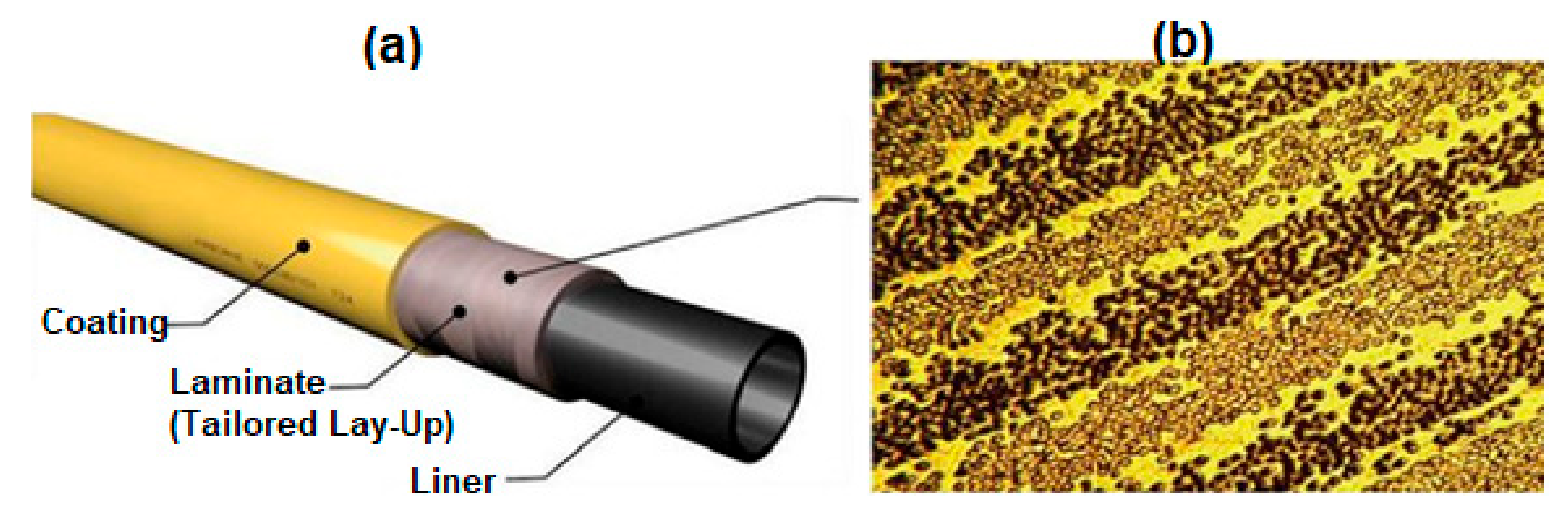
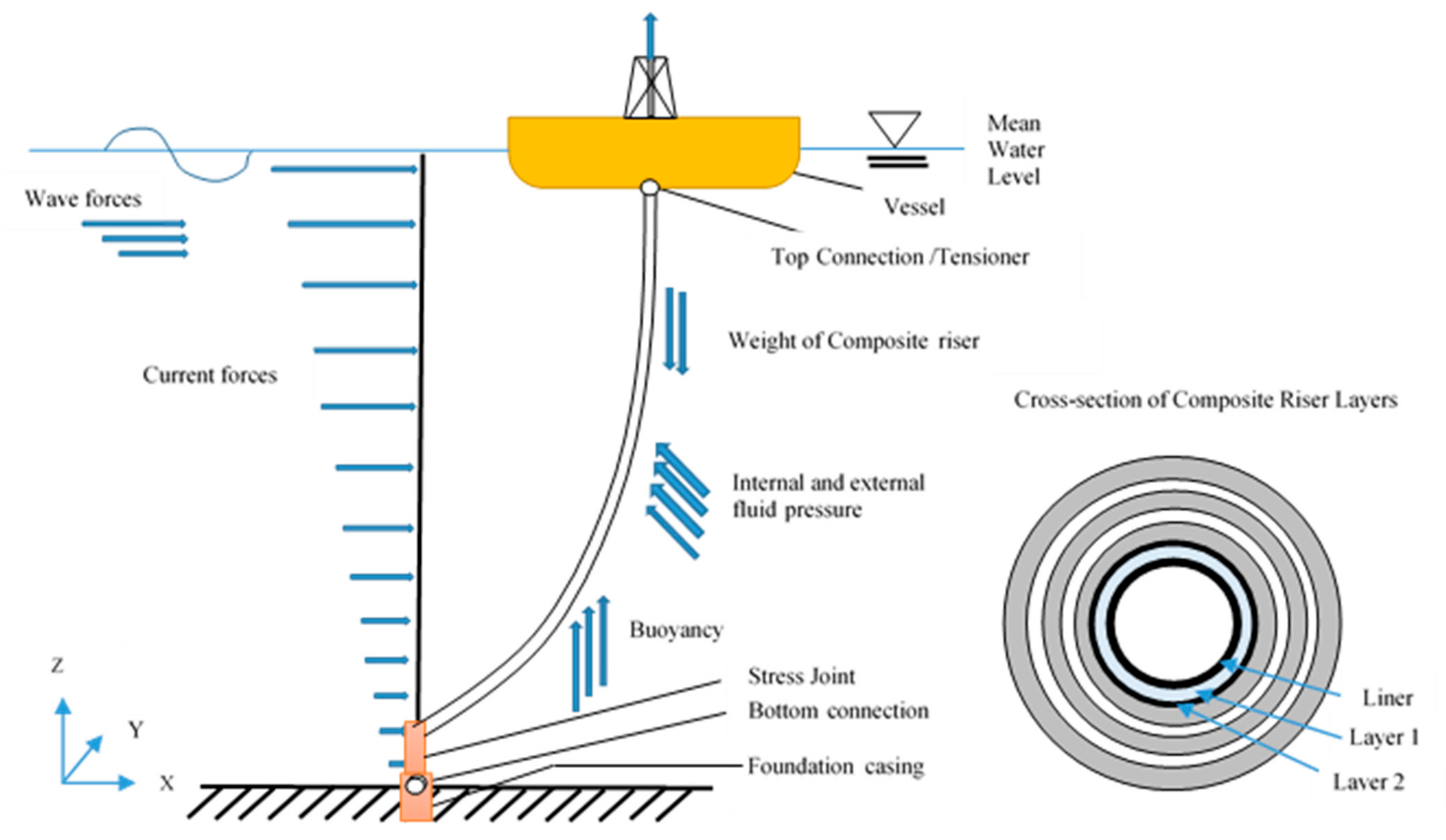
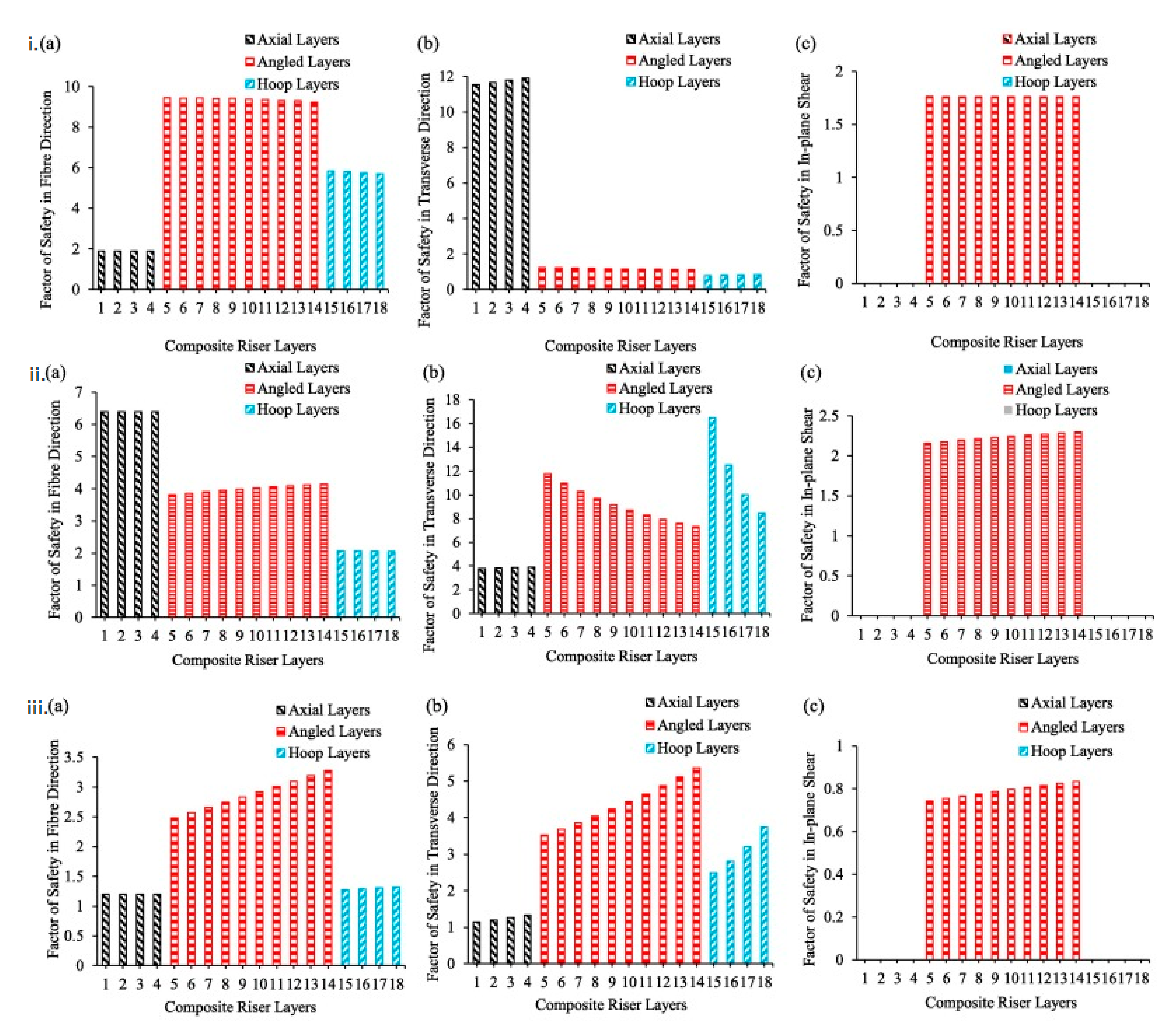
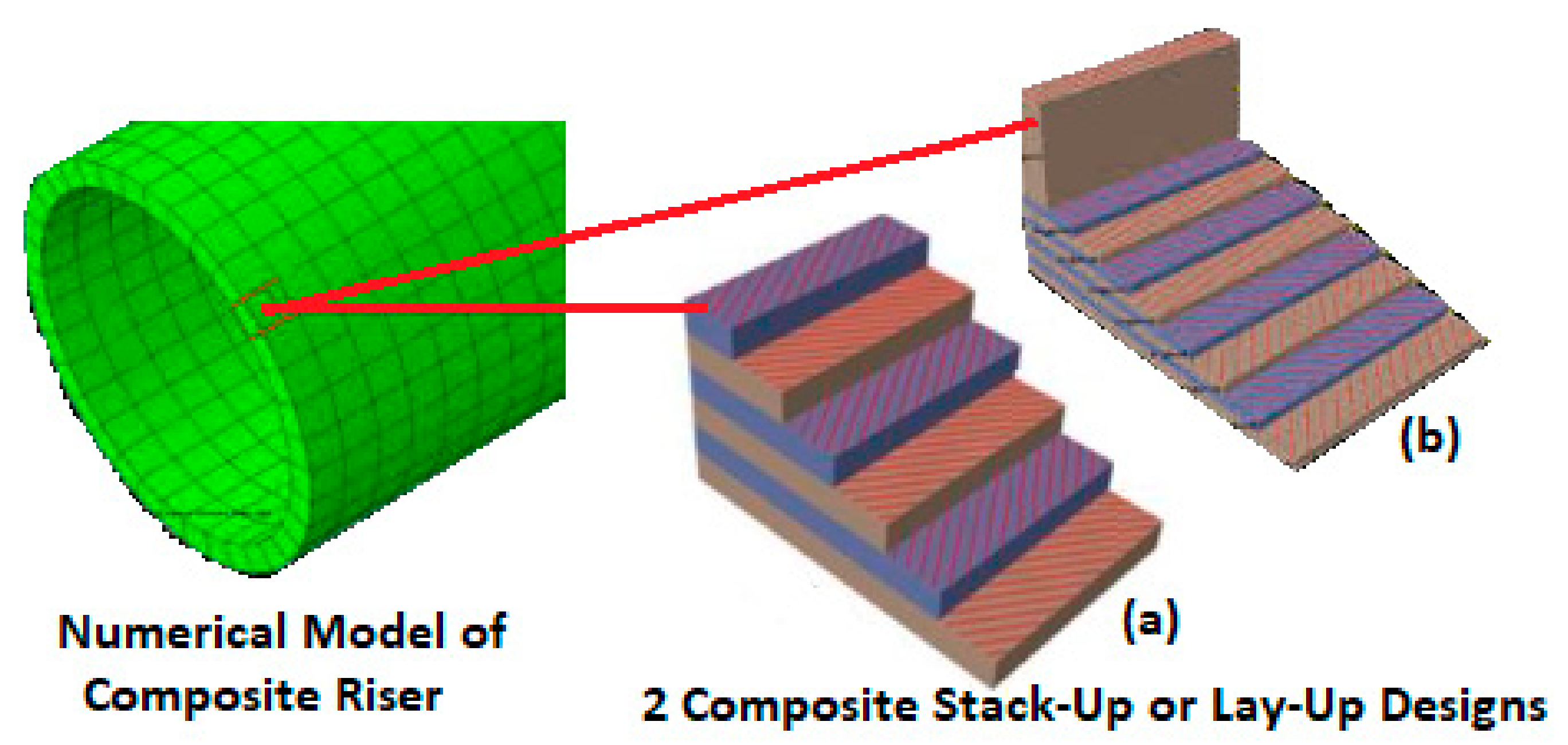
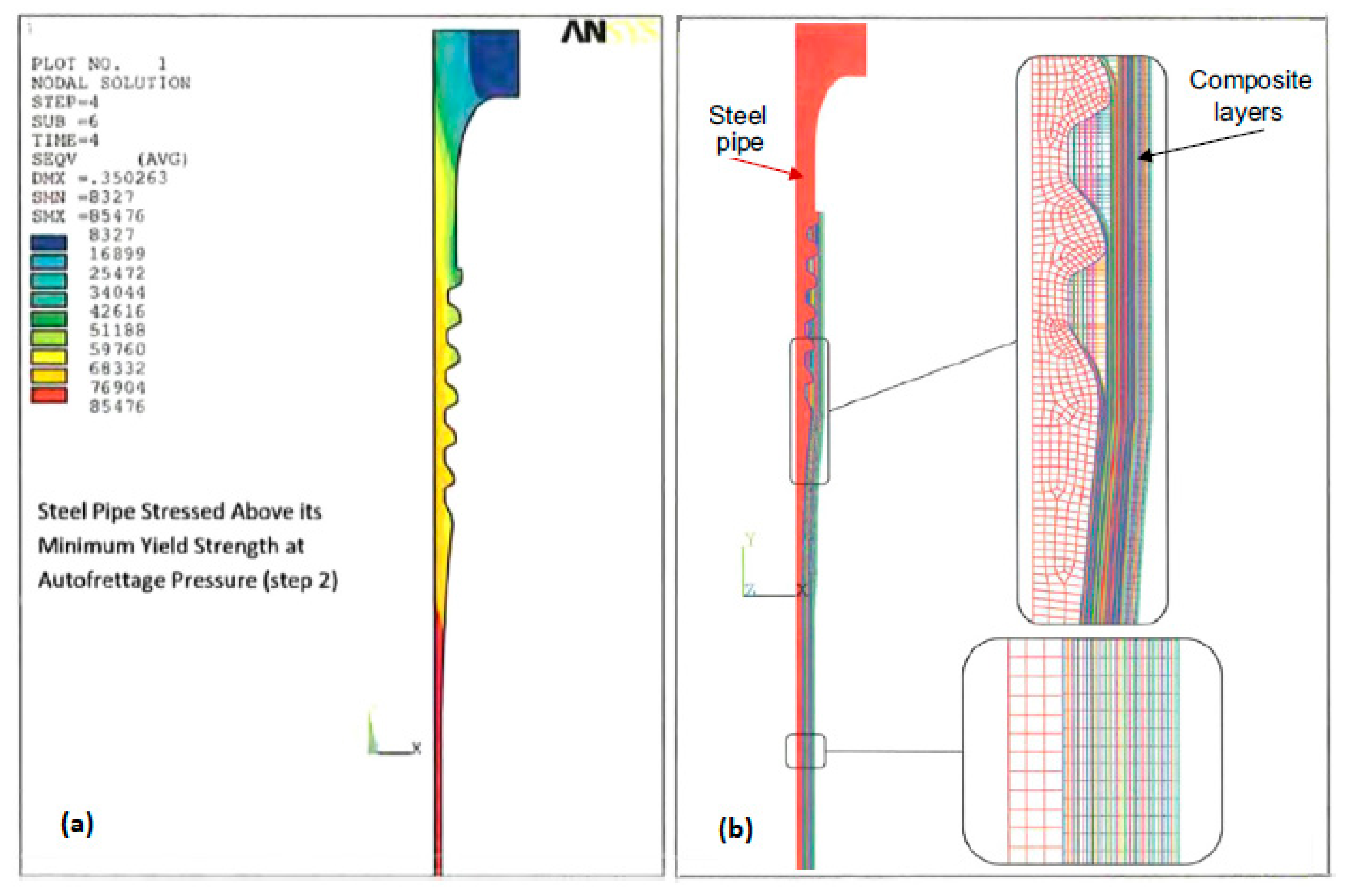
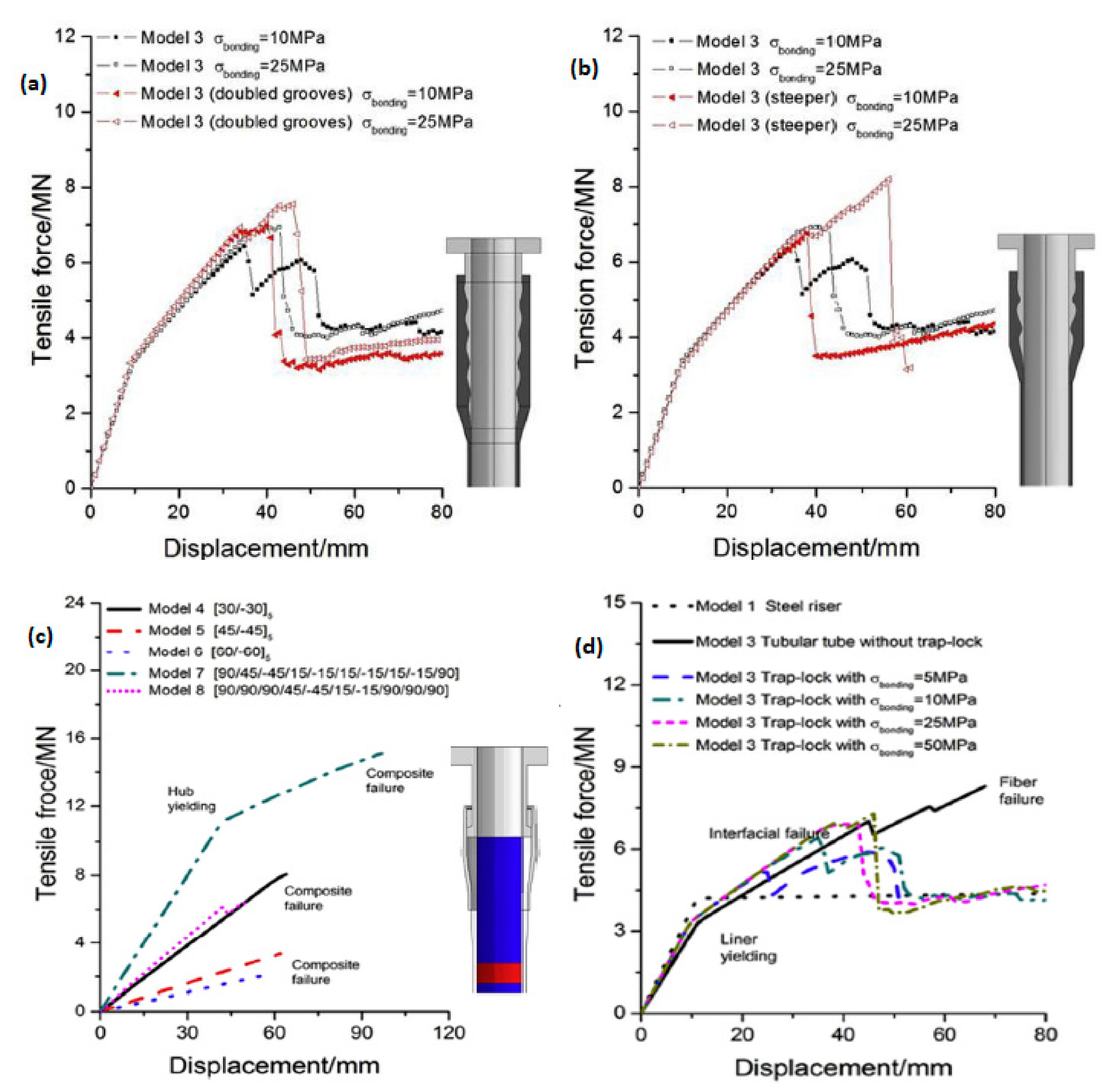
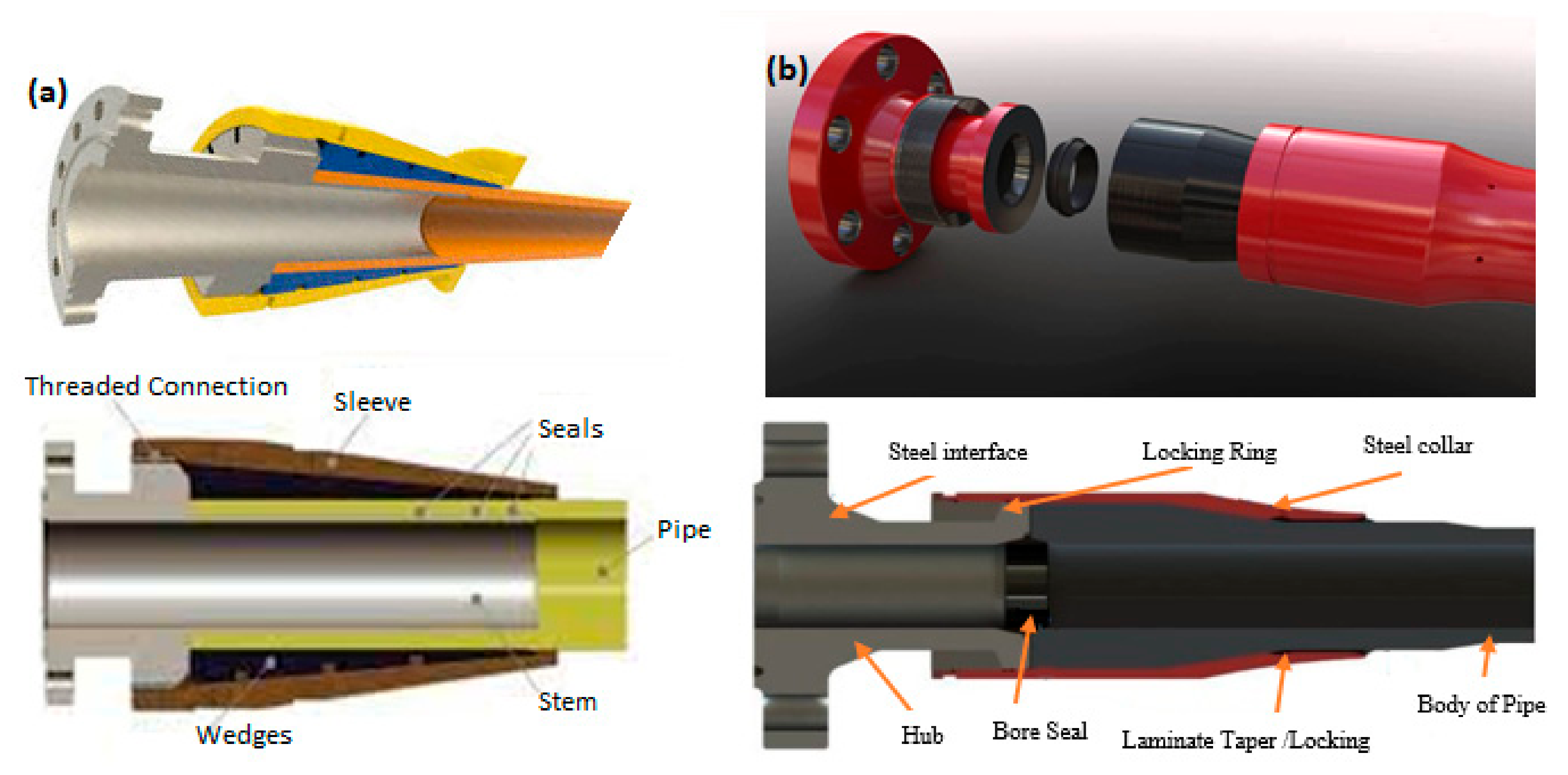
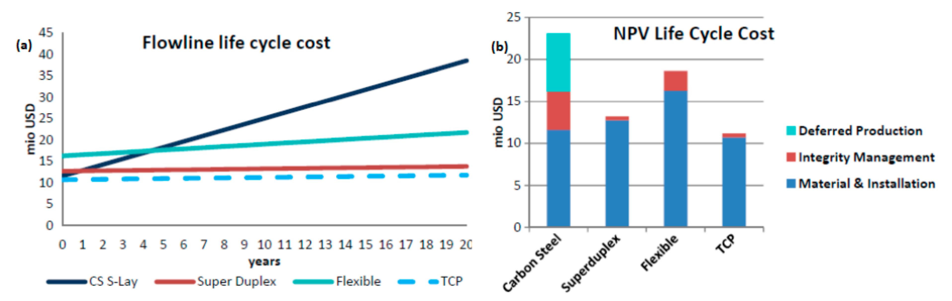
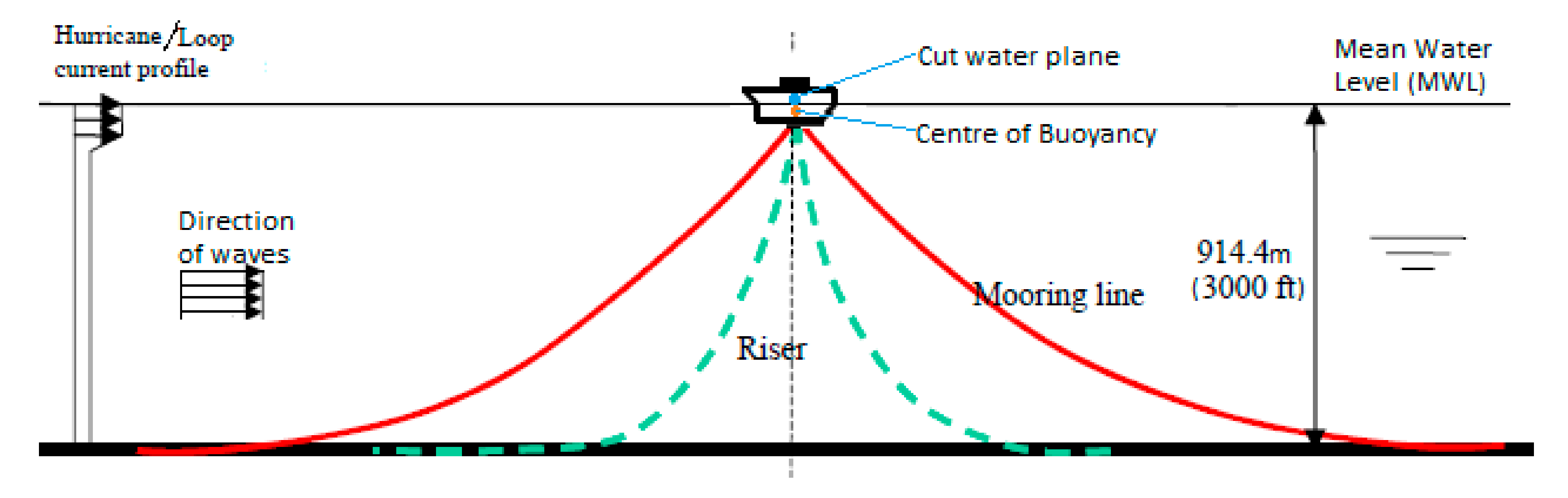
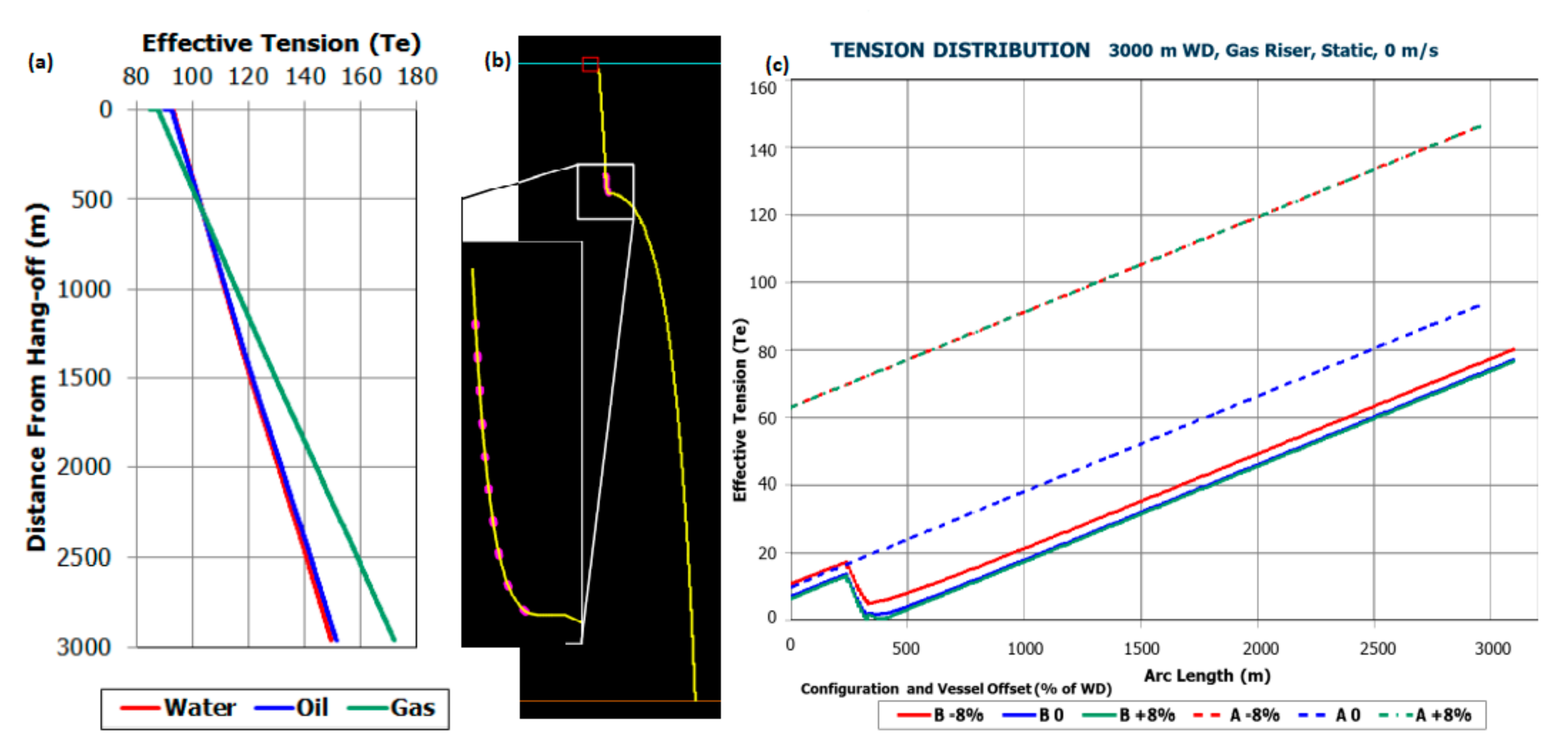
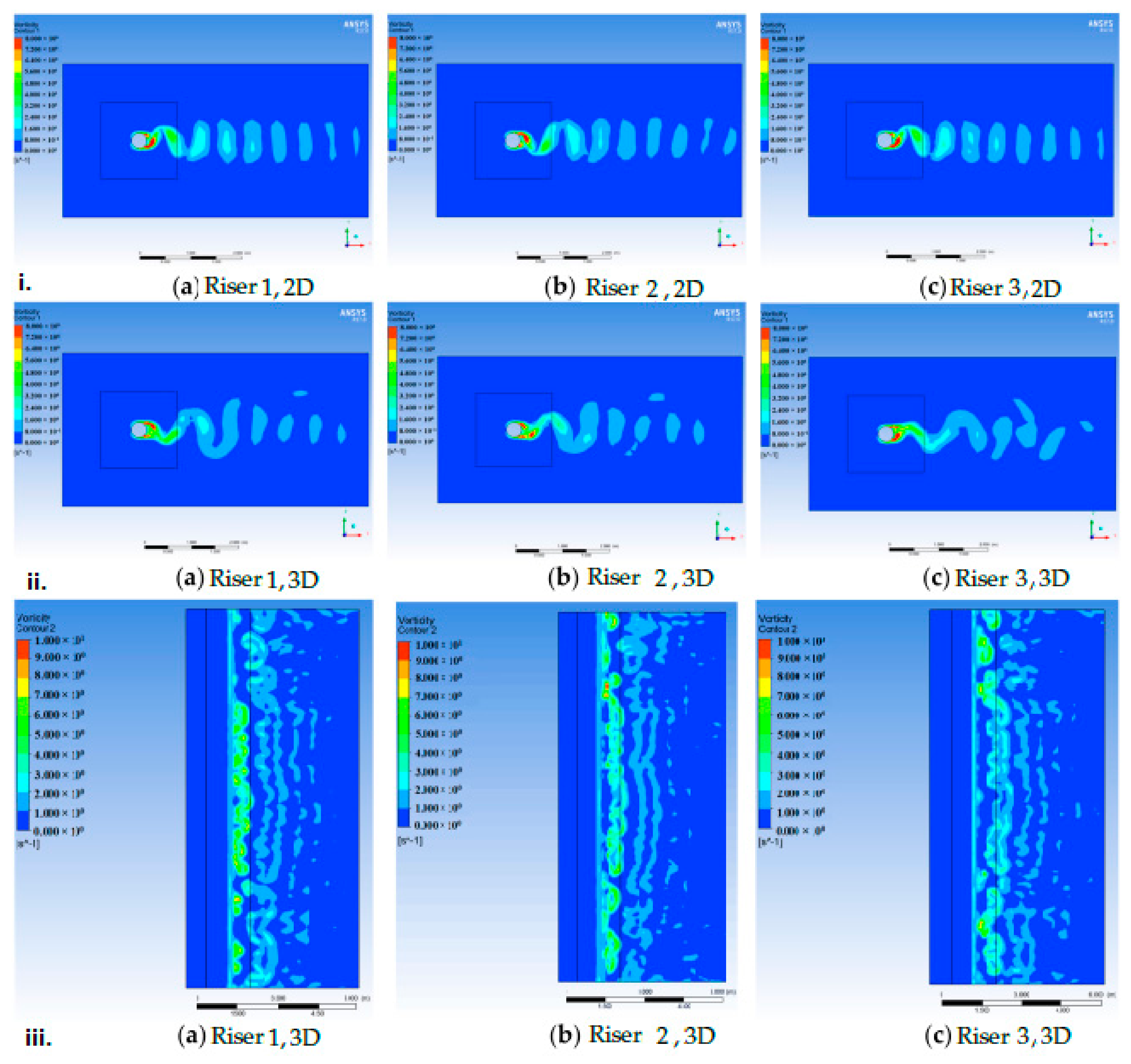
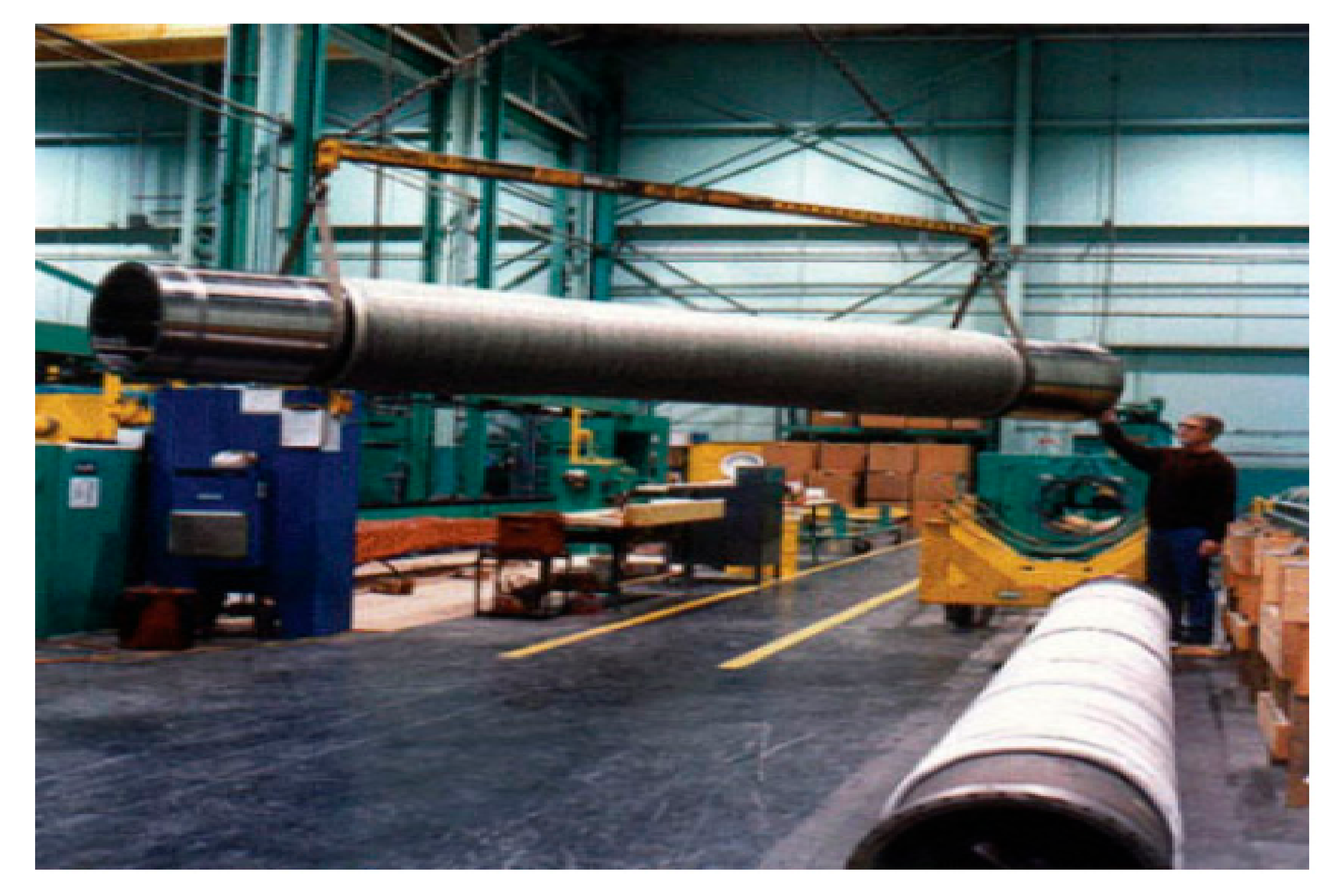
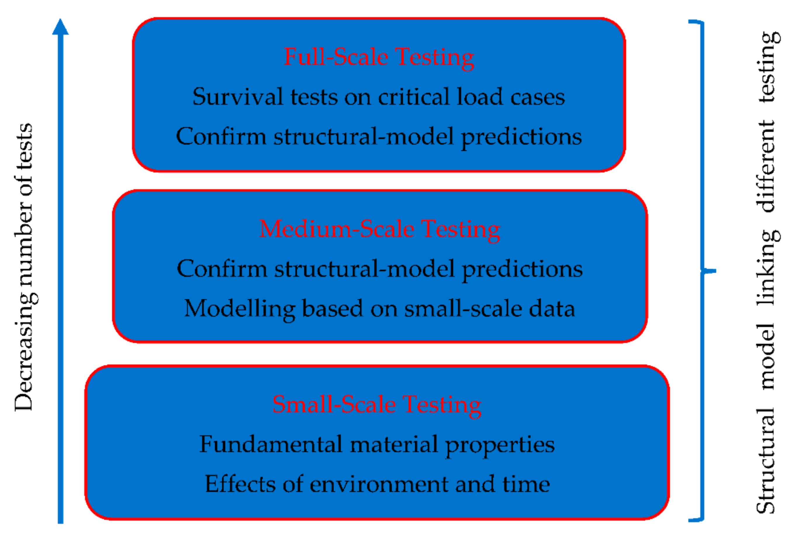
| Year | Project Funder/Country | Reference | Riser Type | Materials | Thickness (mm) | ID (m) | Length (m) |
|---|---|---|---|---|---|---|---|
| 1973 | Ahlstone Marine Riser | [67] | D | Glass fibre/epoxy | -- | -- | -- |
| 1985–1987 | Joint industry program (JIP) by Institut Francais du Petrole and Aerospatiale du France/France | [68,69] | P | Glass and carbon fibres/epoxy | 9.57 (carbon) 7.28 (glass) 1.1 (inner layer) | 0.2286 | 4 and 15 |
| 1994–2000 | National Institute of Standards and Technology (NIST)’s Advanced Technology Program (ATP)/US | [70,71,72,73,74,75,76,77] | D&P | Carbon fibre & E-glass fibers/epoxy | Not specified | 0.496/0.255 | 2.286 |
| 1995–1999 | JIP—ABB, Vetco Gray and University of Houston. | [78,79,80,81] | D | Carbon fibre/epoxy | Not specified | 0.5 | Not specified |
| 1996–2001 | JIP—ABB, Vetco Gray, Aker Kvaerner, Conoco, EU Thermie, Chevron, Hydro, Statoil, Shell and Petrobras/US | [82,83,84,85] | D | Carbon fibre/epoxy | Not specified | 0.5 | Not specified |
| 1999–2000 | JIP-NIST/ATP, Shell & BP-Amoco/US | [86,87] | D&P | Carbon fiber/epoxy | 0.250 | 19 | |
| 1995–2001 | CompRiser JIP—Heidrun CDR joint by Norske Conoco AS and Kvaerner Oilfield Products/Norway | [88,89,90,91,92] | D | Glass and carbon fibre/epoxy | Not specified | 0.536 | 14.585 |
| 2003 | JIP-ConocoPhillips, Kvaerner Oilfield Products & ChevronTexaco/Norway | [93,94] | D&P | carbon fiber/epoxy | Not specified | 0.55 | 14.7 |
| 2007 | Doris Engineering, Freyssinet, Total and Soficar | [95] | P | Carbon fibre/epoxy | -- | -- | -- |
| 2006–2009 | Part of NIST Advanced Technology Program by University of Texas/US | [96,97,98,99,100,101,102,103,104] | D | Glass and carbon fibre/epoxy | 30.5 | 0.540 | 4.57 |
| 2008–2011 | Research Partnership to Secure Energy for America (RPSEA)/US | [105,106,107,108,109,110] | D&P | Glass and carbon fibre plus epoxy | 25.4 (liner) 53.3 (composite) | 0.508 | 10 |
| 2009 | JIP—Airborne Composite Tubulars, MCS Advanced Subsea Engineering & OTM Consulting | [111,112,113,114,115] | D&P | Glass & carbon fiber/epoxy | Not specified | Not specified | Not specified |
| 2011-date | Magma Global of Technip FMC/UK | [116,117,118,119,120,121,122,123,124,125,126] | D&P | Carbon fibre/epoxy | 7–39 | 0.047–0.6 | Up to 27.4 |
| 2011-date | Airborne Oil and Gas (now Strohm)/Netherlands | [127,128,129,130,131,132,133,134,135,136] | D&P | Glass and carbon fibre/epoxy | Varies | Varies | Varies |
| 2011-date | University of New South Wales/Australia | [9,10,11,137,138,139,140,141,142,143,144,145,146,147,148] | P | TCP, carbon fiber/epoxy & PEEK | Varies | Varies | Varies |
| 2015-date | Lancaster University/UK | [12,13,14,15,149,150,151,152,153,154,155] | P | carbon fiber/epoxy & PEEK | Varies | Varies | Varies |
| 2017-date | University of Southampton/UK | [156,157,158,159,160,161,162] | P | carbon fiber/epoxy | Varies | Varies | Varies |
| 2013-date | National University of Singapore/Singapore | [159,160,161,162,163,164,165] | P | carbon fiber/epoxy | Varies | Varies | Varies |
| F-Load or Functional Load | E-Load or Environmental Load | P-Load or Pressure Load | A-Load or Accidental Load |
|---|---|---|---|
| Weight of riser | Floater motions due to currents, waves and wind | Internal fluid pressure (dynamic): global load effects can be generated by both slugs and pressure surges on compliant configurations) | Risk analysis related to support systems, such as loss of mooring line and loss of riser. |
| Weight of the internal fluid | Vessel motions | Internal fluid pressure (static) | A loosened tensioner in the system |
| Applied tensions on top-tensioned risers (TTR) | Waves | Internal fluid pressure (hydrostatic) | Fire hazards, explosions and riser collisions. |
| Installation-induced residual loads or prestressing | Current | External hydrostatic pressure | Flow-induced impact between risers |
| The preloads of connectors | Due to changes in water density, internal waves and other phenomena. | Water levels | Impacts from dropped objects and anchors |
| Guidance loads and applied displacements, plus support for floater’s active positioning system | Dynamic load effects, such as slug flow generated from the fluid pressure (P-Loads) | Naturally occurring environmental issues, such as earthquakes, tsunami, icebergs and hurricanes | |
| Construction loads and loads caused by tools | Icey locations having ice formations or tendency to develop, be slippery or drifts | Failure of lower marine riser package (LMRP) | |
| Soil pressure on buried risers | Seismic effects such as earthquakes (in seismically active regions) | Pressure surge and overpressure of well tubing | |
| Differential settlements | Mean offset including current forces, wind and steady wave drifts | Loss of pressure safety system | |
| Loads from drilling operations | Wave frequency (WF) motion | Seismic effects such as earthquakes (in seismically active regions) | |
| Thermal loads | Low-frequency (LF) motion | Load from anchor, hooks and support systems (hook/snag load) | |
| Inertia | Partial loss of station-keeping capability | ||
| Internally run tools | Internal pressure exceeded | ||
| Buoyancy of riser (including absorbed water), attachments, fluid contents, anodes, marine growths, buoyancy modules, tubing and coatings. | Risk analysis related to monitoring failure, such as dynamic positioning system (DPS), loss of buoyancy and loss of heave compensating system |
| Type of Model | Problems to Be Solved | Loads to Check for |
|---|---|---|
| Composite risers | Global analysis and local analyses | Load distribution on riser ends |
| Compound infinite anisotropic cylinder | Stress and strength analysis, selection of layer thicknesses and technological parameters | Dead weight, internal pressure, external pressure, residual stresses from force winding and thermal shrinkages |
| Compound semi-infinite cylinder | Stress concentration and length of boundary effect zone | Load distribution effect on riser ends |
| Cylindrical sections of different lay-ups on axial coordinate | Selection of reinforcement scheme at different depths of sections | Load variation along axial coordinate |
| Cylindrical section with lay-up varying in wall thickness | Optimisation of reinforcement scheme of riser sections | Nonuniformity of stress fields on wall thickness |
| Extensible weighted thread | Estimation of axial strength, effect of extensibility of riser axis on its deflection | Dead weight and flow-past |
| Flexible rod in linear statement | Calculation of riser deflection and stresses | Flow-past, reactive forces and moments |
| Flexible rod in nonlinear statement | Stresses, deflection, required top tension at longitudinal-transverse bending and buckling | Dead weight, flow-past, top end tension, reactive forces and moments |
| Laminated cylindrical tube | Displacements and stresses | Bending loads, torsion, tensile loads, external pressure, and internal pressure. |
| Multilayered cylindrical shell | Stress, strain and strength analysis | Effect of asymmetric loading (flow-past, concentrated loads) |
| Repaired cracks in composite pipes | Fracture using stress intensity factor (SIF) | Load distribution |
| Quasilinear 3D anisotropic elastic cylinder | Refined calculation of stresses | Synergetic effect of different loads |
| Property | Specific Gravity | Young’s Modulus (GPa) | Poisson Ratio, v | Density (kg/m3) |
|---|---|---|---|---|
| Composite Riser | 1.68 | (depends) | 0.28 | 1680 |
| Steel | 7.8 | 200 | 0.30 | 7850 |
| Titanium | 4.43 | 113.8 | 0.342 | 4430 |
| Aluminium | 2.78 | 68.9 | 0.33 | 2780 |
| PEEK | 1.32 | 5.15 | 0.40 | 1300 |
| P75/PEEK | 1.77 | 33 | 0.30 | 1773 |
| P75/Epoxy | 1.78 | 31 | 0.29 | 1776 |
| Sea Water | 1.0 | 2.15 | 0.5 | 1030 |
| AS4-PEEK | 1.56 | 66 | 0.28 | 1561 |
| AS4-Epoxy | 1.53 | 49 | 0.32 | 1530 |
| Authors | Title | Highlight |
|---|---|---|
| Gibson A.G. [306] | Composites for Offshore Applications | Compared steel, protruded FRP against steel and wood |
| Hopkins P. et al. [196] | Composite Pipe Set to Enable Riser Technology in Deeper Water | Compared both steel and composite riser performances and riser fatigue |
| Cheldi T. et al. [4] | Use of spoolable reinforced TCP pipes for oil and water transportation | Spoolable reinforced TCP pipes, material design |
| Toh W. et al. [187] | A comprehensive study on composite risers: Material solution, local end fitting design and global response | End-fitting design for composite risers and global design with VIV responses |
| Hopkins P. et al. [197] | Composite riser study confirms weight, fatigue benefits compared with steel | Compared the composite risers and steel riser with material attributes |
| OGJ [211] | Composite riser technology advances to field applications | Compared the composite risers and steel riser with material attributes |
| Pham D.C. et al. [160] | A review on design, manufacture and mechanics of composite risers | Comparative assessment of the literature |
| Amaechi C.V. et al. [149] | Composite Risers for Deep Waters Using a Numerical Modelling Approach | Numerically compared composite riser models, compared different liners |
| Ward E.G. et al. [101] | A Comparative Risk Analysis of Composite and Steel Production Risers | Comparison assessment, local design, global riser analysis and risk analysis for both steel and composite risers. |
| Pham D.C. et al. [159] | Composite riser design and development—a review | Comparative assessment of the literature |
| Saleh P. [199] | The benefits if composite materials in deepwater riser applications | Benefits of composites in developing composite risers |
| Brown T. [246] | The impact of composites on future deepwater riser configurations | Configurations for composite risers, with fatigue of steel and composite risers |
| Lamacchia D. [217], Lamacchia D. et al. [276], | Thermoplastic Composite Pipe (TCP) Offshore Market 101 | Compared MagmaGlobal and Airborne Oil&Gas TCP pipes for composite risers |
| Saad et al. [55] | Application of composites to deepwater top tensioned riser systems | Economic aspects of composite risers on SPAR and TLP |
| Mintzas A. et al. [134] | An integrated approach to the design of high performance carbon fibre reinforced risers—from micro to macro scale | Combined bend–burst, burst and compressive tests |
| Amaechi et al. [153] | Local and Global Design of Composite Risers on Truss SPAR Platform in Deep waters | Comparative assessment of composite risers; local and global design |
| Wang et al. [141] | Tailored design of top-tensioned composite risers for deep-water applications using three different approaches | Numerically compared composite riser models, compared 3 different approaches |
| Gibson A.G. [80] | The cost effective use of fiber reinforced composites offshore | Compared the composite risers and steel riser with material attributes |
| Andersen W.F. et al. [71] | Full-Scale Testing of Prototype Composite Drilling Riser Joints-Interim Report | Full-scale testing on composite riser |
| Wang et al. [142] | Global design and analysis of deep sea FRP composite risers under combined environmental loads | Numerically compared composite riser models, global and local design |
| Kim W.K. [98] | Composite production riser assessment | Compared steel and composite risers, local and global design, |
| Gibson A.G. et al. [82] | Non-metallic pipe systems for use in oil and gas. | Application of composite pipes |
| Reference | Highlights and Test Modes | Specimen Type | Program/Test Scale |
|---|---|---|---|
| Sparks et al. [68] | Attributes of composite risers on concrete TLP, collapse pressure test, fatigue test | Composite riser | Full-scale and small-scale |
| Andersen et al. [71] | Burst, and tension tests | Composite drilling riser joint | Full-scale |
| Gibson [81] | Flexure, tension, fire, durability, blast, impact test, axisymmetric burst, marine composite application, fatigue test | Fibre-reinforced composite pipes and coupons | Full-scale and Small-scale |
| Picard D. et al. [95] | Tensile test, manufacture of TCP pipe | Composite tube | Large-scale |
| Ramirez and Engelhardt [96,97] | Collapse pressure test, buckling | Composite tube | Full-scale |
| Alexander et al. [105] | Burst, bending cycles, impact/drop tests | Composite tube | Full-scale |
| Cederberg et al. [109,110] | Burst, collapse and impact tests | Composite drilling riser | Full-scale |
| Mintzas et al. [134] | Tensile test, micro-scale test | Carbon fibre repaired riser | Small-scale |
| Chen et al. [186] | Burst, and tension tests | Composite riser end fitting | Small-scale |
| Pham et al. [161] | Bending under transverse loads | Composite pipe and coupons | Full-scale |
| Sobrinho et al. [224] | Thermal and Mechanical tests | ||
| Ye et al. [257,258] | Tensile test, SEM and CT tests | Glass fibre composite/epoxy | Small-scale |
| Ellyin et al. [262] | Flexure test, tension test | Composite pipes and coupons | Small-scale |
| Grant and Bradley [280] | Flexure test, tension test | Composite pipes and coupons | Small-scale |
| Huang et al. [307,308] | Tensile and fatigue tests | Carbon fibre composite pipe and coupons | Large-scale |
| Alexander and Ochoa [327] | Burst, tension and 4-point bend tests | Carbon fibre composite repaired steel riser | Full-scale |
| Rodriguez and Ochoa [328] | 4-point flexural test, fatigue test | Carbon and glass fibres/epoxy | Small-scale |
| Lindsey and Masudi [328,329] | Cyclic test, tension in sea water cases from 25 °C to 75 °C | Graphite epoxy composite | Small-scale |
| Soden et al. [330] | Flexure test, tension test | Composite pipes and coupons | Small-scale |
| Reference | Numerical Methods | Highlights |
|---|---|---|
| Bai et al. [248,299] | Numerical model, von Mises failure criteria | TCP Pipe, internal pressure ABAQUS |
| Andersen [8] | Minimum potential energy approach; failure criteria; progressive damage | Analysis of transverse cracks in composites |
| Rodriguez and Ochoa [328] | Numerical and experimental, spoolable tube bending; material failure mode; 2D shell element | Flexural response of spoolable composite tubular |
| Toh et al. [187] | Tensile strength assessment, mode shape from global response | Analysis of 2 composite riser end-fittings—taplock and Magma |
| Chen et al. [186] | Tensile strength, prototype design and analysis; composite riser joints | Numerical and test analysis of composite riser end-fitting; mechanical tests, tension and combined tension-bending loading tests of composite riser joints |
| Amaechi et al. [149,150,151] | Novel numerical approach in ANSYS ACP to model composite riser; netting theory; for 18 layers of composite riser | Buckling, burst, collapse, tension; under 6 load conditions, presented stress profiles for F.S of different layers in 3 stress directions, presented buckling modes |
| Jamal and Karyadi [213] | Collapse test; under pure bending; LR-739 composite cylindrical tube | Material failure using Novozhilov’s nonlinear thin-shell theory |
| Corona et al. [233] | Nonlinear analysis using material failure criteria and constitutive modelling | Bending response of long and thin-walled cross-ply composite cylinders |
| Wang C. et al. [137,138,139,140,141,142] | Design of composite risers for minimum weight; Numerical method using ANSYS APDL to model composite riser. | Local design and global design of composite riser; design on min. weight, factor of safety results in 3 stress directions; Under combined loadings and global responses |
| Elhajjar R. et al. [322] | A hybrid numerical and imaging approach for characterizing defects in composite structures | Structural and elastic failure responses of composites; hybrid approach coupling with a progressive FEA |
| Tatting, B. F. et al. [228] | The Brazier effect for finite-length composite cylinders under bending | Numerical nonlinear analysis using semi-membrane constitutive theory for the analyses. |
| Brazier L.G. [325] | Analysed the flexural behaviour of thin cylindrical shells and other thin sections | The flexural behaviour of thin cylindrical shells and nonlinear bending analysis |
| Reference | Highlights and Test Modes | Method Used | Specimen Type | Program/Test Scale |
|---|---|---|---|---|
| Thomas (2004) | Fatigue test | S-N approach | Composite riser | Full-scale |
| Huybrechts [302] | Fatigue test, fatigue life estimation | S-N approach | Composite tube | Full-scale |
| Salama et al. [89,90,91] | Fatigue test | S-N approach | Composite riser | Full-scale |
| Chouchaoui and Ochoa [225,226] | Fatigue test | S-N approach | Composite coupons | Small-scale |
| Sobrinho et al. [223] | Application-based test | S-N approach | Composite coupons | Small-scale |
| Mertiny et al. (2004) | Fatigue test | S-N approach | Composite coupons | Small-scale |
| Cederberg [109] | Fatigue test, fatigue life estimation | Strain-life model | Composite riser and steel-reinforced drilling riser | Large-scale |
| Kim [98] | Fatigue life estimation | Semi-log S-N approach, Power law S-N approach | Composite riser tube | Large-scale |
| Echtermeyer et al. (2002) | Fatigue life estimation | S-N approach | Composite tube | Small-scale |
| Liu K. et al. [291] | Fatigue life estimation | S-N approach | Composite tube | --- |
| Yu K. et al. [148] | Fatigue life estimation | S-N approach | Composite tube | --- |
| Sun S.X. et al. [163] | Fatigue life estimation | S-N approach | Composite tube | --- |
| Type of Test | Prediction Result | Measured Result | Failure Location |
|---|---|---|---|
| Burst pressure test with closed end loads | 14,800 psi | 15,850 psi | Body failure |
| Impact with 5000 kg m (36,170 ft-lb) dropped casing | No structural damage | No structural damage | No failure |
| Cyclic bending stress range of 850 kN m (627,000 lb-ft), cycles | 140,000 psi | 160,000 psi -180,000 psi | Circ weld in the Titanium (Ti) liner |
| Particulars | Steel | Composite | Observations |
|---|---|---|---|
| Max Hang-Off Load (te) | 94 | 93 | In an SLHR, the flexible jumper to the vessel acts as interface between the vessel and the vertical riser leg, thus keeping the two isolated. Therefore, negligible change in hang-off loads was seen |
| Max Hang-Off Bending Moment (kNm) | 261 | 282 | |
| Max Stress Utilisation | 0.63 | --- | While stress is the driving criterion for steel, strain is the driving criterion for composites |
| Max Safety Factor | --- | 2.76 | MBR is larger than minimum acceptable value |
| Max Tension Utilisation | --- | 0.14 | Tension is low in comparison to the allowable tension |
| Max Buoyancy Tank Displacement (m) | 247 | 211 | Smaller drag area causes smaller buoyancy tank displacement |
| Max Buoyancy Tank Tension (Te) | 451 | 258 | 43% less tension required |
| Max Bending Moment at Base of URA (kNm) | 116 | 62 | Approximately 50% lower bending moment from URA and LRA. |
| Max Bending Moment at Top of LRA (kNm) | 581 | 270 |
| Particulars | Values | Observations |
|---|---|---|
| Pipe ID | 8 in | This is the maximum recommended, and is driven by the collapse criteria |
| Pipe Max OD | 11.9 in | The wall thickness can vary, and thus a smaller pipe OD can be used at shallower depths |
| Tension at Top | 257 Te | Similar level to composite at 2000 m water depth. Note pipe size is different |
| MBR Safety Factor | 2.84 | Acceptable MBR |
| Max Tension Utilisation | 0.17 | Very low utilisation |
| Bending Moment At top of LRA | 237.70 | Similar to composite pipe at 2000 m |
| Bending Moment At base of URA | 32.20 | Similar to composite pipe at 2000 m |
| Maximum Flexible Joint Rotation | 8.1 Degrees | Slight increase in comparison to 2000 m |
Publisher’s Note: MDPI stays neutral with regard to jurisdictional claims in published maps and institutional affiliations. |
© 2022 by the authors. Licensee MDPI, Basel, Switzerland. This article is an open access article distributed under the terms and conditions of the Creative Commons Attribution (CC BY) license (https://creativecommons.org/licenses/by/4.0/).
Share and Cite
Amaechi, C.V.; Chesterton, C.; Butler, H.O.; Gillet, N.; Wang, C.; Ja’e, I.A.; Reda, A.; Odijie, A.C. Review of Composite Marine Risers for Deep-Water Applications: Design, Development and Mechanics. J. Compos. Sci. 2022, 6, 96. https://doi.org/10.3390/jcs6030096
Amaechi CV, Chesterton C, Butler HO, Gillet N, Wang C, Ja’e IA, Reda A, Odijie AC. Review of Composite Marine Risers for Deep-Water Applications: Design, Development and Mechanics. Journal of Composites Science. 2022; 6(3):96. https://doi.org/10.3390/jcs6030096
Chicago/Turabian StyleAmaechi, Chiemela Victor, Cole Chesterton, Harrison Obed Butler, Nathaniel Gillet, Chunguang Wang, Idris Ahmed Ja’e, Ahmed Reda, and Agbomerie Charles Odijie. 2022. "Review of Composite Marine Risers for Deep-Water Applications: Design, Development and Mechanics" Journal of Composites Science 6, no. 3: 96. https://doi.org/10.3390/jcs6030096