
Mechanically Stable β-TCP Structural Hybrid Scaffolds for Potential Bone Replacement

 , ,
, ,  , , ,
, , ,
Abstract
:1. Introduction
2. Materials and Methods
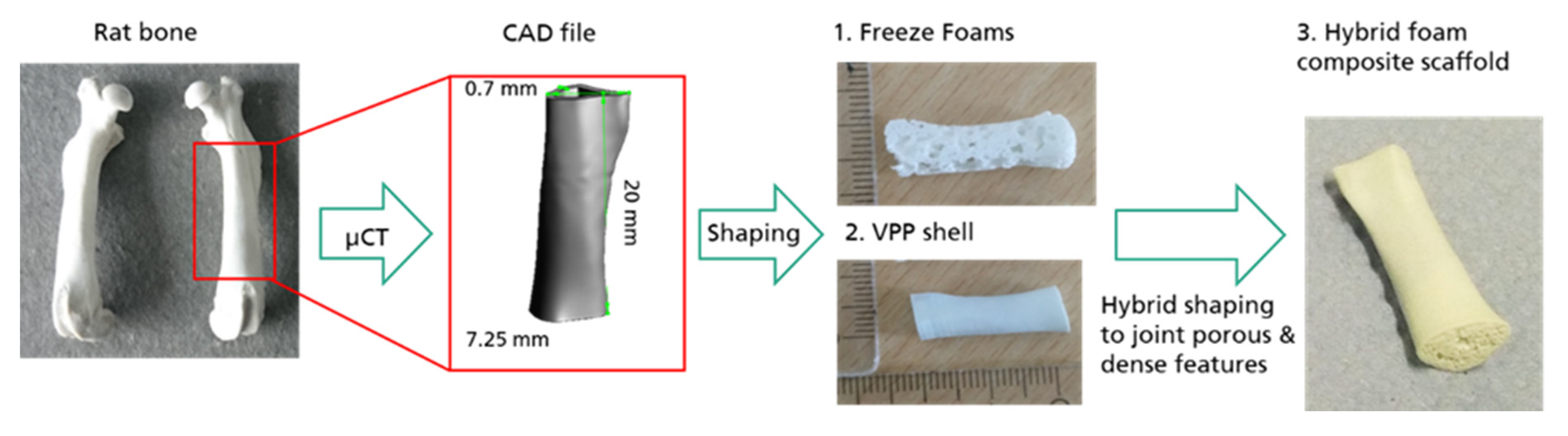
2.1. Freeze Foaming
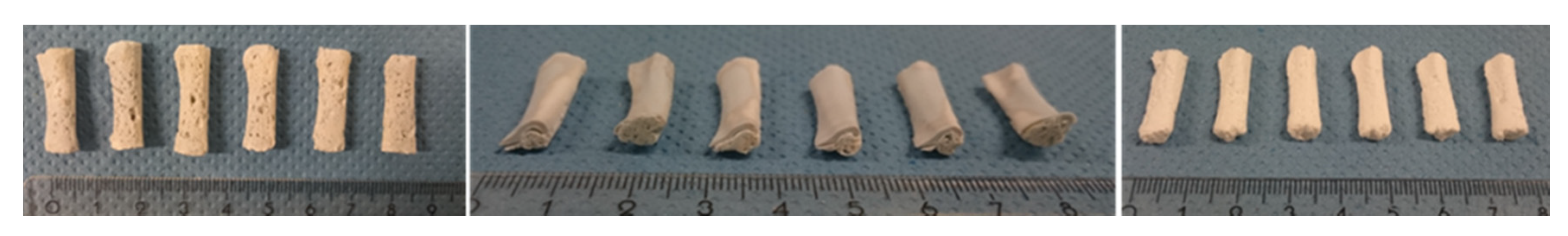
Freeze Foaming for In Vivo Studies
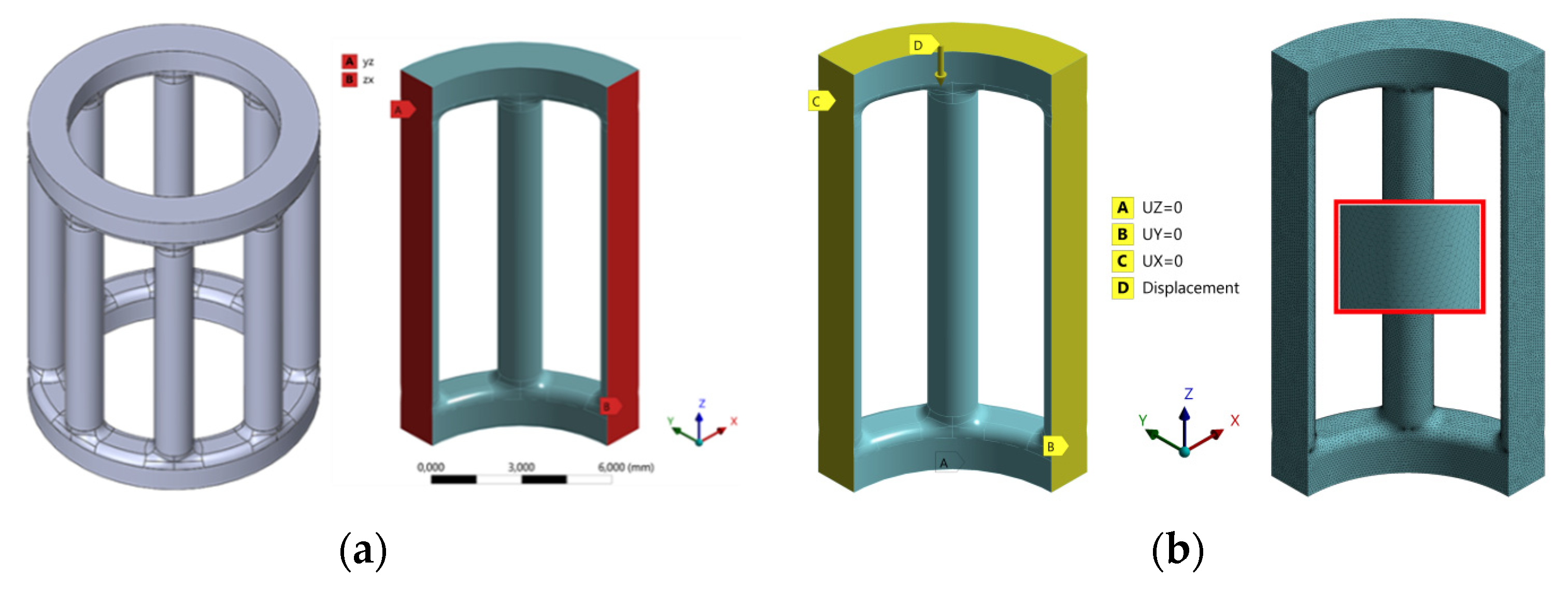
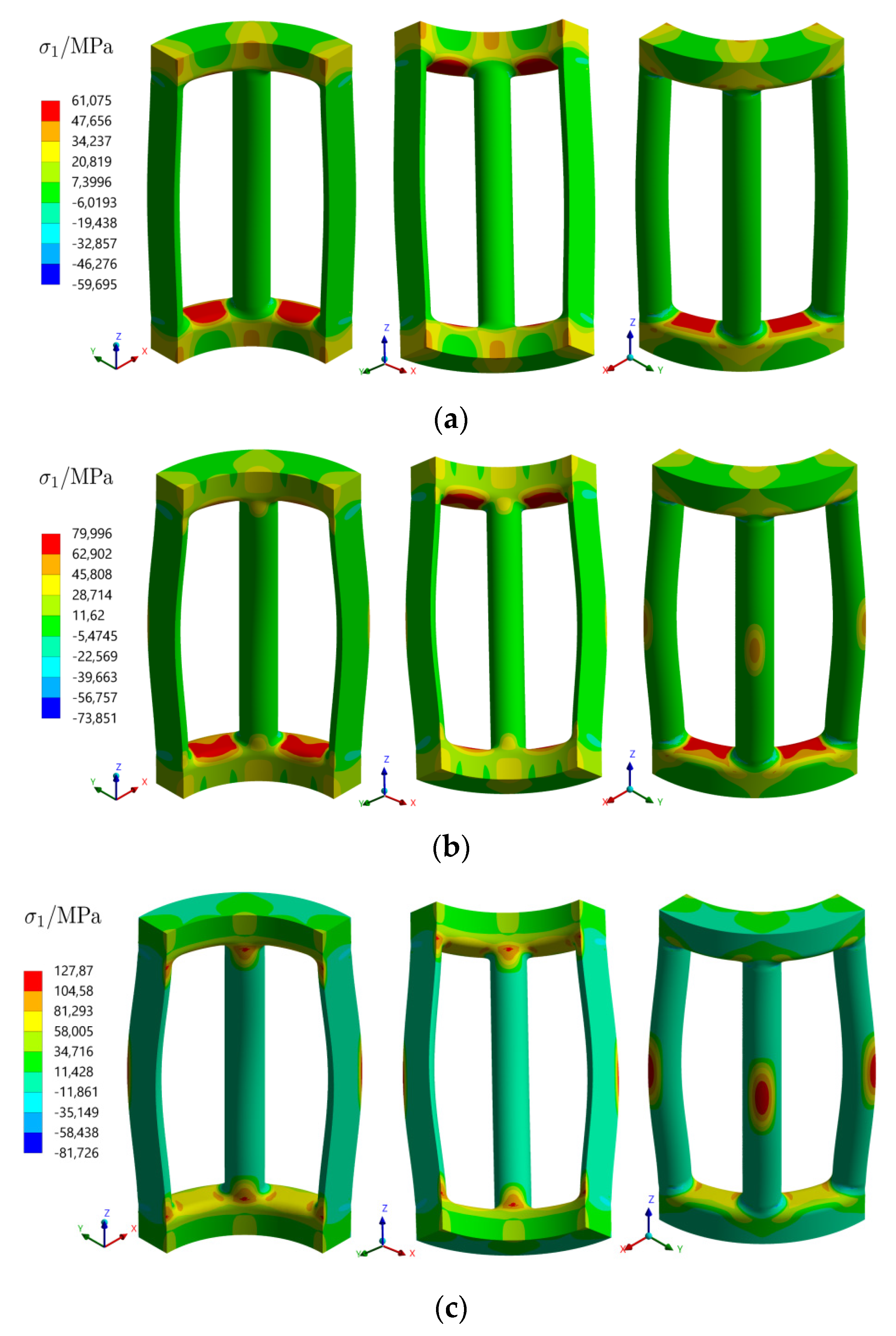
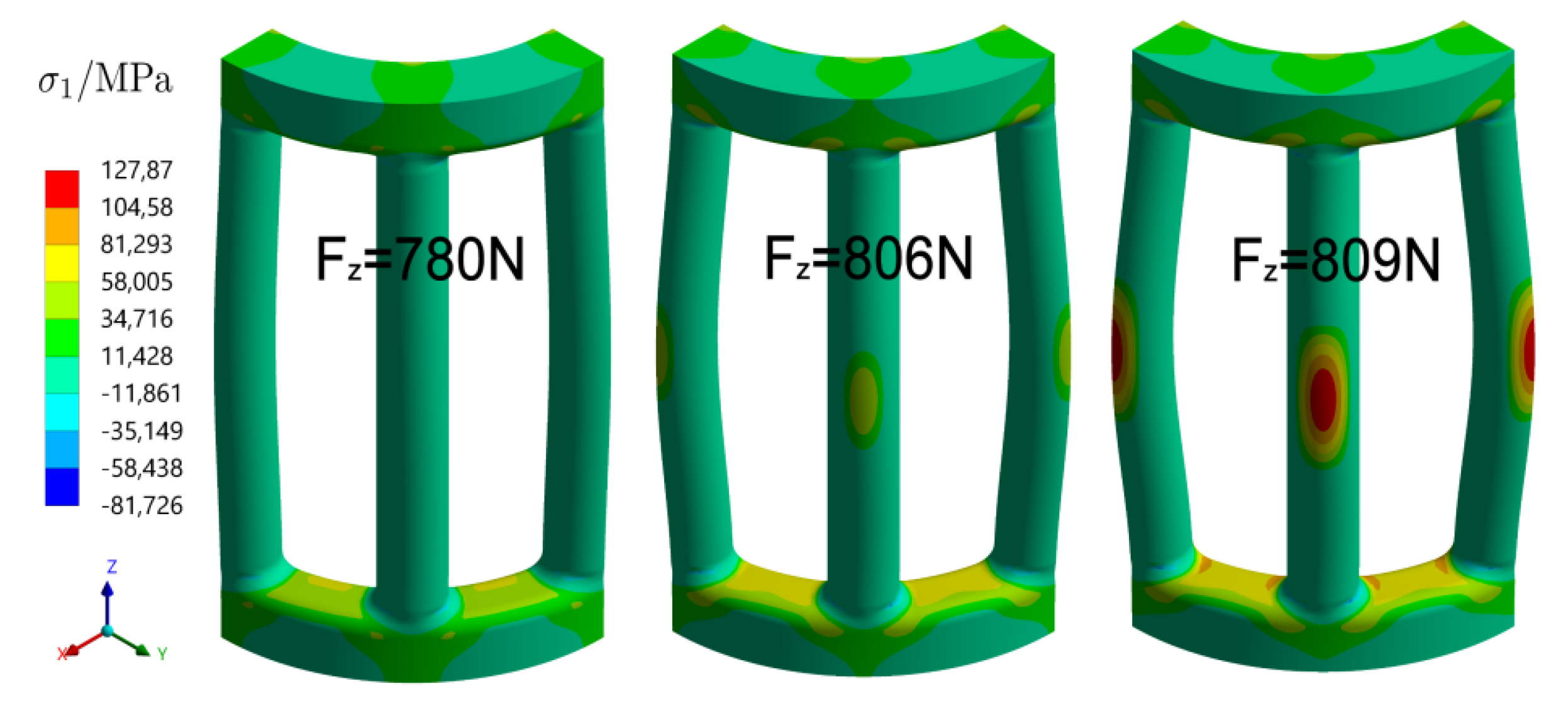
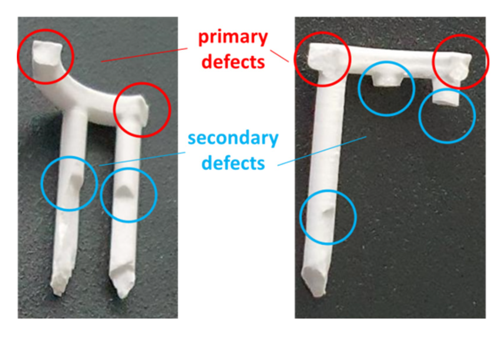
2.2. FE Analysis and Material Failure Model
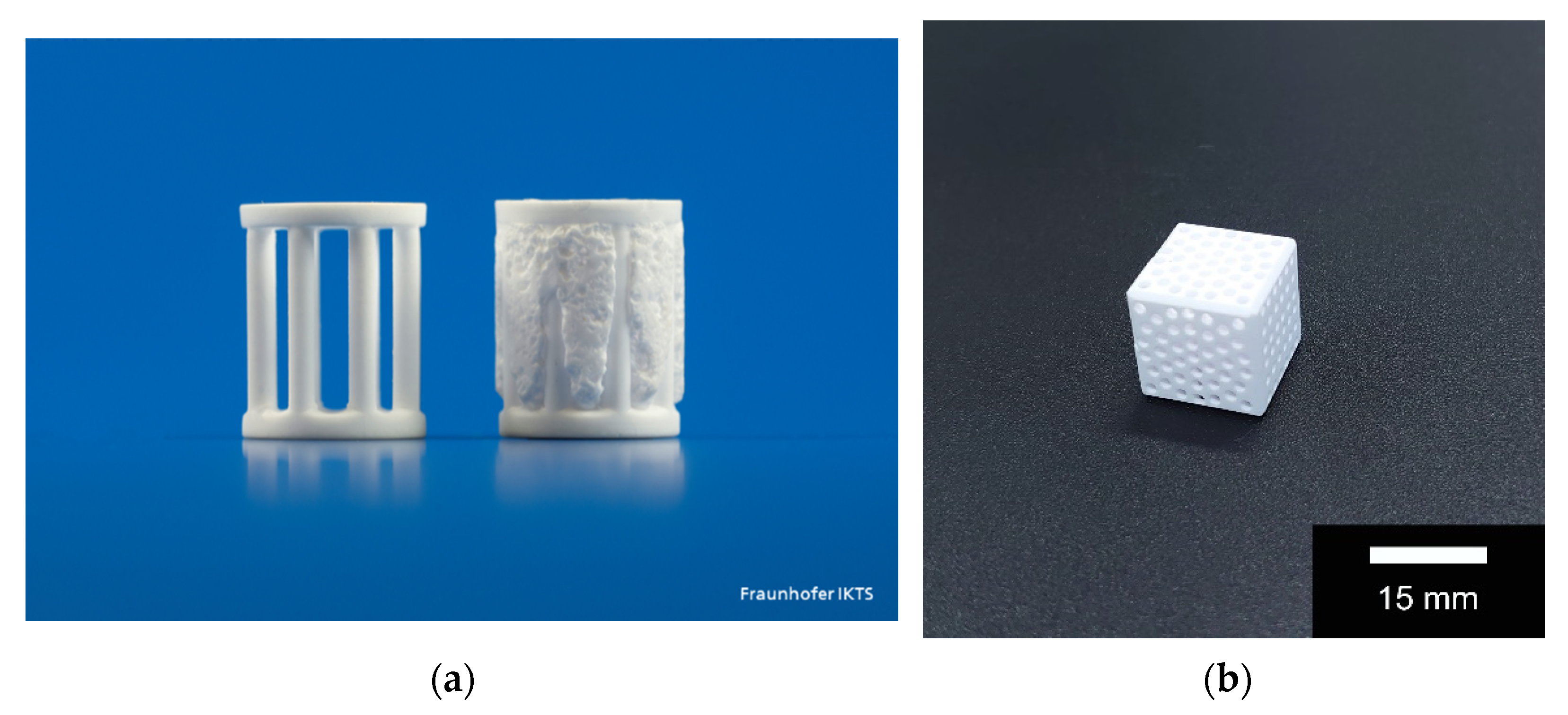
2.3. CerAM VPP
2.4. Mold Filling, Hybridization and Part Characterization
2.5. In Vitro Biocompatibility
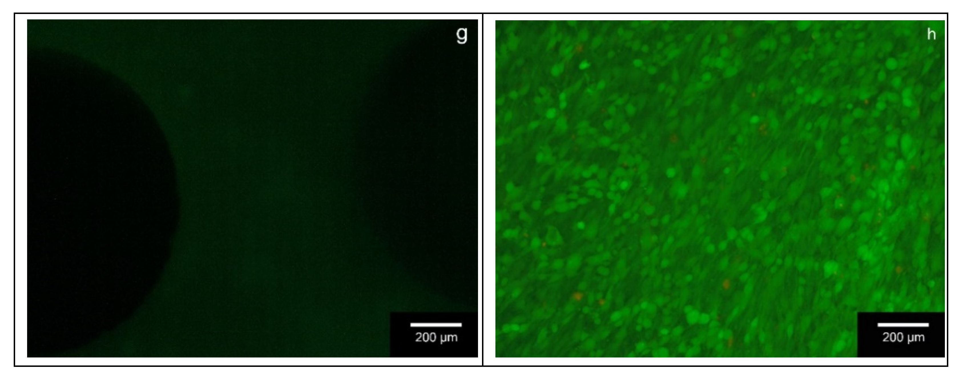
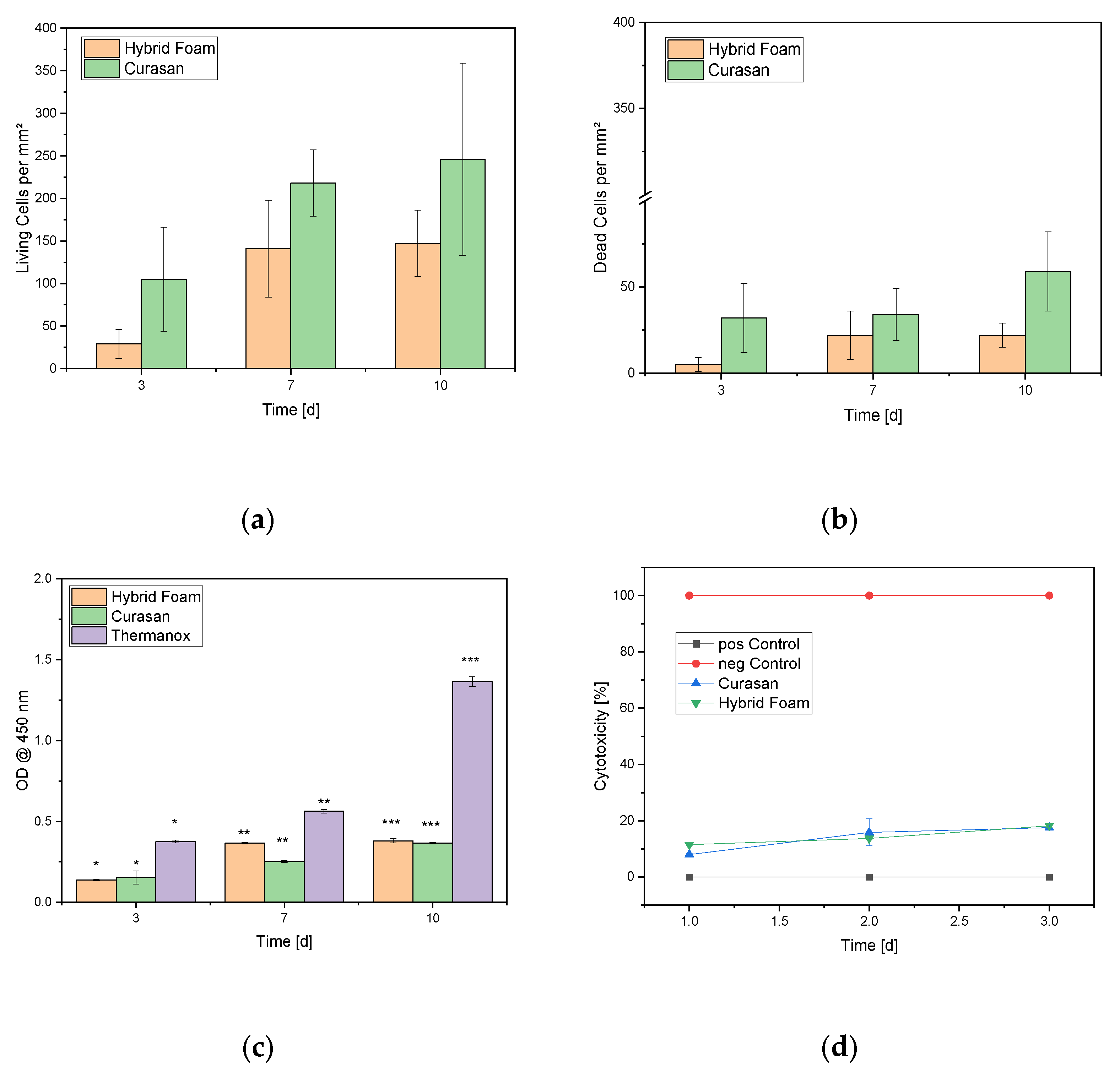
2.5.1. Live/Dead Assay
2.5.2. Cell Proliferation Assay
2.5.3. Lactate Dehydrogenase (LDH) Assay
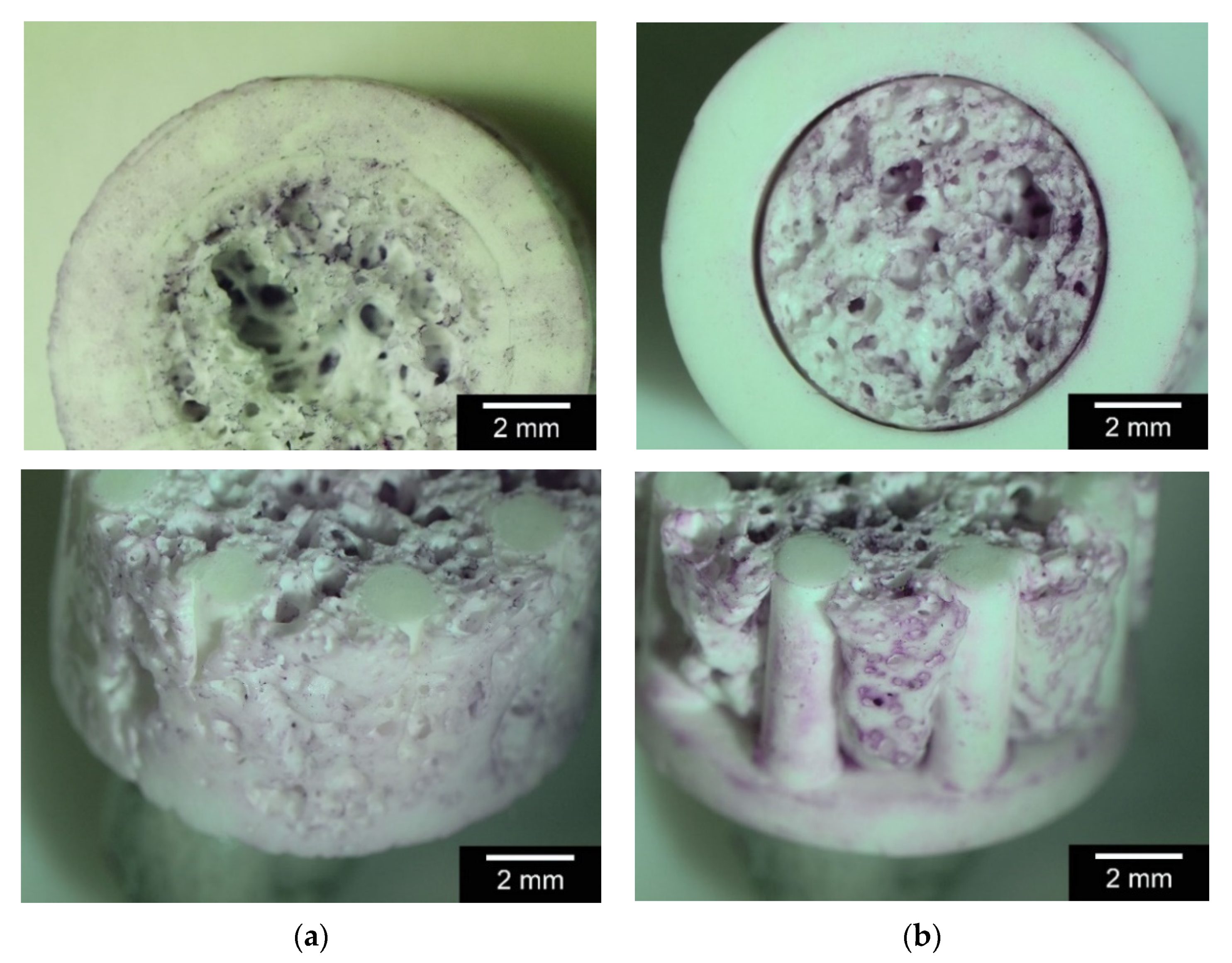
2.5.4. GIEMSA Staining
2.6. In Vivo Preparations
- 0 = no
- 1 = minimal
- 2 = minimal–moderate
- 3 = moderate
- 4 = moderate–high
- 5 = high
2.7. Statistics
3. Results
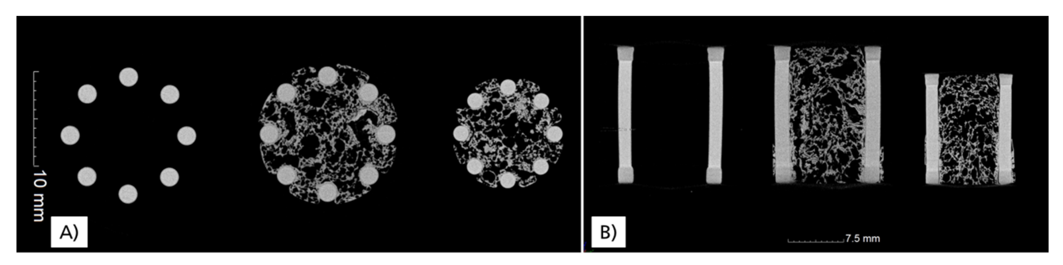
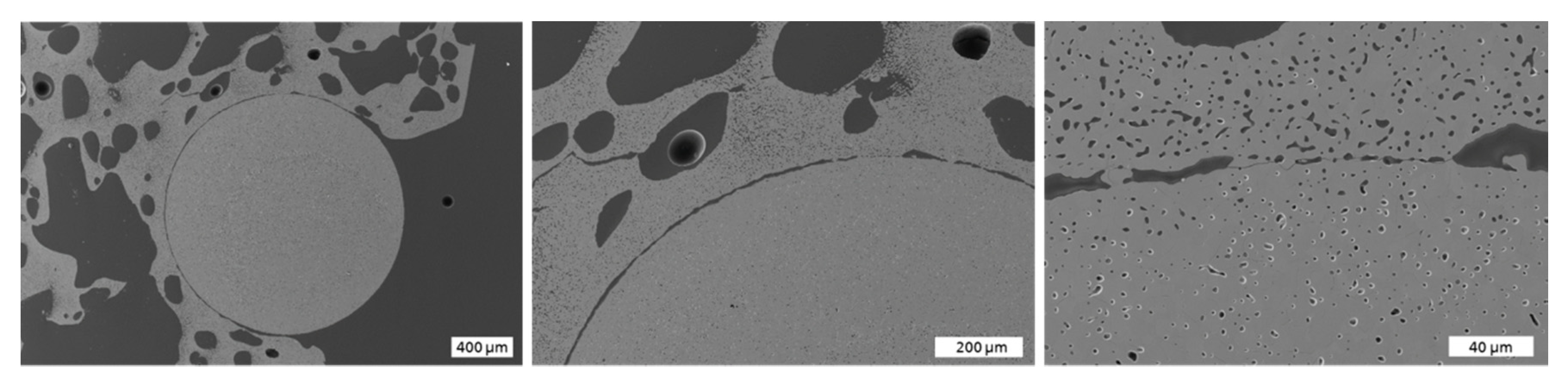
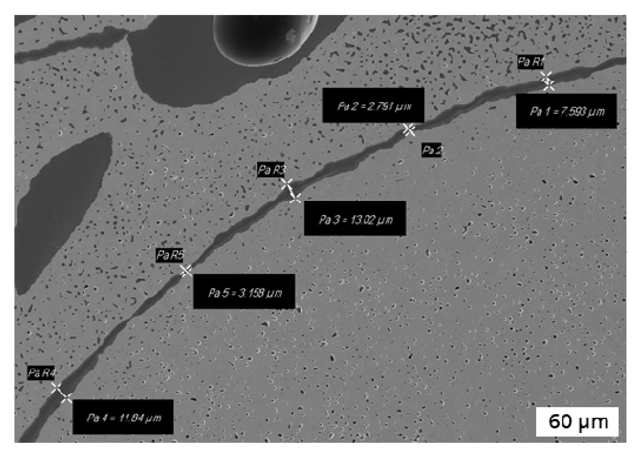
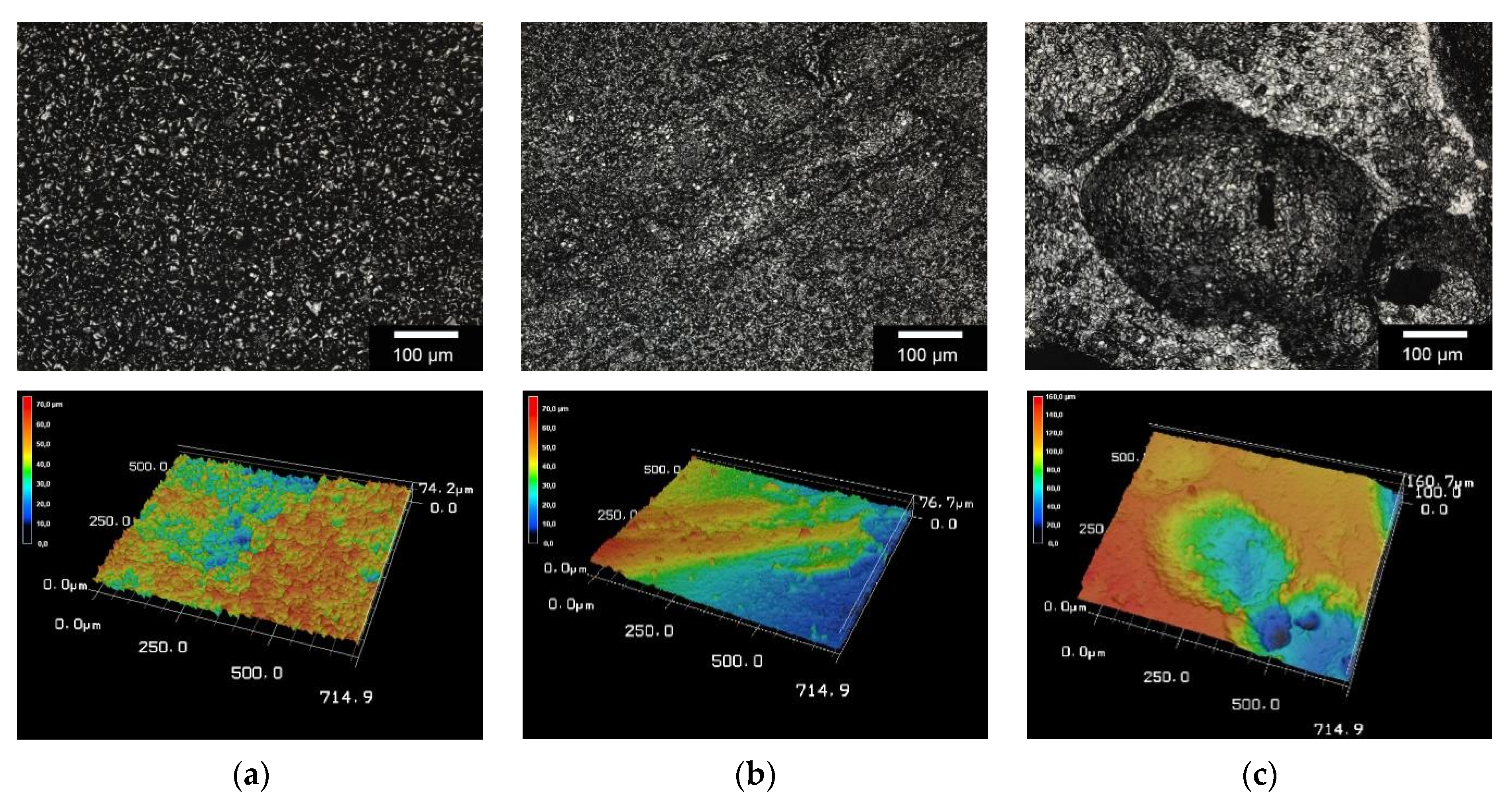
3.1. Microstructural Characterization
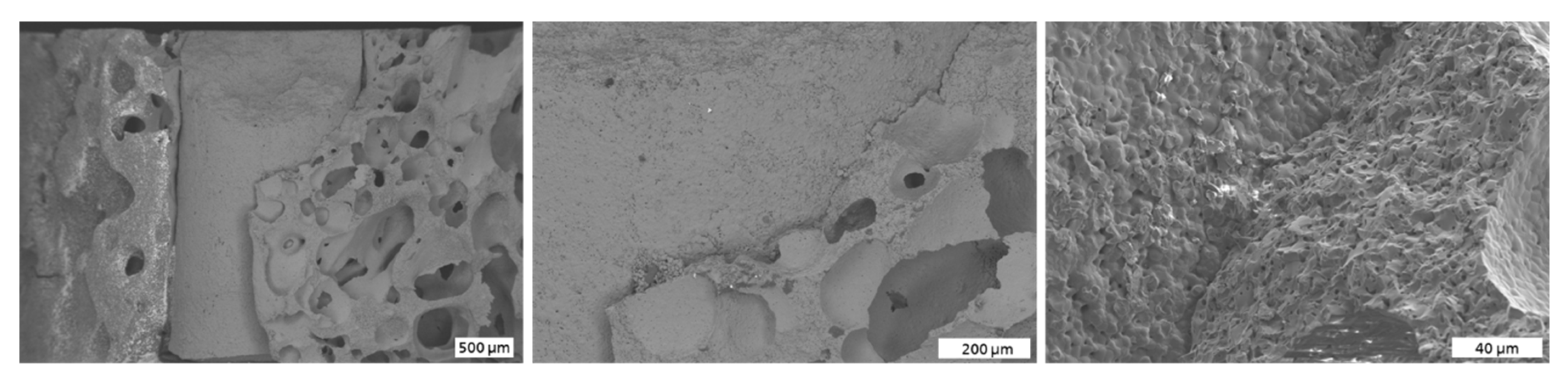
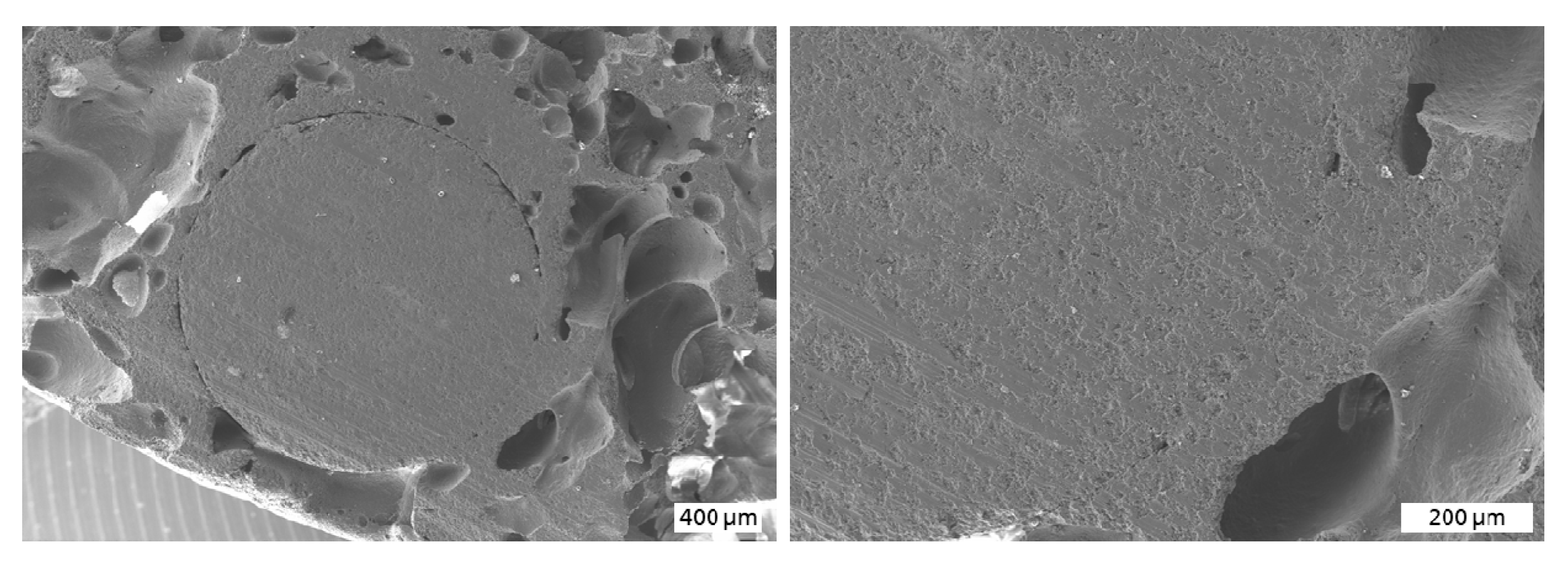
3.2. Mechanical Characterization and Comparison to FE Simulation
3.3. In Vitro Biocompatibility
3.3.1. Live/Dead Assay
3.3.2. Cell Proliferation Assay
3.3.3. LDH Assay
3.3.4. GIEMSA Staining
3.4. In Vivo Studies
- Clinical Examination
- b.
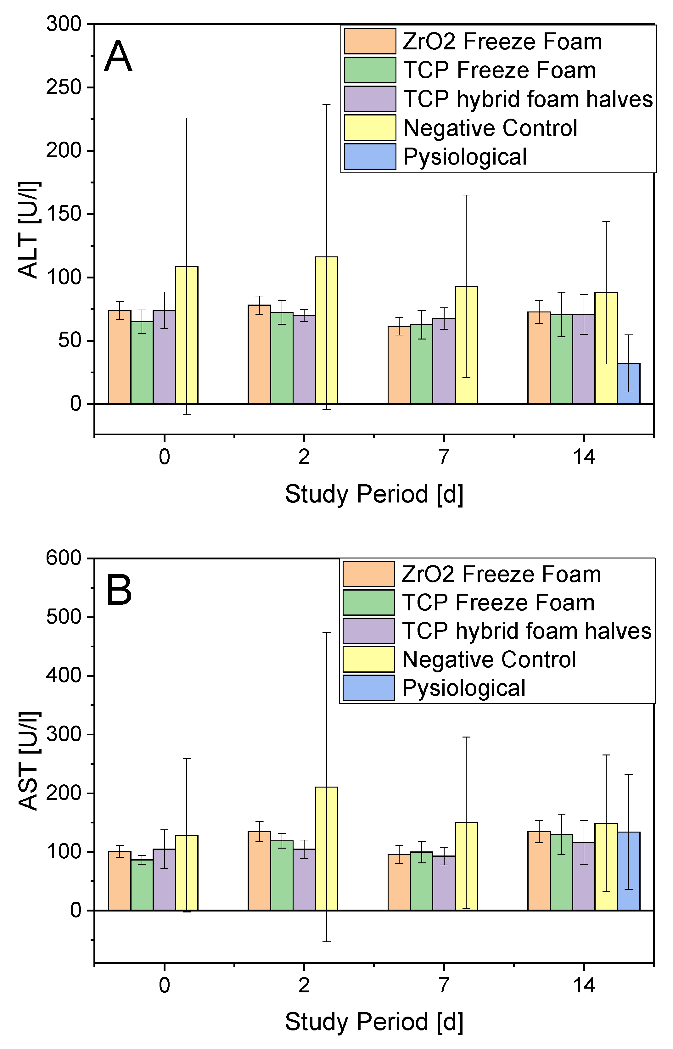
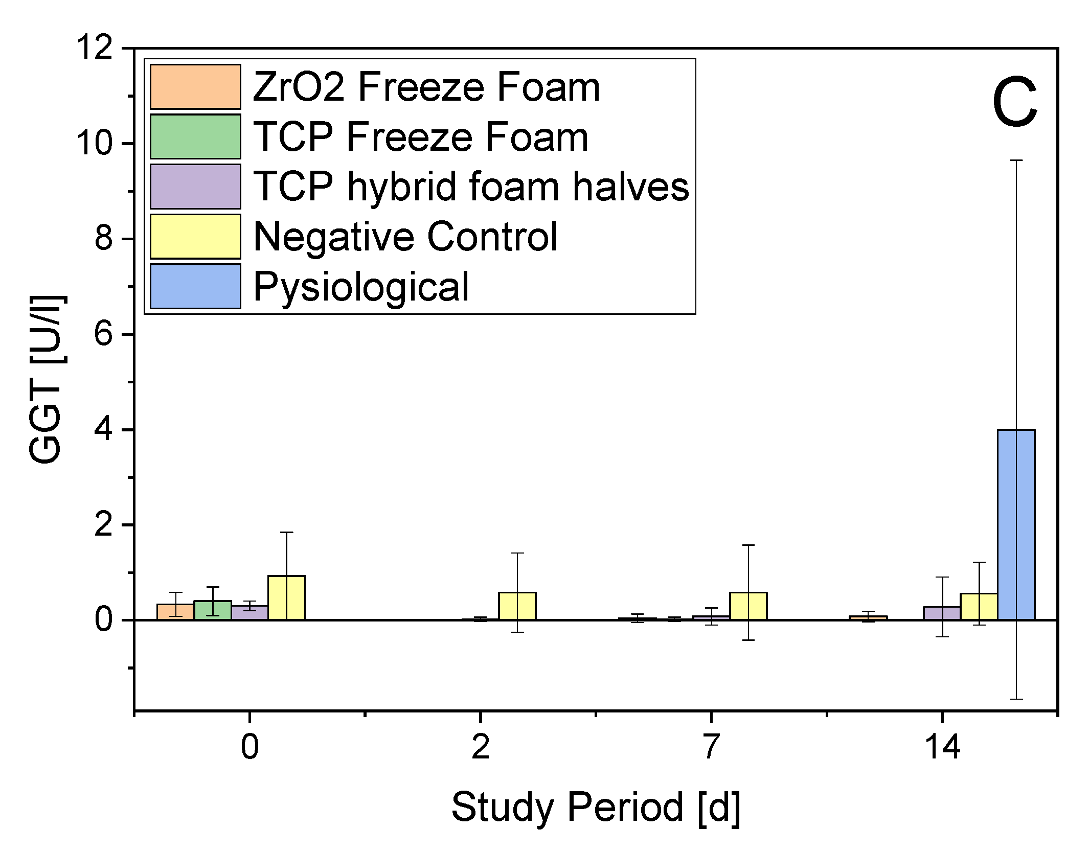
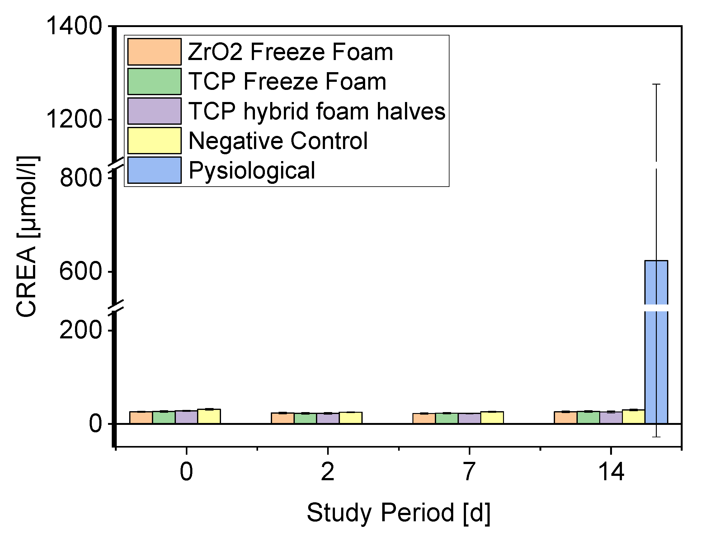
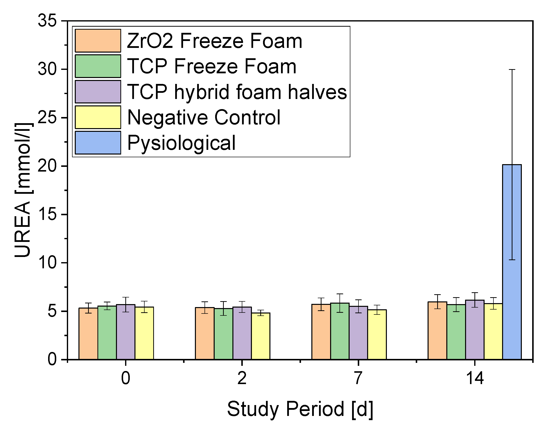
- Serum Parameters
3.4.1. ALT
3.4.2. Creatinine
3.4.3. Necropsy
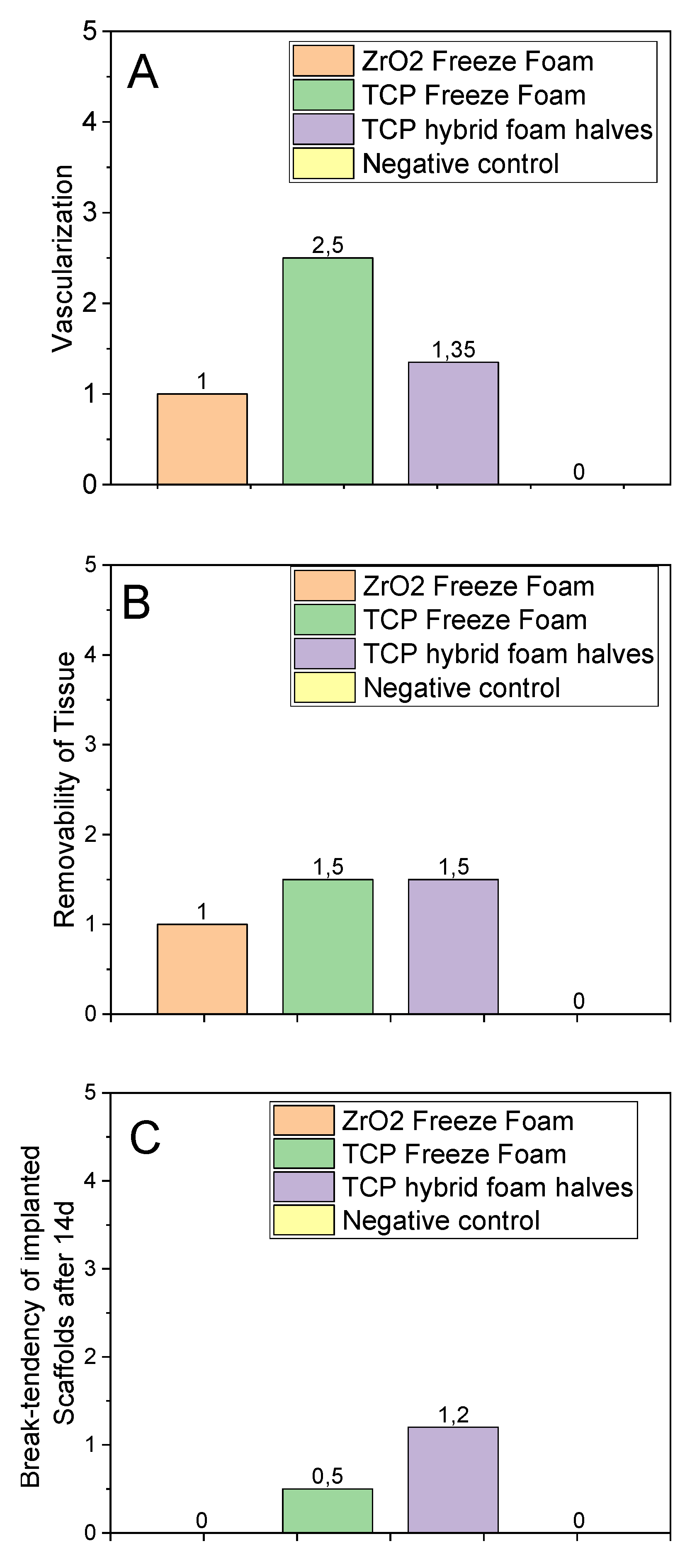
3.4.4. Implant Parameters
3.4.5. In Vivo Conclusion
4. Discussion
4.1. Microstructural and Mechanical Characterization
4.2. Biocompatibility
5. Conclusions
Author Contributions
Funding
Institutional Review Board Statement
Informed Consent Statement
Acknowledgments
Conflicts of Interest
References
- Mills, L.A.; Aitken, S.A.; Simpson, A.H.R.W. The risk of non-union per fracture: Current myths and revised figures from a population of over 4 million adults. Acta Orthop. 2017, 88, 434–439. [Google Scholar] [CrossRef] [PubMed] [Green Version]
- Solomon, D.H.; Patrick, A.R.; Schousboe, J.; Losina, E. The potential economic benefits of improved postfracture care: A cost-effectiveness analysis of a fracture liaison service in the us health-care system. J. Bone Miner. Res. 2014, 29, 1667–1674. [Google Scholar] [CrossRef] [Green Version]
- Burge, R.; Dawson-Hughes, B.; Solomon, D.H.; Wong, J.B.; King, A.; Tosteson, A. Incidence and economic burden of osteoporosis-related fractures in the united states, 2005–2025. J. Bone Miner. Res. Off. J. Am. Soc. Bone Miner. Res. 2007, 22, 465–475. [Google Scholar] [CrossRef] [PubMed]
- Gómez-Barrena, E.; Rosset, P.; Lozano, D.; Stanovici, J.; Ermthaller, C.; Gerbhard, F. Bone fracture healing: Cell therapy in delayed unions and nonunions. Bone 2015, 70, 93–101. [Google Scholar] [CrossRef] [Green Version]
- Dimitriou, R.; Jones, E.; McGonagle, D.; Giannoudis, P.V. Bone regeneration: Current concepts and future directions. BMC Med. 2011, 9, 66. [Google Scholar] [CrossRef] [PubMed] [Green Version]
- Reichert, J.C.; Wullschleger, M.E.; Cipitria, A.; Lienau, J.; Cheng, T.K.; Schütz, M.A.; Duda, G.N.; Nöth, U.; Eulert, J.; Hutmacher, D.W. Custom-made composite scaffolds for segmental defect repair in long bones. Int. Orthop. 2011, 35, 1229–1236. [Google Scholar] [CrossRef] [Green Version]
- de Grado, G.F.; Keller, L.; Idoux-Gillet, Y.; Wagner, Q.; Musset, A.-M.; Benkirane-Jessel, N.; Bornert, F.; Offner, D. Bone substitutes: A review of their characteristics, clinical use, and perspectives for large bone defects management. J. Tissue Eng. 2018, 9, 2041731418776819. [Google Scholar] [CrossRef] [Green Version]
- Fishman, J.A.; Scobie, L.; Takeuchi, Y. Xenotransplantation-associated infectious risk: A who consultation. Xenotransplantation 2012, 19, 72–81. [Google Scholar] [CrossRef] [PubMed] [Green Version]
- Zwingenberger, S.; Nich, C.; Valladares, R.D.; Yao, Z.; Stiehler, M.; Goodman, S.B. Recommendations and considerations for the use of biologics in orthopedic surgery. BioDrugs 2012, 26, 245–256. [Google Scholar] [CrossRef]
- Takemoto, M.; Fujibayashi, S.; Neo, M.; Suzuki, J.; Kokubo, T.; Nakamura, T. Mechanical properties and osteoconductivity of porous bioactive titanium. Biomaterials 2005, 26, 6014–6023. [Google Scholar] [CrossRef]
- Rainer, A.; Giannitelli, S.M.; Abbruzzese, F.; Traversa, E.; Licoccia, S.; Trombetta, M. Fabrication of bioactive glass–ceramic foams mimicking human bone portions for regenerative medicine. Acta Biomater. 2008, 4, 362–369. [Google Scholar] [CrossRef]
- Voss, P.; Sauerbier, S.; Wiedmann-Al-Ahmad, M.; Zizelmann, C.; Stricker, A.; Schmelzeisen, R.; Gutwald, R. Bone regeneration in sinus lifts: Comparing tissue-engineered bone and iliac bone. Br. J. Oral Maxillofac. Surg. 2010, 48, 121–126. [Google Scholar] [CrossRef] [PubMed]
- LeGeros, R.Z. Properties of osteoconductive biomaterials: Calcium phosphates. Clin. Orthop. Relat. Res. 2002, 395, 81–98. [Google Scholar] [CrossRef] [PubMed]
- Miranda, P.; Saiz, E.; Gryn, K.; Tomsia, A.P. Sintering and robocasting of β-tricalcium phosphate scaffolds for orthopaedic applications. Acta Biomater. 2006, 2, 457–466. [Google Scholar] [CrossRef] [PubMed]
- Bernstein, A.; Nobel, D.; Mayr, H.O.; Berger, G.; Gildenhaar, R.; Brandt, J. Histological and histomorphometric investigations on bone integration of rapidly resorbable calcium phosphate ceramics. J. Biomed. Mater. Res. B Appl. Biomater. 2008, 84, 452–462. [Google Scholar] [CrossRef]
- Mayr, H.O.; Dietrich, M.; Fraedrich, F.; Hube, R.; Nerlich, A.; von Eisenhart-Rothe, R.; Hein, W.; Bernstein, A. Microporous pure beta-tricalcium phosphate implants for press-fit fixation of anterior cruciate ligament grafts: Strength and healing in a sheep model. Arthrosc. J. Arthrosc. Relat. Surg. 2009, 25, 996–1005. [Google Scholar] [CrossRef]
- Mayr, H.O.; Klehm, J.; Schwan, S.; Hube, R.; Südkamp, N.P.; Niemeyer, P.; Salzmann, G.; von Eisenhardt-Rothe, R.; Heilmann, A.; Bohner, M.; et al. Microporous calcium phosphate ceramics as tissue engineering scaffolds for the repair of osteochondral defects: Biomechanical results. Acta Biomater. 2013, 9, 4845–4855. [Google Scholar] [CrossRef]
- Mayr, H.O.; Suedkamp, N.P.; Hammer, T.; Hein, W.; Hube, R.; Roth, P.V.; Bernstein, A. Beta-tricalcium phosphate for bone replacement: Stability and integration in sheep. J. Biomech. 2015, 48, 1023–1031. [Google Scholar] [CrossRef]
- Kuiper, J.H. Numerical Optimization of Artificial Hip Joint Designs; Radboud University Nijmegen: Nijmegen, The Netherlands, 1993. [Google Scholar]
- Paul, J.P. Strength requirements for internal and external prostheses. J. Biomech. 1999, 32, 381–393. [Google Scholar] [CrossRef]
- Clarke, B. Normal bone anatomy and physiology. Clin. J. Am. Soc. Nephrol. 2008, 3, S131. [Google Scholar] [CrossRef] [Green Version]
- Alaribe, F.N.; Manoto, S.L.; Motaung, S.C.K.M. Scaffolds from biomaterials: Advantages and limitations in bone and tissue engineering. Biologia 2016, 71, 353–366. [Google Scholar] [CrossRef]
- Rustom, L.E.; Poellmann, M.J.; Johnson, A.J.W. Mineralization in micropores of calcium phosphate scaffolds. Acta Biomater. 2019, 83, 435–455. [Google Scholar] [CrossRef]
- Park, S.A.; Lee, S.H.; Kim, W.D. Fabrication of porous polycaprolactone/hydroxyapatite (pcl/ha) blend scaffolds using a 3d plotting system for bone tissue engineering. Bioprocess Biosyst. Eng. 2011, 34, 505–513. [Google Scholar] [CrossRef]
- Munoz-Pinto, D.J.; McMahon, R.E.; Kanzelberger, M.A.; Jimenez-Vergara, A.C.; Grunlan, M.A.; Hahn, M.S. Inorganic–organic hybrid scaffolds for osteochondral regeneration. J. Biomed. Mater. Res. Part A 2010, 94, 112–121. [Google Scholar] [CrossRef]
- Karl, S.; Somers, A.V. Method of Making Porous Ceramic Articles 1963. Google Patents.
- Nandi, S.K.; Fielding, G.; Banerjee, D.; Bandyopadhyay, A.; Bose, S. 3d printed β-tcp bone tissue engineering scaffolds: Effects of chemistry on in vivo biological properties in a rabbit tibia model. J. Mater. Res. 2018, 33, 1939–1947. [Google Scholar] [CrossRef] [PubMed]
- Ahlhelm, M.; Schwarzer, E.; Scheithauer, U.; Moritz, T.; Michaelis, A. Novel ceramic composites for personalized 3d structures. J. Ceram. Sci. Technol. 2017, 8, 91–100. [Google Scholar] [CrossRef]
- Ahlhelm, M.; Günther, P.; Scheithauer, U.; Schwarzer, E.; Günther, A.; Slawik, T.; Moritz, T.; Michaelis, A. Innovative and novel manufacturing methods of ceramics and metal-ceramic composites for biomedical applications. J. Eur. Ceram. Soc. 2016, 36, 2883–2888. [Google Scholar] [CrossRef]
- Willmann, G. Materialeigenschaften von hydroxylapatit-keramik. Mater. Und Werkst. 1992, 23, 107–110. [Google Scholar] [CrossRef]
- Ahlhelm, M. Entwicklung Zellularer Strukturen für Vielfältige Anwendungen; Fraunhofer Verlag: Dresden, Germany, 2016; ISBN 978-3-8396-0977-4. [Google Scholar]
- Živcová, Z.; Černý, M.; Pabst, W.; Gregorová, E. Elastic properties of porous oxide ceramics prepared using starch as a pore-forming agent. J. Eur. Ceram. Soc. 2009, 29, 2765–2771. [Google Scholar] [CrossRef]
- Trevisani, F.; Marco, F.D.; Capitanio, U.; Dell’Antonio, G.; Cinque, A.; Larcher, A.; Lucianò, R.; Bettiga, A.; Vago, R.; Briganti, A.; et al. Renal histology across the stages of chronic kidney disease. J. Nephrol. 2021, 34, 699–707. [Google Scholar] [CrossRef]
- Giknis, C. Clinical Laboratory Parameters for Crl:Wi (han); Charles Rivers Laboratories: Wilmington, MA, USA, 2008. [Google Scholar]
- Boehm, O.; Zur, B.; Koch, A.; Tran, N.; Freyenhagen, R.; Hartmann, M.; Zacharowski, K. Clinical chemistry reference database for wistar rats and C57/BL6 mice. Biol. Chem. 2007, 388, 547–554. [Google Scholar] [CrossRef]
- Ozer, J.; Ratner, M.; Shaw, M.; Bailey, W.; Schomaker, S. The current state of serum biomarkers of hepatotoxicity. Toxicology 2008, 245, 194–205. [Google Scholar] [CrossRef]
- Ramaiah, S.K. A toxicologist guide to the diagnostic interpretation of hepatic biochemical parameters. Food Chem. Toxicol. 2007, 45, 1551–1557. [Google Scholar] [CrossRef]
- Seidenstuecker, M.; Schmeichel, T.; Ritschl, L.; Vinke, J.; Schilling, P.; Schmal, H.; Bernstein, A. Mechanical properties of the composite material consisting of β-tcp and alginate-di-aldehyde-gelatin hydrogel and its degradation behavior. Materials 2021, 14, 1303. [Google Scholar] [CrossRef] [PubMed]
- Hart, N.H.; Nimphius, S.; Rantalainen, T.; Ireland, A.; Siafarikas, A.; Newton, R.U. Mechanical basis of bone strength: Influence of bone material, bone structure and muscle action. J. Musculoskelet. Neuron. Interact. 2017, 17, 114–139. [Google Scholar]
- Seidenstuecker, M.; Ruehe, J.; Suedkamp, N.P.; Serr, A.; Wittmer, A.; Bohner, M.; Bernstein, A.; Mayr, H.O. Composite material consisting of microporous β-tcp ceramic and alginate for delayed release of antibiotics. Acta Biomater. 2017, 51, 433–446. [Google Scholar] [CrossRef] [PubMed]
- Cai, S.; Wu, C.; Yang, W.; Liang, W.; Yu, H.; Liu, L. Recent advance in surface modification for regulating cell adhesion and behaviors. Nanotechnol. Rev. 2020, 9, 971–989. [Google Scholar] [CrossRef]
- Zhao, G.; Zinger, O.; Schwartz, Z.; Wieland, M.; Landolt, D.; Boyan, B.D. Osteoblast-like cells are sensitive to submicron-scale surface structure. Clin. Oral Implant. Res. 2006, 17, 258–264. [Google Scholar] [CrossRef]
- Bernstein, A.; Niemeyer, P.; Salzmann, G.; Südkamp, N.P.; Hube, R.; Klehm, J.; Menzel, M.; von Eisenhart-Rothe, R.; Bohner, M.; Görz, L.; et al. Microporous calcium phosphate ceramics as tissue engineering scaffolds for the repair of osteochondral defects: Histological results. Acta Biomater. 2013, 9, 7490–7505. [Google Scholar] [CrossRef]
- Misch, C.E.; Qu, Z.; Bidez, M.W. Mechanical properties of trabecular bone in the human mandible: Implications for dental implant treatment planning and surgical placement. J. Oral Maxillofac. Surg. 1999, 57, 700–706. [Google Scholar] [CrossRef]
- Morgan, E.F.; Unnikrisnan, G.U.; Hussein, A.I. Bone mechanical properties in healthy and diseased states. Annu. Rev. Biomed. Eng. 2018, 20, 119–143. [Google Scholar] [CrossRef] [PubMed]


| Load Case | Displacement/mm | Reaction Force/N | Maximum Principal Stress/MPa |
|---|---|---|---|
| 1st | −0.41 | 780 | 61 |
| 2nd | −0.45 | 806 | 80 |
| 3rd | −0.48 | 809 | 128 |
| Sample | Geometrical Porosity (%) | Porosity of the Foam Cells (%) | Fmax (N) | Compressive Strength (MPa) |
|---|---|---|---|---|
| Freeze Foam | 80 ± 0.5 | 76.1 ± 1.4 | 101 ± 53 | 0.9 ± 0.5 |
| Hybrid Foam | 74.4 ± 0.5 | 69.9 ± 0.9 | 2641 ± 452 | 23 ± 4 |
| VPP Column | 16.5 ± 0.7 * | 3199 ± 831 | 31 ± 8 | |
| Curasan | 55 ± 2 * | 693 ± 89 | 3 ± 0.4 |
Publisher’s Note: MDPI stays neutral with regard to jurisdictional claims in published maps and institutional affiliations. |
© 2021 by the authors. Licensee MDPI, Basel, Switzerland. This article is an open access article distributed under the terms and conditions of the Creative Commons Attribution (CC BY) license (https://creativecommons.org/licenses/by/4.0/).
Share and Cite
Ahlhelm, M.; Latorre, S.H.; Mayr, H.O.; Storch, C.; Freytag, C.; Werner, D.; Schwarzer-Fischer, E.; Seidenstücker, M. Mechanically Stable β-TCP Structural Hybrid Scaffolds for Potential Bone Replacement. J. Compos. Sci. 2021, 5, 281. https://doi.org/10.3390/jcs5100281
Ahlhelm M, Latorre SH, Mayr HO, Storch C, Freytag C, Werner D, Schwarzer-Fischer E, Seidenstücker M. Mechanically Stable β-TCP Structural Hybrid Scaffolds for Potential Bone Replacement. Journal of Composites Science. 2021; 5(10):281. https://doi.org/10.3390/jcs5100281
Chicago/Turabian StyleAhlhelm, Matthias, Sergio H. Latorre, Hermann O. Mayr, Christiane Storch, Christian Freytag, David Werner, Eric Schwarzer-Fischer, and Michael Seidenstücker. 2021. "Mechanically Stable β-TCP Structural Hybrid Scaffolds for Potential Bone Replacement" Journal of Composites Science 5, no. 10: 281. https://doi.org/10.3390/jcs5100281