Structural Health Monitoring for Advanced Composite Structures: A Review


1
Department Aeronautics, Polytechnic University of Madrid, 28040 Madrid, Spain
2
Ingeniería Aeroespacial, Universidad Pontificia Bolivariana, Medellín 050031, Colombia
*
Author to whom correspondence should be addressed.
J. Compos. Sci. 2020, 4(1), 13; https://doi.org/10.3390/jcs4010013
Submission received: 26 December 2019
/
Revised: 20 January 2020
/
Accepted: 21 January 2020
/
Published: 27 January 2020
(This article belongs to the Special Issue Feature Papers in Journal of Composites Science in 2019)
Abstract
:Condition-based maintenance refers to the installation of permanent sensors on a structure/system. By means of early fault detection, severe damage can be avoided, allowing efficient timing of maintenance works and avoiding unnecessary inspections at the same time. These are the goals for structural health monitoring (SHM). The changes caused by incipient damage on raw data collected by sensors are quite small, and are usually contaminated by noise and varying environmental factors, so the algorithms used to extract information from sensor data need to focus on sensitive damage features. The developments of SHM techniques over the last 20 years have been more related to algorithm improvements than to sensor progress, which essentially have been maintained without major conceptual changes (with regards to accelerometers, piezoelectric wafers, and fiber optic sensors). The main different SHM systems (vibration methods, strain-based fiber optics methods, guided waves, acoustic emission, and nanoparticle-doped resins) are reviewed, and the main issues to be solved are identified. Reliability is the key question, and can only be demonstrated through a probability of detection (POD) analysis. Attention has only been paid to this issue over the last ten years, but now it is a growing trend. Simulation of the SHM system is needed in order to reduce the number of experiments.
1. Introduction
Structural Health Monitoring (SHM) is defined as “the process of acquiring and analysing data from on-board sensors to evaluate the health of a structure”; this definition was taken from the SAE Standard ARP6461 as a consensus among the participants at the Aerospace Industry Steering Committee on Structural Health Monitoring, and was composed by representatives of the main industries and universities active on SHM.
SHM systems include three key elements:
- A network of sensors, permanently attached to the structure. This aspect establishes the main difference from conventional non-destructive testing (NDT) procedures, and is essential for performing automated inspections.
- On-board data handling and computing facilities. The high number of sensors continuously produces a large amount of data to be processed in real-time. SHM was feasible when large-capacity PCs were available (in the mid-1980s).
- Algorithms that compare stored data from the pristine structure with recently acquired data, after correcting for environmental factors, to calculate a damage index and to inform about damage existence, localization, and type.
Conventional NDT procedures like ultrasonics, X-rays, or thermography, among others, have as their main objective the detection of cracks and discontinuities inside materials or at their surfaces for quality control of newly manufactured components and quality assurance during service. Their reliability has been firmly demonstrated. Their differences from SHM techniques are clear. They are more mature technologies, but require human intervention, and consequently have higher labour costs; they require access to structural parts with external probes or equipment; and they are not suited for condition-based maintenance (CBM) concepts. However, automation and new inspection technologies are making the distinction less neat, and now both are considered under the common term non-destructive evaluation (NDE). A recent survey [1] may be a source of complementary information on these NDE technologies.
Prognosis, or the process of forecasting the remaining useful life of a structure, is closely linked to Diagnosis, or the evaluation of structural health, which is the main objective of SHM. Both concepts differ in the tools they use: prognosis is mainly focused on statistical analysis, while diagnosis is more related to sensors, signal processing, and algorithms for damage identification. However, the relationship between both concepts and synergy potentials are very strong, and some authors consider Prognosis to be the fifth level of SHM (levels one to four are damage detection, localization, classification, and quantification of damage, respectively).
2. Benefits of Structural Health Monitoring
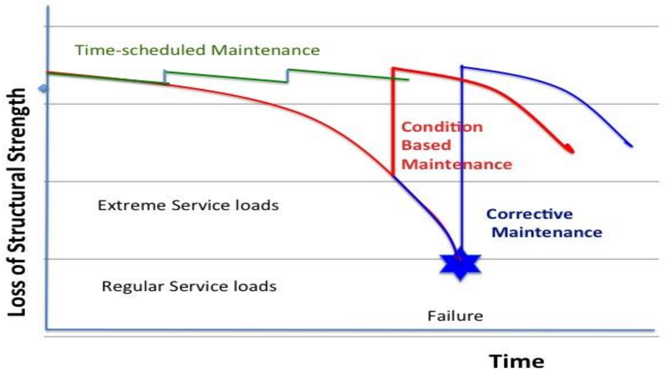
To highlight the benefits of implementing SHM, Figure 1 illustrates the degradation process experienced in service for every structure/mechanical system. By improving the material’s properties, and particularly the material’s toughness, the slope of the curve is decreased and the durability of the structure is increased. Besides acquisition costs, the second main factor that influences life cycle costs (LCC) is related to the maintenance or actions needed to keep and recover the structure within a satisfactory state, after incipient damages.
Three alternatives for maintenance are feasible [2]:
- The purely corrective maintenance strategy, which involves doing nothing until failure is clearly visible; it has the advantage of having the lowest initial costs. Among its disadvantages, besides the risk of catastrophic failure, are the fact that damage growth by usage occurs faster and faster, meaning repairing costs may be higher; the structure will be out of service at an unpredictable date, so maintenance cannot be scheduled. It is only acceptable for low responsibility, very lightly loaded structures (the level of service loads and overloads also influences the slope of the degradation curve).
- Time-based maintenance, which involves regular inspection periods which are visual or supported by NDT methods and which require access to the structure and maybe disassembly. This is the procedure currently employed in aerospace and also for large wind turbine blades; once a year, an industrial climber ropes from the rotor and inspects the leading and the trailing edge of the blade. This approach has allowed the aircraft industry to reach a very high safety level, and the risk of accident due to structural failures is extremely low; however, the impact of these repeated inspections on the LCC is significant, with it even equalling the acquisition costs.
- Condition-based maintenance refers to the installation of permanent sensors on the structure/system. By means of early fault detection, severe damage can be avoided, and maintenance works can be scheduled to avoid inconvenient stop-times. With time-scheduled maintenance very often the only result from the inspection is the verification of the non-existence of damage; CBM maintenance works are only performed when there is a risk to the structure.
CBM has been fully implemented for rotating machinery since the 1990s, with significant savings in maintenance and avoidance of catastrophic accidents achieved. Just by permanently fixing a few sensors (accelerometers) at adequate points (bearing supports), and with a basic algorithm—the fast Fourier transform (FFT)—which may be complemented with an additional expert system to recognize changes in the spectral response, CBM is able to identify any mechanical misfunctioning, like the wearing or cracking of rolling tracks, by affording an early warning in critical structures, like the drive train of helicopters, or allowing unattended operation of remote power plants (in this case the system automatically stops the machine in the case of an alarm, asking for maintenance).
Nevertheless, an equivalent concept for fixed structures called structural health monitoring has not reached a similar level of maturity, and most of its available techniques have a Technology Readiness Level (TRL) 3–5 according to a report from Sandia National Labs [3].
A quite useful discussion about the difficulties of translating results from laboratory to industrial applications was recently performed by Cawley [4]. He concluded that there are three main reasons for the slow adoption by industry: the lack of attention to the business case for monitoring (the technology is possibly available but the economic benefits are not clear enough); the fact that the methods need to be validated on real structures, under realistic service conditions; and the fact that methods have to be proven to be robust, need to be demonstrated on different structures and load cases, and need to afford understandable information to the structural engineer.
3. Classification of SHM Technologies
SHM technologies may be classified as local techniques when the area under surveillance is limited to the area under the sensor (this is the case for comparative vacuum monitoring (CVM) and also for electro-mechanical impedance (EMI)) and global techniques when damage can be detected anywhere in the structure by a network of sensors which is adequately distributed. Only modal analysis can be said to completely cover the whole structure; in many other cases, like inspection by guided waves, the area covered extends a few meters away from the sensors, but for whole coverage, many sensors are needed.
Technologies are sometimes classified by sensor type (piezoelectric wafers PZT, fiber optic sensors, accelerometers, and MEMS, etc.), but the same type of sensors may be used for several techniques, so it is better to classify technologies by their physical underlying principle, similarly to how it is done for NDT procedures.
Not all the listed techniques in Table 1 have similar importance; a Scopus search (performed in December 2019) using the search terms “vibration method structural health monitoring” showed the production of about 300 new documents per year with a rather stable rate over the last five years. The same was found for “guided waves SHM”. There were approximately 120 docs per year for “fiber optic sensors SHM”, and a number between 10 and 30 for the other categories. The total volume of published research on “composites SHM” has exceeded 6000 documents over the last ten years, which demonstrates high activity. Some of the most cited references for each technique are included in the table; a discussion on recent papers, restricted to the last five years, is given later in this article.
State of the art for SHM can be found in general textbooks [41,42], and even more favorably, in the proceedings of the biennial International Workshops on SHM (IWSHM) and European Workshops on SHM (EWSHM) conferences. Recent EWSHM proceedings are available at the website www.ndt.net, under a Creative Commons license.
4. In-Service Damages in Composite Structures
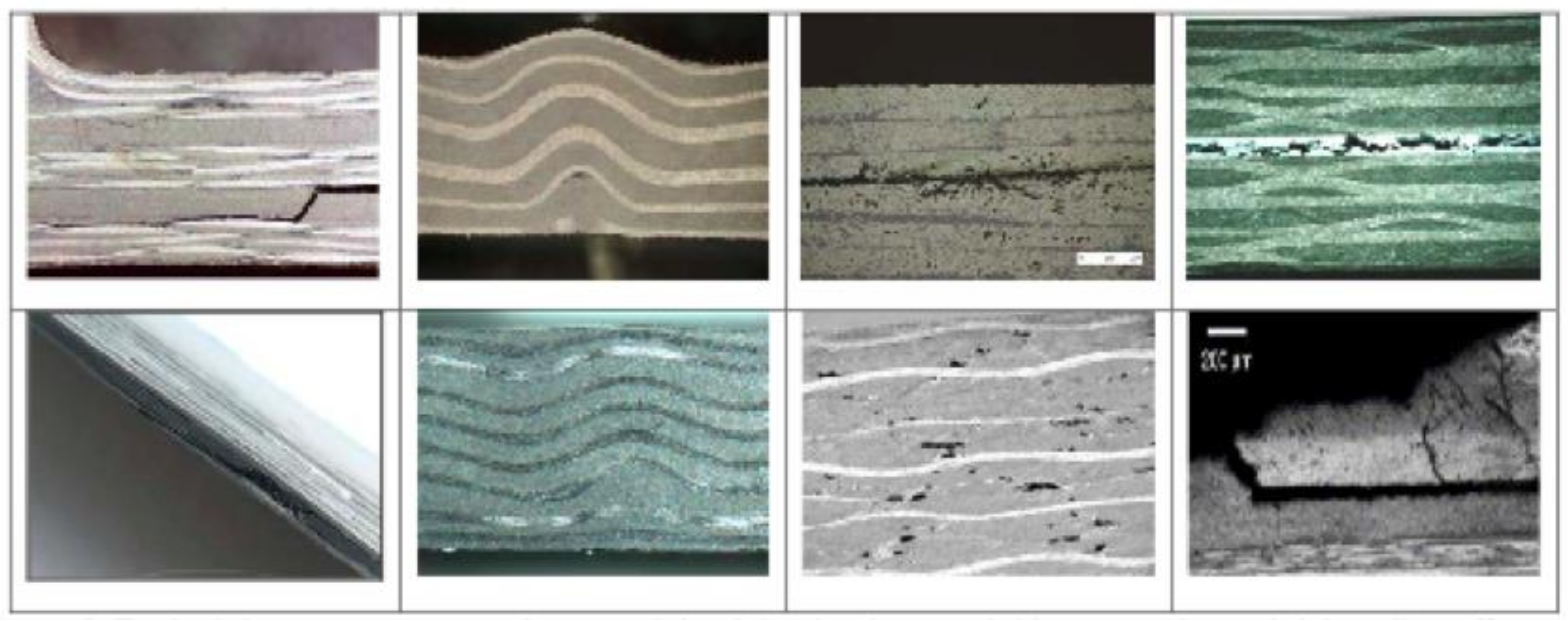
The usage of advanced composite structures has required the development of advanced NDT procedures to cover both manufacturing defects and the damages that happen during service. The most typical defects/damages that may appear in polymeric composite laminates are (Figure 2):
Single and multiple delaminations: This is a separation between two or more layers. It is the most frequent type of damage for composite materials. It may appear due to residual stresses during the manufacturing phase or due to low-velocity impacts during machining or in-service.
Foreign object inclusions: This is the separation between layers due to the inclusion of external materials between layers. It has a similar effect to a single delamination.
Interlaminar voids: This describes a large pore that remains unfilled with flat internal surfaces. It is induced by contamination between layers during manufacturing or trapped air due to incorrect debulking/curing. It has a similar effect to a single delamination.
Porosity: This consists of small trapped air bubbles inside the plies due to a lack of pressure during the curing. The effect is the reduction of effective stiffness and strength ply properties.
Fiber waviness and wrinkles are considered here as severe in-plane or out-of-plane multiple-ply waviness typically caused by the improper preparation and curing of thick laminates.
Debondings: This describes extensive separation between two elements, typically between the stiffener and the skin in aeronautic structures.
Every composite structural part or subcomponent to be installed into an aircraft has to pass a quality inspection before assembly which is usually performed by point scanning ultrasonics inspection, either by an automated C-scan or manually with the help of external probes, in the case of complex shapes. Current NDT inspection systems are able to locate defects as small as those 2 mm in diameter, a limit which is very difficult to attain using any SHM system. Other composite structures like wind turbine blades have less severe limits, but still have to follow a detailed inspection after manufacturing.
The goal for SHM, however, is not to compete with NDT procedures to detect manufacturing defects, but to detect damages that may happen during service; these will be large delaminations and debondings. For routine maintenance inspections, SHM offers the advantage that sensors are already located within the structure, meaning there is no need to have an operator moving an ultrasonic probe onto the surface or handling a thermography camera to obtain local images. Inspection by SHM can be performed without disassembling the structures, including hidden parts, without human intervention.
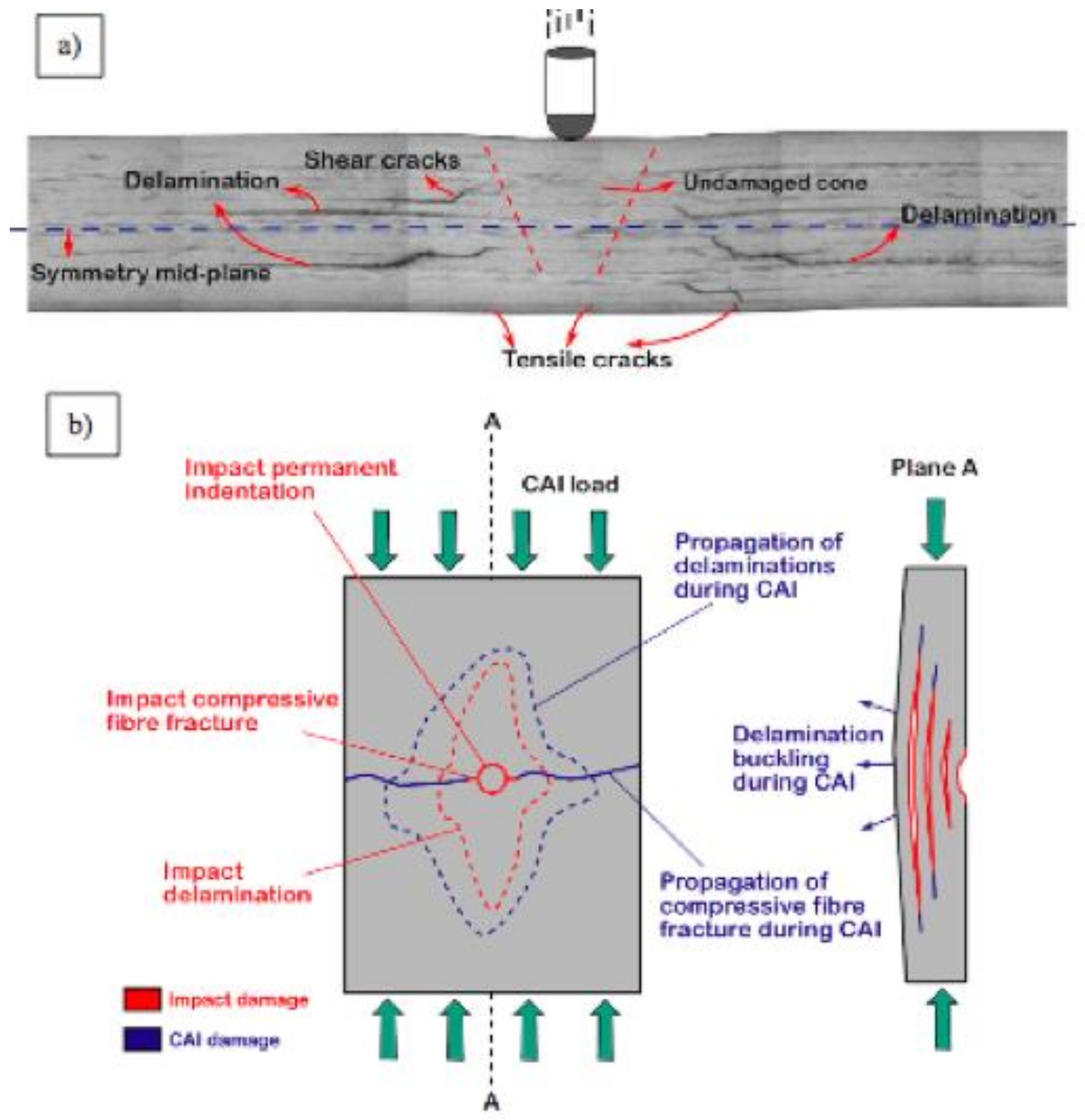
The Achilles heel of composite structures is the loss of properties as a consequence of local impacts, and particularly the loss of compressive strength, which may be reduced by 50% compared to the pristine structure. This process is illustrated in Figure 3. To make things even worse, these impacts do not leave any noticeable mark on the external surface and are known as barely visible impact damage (BVID); they cause large internal delaminations at every change of ply orientation [43]. These impacts may happen, for example, as a consequence of hailstones that hit the external aircraft surface during the take-off and landing flight phases, meaning it cannot be considered a rare event (at a speed of 100 m/s, an ice ball 10 mm in diameter with a mass of 8 g is equivalent to an impact energy of 40 J, which would cause a severe dent within a 2 mm thick aluminium surface).
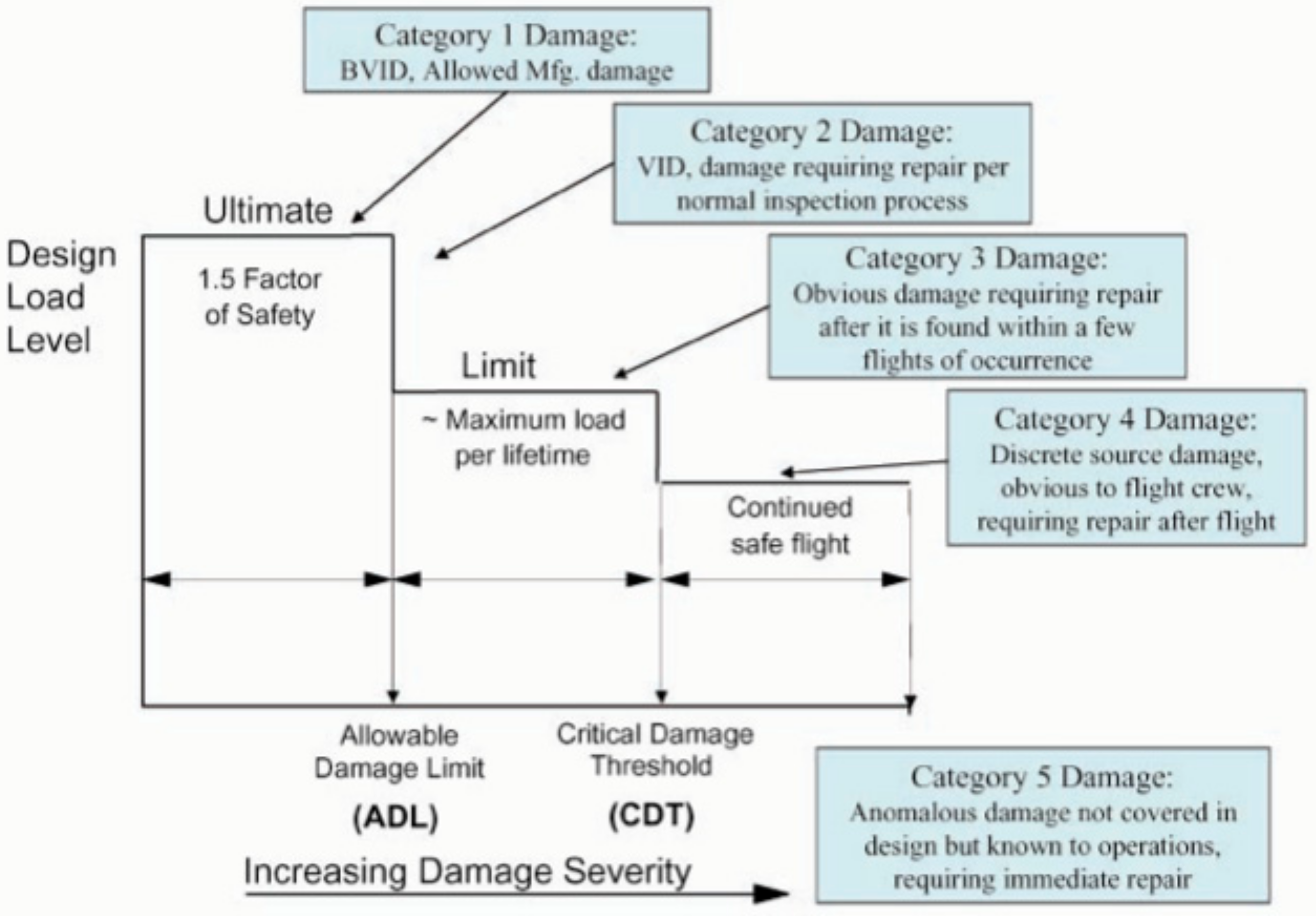
This is not the only damage that composite structures must withstand during their lifetime. As requested by the Federal Aviation Authorities (FAA) [44], the structure must be able to continue in flight-safe conditions even with stronger impacts (such as a bird weighting 2 kg hitting against the wing leading edges) which cause clearly visible damage above the critical damage threshold (CDT) (Figure 4). There are also some intermediate cases which are less severe but which have a higher probability of occurrence like a lightning strike, which would cause visible damage to the laminate surface (VID or Visible Impact Damage). As these damages may happen during flight time, the aircraft structure must be designed to keep flying until landing, even after damage and under the worst flying conditions, such as severe gusts or landing on a wheel only (all these cases are considered under design limit loads). The SHM system cannot do anything to alleviate this requirement, which is taken into account by selecting appropriate allowable values for the material properties. The SHM system helps by detecting any damage near and above the allowable damage limit (ADL), because the damage area will grow by fatigue loads and need to be repaired as soon as it is detected.
For non-aeronautic composite structures, like wind turbine blades, there are similar requirements; the hitting of big birds against the blade tip is not a low probability event.
The objective of SHM is to inform about the occurrence and extension of these damages, particularly for BVIDs, so the real condition of the structure can be better ascertained and a prognosis of residual strength can be performed.
5. Recent Advances on SHM Techniques and Standing Issues
We have restricted this discussion to approximately the last six years of published works. It was mentioned at the beginning of the article that SHM consists of sensors and algorithms, so it is worth considering both aspects and their limitations.
Sensors, particularly PZT and fiber optic sensors, have reached an adequate level of development; currently they are well understood, and no main changes to them have happened during the last ten years. In both cases, a wide range of equipment to acquire data from these sensors already exists in the market. V. Giurgiutiu’s book [45] probably contains all the information required by practitioners to work with PZT, both theoretically and experimentally. Concerning fiber optic sensors, fiber Bragg gratings (FBGs) as point strain sensors have been fully characterized, and the only big innovations have been improvements in sensitivity and working frequency to capture the strains caused by elastic waves and allow FBG usage as an alternative to PZT for acoustic emission, or within hybrid PZT-FBG systems. Even so, FBGs have not reached the same level of sensitivity as PZT, but their benefits of lower weight and easier connections make them an interesting alternative.
Fiber optic distributed sensing, which obtains strains all along an optical fiber, was announced in 1999, and the technology for it was developed over the following decade; now useful applications are currently performed at the industrial level, particularly in the field of large structural tests [46].
The main progress for SHM has come from advances in algorithms by taking the high data flow coming from sensors and converting it into a damage index after filtering out signals from environmental disturbances, operational conditions, and noise. It is worth mentioning that temperature changes are particularly disturbing, both for PZTs and for fiber optic sensors, and there is always a need to compensate for their effects.
Algorithms may be classified into two main groups, namely, model-based and data-driven approaches. For the model-based approach, a mathematical model based on physical laws is built for the structure (either Finite Element Models (FEM) or similar); damage will be a local change at an unknown place that changes the response of the structure, which has to be identified as an inverse problem. It is the most classical approach, and is still widely used in vibration and guided waves methods.
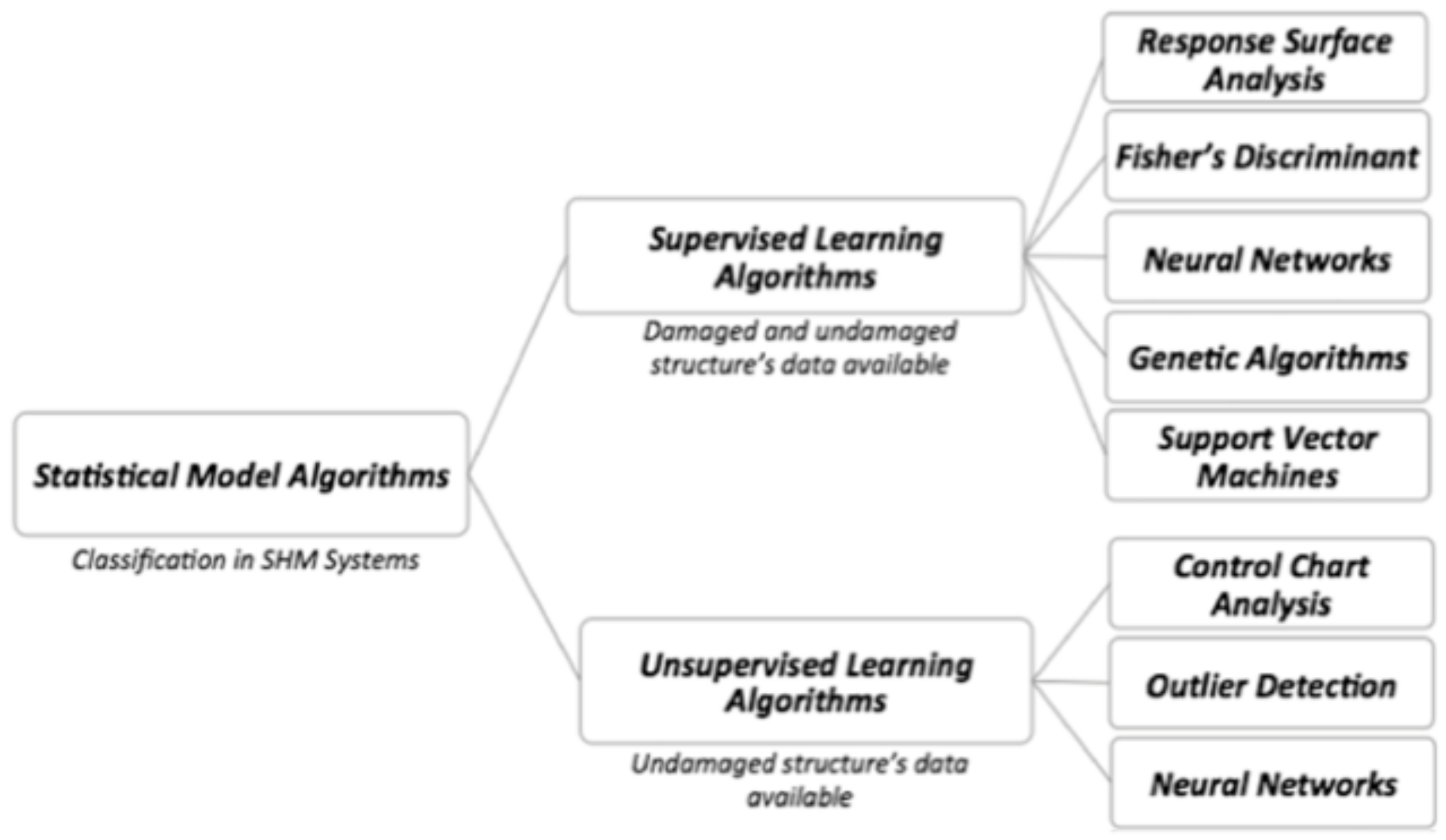
Data driven algorithms, also called pattern-recognition, do not need any understanding of the physics of the problem (though physics help to define good features or damage indicators) and only need to obtain a large collection of data from the structure, both for the pristine and for the presumably damaged structure. There are a variety of algorithms used to identify differences in the two data sets, algorithms which are globally included as “machine learning”. In Figure 5, obtained from [47], a list, though incomplete, of available algorithms is given. A wider and more detailed discussion can be found in [48,49], which are two fundamental texts for all people working on SHM.
Big Data will influence progress in the near future; in a recent review article, the authors conclude that [50] “it is possible to collect more data and information at a low cost, and it will lead to novel theories on structural health diagnosis and prognosis”.
Developers may find helpful the usage of software tools already available. The most popular is SHMTools, which is freely available through LANL/UCSD. Another example of this kind of tool is the “Object-oriented MATLAB toolbox for structural health monitoring” from Aalborg University.
5.1. Vibration Methods
Vibration methods are the kind of technique most widely used for civil engineering applications. They are also known as modal analysis, and their approach is similar to structural identification. They are commonly used to refine the finite element model of structures with experimental vibration data. When applied to damage detection, where the location of a local stiffness drop caused by the damage has to be sought, these methods have low resolution, so they are only suited to the identification of large cracks, which may change significantly the first frequencies and modal shapes. A simple calculation indicates that for an aluminium cantilever beam, a crack at its root which cuts 10% of the transversal section drops the first natural frequency by less than 1%, similar to the change produced by a small increment of temperature as consequence of the change in length due to thermal expansion. For numerical exercises the procedure works, but experimentally it is jeopardized by uncertainties, natural disturbances, and measurement errors.
5.2. Strain-Based Methods
Three papers [54,55,56] summarize quite well the state of the art for this approach. The first important comment is that the global strain field changes very little with the occurrence of a local crack, and is only noticeable at the crack tip. The second comment is that fiber optic sensors, i.e., either point sensors like FBGs or line-distributed sensors, are just strain and temperature sensors; hence, if the damage does not change the strain at the sensor position, it will not be detected.
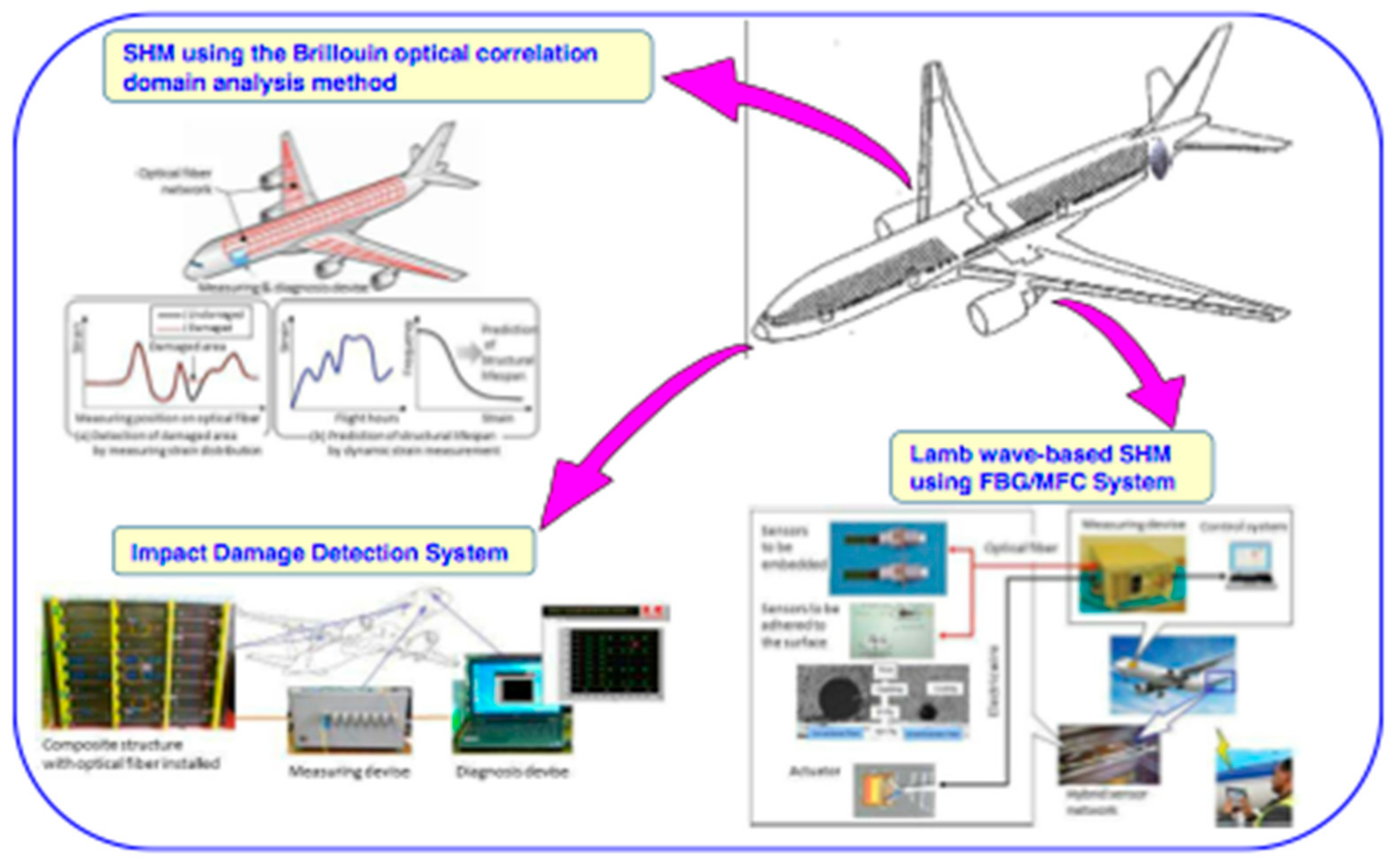
Figure 6, obtained from [57], illustrates three of the four existing approaches for damage detection with fiber optic sensors (FOS). Two of these approaches consist of using FBGs as acoustic sensors, similarly to piezoelectric wafers, either to locate impacts or for a hybrid PZT-FOS system. The approach located in the upper part of the figure requires the usage of distributed sensors for detecting residual strains caused by the damage, in case the optical fiber is located near there. Another procedure, called strain mapping, consists of detecting the changes in the strain field, which are caused by local loss of stiffness and consequent strain redistribution. Of course, in this latter case, damage does not need to happen near the optical fiber, but the structure needs to be submitted to external loads. A detailed explanation of these approaches can be found in Chapter 6 of the book “Structural Health Monitoring for Advanced Composite Structures” [58].
5.3. Guided Waves
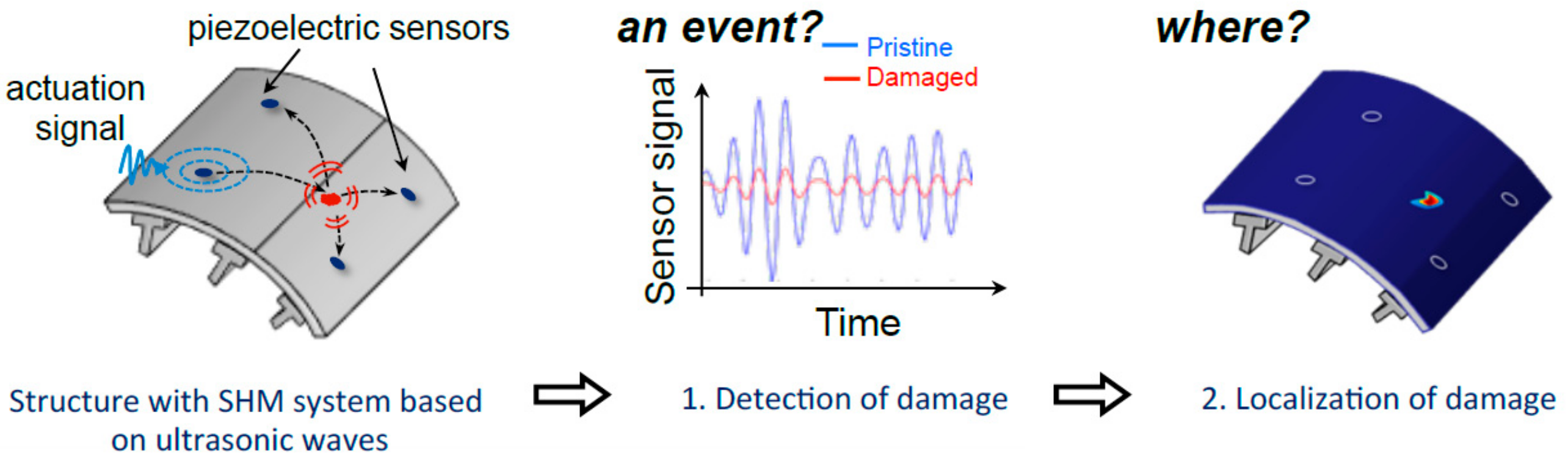
Guided waves is the most active field of research in SHM for aeronautics because it has the potential to detect very small sized damages, as requested by the aircraft industry. The principle is simple, as sketched in Figure 7: a PZT bonded/embedded into the structure launches a short ultrasonic pulse (the frequency used is a few hundred KHz) which propagates by the plate as an elastic wave, and the pulse is received, though very distorted, by other PZTs. The received signals are stored and compared to signals received later during the lifetime of the structure. Any new signal distortion must be due to some structural change in the path between the emitter-receiver PZTs. The concept works quite well in flat laminates, and small delaminations caused by an impact can be detected and even located. The technique also works very well for cylindrical tubes [4]. The difficulties grow when applying the concept to real structures with boundaries, stiffeners, and thickness changes. The elastic waves behave as any other waves, with reflection/refraction occurring at every interface, which complicates the received signals [59]. Additionally, thickness changes promote a mode conversion, and all modes are dispersive, traveling at different speeds (Lamb waves are a special type of guided waves which propagate along flat plates of uniform thickness, the only type of guided waves which have an analytical solution). Consequently, the signal acquisition and evaluation are much more difficult. Temperature and operational loads also introduce distortion to the received signals [60]. A lot of efforts are currently devoted to modeling wave propagation and interaction with defects for structures with increasing geometrical complexity, like stiffened structures [58,61,62].
5.4. Acoustic Emission
Acoustic emission (AE) is mostly used as an NDT procedure when operators locate and move the AE probes on the surface of the specimen being tested, but it works also as SHM when sensors are permanently attached to the structure and the data acquisition system is kept with the structure during operation. Usually PZT wafers (PWAS) are used for this case because they are less bulky and costly than standard probes, even if they are less sensitive. It has been identified that the signal/noise ratio is a critical issue, so a preamplifier located as near as possible to the sensor is a real constraint.
AE is a passive technique. The elastic wave to be captured by the sensor has to be produced by a growing crack, liberating energy. After this, the response and issues are very similar to those of the guided waves methods: waves reflect, distort, and dampen while traveling from the source. Data processing algorithms are different; while guided waves is mainly an active method, meaning the signals launched by the emitter are controlled and always the same shape, AE signals are always short bursts and the information is contained in the frequency, intensity, and duration. Reference [64] offers a recent review of more than 200 papers on AE; attention is paid to the signal attenuation in metallic and composite structures, a key factor with which to fix the distance source detector. Reference [65] provides a good discussion on experimental results obtained with PZT wafers, both for guided waves and for AE.
5.5. Carbon Nanotube-Doped Resins
Since the first paper on carbon nanotubes (CNT) was published by Iijima in 1991, the number of articles and applications of CNT has continuously increased, offering new and astonishing possibilities for advanced research and development. Theoretical studies demonstrate CNT composites would outperform mechanical properties of graphite fiber composites; unfortunately, they cannot be used to manufacture large structures. CNT have been added to resins to improve their interlaminar properties, with unequal success. They have also found applications as electronic devices, and above all, as sensors, either as chemical, biological, or mechanical sensors [66]. Restricting the discussion to strain and damage sensors, their positive aspects are their high sensitivity and their easiness to be adapted to whatever shape the structure is; they are truly distributed sensors and may cover large areas without complexity. Different fabrication procedures are used to build the sensor on the laminate, from mixing a dispersion of CNT with the uncured resin, to growing carbon nanotubes on glass fibers by Chemical Vapor Deposition (CVD), to preparing an ink to be applied onto the prepreg or adhesive films. The properties of sensors are strongly linked to the manufacturing route, the CNT percentage, and the quality of the dispersion. Reproducibility is still a main issue [67], with difficulties occurring in obtaining reliable results being demonstrated in a recent article [68]; strain measurements during cyclic loads in a pressure vessel show an inconsistent response, and damage initiation can sometimes be identified as a strong change in the resistance, but the magnitude cannot be correlated to the position or extent of the damage. Electrical impedance tomography, or imaging the internal impedance of a body from surface electrode measurements, is a technique already in use in medicine but is still in early development for SHM and is known as “sensitive skins” [69].
6. Probability of Detection
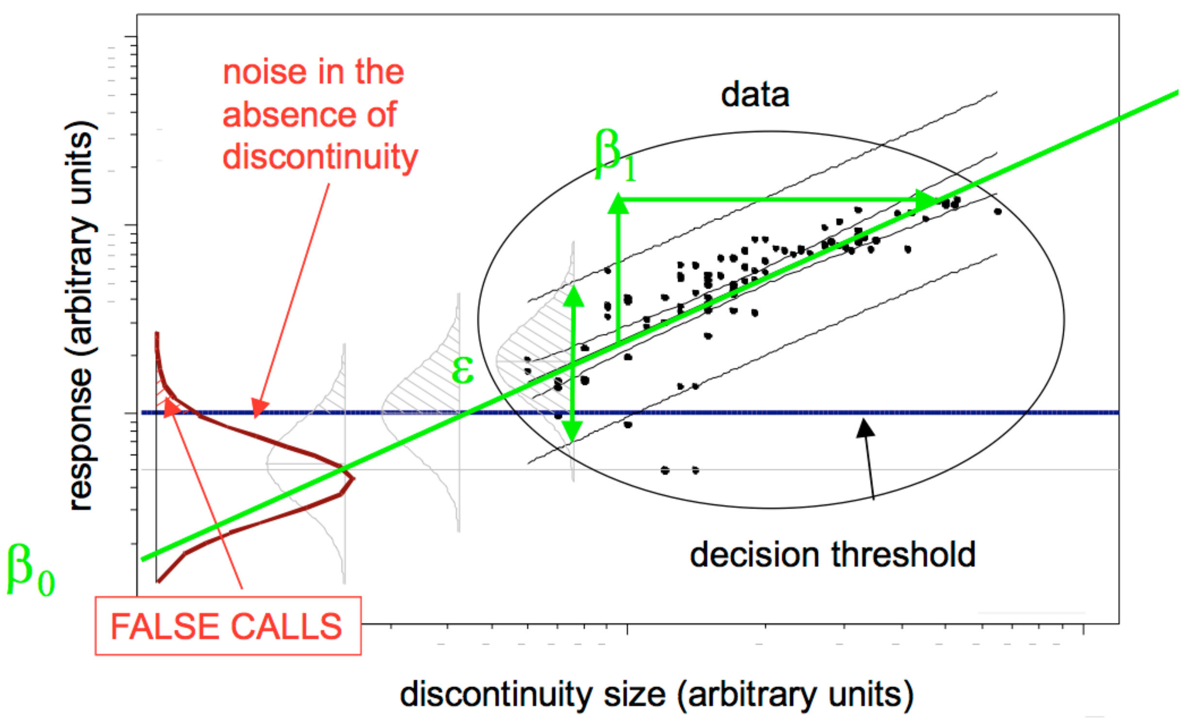
Conventional non-destructive evaluation (NDE) methods have been widely used since WWII, but it was in 1969 when NASA decided to quantify the reliability of these used methods by calculating, after repetitive inspections of flawed specimens, what the probability was that a crack of a given size could go undetected after a given inspection method under a defined inspection procedure. This information was needed in order to apply damage tolerance criteria to the design of structures by quantifying what the largest crack size was that could be missed during an inspection. Additionally, this allows for a comparison among the different NDE methods. There are many parameters, or uncertainties, that influence the detection capability, including surface roughness, operators, probes, flaw shape, orientation, depth, and even temperature; hence, obtaining a probability of detection (POD) curve requires careful experiment design with many samples. After this, and with an established procedure for analysis of the results, the confidence level (CL) is obtained. Finally, a commonly used number a90/95 can be given, meaning that crack sizes larger than a90/95 will be detected with 90% probability and with 95% confidence. Later on, these procedures evolved with the introduction of model-assisted probability of detection (MAPOD), which reduces the experimental tasks by modeling the response to the inspection method of the flawed material. The document MIL-HDBK-1823A was produced in 2009 [70], and it has been accepted as the standard ruling works related to POD for every NDE technique. Figure 8 is a graphical representation of the MIL-HDBK-1823 model, indicating data dispersion and the fitting to a linear regression analysis.
It is clear that in order to demonstrate the reliability of SHM systems, a similar approach must be conducted. As stated in [71], “The successful deployment of systems for health monitoring of structures depends on appropriate verification and validation (V&V) of these SHM systems. The V&V method must explicitly evaluate all aspects of the SHM system that can affect its capability to detect, localize, or characterize damage. Moreover, it must evaluate the effects that usage and environmental conditions have on these capabilities over time. For damage detection, this necessarily results in the need for a POD determination.”
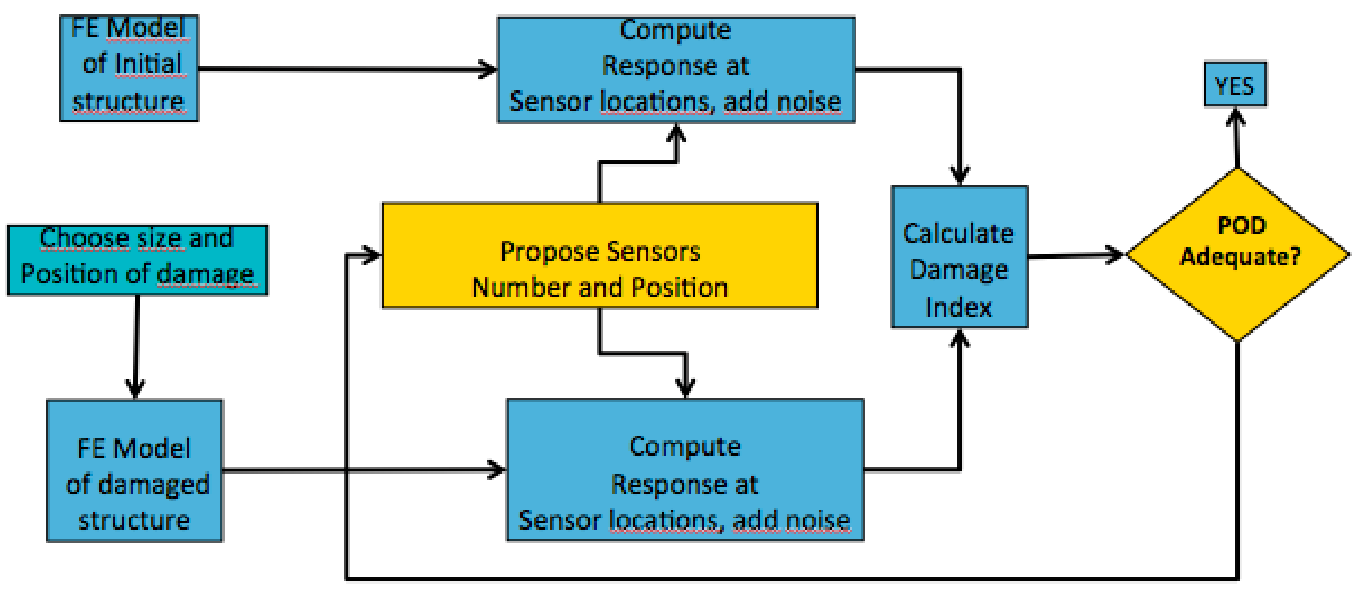
As stated in [63], which was one of the first articles to apply this methodology, NDE methods include the uncertainty of the operator’s ability, but the probe can be located exactly over the damage at its optimal position; for SHM systems the main difficulty comes from the fact that sensors have fixed positions while cracks may occur anywhere, and the response will change with the distance sensor damage, besides other factors, meaning the number of experiments with which to draw a POD curve may be prohibitively large. In [63] they ran a few experiments to demonstrate the feasibility, but clearly the support of a numerical simulation is required. Models for guided waves are already available, and recently a model (Figure 9) has been proposed for fiber optic SHM systems [72].
7. Conclusions
The benefits of implementing SHM techniques on existing and new structures have been widely highlighted and recognized; a proof of it can be seen in the large number of active research projects. At first glance, it may be difficult to understand why “condition monitoring”, or SHM for rotating machinery, has reached an industrial level, with many companies offering commercial products and services, while for static structures the business case is still not as favourable. Some reasons that explain this delay have been pointed out in [4]; main point is that research needs to focus on realistic structures, as some technologies and models that work on flat uniform plates cannot be translated to real structures or are very difficult to apply.
A few industrial applications are leading the way. For example, [73] describes an SHM system used for airworthiness assessment of the entire Israel Aerospace Industries HALE UAV fleet which is based on distributed strain sensing with embedded optical fibers.
A second point to consider is the size and kind of damage that needs to be detected. A lot of effort has been directed at detecting small delaminations, competing with the most advanced NDT procedures, while aircraft airworthiness requirements allow for much bigger sizes at the threshold among BVID and VID. If we consider other large composite structures, like wind turbine blades or unmanned aircraft vehicles, without risking lives, the requirements for detectable damage are even larger, as far as it can be reliably detected.
Reliability is the key question, and can only be demonstrated through a POD analysis. Attention has only been paid to this issue over the last ten years, but now it is a growing trend. Simulation of SHM systems is needed in order to reduce the number of experiments.
There is still always space for breakthrough concepts and for ideas that do not evolve from existing knowledge but which propose a radical new solution. This was the case when K. Hill proposed and demonstrated in 1976 the concept of FBG, which completely changed the world of fiber optic sensors, something which may happen again anytime. As an example, [74] has proposed a new kind of sensor for use with nonlinear elastic wave spectroscopy (NEWS), which may be a scientific curiosity or may open up more efficient ways to undertake damage detection.
Author Contributions
Funding
This work was partially sponsored by the DACOMAT project. The DACOMAT project has received funding from the European Union’s Horizon 2020 research and innovation programme under GA No. 761072.
Conflicts of Interest
The authors declare no conflict of interest.
References
- Askaripour, K.; Zak, A. A Survey of Scrutinizing Delaminated Composites via Various Categories of Sensing Apparatus. J. Compos. Sci. 2019, 3, 95. [Google Scholar] [CrossRef] [Green Version]
- Coronado, D.; Fischer, K. Condition Monitoring of Wind Turbines: State of the Art, User Experience and Recommendations; Final Report VGB-Nr.383; Fraunhofer IWES: Bremerhaven, Germany, 2015. [Google Scholar]
- Roach, D. Does the Maturity of Structural Health Monitoring Technology match user Readiness? In Proceedings of the International Workshop on SHM, Stanford, CA, USA, 13–15 September 2011. [Google Scholar]
- Cawley, P. Structural health monitoring: Closing the gap between research and industrial deployment. Struct. Health Monit. 2018, 17, 1225–1244. [Google Scholar] [CrossRef] [Green Version]
- Farrar, C.R.; Doebling, S.W.; Nix, D.A. Vibration-based structural damage identification. Philos. Trans. Royal Soc. A Math. Phys. Eng. Sci. 2001, 359, 131–149. [Google Scholar] [CrossRef]
- Yan, A.-M.; Kerschen, G.; De Boe, P.; Golinval, J.-C. Structural damage diagnosis under varying environmental conditions—Part I: A linear analysis. Mech. Syst. Signal Process. 2005, 19, 847–864. [Google Scholar] [CrossRef]
- Sampaio, R.P.C.; Maia, N.M.M.; Silva, J.M.M. Damage detection using the frequency-response-function curvature method. J. Sound Vib. 1999, 226, 1029–1042. [Google Scholar] [CrossRef]
- Montalvao, D.; Maia, N.M.; Ribeiro, A.M. A review of vibration-based structural health monitoring with special emphasis on composite materials. Shock Vib. Digest 2006, 38, 295–324. [Google Scholar] [CrossRef]
- Fan, W.; Qiao, P. Vibration-based damage identification methods: A review and comparative study. Struct. Health Monit. 2011, 10, 83–111. [Google Scholar] [CrossRef]
- LeBlanc, M.; Huang, S.Y.; Ohn, M.; Measures, R.M.; Güemes, A.; Othonos, A. Distributed strain measurement based on a fiber Bragg grating and its reflection spectrum analysis. Opt. Lett. 1996, 21, 1405–1407. [Google Scholar] [CrossRef]
- Güemes, A.; Diaz-Carrillo, S.; Menendez, J.M. Measurement of strain distribution in bonded joints by fiber Bragg gratings. Proc. SPIE 1998, 3330, 264–271. [Google Scholar]
- Güemes, A.; Menéndez, J.M. Response of Bragg grating fiber-optic sensors when embedded in composite laminates. Compos. Sci. Technol. 2002, 62, 959–966. [Google Scholar] [CrossRef]
- Majumder, M.; Gangopadhyay, T.K.; Chakraborty, A.K.; Dasgupta, K.; Bhattacharya, D.K. Fibre Bragg gratings in structural health monitoring-Present status and applications. Sens. Actuators A Phys. 2008, 147, 150–164. [Google Scholar] [CrossRef]
- López-Higuera, J.M. (Ed.) Handbook of Optical Fibre Sensing Technology; Wiley: Hoboken, NJ, USA, 2002. [Google Scholar]
- Guo, H.; Xiao, G.; Mrad, N.; Yao, J. Fiber optic sensors for structural health monitoring of air platforms. Sensors 2011, 11, 3687–3705. [Google Scholar] [CrossRef]
- Luyckx, G.; Voet, E.; Lammens, N.; Degrieck, J. Strain measurements of composite laminates with embedded fibre bragg gratings: Criticism and opportunities for research. Sensors 2011, 11, 384–408. [Google Scholar] [CrossRef] [PubMed] [Green Version]
- Sierra-Pérez, J.; Güemes, A.; Mujica, L.E. Damage detection by using FBGs and strain field pattern recognition techniques. Smart Mater. Struct. 2013, 22, 025011. [Google Scholar] [CrossRef] [Green Version]
- Croxford, A.J.; Wilcox, P.D.; Drinkwater, B.W.; Konstantinidis, G. Strategies for guided-wave structural health monitoring. Proc. R. Soc. A Math. Phys. Eng. Sci. 2007, 463, 2961–2981. [Google Scholar] [CrossRef]
- Raghavan, A.; Cesnik, C.E.S. Review of guided-wave structural health monitoring. Shock Vib. Digest 2007, 39, 91–114. [Google Scholar] [CrossRef]
- Staszewski, W.J.; Mahzan, S.; Traynor, R. Health monitoring of aerospace composite structures—Active and passive approach. Compos. Sci. Technol. 2009, 69, 1678–1685. [Google Scholar] [CrossRef]
- Rose, J.L. Ultrasonic Waves in Solid Media; Cambridge University Press: Cambridge, UK, 2004. [Google Scholar]
- Ostachowicz, W.; Kusela, P.; Krawczuk, M.; Zak, A. Guided Waves in Structures for SHM: The Time-Domain Spectral Element, Method; John Wiley & Sons, Ltd.: London, UK, 2012. [Google Scholar]
- Ihn, J.-B.; Chang, F.-K. Pitch-catch active sensing methods in structural health monitoring for aircraft structures. Struct. Health Monit. 2008, 7, 5–19. [Google Scholar] [CrossRef]
- Wang, C.H.; Rose, J.T.; Chang, F.-K. A synthetic time-reversal imaging method for structural health monitoring. Smart Mater. Struct. 2004, 13, 415. [Google Scholar] [CrossRef]
- Ciang, C.-C.; Lee, J.-R.; Bang, H.-J. Structural health monitoring for a wind turbine system: A review of damage detection methods. Meas. Sci. Technol. 2008, 19, 122001. [Google Scholar] [CrossRef] [Green Version]
- Giurgiutiu, V.; Santoni-Bottai, G. Structural health monitoring of composite structures with piezoelectric-wafer active sensors. AIAA J. 2011, 49, 565–581. [Google Scholar] [CrossRef] [Green Version]
- Park, H.W.; Sohn, H.; Law, K.H.; Farrar, C.R. Time reversal active sensing for health monitoring of a composite plate. J. Sound Vib. 2007, 302, 50–66. [Google Scholar] [CrossRef]
- Giurgiutiu, V.; Soutis, C. Enhanced composites integrity through structural health monitoring. Appl. Compos. Mater. 2012, 19, 813–829. [Google Scholar] [CrossRef]
- Ciampa, F.; Meo, M. A new algorithm for acoustic emission localization and flexural group velocity determination in anisotropic structures. Compos. Part A Appl. Sci. Manuf. 2010, 41, 1777–1786. [Google Scholar] [CrossRef]
- De Oliveira, R.; Marques, A.T. Health monitoring of FRP using acoustic emission and artificial neural networks. Comput. Struct. 2008, 86, 367–373. [Google Scholar] [CrossRef]
- Giurgiutiu, V.; Bao, J. Embedded-ultrasonics structural radar for in situ structural health monitoring of thin-wall structures. Struct. Health Monit. 2004, 3, 121–140. [Google Scholar] [CrossRef] [Green Version]
- Yoo, B.; Purekar, A.S.; Zhang, Y.; Pines, D.J. Piezoelectric-paint-based two-dimensional phased sensor arrays for structural health monitoring of thin panels. Smart Mater. Struct. 2010, 19, 075017. [Google Scholar] [CrossRef]
- Roach, D. Real time crack detection using mountable comparative vacuum monitoring sensors. Smart Struct. Syst. 2009, 5, 317–328. [Google Scholar] [CrossRef]
- Stehmeier, H.; Speckmann, H. Comparative vacuum monitoring (CVM). In Proceedings of the 2nd European Workshop on Structural Health Monitoring, Munich, Germany, 7–9 July 2004. [Google Scholar]
- Giurgiutiu, V.; Rogers, C.A. Recent advancements in the electromechanical (E/M) impedance method for structural health monitoring and NDE. In Proceedings of the 5th Annual International Symposium on Smart Structures and Materials, San Diego, CA, USA, 27 July 1998; Volume 3329, pp. 536–547. [Google Scholar]
- Bhalla, S.; Gupta, A.; Bansal, S.; Garg, T. Ultra low-cost adaptations of electro-mechanical impedance technique for structural health monitoring. J. Intell. Mater. Syst. Struct. 2009, 20, 991–999. [Google Scholar] [CrossRef]
- Kang, I.; Schulz, M.J.; Kim, J.H.; Shanov, V.; Shi, D. A carbon nanotube strain sensor for structural health monitoring. Smart Mater. Struct. 2006, 15, 737–748. [Google Scholar] [CrossRef]
- Loh, K.J.; Hou, T.-C.; Lynch, J.P.; Kotov, N.A. Carbon nanotube sensing skins for spatial strain and impact damage identification. J. Nondestruct. Eval. 2009, 28, 9–25. [Google Scholar] [CrossRef]
- Goldfine, N.; Zilberstein, V.; Washabaugh, A.; Schlicker, D.; Shay, I.; Grundy, D. Eddy current sensor networks for aircraft fatigue monitoring. Mater. Eval. 2003, 61, 852–859. [Google Scholar]
- Speckmann, H.; Henrich, R. Structural health monitoring (SHM)–overview on technologies under development. In Proceedings of the World Conference on NDT, Montreal, QC, Canada, 30 August–3 September 2004. [Google Scholar]
- Boller, C.; Chang, F.K.; Fujino, Y. (Eds.) Encyclopedia of Structural Health Monitoring; Wiley: New York, NY, USA, 2009. [Google Scholar]
- Ostachowicz, W.; Güemes, A. (Eds.) New Trends in Structural Health Monitoring; Springer: Cham, Switzerland, 2013. [Google Scholar]
- Ostré, B.; Bouvet, C.; Minot, C.; Aboissière, J. Experimental analysis of CFRP laminates subjected to compression after edge impact. Compos. Struct. 2016, 152, 767–778. [Google Scholar] [CrossRef] [Green Version]
- FAA Advisory Circular AC nb 20-107B Composite Aircraft structures (9 August 2009). Available online: www.faa.gov/documentLibrary/media/Advisory_Circular/AC20-107B.pdf (accessed on 23 January 2020).
- Giurgiutiu, V. Structural Health Monitoring with Piezoelectric Wafer Active Sensors, 2nd ed.; Academic Press: New York, NY, USA, 2014. [Google Scholar]
- Güemes, A.; Fernández-López, A.; Soller, B. Optical fiber distributed sensing - physical principles and applications. Struct. Health Monit. 2010, 9, 233–245. [Google Scholar] [CrossRef]
- Martinez-Luengo, M.; Kolios, A.; Wang, L. Structural health monitoring of offshore wind turbines: A review through the Statistical Pattern Recognition Paradigm. Renew. Sustain. Energy Rev. 2016, 64, 91–105. [Google Scholar] [CrossRef] [Green Version]
- Worden, K.; Staszewski, W.J.; Hensman, J.J. Natural computing for mechanical systems research: A tutorial overview. Mech. Syst. Signal Process. 2011, 25, 4–111. [Google Scholar] [CrossRef]
- Farrar, C.R.; Worden, K. Structural Health Monitoring: A Machine Learning Perspective; John Wiley & Sons, Ltd.: London, UK, 2013; ISBN 9781119994336. [Google Scholar]
- Bao, Y.; Chen, Z.; Wei, S.; Xu, Y.; Tang, Z.; Li, H. The State of the Art of Data Science and Engineering in Structural Health Monitoring. Engineering 2019, 5, 234–242. [Google Scholar] [CrossRef]
- Goyal, D.; Pabla, B.S. The vibration monitoring methods and signal processing techniques for structural health monitoring: A review. Arch. Comput. Methods Eng. 2016, 23, 585–594. [Google Scholar] [CrossRef]
- Amafabia, D.M.; Montalvão, D.; David-West, O.; Haritos, G. A Review of Structural Health Monitoring Techniques as Applied to Composite Structures. Struct. Durab. Health Monit. 2017, 11, 91–147. [Google Scholar]
- Gomes, G.F.; Mendéz, Y.A.D.; Da Silva Lopes Alexandrino, P.; Da Cunha, S.S., Jr.; Ancelotti, A.C., Jr. The use of intelligent computational tools for damage detection and identification with an emphasis on composites—A review. Compos. Struct. 2018, 196, 44–54. [Google Scholar] [CrossRef]
- Di Sante, R. Fibre optic sensors for structural health monitoring of aircraft composite structures: Recent advances and applications. Sensors 2015, 15, 18666–18713. [Google Scholar] [CrossRef] [PubMed]
- Kinet, D.; Mégret, P.; Goossen, K.W.; Qiu, L.; Heider, D.; Caucheteur, C. Fiber Bragg grating sensors toward structural health monitoring in composite materials: Challenges and solutions. Sensors 2014, 14, 7394–7419. [Google Scholar] [CrossRef] [PubMed]
- Güemes, A.; Fernández-López, A.; Díaz-Maroto, P.F.; Lozano, A.; Sierra-Perez, J. Structural health monitoring in composite structures by fiber-optic sensors. Sensors 2018, 18, 1094. [Google Scholar] [CrossRef] [PubMed] [Green Version]
- Isoe, A.; Kojima, H.; Enomoto, K.; Takeda, N. Outline of the Japanese National Project on Structural Health Monitoring System for Aircraft Composite Structures and JASTAC Project. In Proceedings of the 8th EWSHM 2016, Bilbao, Spain, 5–8 July 2016. [Google Scholar]
- Aliabadi, M.H.F.; Sharif Khodeai, Z. Structural Health Monitoring for Advanced Composite Structures; World Scientific Publishing Ltd.: London, UK, 2018. [Google Scholar]
- Memmolo, V.; Monaco, E.; Boffa, N.D.; Maio, L.; Ricci, F. Guided wave propagation and scattering for structural health monitoring of stiffened composites. Compos. Struct. 2018, 184, 568–580. [Google Scholar] [CrossRef]
- Salmanpour, M.S.; Sharif Khodaei, Z.; Aliabadi, M.H. Guided wave temperature correction methods in structural health monitoring. J. Intell. Mater. Syst. Struct. 2017, 28, 604–618. [Google Scholar] [CrossRef] [Green Version]
- Mitra, M.; Gopalakrishnan, S. Guided wave based structural health monitoring: A review. Smart Mater. Struct. 2016, 25, 053001. [Google Scholar] [CrossRef]
- Miniaci, M.; Mazzotti, M.; Radzienski, M.; Kudela, P.; Kherraz, N.; Bosia, F.; Pugno, N.M.; Ostachowicz, W. Application of a laser-based time reversal algorithm for impact localization in a stiffened aluminium plate. Front. Mater. 2019, 6, 30. [Google Scholar] [CrossRef]
- Janapati, V.; Kopsaftopoulos, F.; Li, F.L.; Lee, S.; Chang, F.-K. Damage Detection Sensitivity Characterization of Acousto-Ultrasound-based SHM Techniques. Struct. Health Monit. 2016, 15, 143–161. [Google Scholar] [CrossRef]
- Ono, K. Review on structural health evaluation with acoustic emission. Appl. Sci. 2018, 8, 958. [Google Scholar] [CrossRef] [Green Version]
- Mei, H.; Haider, M.F.; Joseph, R.; Migot, A.; Giurgiutiu, V. Recent advances in piezoelectric wafer active sensors for structural health monitoring applications. Sensors 2019, 19, 383. [Google Scholar] [CrossRef] [Green Version]
- Zaporotskova, I.V.; Borozninaa, N.P.; Parkhomenkob, Y.N.; Kozhitovb, L.V. Carbon nanotubes: Sensor properties. A review. Mod. Electron. Mater. 2016, 2, 95–105. [Google Scholar] [CrossRef]
- Han, Z.; Bilotti, E.; Peijs, T. The use of carbon nanotubes for damage sensing and structural health monitoring in laminated composites: A review. Nanocomposites 2015, 1, 167–184. [Google Scholar]
- Xiao, B.; Yang, B.; Xuan, F.; Wan, Y.; Hu, C.; Jin, P.; Lei, H.; Xiang, Y.; Yang, K. In-Situ Monitoring of a Filament Wound Pressure Vessel by the MWCNT Sensor under Hydraulic Fatigue Cycling and Pressurization. Sensors 2019, 19, 1396. [Google Scholar] [CrossRef] [PubMed] [Green Version]
- Loyola, B.R.; La Saponara, V.; Loh, K.J.; Briggs, T.M.; O’Bryan, G.; Skinner, J.L. Spatial Sensing Using Electrical Impedance Tomography. IEEE Sens. J. 2013, 13, 2357. [Google Scholar] [CrossRef]
- MIL-HDBK 1823A, ‘Non-destructive Evaluation System Reliability Assessment’ (2009). Available online: http://www.statisticalengineering.com/mh1823/MIL-HDBK-1823A(2009).pdf (accessed on 23 January 2020).
- Aldrin, J.C.; Annis, C.; Sabbagh, H.A.; Lindgren, E.A. Best Practices for Evaluating the Capability of Nondestructive Evaluation (NDE) and Structural Health Monitoring (SHM) Techniques for Damage Characterization. AIP Conf. Proc. 2016, 1706, 200002. [Google Scholar] [CrossRef] [Green Version]
- Güemes, A.; Fernandez-Lopez, A.; Frovel, M.; Pintado, J.M.; Garcia-Ramirez, J.; Reyes, E. Experimental validation of a fiber-optic based SHM system. In Proceedings of the 7th Asian-Pacific Workshop on SHM, Hong Kong, China, 12–15 November 2018. [Google Scholar]
- Shapira, O.; Ben-Simon, U.; Bergman, A.; Shoham, S.; Glam, B.; Kressel, I.; Yehoshua, T.; Tur, M. Structural Health Monitoring of a UAV Fleet Using Fiber Optic Distributed Strain Sensing. In Proceedings of the IWSHM 2015, Stanford, CA, USA, 1–3 September 2015. [Google Scholar]
- Miniaci, M.; Gliozzi, A.; Morvan, B.; Krushynska, A.; Bosia, F.; Scalerandi, M.; Pugno, N. Proof of concept for an ultrasensitive technique to detect and localize sources of elastic nonlinearity using phononic crystals. Phys. Rev. Lett. 2017, 118, 214301. [Google Scholar] [CrossRef] [Green Version]
Figure 1.
Maintenance strategies with/without structural health monitoring (SHM).

Figure 2.
Typical defects/damages in composite laminates. From left to right, top to bottom: delamination with internal ply failures, external wrinkle, foreign object, internal and edge delaminations, internal wrinkle, distributed porosity, and debonding.
Figure 2.
Typical defects/damages in composite laminates. From left to right, top to bottom: delamination with internal ply failures, external wrinkle, foreign object, internal and edge delaminations, internal wrinkle, distributed porosity, and debonding.

Figure 3.
Impact damage and loss of compressive strength, (reproduced with permission from [43]). Legend Compression After Impact (CAI). (a) Internal damages caused inside a laminate by the impact of a foreign object (b) Loss of compressive strength as a consequence of these damages.
Figure 3.
Impact damage and loss of compressive strength, (reproduced with permission from [43]). Legend Compression After Impact (CAI). (a) Internal damages caused inside a laminate by the impact of a foreign object (b) Loss of compressive strength as a consequence of these damages.

Figure 4.
Design load levels versus damage severity as required by the Federal Aviation Authorities (FAA) (reproduced with permission from [44]).
Figure 4.
Design load levels versus damage severity as required by the Federal Aviation Authorities (FAA) (reproduced with permission from [44]).

Figure 5.
Classification of algorithms for SHM (reproduced with permission from [47]).
Figure 5.
Classification of algorithms for SHM (reproduced with permission from [47]).

Figure 6.
Damage detection alternatives with fiber optic sensors (reproduced with permission from [57]). Legend: Fiber Bragg Grating (FBG), Macro Fiber Composite (MFC).
Figure 6.
Damage detection alternatives with fiber optic sensors (reproduced with permission from [57]). Legend: Fiber Bragg Grating (FBG), Macro Fiber Composite (MFC).

Figure 7.
Diagram for damage detection with guided waves (reproduced with permission from [63]).
Figure 7.
Diagram for damage detection with guided waves (reproduced with permission from [63]).

Figure 8.
Damage index versus damage size (reproduced with permission from [70]).
Figure 8.
Damage index versus damage size (reproduced with permission from [70]).

Figure 9.
Algorithm used to calculate probability of detection (POD) from strain measurements (reproduced with permission from [72]).
Figure 9.
Algorithm used to calculate probability of detection (POD) from strain measurements (reproduced with permission from [72]).


Table 1.
Classification of Structural Health Monitoring (SHM) Technologies.
| Physical Principle | Techniques | Main Sensor Type | Range | Refs |
|---|---|---|---|---|
| Continuous Mechanics | Vibration methods | Accelerometers | Global local | [5,6,7,8,9] |
| Strain-based methods | Fiber optic sensors | Mid-range | [10,11,12,13,14,15,16,17] | |
| Elastic waves | Guided waves | PZT | Mid-range (m) | [18,19,20,21,22,23,24,25,26,27,28] |
| Acoustic emission | PZT, AE probes | Mid-range (m) | [29,30] | |
| Phased arrays | PZT | Mid-range (m) | [31,32] | |
| Fluid dynamics | Comparative vacuum monitoring (CVM) | Patch with microchannels | Local | [33,34] |
| Electricity and magnetism | Electromechanical impedance (EMI) | PZT | Local | [35,36] |
| Electrical impedance tomography | CNT-doped resins | Local | [37,38] | |
| Eddy currents | Eddy probes | Local | [39,40] |
© 2020 by the authors. Licensee MDPI, Basel, Switzerland. This article is an open access article distributed under the terms and conditions of the Creative Commons Attribution (CC BY) license (http://creativecommons.org/licenses/by/4.0/).
Share and Cite
MDPI and ACS Style
Güemes, A.; Fernandez-Lopez, A.; Pozo, A.R.; Sierra-Pérez, J. Structural Health Monitoring for Advanced Composite Structures: A Review. J. Compos. Sci. 2020, 4, 13. https://doi.org/10.3390/jcs4010013
AMA Style
Güemes A, Fernandez-Lopez A, Pozo AR, Sierra-Pérez J. Structural Health Monitoring for Advanced Composite Structures: A Review. Journal of Composites Science. 2020; 4(1):13. https://doi.org/10.3390/jcs4010013
Chicago/Turabian StyleGüemes, Alfredo, Antonio Fernandez-Lopez, Angel Renato Pozo, and Julián Sierra-Pérez. 2020. "Structural Health Monitoring for Advanced Composite Structures: A Review" Journal of Composites Science 4, no. 1: 13. https://doi.org/10.3390/jcs4010013