1. Introduction
The aviation industry has identified the accelerated development of active clearance control (ACC) systems as key to delivering the European Aviation Advisory Council’s 2020 targets of increased efficiency, reduced emissions and increased flight cycles [
1]. ACC reduces turbine tip leakage flow, irreversible mixing, diffusion and instabilities, which increases stage efficiency [
2] and lengthens engine service life—a considerable advantage given that a major engine overhaul can cost upwards of USD 1 M [
3]. High-pressure turbine (HPT) ACC has been shown to improve net specific fuel consumption (SFC) by 0.7% over non-HPT ACC engines [
4], with the potential to increase to >1% with further optimisation of the HPT ACC system [
5]. NOx and CO emissions are reduced by 10% and 16%, respectively, with the implementation of HPT ACC in short haul aircraft [
6].
2. Literature Review
The vast majority of turbine ACC systems in commercial aero-engines use an active thermal management approach [
3]. Air that is relatively cheap in terms of cycle efficiency is extracted from the bypass or compressor and impinged against the external side of the turbine casing in order to control turbine casing growth. Depending on the engine and flight-specific tip clearance profile, thermal response characteristics and operating point, HPT/LPT ACC air is either supplied from the fan duct (e.g., [
7]), or the compressor (e.g., [
4]). Turbine ACC systems are typically activated during cruise to reduce passive clearance (e.g., [
8]) but there is increased effort to develop fast-acting turbine ACC systems (< 5 s response time) to accommodate rapid rotor growth during take-off, reacceleration and sudden changes in operating conditions [
6].
A key parameter in the design of HPT and low-pressure turbine (LPT) ACC systems is the relative growth rate of the turbine casing and rotor disk, being an engine-specific function of component thermal masses, core/system aero-thermal fields, fixture locations and symmetric/asymmetric flight and engine loads [
3]. Pinch points, i.e., the periods of minimum tip clearance, traditionally occur at take-off, reacceleration and during sudden changes in operating conditions [
9], though some recent production engines experience pinch points at steady cruise due to rotor disks with reduced thermal capacity [
10].
The optimum active thermal ACC geometry varies from engine to engine, but the over-arching aero-thermal design philosophy for turbine ACC systems is basically the same; namely, to minimise the ACC air flow and time required to deliver the target casing temperature and turbine tip clearance. Setting the target tip clearance is a non-trivial balance between efficiency, reliability, emissions, flight cycles and complexity, so it is common to break the conjugate optimisation problem into simplified non-conjugate objectives for the ACC system:
- i.
Maximise the heat transfer coefficient (HTC) enhancement on the external casing generated by the impinging jets, for a given pressure drop within the ACC system.
- ii.
Generate circumferentially and axially uniform HTC for uniform tip clearance.
- iii.
Maximise the temperature difference between the impinging jet and the external side of the casing, to increase the rate of convective cooling for a given HTC.
These principles have driven the latest advances in impingement hole spacing [
8], hole shaping [
11] and separation distances [
12] in ACC manifolds. Overall performance may be further improved by adding model fidelity, e.g., asymmetric clearance effects (affecting the optimum circumferential HTC distribution), the non-linearity between HTC and pressure drop (such that the overall pressure ratio becomes an optimisable parameter), and conductive and radiative heat transfer [
13].
Equally important are capital and operating expenditure drivers on weight, manufacturability, maintenance, reliability (on and off design), material cost and size. The entire ACC system from offtake (start) to vent (finish) must be considered: thermal expansion joints, support structures, control valves, etc. Another, subtler driver in ACC design is the ease with which it can be optimised, because the sensitivity of design architecture to perturbations in operating and geometric boundary conditions is a good indication of the potential reliability of the system and influences engine development cost and schedule.
A topic that has not been investigated in the literature—and is the focus of this paper—is the optimum method for feeding fan/compressor air into the impingement manifold. There are two main feed architectures that are utilised in current production commercial aero-engines:
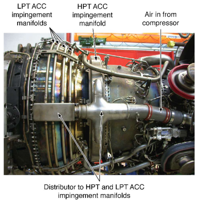
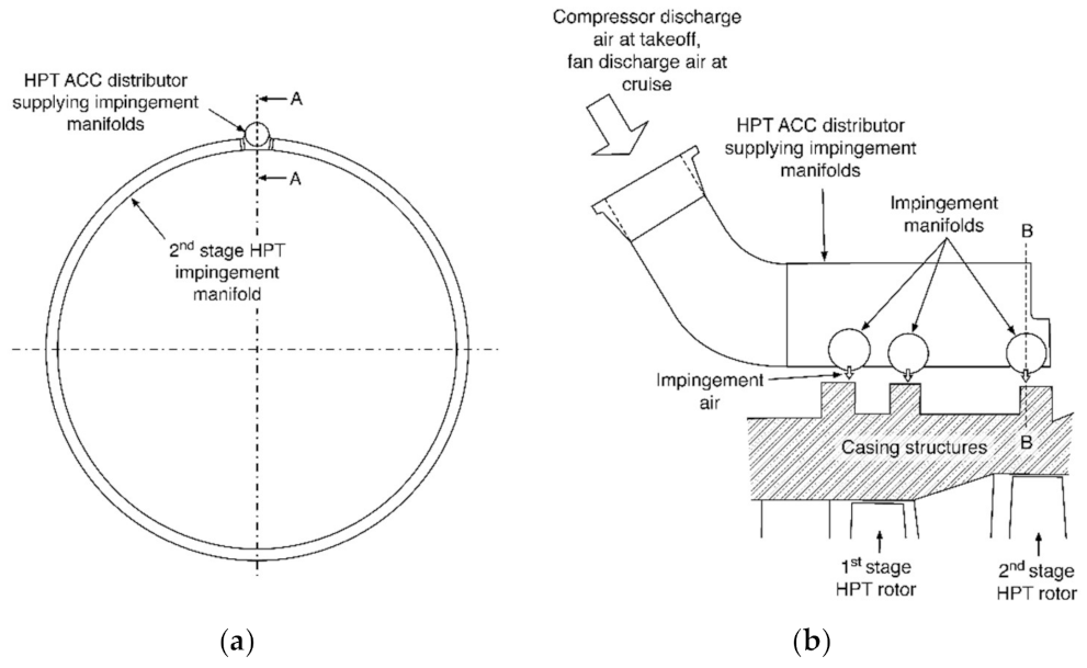
- 1.
Single-entry casing impingement manifolds. The casing impingement manifold is supplied at a single circumferential location via a collector box. The impingement manifold is either a single 360° annulus or two 180° sectors. Examples of single-entry casing impingement manifolds include the MTU aero-engine shown in
Figure 1, the GE CF6-6 architecture shown in
Figure 2 and the engine-scale experiments of Dann et al. [
14].
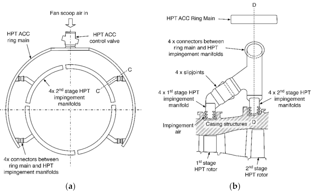
- 2.
Multiple-entry casing impingement manifolds. The casing impingement manifold is fed at multiple circumferential locations, typically four, from a secondary ring main, via connectors (also known as transfer boxes). The impingement manifold is split into annular sectors. The ring main is fed at a single circumferential location. An example of a multiple-entry casing impingement manifold is the NASA Energy Efficient Engine (E
3) architecture shown in
Figure 3.
While the driving design philosophy of the single-entry system is simplicity, the philosophy of the multiple-entry system is greater control, i.e., feed air more uniformly over the circumference of the impingement manifold.
3. Research Problem
In this paper, we examine using computational fluid dynamics (CFD) the relative performance of the single-entry system vs. the multiple-entry system. We depart from the previous literature in that we simulate the feed system (ring main, connectors, etc.) as well as the impingement manifold. The domain is fully annular. Consequently, the boundary conditions at the entry to the casing impingement manifolds are more realistic, as are the secondary flow features generated within the curved domain. The enhanced fidelity gives us the unique chance to make a fair back-to-back comparison between the single-entry and multiple-entry systems.
This is a timely discussion given the rapid development of novel engine architectures by aero-engine manufacturers and the sustained efforts to reduce emissions and increase SFC and flight cycles. As we will show, the system for supplying the casing impingement manifold has significant implications for the overall performance of the ACC system. Almost all the performance parameters discussed previously are influenced by the choice of the feed method: magnitude and uniformity of the HTC distribution, the temperature of the impinging jet, weight, manufacturability, complexity, size, ease of optimisation. The ease of optimisation involves the agility with which design changes can be conceptualized, implemented and manufactured within the context of civil aviation engine development programs. We will conclude that the single-entry system outperforms the multiple-entry system on almost all performance metrics.
4. Approach
In this paper, we investigate the effect of single-entry vs. multiple-entry feed on the performance of an HPT ACC system. The aero-thermal performance of the candidate systems is assessed in back-to-back CFD simulations. All geometric and operating conditions not related to the inlet system are matched between the two cases. Both the single-entry and multiple-entry systems analysed in this paper are idealised versions of ACC systems in current production engines. Aero-thermal performance is quantitatively assessed on the basis of the HTC distribution, driving temperature difference for heat transfer between the jet and casing wall and total pressure loss within the HPT ACC system. The geometries, CFD setup, boundary conditions and performance metrics (data analysis) are now discussed in more detail.
4.1. Single-Entry ACC System Geometry
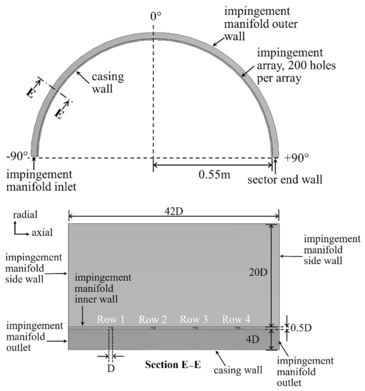
The single-entry ACC system geometry is a 180° sector of an impingement manifold, shown in
Figure 4. The inlet of the impingement manifold is at −90° in the circumferential direction, and the sector end wall is at +90°. The midpoint between inlet and endwall is at 0°. This convention was used to aid in describing any symmetry/asymmetry in the flow behaviour. Section E-E shows the rectangular cross-section of the manifold, with the side walls, and the four rows of holes exhausting to the surrounding pressure of 1 atm, and impinging on to the casing wall. Each row of holes comprises 200 holes across the 180° sector, totaling 800 holes in the CFD domain.
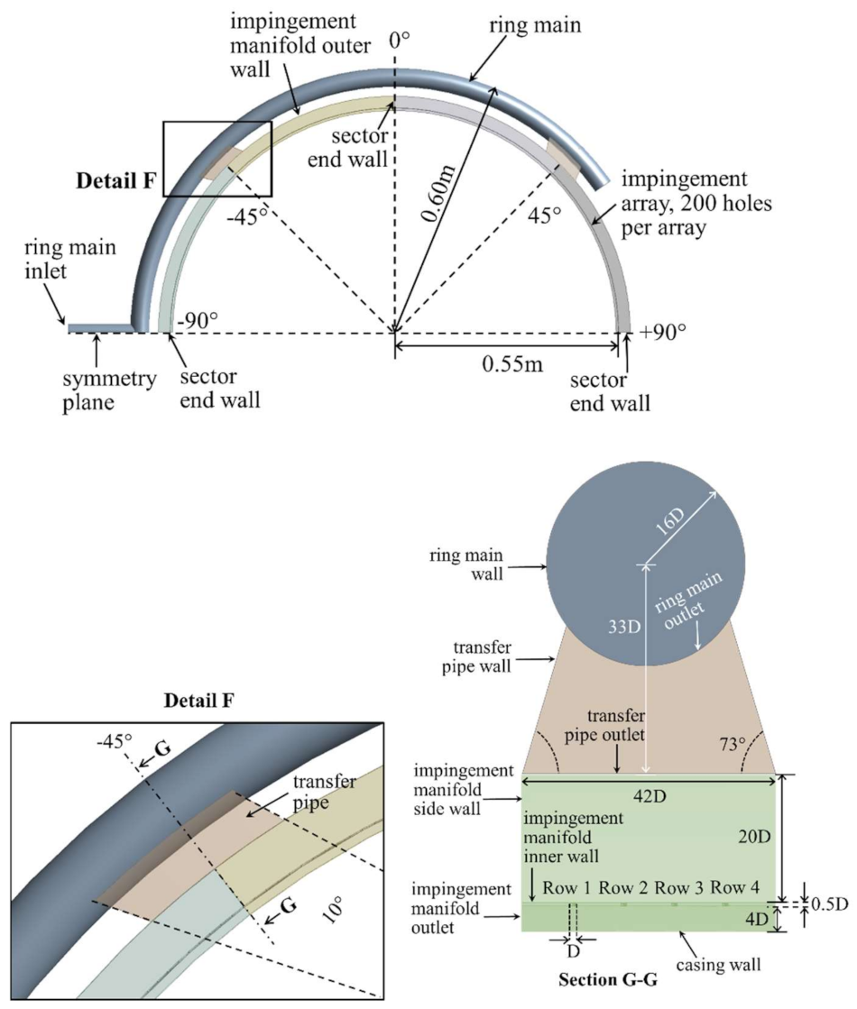
4.2. Multiple-Entry ACC System Geometry
The ring main system feeds the impingement manifold system through transfer boxes at every 90°, as shown in
Figure 5. Each transfer box feeds two 45° sectors of the impingement manifold. Each 45° sector of the impingement manifold has end walls, so there is no flow in between sectors. Detail F in
Figure 5 shows the ring main, transfer pipe and manifold assembly, and Section G-G shows the cross-section of the assembly. The flow through the ring main exits through the ring main outlet and enters the transfer pipe. It then exits the transfer pipe and enters the impingement manifold. The impingement manifold cross-section is identical to that of the single-entry ACC system.
5. CFD Setup
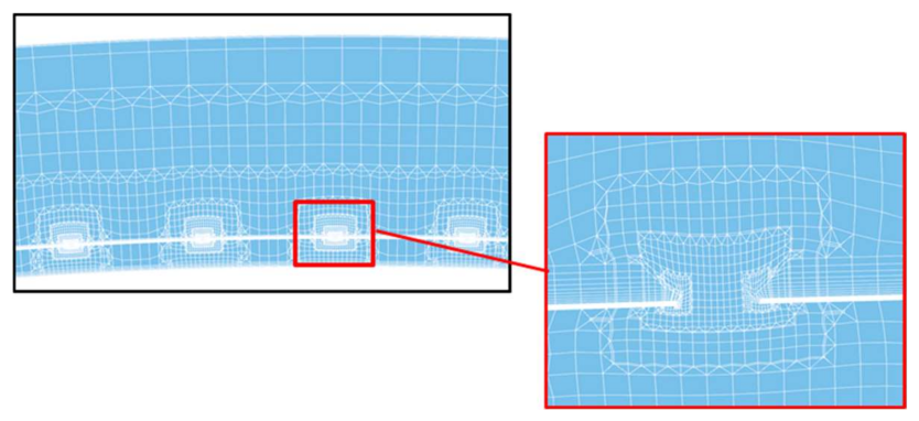
The computational grid for the impingement manifold was generated in BOXERmesh (Cambridge Flow Solutions, Cambridge, UK) [
15] with 31 million nodes, with a higher density of cells centred through the impingement holes, as shown in
Figure 6. The boundary layer along the impingement manifold inner wall was resolved with 15 layers of prism cells. Due to the computational expense of modelling a 180° sector with 800 holes, the main passage region of the manifold was kept relatively coarse. Similarly, the casing surface was resolved with 12 layers of prism cells to capture the boundary layer, with the area in between each hole kept relatively coarse. Each of the 800 holes was resolved with 20 cells across the diameter width D, but no prism layers. The y+ was approximately 1 on the impingement manifold inner walls. We used a wall resolved approach for the impingement manifold wall, and a wall function approach for the casing wall.
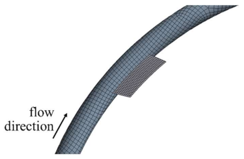
The ring main system with the transfer boxes was meshed in ANSYS Mesher (v17.1, ANSYS Inc., Canonsburg, PA, USA), with 113,440 nodes of hexahedral elements, as shown in
Figure 7. The ring main system was then combined with the same impingement manifold mesh as the single-entry case in the ANSYS CFX solver (ANSYS Inc., Canonsburg, PA, USA). Radiation was neglected in this study. Although radiation will have a non-negligible effect on the overall heat transfer distribution on the casing, this paper focuses on comparing the two systems in terms of the impingement manifold internal flow and the effect on hole flow. Radiation will be included for future studies on this topic. The case was modelled using the steady-state RANS approximation within the ANSYS CFX solver. The advantage of using this method was the desired steady-state, back-to-back comparison of the impingement HTC from both systems. A disadvantage is that a steady RANS method will not capture the inherent unsteadiness within the system, but at this stage, this was considered to be less important than the overall, steady impingement HTC performance of both systems. The k-ω SST turbulence model was used due to its versatility, robustness and relative success in predicting secondary flows where the turbulence can be assumed to be isotropic [
16]. The choice of mesh density is further discussed in the
Appendix A.
In order to compare the two designs, we consider three operating conditions, based on the maximum mass flow rate delivered to the impingement system at aircraft take-off, referred to as max. takeoff. The three conditions for each of the designs are 100% of max. takeoff, followed by 50% and 20%. The only boundary condition to change between 100%, 50% and 20% is the inlet mass flow rate. The details of the boundary conditions for each surface in both designs are provided in
Table 1. These boundary conditions originate from our industrial sponsor.
6. Data Reduction
We quantify the heat transfer coefficient (HTC) distribution and the total pressure loss coefficient () for each design. We consider HTC and the most appropriate metrics for aero-thermal performance assessment since flow rate, inlet temperature and wall/gas properties are the same in each comparison of single-entry vs. multiple-entry systems (for a given mass flow rate). Symmetricity and speed of response of the tip clearance control system are indicated by the HTC distribution and engine efficiency impact of the tip clearance system is indicated by .
The HTC has been defined as per Equation (1), where the heat flux,
is predicted from the numerical model. The temperature
is the casing temperature of 600 K, while
is a static temperature of 330 K (
Table 1).
HTC defined in this way accounts for heat pick up in the ring main, which is one of the main purposes of our study (i.e., the reduced cooling potential of the air in the multiple-entry system). Therefore, HTC is a global performance metric of the system. This is why the differences in HTC between the single-entry and multiple-entry system reported in this paper are larger than one would expect to see due to jet Reynolds number differences alone. If one defines the HTC with respect to the temperature at the inlet to the hole rather than the domain inlet, the HTC scales as expected with jet Reynolds number [19].
The total pressure loss coefficient used in this paper is defined as
where
is the total pressure at the inlet to the system,
is the total pressure at the inlet to the impingement hole, and thus varies around the circumference, and
is the total pressure drop across the entire single-entry system. This assumes that the static pressure at the outlet is equal to the total pressure at the outlet.
is subsequently a measure of the total pressure drop through the system up to the impingement holes, as a fraction of the entire total pressure drop of the system. This gives an indication as to the ‘useful total pressure drop’ through the system, as it is preferable to drop most pressure across the impingement holes. By normalizing both the single-entry and multiple-entry pressure drops by the single-entry total pressure drop, the two systems may be compared back-to-back.
The T-junction entry into the multiple-entry domain is not exactly matched between the single-entry and multiple-entry systems. The T-junction is obviously too far from optimum to allow for a fair comparison between the two systems. In order to remove this T-junction from the pressure drop comparison, the inlet total pressure for the multiple-entry system is defined just upstream of the first transfer box. This allows values between the multiple-entry and single-entry systems to be compared, thus eliminating this inlet discrepancy.
7. Results and Discussion
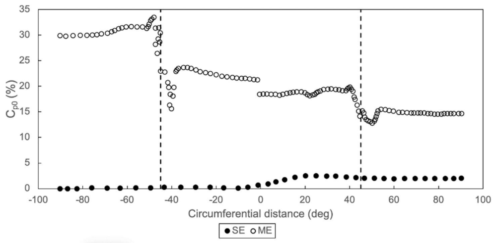
Figure 8 shows the total pressure loss coefficient through the single-entry and multiple-entry systems. Between 15% and 30% of the available total pressure drop in the multiple-entry system is used to overcome the loss-generating mechanisms in the ring main and transfer boxes. Total pressure loss is reduced with a circumferential position for the multiple-entry system because the flow entering the second quadrant (0° to 90°) need only go through an S-bend in the second transfer box, while flow entering the first quadrant (0° to −90°) must flow through a U-bend.
In comparison, the feed pipework for the single-entry system only uses 2% of the total available pressure drop, with the rest used across the impingement holes. As a consequence, the driving pressure ratio across each impingement hole in the multiple-entry system is less than in the single-entry system, for the same overall boundary conditions and impingement geometry.
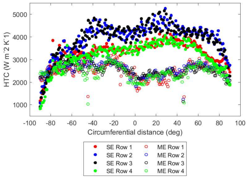
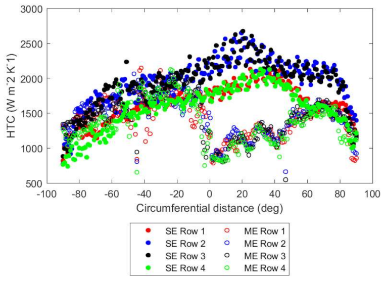
Consequently, the average heat transfer coefficient on the outer side of the turbine casing is 77% greater in the single-entry system than the multiple-entry system (
Figure 9), primarily due to increased heat pick up in the ring main in the multiple-entry system through the ring main (
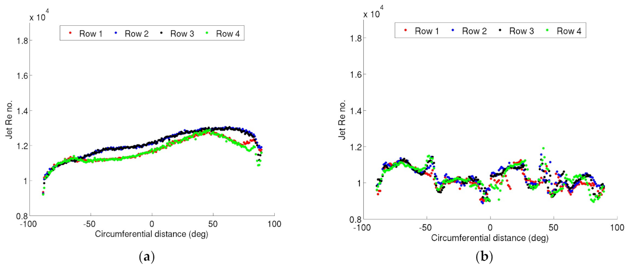
Figure 10), and secondarily due to a jet Reynolds number 1.2 times greater in the single-entry system than the multiple-entry system (
Figure 11). The Mach number throughout the domain is less than 0.3, except for the inlet to the multiple-entry system before the ring main, where it exceeds 0.5.
The jet Reynolds number shown in
Figure 11 is lower in the multiple-entry case than the single-entry case because the average discharge coefficient of the impingement holes in the single-entry system is 8% lower than that of the multiple-entry case; a lower discharge coefficient for the same overall mass flow rate requires greater localised jet velocity, leading to greater HTC enhancement in the single-entry system. The cross-flow in the single-entry system helps to enhance impingement heat transfer over the multiple-entry system. The temperature of the air feeding the impingement holes is greater in the multiple-entry system compared to the single-entry system, due to the heat picked up in the ring main.
As can be seen from
Figure 8,
Figure 9,
Figure 10 and
Figure 11, the circumferential HTC, Reynolds number, static temperature and total pressure loss coefficient vary more smoothly in the single-entry system than the multiple-entry system. In the multiple-entry system, the aero-thermal field in the vicinity of the transfer boxes is highly non-uniform due to the abrupt S- or U-bend from ring main into the casing manifold, resulting in large, local circumferential variations in impingement hole mass flow rate compared to the single-entry system. The locations of the transfer boxes are visible in at −45° and +45°.
In contrast, the aero-thermal field gradients between each row are lower in the multiple-entry system than in the single-entry system. The sectorised annulus and U- or S-bends in the multiple-entry system prevent the formation of fully developed counter-rotating secondary flow vortices by reducing the available smooth development length, limiting axial HTC variation. The secondary flow vortices are clearly seen in the single-fed system after an initial entry length, as shown in
Figure 12, indicated by the two kidney-shaped contours around Rows 1 and 4. This gives flow preference to the two inner impingement rows which generate 26% more HTC than the two outer impingement rows, with the differences more pronounced at the four peaks at −65°, −35°, +25° and +75°. These peaks represent the onset of the secondary flow vortices as the flow moves around each 45° bend in the 180° sector. The vortices are set up by the centrifugal and pressure forces acting on the faster moving core flow and causing an adverse pressure gradient [
17]. The effect is less prominent in the two outer rows.
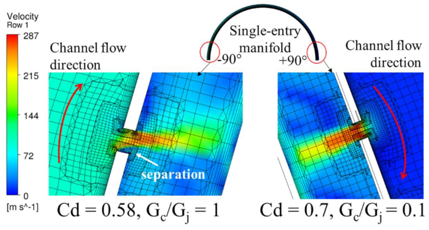
The low values of HTC for the single-entry case in the circumferential region between −90° and −70° (
Figure 9) are caused by the flow separation within the hole due to the adverse turning angle and higher manifold channel mass velocity (G
c). This means that the flow is not perpendicular to the impingement manifold inner wall as it exits through the hole, as seen in
Figure 13, and has a lower hole discharge coefficient. The flow close to +90° has a higher hole discharge coefficient because of the lower channel mass velocity to jet mass velocity ratio (G
j), i.e., lower G
c/G
j. This highlights a scope for design optimisation of the single-entry system in this region.
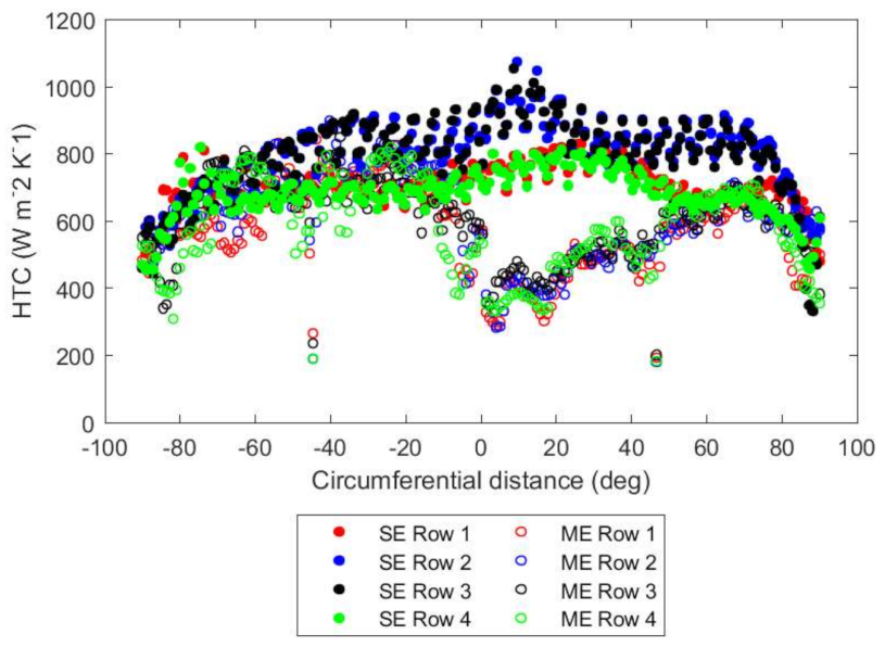
The 50% and 20% mass flow rate conditions show similar trends for the HTCs in
Figure 14 and
Figure 15, with lower absolute levels due to the reduced mass flow rates. For the single-entry case, there are now three peaks instead of four, suggesting that the Reynolds number of the manifold channel affects the formation of the secondary flow features. The HTC delivered by the multiple-entry system is similar in value to the single-entry system between −90° and −20°, while the sector from 0° to 45° sees a large drop in HTC values. This is likely due to this sector being upstream of the 45°–90° sector, but is fed by the same transfer box. Hence, the flow exiting the 45° transfer box not only has decreased total pressure due to frictional losses in the ring main, but now has to work against the forward momentum to deliver mass flow to the upstream sector.
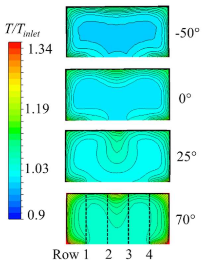
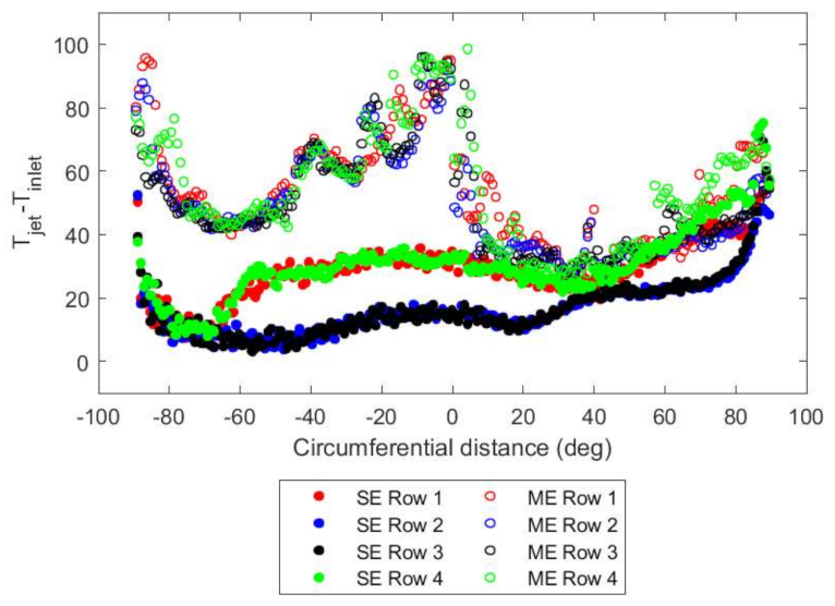
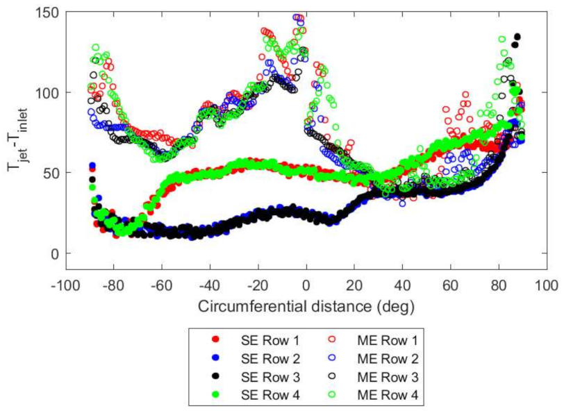
In both systems, the temperature pick up increases and asymmetry increases as the mass flow rate is reduced, as shown in
Figure 16 and
Figure 17. The overall static temperatures in the multiple-entry system are higher since both the ring main and the transfer pipes are exposed to the zone temperature of 600 K. The temperatures in the multiple-entry system reach a peak at −90°, 0° and +90° when the flow encounters the sector walls and the dynamic pressure is reduced to a minimum. Compared to the single-entry system, the temperature peaks are at −90° and +90°, again due to the sector walls. The increase in temperature at −60° for Rows 1 and 4 indicates the onset of the secondary flow vortices as the flow travels around the bend. This trend becomes more apparent as the mass flow rate is reduced (
Figure 16 and
Figure 17), as the strength of the vortex separation increases. The onset of secondary flow formation also moves closer towards the inlet. A comparison of total temperatures would yield similar results with the absolute values shifted slightly higher by approximately 10 K. The comparison trends still hold.
8. Conclusions
In this paper, we have compared using CFD the aero-thermal performance of two candidate casing manifolds for supplying an impingement-actuated active tip clearance control system for an aero-engine HP turbine. The two geometries are (a) single-entry: an annular manifold fed at one circumferential location; (b) multiple-entry: a casing manifold split into four annular sectors, with each sector supplied separately from an annular ring main.
From the results of this computational study, and in consideration of holistic aero-engine design factors, we conclude that a single-entry system is closer to an optimal solution than a multiple-entry system. The reasons are summarised as follows.
8.1. Engine Efficiency
All else being equal, a single-entry system requires less overall driving pressure ratio than a multiple-entry system to provide the same heat transfer performance, since the total pressure loss coefficient is less and the average HTC is greater in the single-entry system. In order for the multiple-entry system to generate the same HTC as the single-entry system, it must operate at a higher overall system pressure ratio in order to achieve the same mass flow rate and jet Reynolds number. Subsequently, the manifold system must be supplied from a higher pressure stage of the compressor, reducing engine efficiency.
8.2. Response Time
The single-entry system transfers heat faster than the multiple-entry system for the same overall pressure ratio, since the HTC (convective heat transfer) and mass flow rate (advective heat transfer) are greater in the single-entry system. Therefore, the active tip clearance system responds faster in the single-entry system, with a corresponding increase in engine efficiency. Seen from another perspective, the multiple-entry system would require a greater overall pressure ratio than the single-entry system to achieve the same speed of response (HTC), which is less efficient for the reasons described previously.
8.3. Ease of Optimisation
The systems presented in this paper are early iterations of production casing manifold systems. An important consideration when down-selecting the manifold supply system is the ease with which the designs may subsequently be optimised, to maximise HTC field uniformity on the casing and to minimise the flow requirement. In this respect, aero-thermal fields that are smooth with small gradients and deterministic flow features are a distinct advantage.
The aero-thermal fields in the single-entry system have much smoother, smaller gradients than those in the multiple-entry system. While the counter-rotating vortices in this iteration of a single-entry system generate non-uniform HTC in the axial direction, they do so in a way that is consistent and well understood. The axial HTC non-uniformity may easily be remedied, for example, by increasing the hole sizes of the outermost impingement rows. Similarly, the circumferential HTC distribution in the single-entry system is predictable, based on reliable discharge coefficients, blowing ratios and pressure drop. Circumferential HTC may, for example, be optimised by varying the cross-sectional area of the manifold with circumference or varying the spacing/diameter of the holes. In theory, optimisation of the single-entry system could be achieved through hand calculation.
There are large, local aero-thermal field variations in the multiple-entry system, and these are highly sensitive to the flow and geometric boundary conditions. Any optimisation must then occur at a very fine level to capture the local variation, and it is likely that hole spacing and diameters will vary discretely, rather than varying smoothly and continuously as in the single-entry system. This necessitates a more computationally expensive optimisation method, e.g., CFD coupled with geometry optimisation schemes. Even after optimisation, a multiple-entry system will be highly sensitive to uncertainties in boundary conditions, numerical errors and fluid approximations because of the steep aero-thermal field gradients.
8.4. Weight, Cost and Complexity
Clearly, the weight of the single-entry system is less than the weight of the multiple-entry system, because the multiple-entry system incorporates a ring main and transfer boxes. Not only does this affect the power-to-weight ratio of the engine, it also increases the complexity and cost of design, manufacture, operation and maintenance.
The next stage in the engine development process is design optimisation. While the manifold designs presented in this paper are by no means local maxima in performance, this study provides strong evidence that the global optimum for tip clearance casing manifold design is far nearer a single-entry system than a multiple-entry system. However, the issues encountered by the multiple-entry system may help inform future design scenarios where a controlled circumferential non-uniformity in HTC is sought to correct asymmetric clearance. This would require multiple valves and/or an iteration of the ring main–transfer box assembly design considered in this study.


