2.1. Characterization of the Aerogels
In a previous study we reported the two-step synthesis of N-doped carbon aerogels based on the prepolymerization of melamine-resorcinol-formaldehyde (MRF) mixtures [
26,
27]. Regardless of the solution pH and M/R molar ratio, the hydrogels prepared by the conventional one-step route displayed essentially a microporous character, as opposed to the meso-/macroporous network of those prepared upon the prepolymerization of the precursors. These MRF aerogels presented promising electrochemical features due to a unique pore structure dominated by large pores, and an improved wettability provided by the presence of N-surface groups. The materials still displayed poor electrical conductivity (although superior to that of RF aerogels) and limited mechanical characteristics (large deformation and bending upon carbonization), for which the use of large monolithic electrodes was quite challenging.
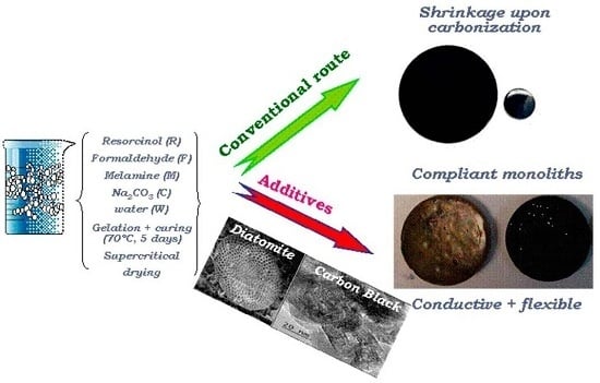
We herein report a simple modification of the above-mentioned method for the synthesis of MRF aerogels consisting of carrying out the sol-gel polymerization of the precursors in the presence of two additives: diatomaceous earth as low cost sacrificial structural additive to improve the stiffness of the aerogels, and a carbon black—commonly used in electrochemical applications—to increase the conductivity of the materials. The diatomite (D) used (Nanolit, K6) is a fine-grained siliceous sediment of biogenic origin (skeletal remains of microscopic single-celled diatoms; average particle size 12 μm; chemical composition: 89.2 wt% SiO2, 4 wt% Al2O3, 1.7 wt% Fe2O3, 0.5 wt% CaO, 0.3 wt% MgO); the carbon black (B) additive (Superior Graphite Co.; average particle size 6 μm; ash content below 0.05 wt%, volatiles below 0.15wt.%) is characterized by a high electrical conductivity (ca. 10 mS/cm). The presence of diatomite and carbon black in the aerogels is indicated by either “D” or “B”, respectively. The diatomite was etched off (using HF), unless otherwise stated.
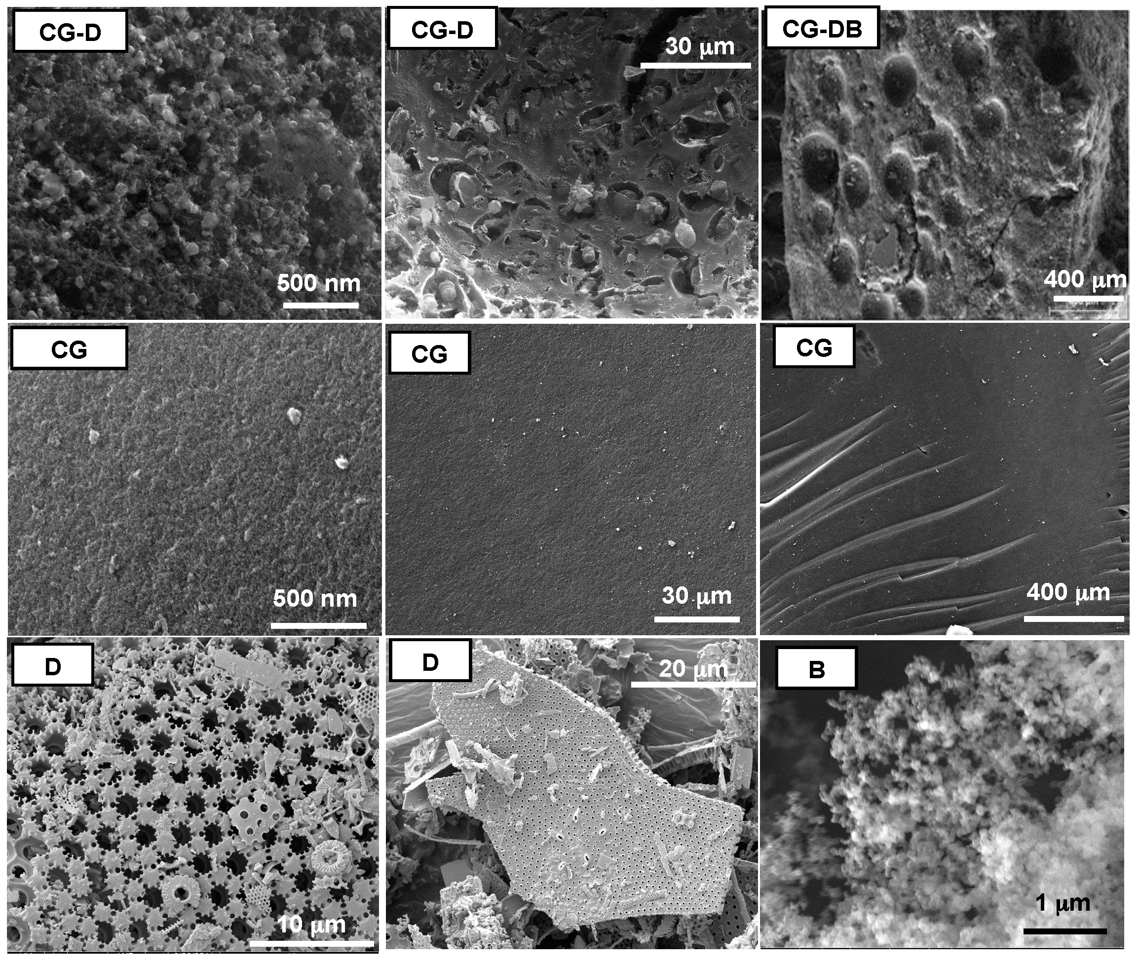
Figure 1 shows SEM images of the carbon aerogels displaying the differences on a macroscopic scale depending on the presence of additives during the synthesis. All the aerogels prepared in the presence of diatomite (samples CG-D and CG-DB) presented similar SEM images, and are characterized by a relatively rough surface with large holes, likely inherited from the siliceous additive.
Figure 1.
Scanning Electron Microscopy (SEM) images representative of the studied monolithic aerogels prepared in the presence and absence of the additives. Images of the diatomite (sample D) and the carbon black (sample B) are also shown for clarity.
Figure 1.
Scanning Electron Microscopy (SEM) images representative of the studied monolithic aerogels prepared in the presence and absence of the additives. Images of the diatomite (sample D) and the carbon black (sample B) are also shown for clarity.
Conversely, the MRF aerogels displayed a smooth compact surface formed by densely packed spherical particles. This observation is in agreement with the bulk density values of the monoliths compiled in
Table 1. While CG and HG materials featured the low density values expected for aerogels, CG-D and CG-DB displayed values close to 0.15 g·cm
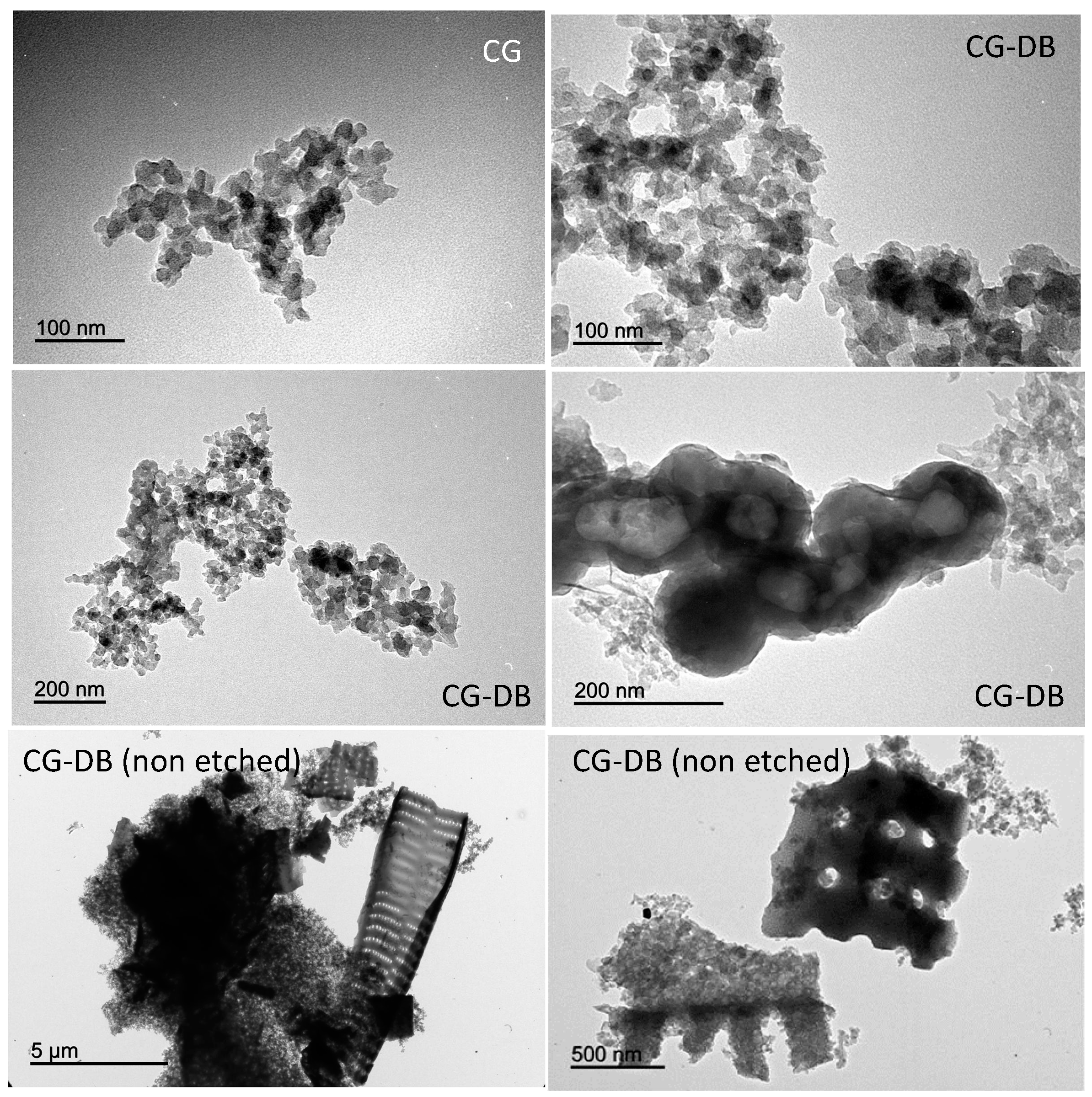
−3, likely due to the large voids created after removal of the diatomite. The presence of the nanometric particles of carbon black can be seen in the TEM images in
Figure 2 at different magnifications, where the characteristic spherical aggregates of the carbon black particles (seen also as black spots in the low magnification images) appear distributed within the disordered carbon matrix of the aerogels. The aggregates have varied sizes, and are also seen in the samples before the HF etching treatment.
Table 1.
Main textural characteristics of the monolithic aerogels obtained from N2 adsorption isotherms at −196 °C. Aerogels before (HG) and after (CG) carbonization are compared.
Table 1.
Main textural characteristics of the monolithic aerogels obtained from N2 adsorption isotherms at −196 °C. Aerogels before (HG) and after (CG) carbonization are compared.
| Sample | Bulk Density (g·cm−3) | SBET A (m2·g−1) | VTOTAL B (cm3·g−1) | VMICROPORES C (cm3·g−1) | VMESOPORES D (cm3·g−1) |
|---|
| HG | 0.41 | 212 | 1.44 | 0.07 | 1.30 |
| HG-D | 0.64 | 101 | 0.58 | 0.04 | 0.51 |
| HG-DB | 0.63 | 237 | 0.51 | 0.05 | 0.45 |
| CG | 0.52 | 522 | 1.55 | 0.19 | 1.30 |
| CG-D (non etched) | 0.50 | 230 | 0.85 | 0.09 | 0.74 |
| CG-D | 0.15 | 409 | 1.23 | 0.16 | 0.99 |
| CG-DB (non etched) | 0.53 | 118 | 0.41 | 0.05 | 0.35 |
| CG-DB | 0.16 | 470 | 0.75 | 0.17 | 0.54 |
| Diatomite | -- | 28 | 0.08 | 0.01 | 0.07 |
| Carbon Black | -- | 23 | 0.17 | 0.01 | 0.16 |
Figure 2.
Transmission Electron Microscopy (TEM) images representative of the carbon aerogels showing the presence of the additives.
Figure 2.
Transmission Electron Microscopy (TEM) images representative of the carbon aerogels showing the presence of the additives.
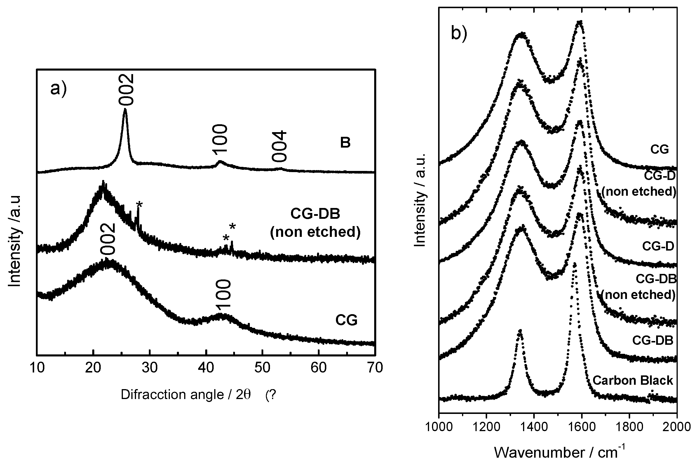
A more detailed analysis of the structure of the carbon aerogels can be inferred from XRD and Raman spectroscopy. The XRD patterns show broad bands at
ca. 23° and 43° (2θ), characteristic of the (002) and (100) reflections of disordered carbons (
Figure 3a) for sample CG. Oppositely, the pattern of the carbon black shows a prompt and narrow peak at
ca. 25.7° corresponding to the (002) reflection, along with less intense peaks at
ca. 42.6° and 53.3° evidencing a more ordered structure than the aerogels. Due to the small amount of conductive additive used, peaks due to the presence of the carbon black were not observed in the XRD patterns of sample CG-DB. Similar observations were reported for the series of aerogels loaded with carbon black and subjected to activation under CO
2 atmosphere to develop the porosity [
21,
28].
Figure 3.
(a) X-ray diffraction patterns and (b) Raman spectra of the carbon aerogels showing the presence of the additives.
Figure 3.
(a) X-ray diffraction patterns and (b) Raman spectra of the carbon aerogels showing the presence of the additives.
On the other hand, the peaks due to the diatomite (
ca. 27.7°, 43.4°, and 44.6°) are clearly observed in sample CB-DB non etched (marked with asterisks in
Figure 3a). The first-order Raman spectra of the aerogels also showed the typical profiles ascribable to disordered carbons carbonized (
Figure 3b). The two broad bands at 1344 cm
−1 (D band) and 1590 cm
−1 (G band) are assigned, respectively, to the “disorder-induced” mode upon the lack of long-range translation symmetry and to the “in plane” displacement of carbon atoms in the graphene sheets [
29]. The prominent I
D band of the carbon aerogels contrasts with the less significant one recorded for the carbon black with a more ordered structure.
The I
D/I
G ratios calculated upon deconvolution of the Raman bands give information about the level of graphitization of the aerogels (
Table 2). The samples loaded with carbon black displayed slightly lower I
D/I
G ratio than CG or CG-D (either etched or non-etched), confirming the higher structural order provided by the carbon black. Indeed, the low I
D/I
G ratio obtained for the carbon black corroborated its ordered structure, also in agreement with the XRD patterns.
Table 2.
Raman parameters (shift and Full Width at Half Maximum, FWHM) for the D and G bands calculated from the deconvoluted spectra.
Table 2.
Raman parameters (shift and Full Width at Half Maximum, FWHM) for the D and G bands calculated from the deconvoluted spectra.
| Sample | ID/IG | D Shift (cm−1) | G Shift (cm−1) | D FWHM (cm−1) | G FWHM (cm−1) |
|---|
| CG | 2.08 | 1347.14 | 1595.57 | 177.13 | 72.73 |
| CG-D (non-etched) | 1.85 | 1346.80 | 1597.32 | 178.01 | 73.75 |
| CG-D | 1.95 | 1346.37 | 1595.64 | 179.68 | 70.96 |
| CG-DB (non-etched) | 1.76 | 1346.34 | 1598.00 | 181.67 | 75.06 |
| CG-DB | 1.82 | 1347.56 | 1596.95 | 169.13 | 71.37 |
| B | 0.62 | 1340.23 | 1569.63 | 42.73 | 35.24 |
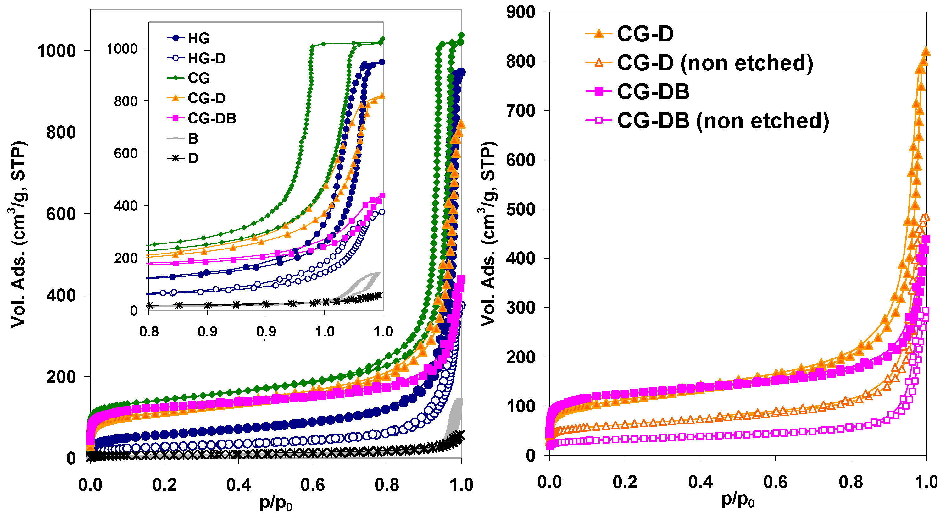
The effect of the additives in the porosity of the resulting aerogels can be seen in
Figure 4 showing the N
2 adsorption isotherms of the prepared materials; the main textural parameters are also compiled in
Table 1. First of all, it is important to highlight that all the materials displayed high porous features, confirming that the incorporation of the additives (either B or D) does not hinder the polycondensation of the reactants [
12,
18,
26,
28]. This is outstanding considering the large amount of diatomite used (
ca. 50 wt%) and the fact that according to the literature, the polycondensation of MRF mixtures is very sensitive to operational parameters such as small pH changes [
26]. Comparatively, the amount of carbon black added was smaller (
ca. 0.9 wt%), and our previous investigations showed that small amounts of this additive do not impede the polymerization of either MRF or RF mixtures [
21,
26].
Figure 4.
N2 adsorption isotherms at −196 °C of the studied aerogels (inset: magnification of the high relative pressure range to show the difference in the hysteresis loops). Data corresponding to the additives (diatomite and carbon black) is also included for clarity.
Figure 4.
N2 adsorption isotherms at −196 °C of the studied aerogels (inset: magnification of the high relative pressure range to show the difference in the hysteresis loops). Data corresponding to the additives (diatomite and carbon black) is also included for clarity.
Furthermore, all the samples displayed a well-developed porosity with type IVb isotherms according to the new IUPAC classification [
30] with prominent hysteresis loops in the desorption branch, characteristic of mesoporous adsorbents. The large adsorbed volume at relative pressures below 0.3 also indicates the presence of a micropore network, characteristic of so-called colloidal aerogels. The presence of D and B during the polymerization of the reactants provoked important changes in the porous features of the resulting aerogels; particularly in the position of the hysteresis loops (hence, mesopore size) and the total pore volumes (
Figure 4). It should also be noted that the aerogels retain the porous structure after etching off the siliceous additive (the porous structure does not collapse), confirming that the porosity is due to the adequate cross-linking of the MRF reactants. The large pore volumes and hysteresis loops suggest that the polycondensation of the monomers is slowed down in the presence of the additives (either B or D), as already observed in the case of carbon black alone [
21,
26,
28]. This would lead to a lower degree of cross-linking of the monomers, generating weakly branched clusters that tend to form larger colloidal aggregates in progressively larger pores (pore coarsening) [
1,
4].
On the other hand, a significant fall in the pore volumes was observed for the samples synthesized in the presence of the diatomite, even after the HF etching (
Table 1). This affected the whole range of relative pressures, hence D-containing aerogels displayed lower surface area values than the pristine materials. Otherwise, the addition of carbon black along with the diatomite (sample CG-DB) yielded a decrease in the mesopore volume (compared to CG-D); this contrasts with the trend observed for other composite aerogels prepared when only carbon black was used as additive, which led to an increase in the pore volume in the mesopore range [
21,
26,
28]. When the polycondensation of the reactants is carried out in the presence of both D and B, the formation of large pores is still dominant, which is indicative of the formation of weakly branched clusters during the polymerization reaction; the low pore volumes (compared to D- or B-containing aerogels) suggest that the extent of the assembling of the clusters in large aggregates is partially hindered by the large amount of diatomite.
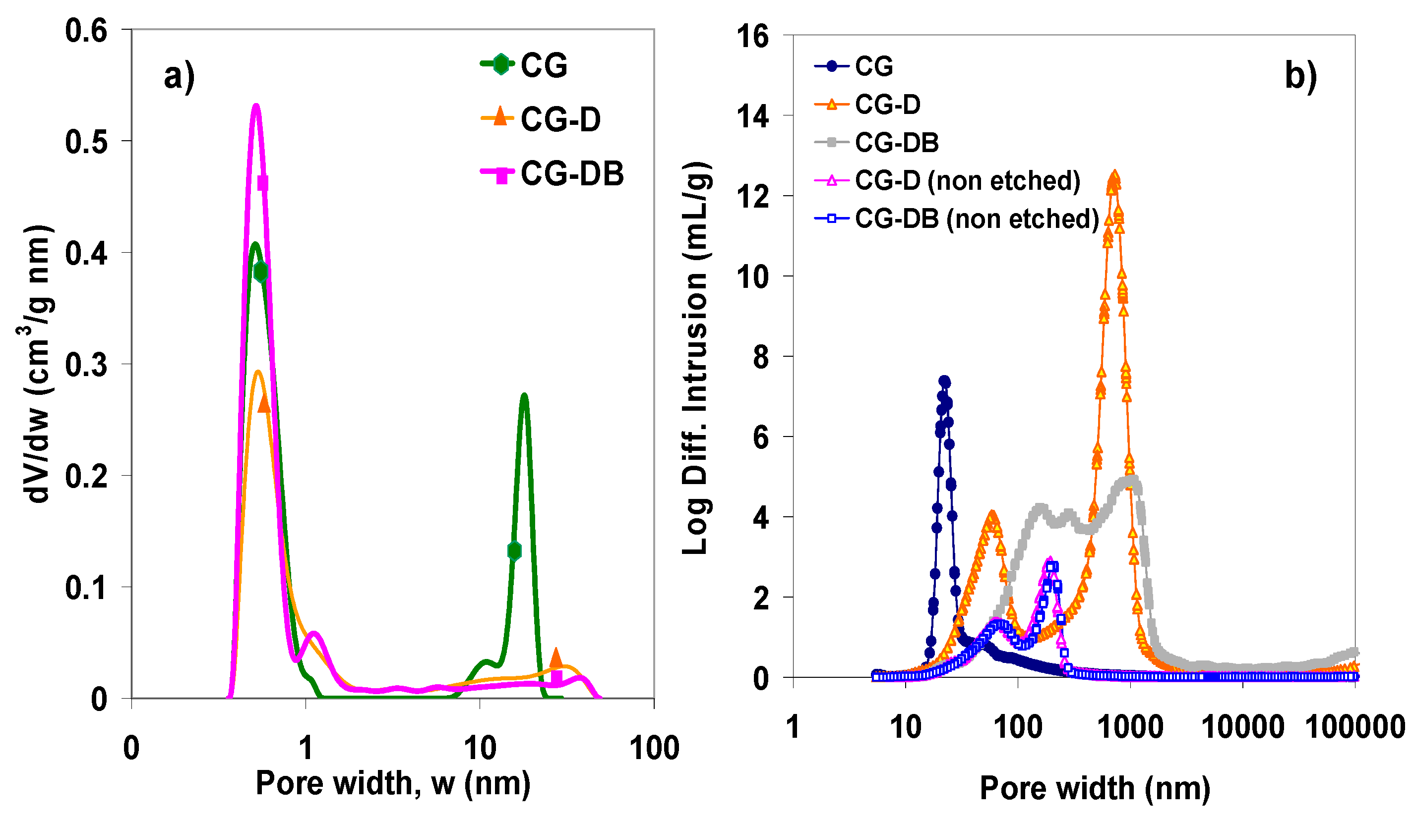
Further information on the nanotexture of the synthesized aerogels was obtained from the analysis of the pore size distribution.
Figure 5a shows the distributions obtained by analysis of the N
2 adsorption data corresponding to the carbon aerogels after carbonization and removal of the diatomite, as these are the samples of interest for electrochemical applications. In agreement with the shape of the isotherms (
i.e., position of the hysteresis loops), the effect of the additives is noticed most remarkably in the distribution of larger pores.
Figure 5.
(a) Distribution of pore sizes of the carbon aerogels prepared in the presence of diatomite, after removal of the siliceous sacrificial additive obtained by the 2D-NLDFT method applied to the gas adsorption data; (b) Distribution of pore sizes in the macropore range obtained from mercury porosimetry.
The pristine aerogel (sample CG) displayed the typical monodispersed distribution of pore sizes in the mesopore range, with the average mesopore size around 18 nm [
21,
22]. In contrast, the composite aerogels treated with diatomite and carbon black displayed a broad distribution in the mesopore range, between 5 nm and 40 nm. Additionally, the incorporation of the diatomite in the synthesis gave rise to the formation of large macropores, as evidenced by mercury porosimetry (
Figure 5b), which were not present in the pristine CG carbon aerogel. This clearly shows the capability of the siliceous additive to modify the porous network of the carbon matrix creating large voids in the meso-/macropore range.
2.2. Mechanical Properties of the Aerogels
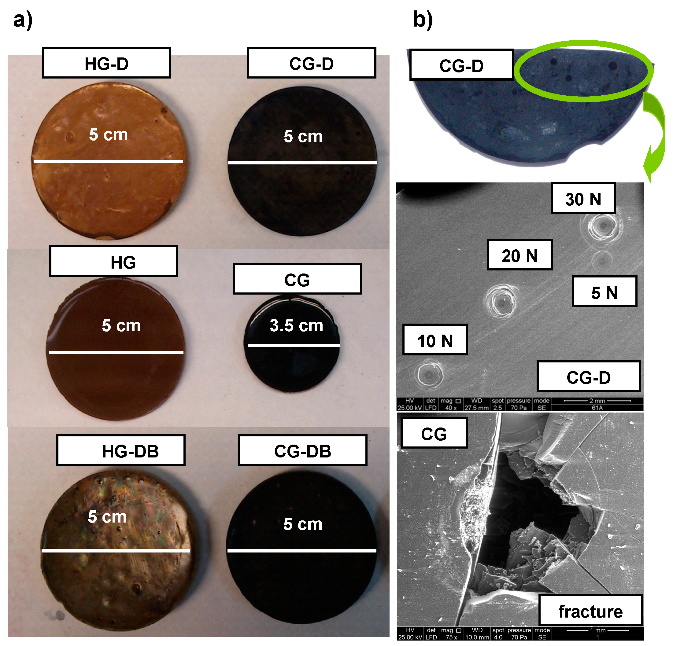
In addition to being highly porous, the aerogels prepared in the presence of the additives were mechanically more compliant. The aerogels ranged from brittle to sponge-like solids when D was incorporated—even after etching off the diatomite—regardless of the presence of the carbon black (
Figure 6). The typical shrinkage of the monoliths after carbonization—due to the evolution of volatiles upon densification of the carbon matrix—is shown in
Figure 6. Values up to a 30% reduction in volume are typically reached in RF and MRF aerogels (
Table 3); this behavior is independent of the composition of the aerogels [
27], although it is more pronounced for MRF formulations. For the samples CG-D and CG-DB prepared in the presence of diatomite, the carbonized disks preserved their dimensions, even after the removal of the siliceous skeleton, likely due to the open pore structure of the aerogels provided by the diatomite (
Figure 5b), which would facilitate the evolution of the volatiles upon carbonization.
Figure 6.
(a) Images of the studied monolithic aerogels showing the characteristic shrinkage upon carbonization and (b) examples of the characteristic fingerprints of the aerogels after different loadings.
Figure 6.
(a) Images of the studied monolithic aerogels showing the characteristic shrinkage upon carbonization and (b) examples of the characteristic fingerprints of the aerogels after different loadings.
Table 3.
Shrinkage after carbonization (in C-series) of the aerogels and response to the Crushing Strength Tests. The initial dimensions of all the specimens were ca. 5 cm.
Table 3.
Shrinkage after carbonization (in C-series) of the aerogels and response to the Crushing Strength Tests. The initial dimensions of all the specimens were ca. 5 cm.
| Sample | Shrinkage (%) | Rigidity § (N/mm) | Maximum Load § (N) | Toughness § (N·mm) | Behavior on Crushing Strength Tests §§ |
|---|
| HG | -- | 324 | 17 | 1.2 | Brittle, fracture upon load of 21 N |
| CG | 30.8 | 456 | 28 | 0.8 | Brittle, fracture upon load of 14 N |
| CG-D | 5.4 | 65 | 23 | 3.2 | Flexible, no fracture after loading at 30 N |
| CG-DB | 5.2 | 27 | 10 | 2.9 | Flexible, no fracture after loading at 30 N |
These differences in the consistency of the aerogels depending on the use of additives were corroborated by the mechanical tests (performed on the samples of electrochemical interest after etching off the diatomite). First of all we applied a Crushing Strength Test as a screening tool to evaluate the resistance of the materials to fracture upon applying a force up to 30 N [
31]. The pristine aerogels (HG and CG) showed the behavior of a rigid material (similar to that of non-porous phenol-formaldehyde resins) with a conchoidal fracture after compression above 30 N (
Figure 6,
Table 2). Conversely, the aerogels synthesized in the presence of the D followed a different pattern, being gradually deformed with increasing load. The characteristic fingerprint left by the load is shown in the images in
Figure 6 for CG-D (a similar behavior was obtained for all the materials prepared in the presence of the D additive); the absence of fracture after 30 N evidences the somewhat flexible character of the aerogels that undergo deformation with the strength without fracture.
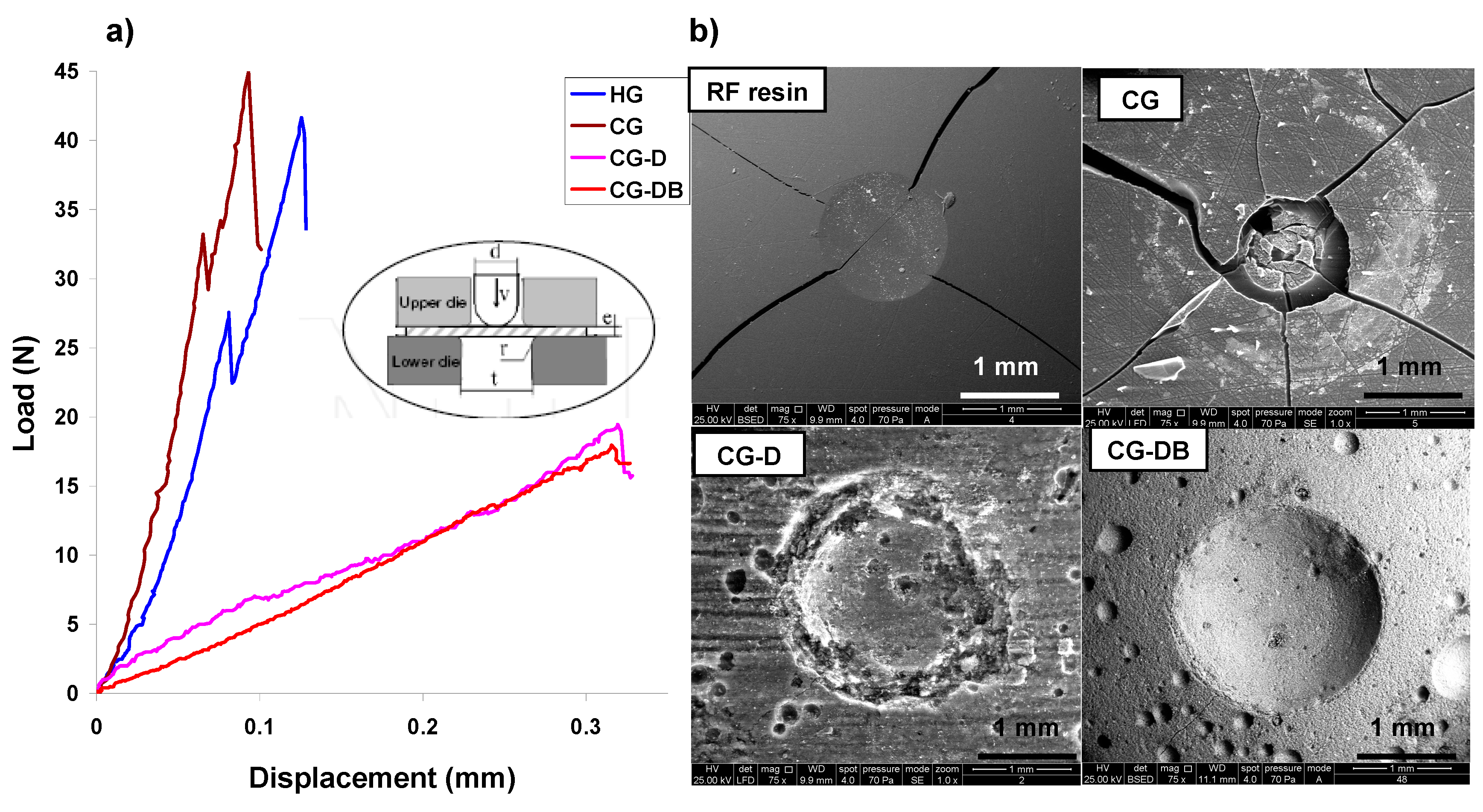
The mechanical properties were also investigated by means of Small Punch Tests [
27,
32].
Figure 7 shows the effect of both additives on the load-displacement curves (LDC) from biaxially stretched tests performed on the aerogels. The change from a stiff and brittle behavior of samples HG and CG to a compliant and flexible character of the materials when diatomite was used as additive in the synthesis, is seen in the differences in the shape of the LDC curves. For the aerogels without D, a linear load-displacement behavior with a steep slope is observed, followed by an abrupt drop of the load to zero after reaching the maximum load (associated with pop-in crackings) and leading to a brittle fracture (
Figure 7).
Figure 7.
(a) Load-displacement curves (LDC) of the aerogels determined by the Small Punch Tests under quasi-statical conditions (inset); (b) Characteristic fingerprint of the fracture after the Small Punch Tests on the aerogels (data of a brittle facture on a phenol-formaldehyde resin is also included for comparison purposes).
When D was used, the LDC profiles exhibit a much more compliant behavior with a smoother slope extending towards higher displacement values before the first crack is recorded, indicating a more flexible behavior than with the corresponding D-free aerogels; this is attributed to the presence of large voids inherited from the siliceous skeleton, as confirmed in the SEM images (
Figure 1). The maximum load and rigidity values calculated from the experimental LDC curves at the onset of the first crack and the slope of the LDC curve before the first crack, respectively, are listed in
Table 3. The stiffness and deformation capacity of the materials are determined by the maximum load values; as seen, aerogels CG and HG prepared in the absence of diatomite are more rigid (
Table 3) than those of CG-D and CG-DB. This is in agreement with the brittle behavior CG and HG observed in the crushing strength tests and the conchoidal fractures upon loading between 14 Nand 21 N (
Table 3), as opposed to the compliant character of samples CG-D and CG-DB. The maximum load up to the first pop-in crack is quite similar for all the samples, but CG-D and CG-DB exhibit much higher displacements before the first cracks are observed, indicating their toughness and flexible character.
2.3. Electrochemical Characterization of the Aerogels
The electrochemical characterization of the materials was performed by using cyclic voltammetry in 0.1 M NaCl using a 3-electrode cell configuration in a Swagelok-type cell.
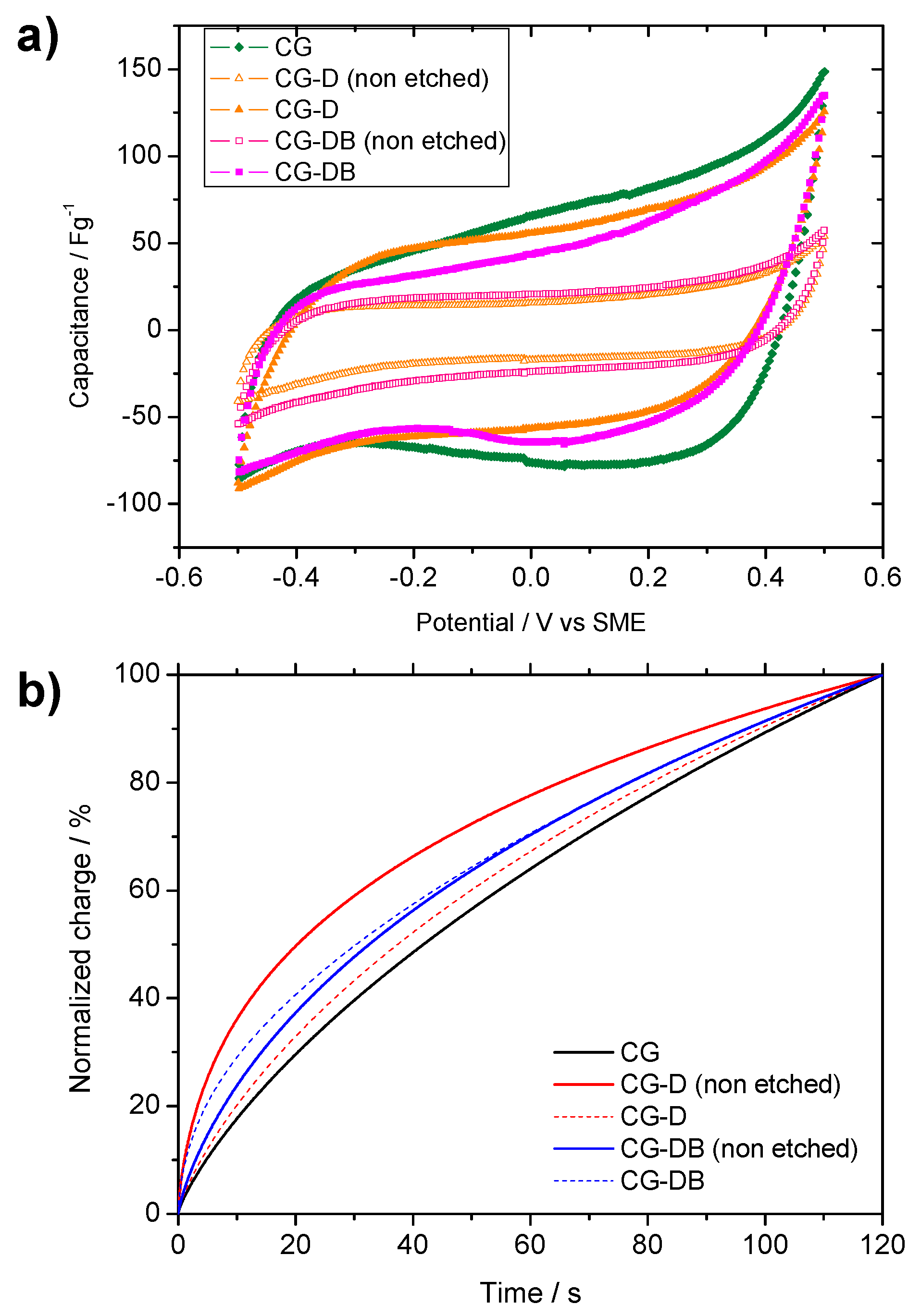
Figure 8a shows the corresponding voltammograms obtained for the electrodes before and after the removal of the silica additive. As seen, the curves show the box-shape profile characteristic of the capacitive behavior of porous electrodes upon polarization (
cf. formation of the double layer and adsorption of ions at the electrode surface due to electrostatic interactions). The capacitance value of the aerogel prepared in the absence of additives was 80 ± 3 F·g
−1; this is the highest value for the studied materials, which is in agreement with the large micropore volume of this sample (
Table 1). The effect of the diatomite incorporation in the CG-D sample was to drastically reduce the capacitance value to 20 ± 1 F·g
−1. This fact agrees well with the textural analysis that revealed a large drop in the specific surface and pore volumes (
Table 1). Similarly, a low capacitance was recorded for sample CG-DB (24 ± 1 F·g
−1) evidencing that diatomite etching is necessary to provide a suitable capacitive response for ion electrosorption. Thus, after etching off the siliceous skeleton (samples CG-D etched and CG-DB etched), the capacitance values increased up to 59 ± 4 F·g
−1 and 53 ± 3 F·g
−1. These values are still lower than that recorded for CG aerogel, although correlate well with their differences in porosity. It is evident that the improved macroporosity (at expense of the microporosity) does not lead to an increase of capacitance with respect to the pristine CG (since electrosorption of ions occurs mainly in the micropores). However, it is expected to have a more significant influence on the accessibility of ions from the electrolyte. To unveil this question, the kinetic response of the electrodes was determined by different procedures.
Figure 8.
(a) Cyclic voltammograms of the studied aerogels recorded at 0.5 mV/s in 0.1 M NaCl; (b) Normalized relaxation chronocoulometric curves recorded for the studied samples after a potentiostatic pulse of 300 mV for 120 s.
Figure 8.
(a) Cyclic voltammograms of the studied aerogels recorded at 0.5 mV/s in 0.1 M NaCl; (b) Normalized relaxation chronocoulometric curves recorded for the studied samples after a potentiostatic pulse of 300 mV for 120 s.
The chronocoulometric relaxation assays after subjecting the electrodes to a potential step of 300 mV
vs. Hg/Hg
2SO
4 for 120 s (
Figure 8b) showed fast kinetics in the electrochemical performance (in terms of faster relaxation at short times) for the diatomite-treated samples. This behavior can be explained in terms of the rate of EDL build up and saturation in the samples with different porosity: as seen, samples CG-D and CG-BD non-etched, saturate faster with ions from the electrolyte than the most porous ones.
Impedance spectra allow the determination of the internal resistance of the electrodes to the electroadsorption of ions. By assuming a mixed kinetic and charge transfer control, the kinetic response at the electrode-electrolyte interface can be correlated to both the electrical conductivity and the ion accessibility to inner pores.
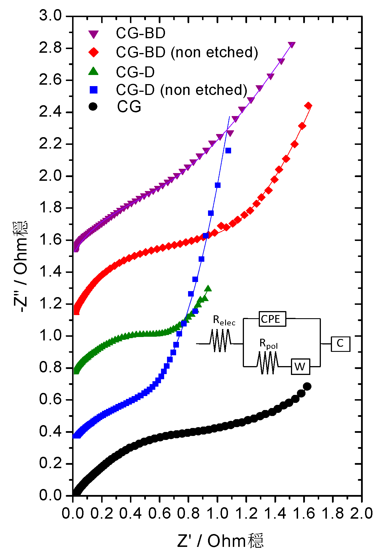
The Nyquist plots recorded for the aerogels are shown in
Figure 9; these profiles are largely affected by the polycrystalline and highly porous texture of the electrodes; therefore, numerical fitting to an equivalent circuit is required for quantitative discussion (see inset in
Figure 9). The different components of the equivalent circuit used are the electrolyte solution resistance (R
el), the Warburg impedance (W), a constant phase element (CPE), a capacitor (C), and the polarization resistance (R
pol). The latter parameter is mainly responsible for the resistance to the ionic migration into the porous structure. The highest R
pol value was recorded for the CG sample (1.52 Ohm·g), while an effective decrease in the resistance was observed for the samples still containing diatomite. Thus, R
pol values of 0.68 Ohm·g and 1.1 Ohm·g were calculated before etching off the diatomite additive in samples CG-D and CG-DB, respectively. A slight increase in the resistance was observed for sample CG-D (0.74 Ohm·g) after the removal of the additive; we attribute this behavior to an improvement in the accessibility of ions to pores of small sizes (microporosity) that would remain blocked by the additive. For sample CG-DB, the R
pol value (0.90 Ohm·g) was slightly better than that of its corresponding non-etched counterpart, pointing out the beneficial effect of carbon black, as a result of enhanced conductivity and the presence of pores of wider sizes (
Figure 5).
Figure 9.
Nyquist plots derived from impedance spectra recorded for the diatomite treated carbon aerogels and carbon aerogel used as a blank sample (for clarity purposes, the curves have been shifted by 0.4 units in the ordinate axis). Inset: Equivalent circuit applied to the fitting of the impedance spectra.
This was further supported by the electrical conductivity values measured on the monoliths, which are mainly controlled by the presence of carbon black; after etching off the diatomite (insulator), the electrodes presented conductivity values close to those reported for carbon aerogels prepared without siliceous additive, although differences also depend on the formulations (
cf. N-doped aerogels display higher conductivity than RF ones) [
21,
26,
28]. Values ranged from 2.1 mS/cm for sample CG; 2.2 mS/cm for sample CG-D and 4.3 mS/cm for sample CG-DB.


 ,
, 


