1. Introduction
Present-day sophisticated electronics have created significant challenges to their thermal management due to their robust performance improvement, size compactness, and working conditions. During operation, the associated heat flux increases exponentially in modern-day electronics. For example, a heat flux level of 120–150 W/cm
2 has already been reached in some electronics applications and the trend is perpetually rocketing [
1], while, on the contrary, traditional thermal management systems are continuously facing difficulties to meet this growing challenge and, in some circumstances, they have proven inadequate. It should be noted that the electronic component’s lifetime and reliability are highly vulnerable to their operating temperature, as well as temperature uniformity. As a result, highly efficient thermal management systems are in high demand to meet this growing challenge.
Several emerging technologies show the potential to become high heat flux electronics cooling systems: innovation of several types of heat sinks, thermoelectric coolers, forced air systems and fans, nano-fluids, microchannels, nanoporous membrane tubes, impingement and spray cooling, etc. [
2,
3,
4,
5,
6,
7,
8]. Narcy et al. [
9] proposed a novel type of two-phase heat spreader for electronics cooling applications, which is based on a flat confined thermosiphon system. The study primarily investigated its thermal performance and flow visualization. Based on the findings, it appears that confined fluid inside the heat spreader increases the degree of freedom of the heat source’s location and induces a confined boiling phenomenon. Furthermore, robust coupling between boiling mechanisms and condensation was observed and the system’s sensitivity to inclination angle is relatively low. Likewise, a miniature vapor compression refrigeration system was deployed for electronics cooling, where the evaporator consisted of a micro-channel heat sink [
10]. The refrigeration system’s purpose was to control and maintain the heat source surface temperature within a suitable range. The study concluded that the surface temperature of the heater could decrease if the compressor speed increases. However, it will also decrease the coefficient of performance (COP). A detail of the current state of the art, involving traditional and emerging electronics cooling methods, and related coolants, can be found in work conducted by Murshed and Castro [
11].
Another potential trend over the past few decades is the application of oscillatory flow in electronics thermal management systems that facilitates enhancing heat transfer capability compared with unidirectional flow. For instance, Mackley and Stonestreet [
12] showed experimentally that the oscillatory flow has a significant heat transfer enhancement capability in the periodically baffled tube compared to unidirectional flow. Within the study, different important heat transfer parameters were studied: Prandtl (Pr) numbers, penetration length, Womersley, etc. Moreover, a correlation for Nusselt Number and dynamic pressure of the flow was established based on the experimental results. The Nusselt number, as well as the instantaneous and time-average bulk temperature, showed that when the Prandtl number and penetration length increased, the overall convective heat transfer increased. Similarly, heat transfer phenomena for oscillatory flow were examined in a circular tube by Bouvier et al. [
13]. The heat conduction inverse method, and the local heat transfer, was characterized in their study. To gauge the onset of turbulence in the oscillatory flow, Zhao and Cheng [
14] presented a correlation in terms of kinetic Reynolds number and amplitude of the flow. The effect of frictional loss and transition to turbulence were also investigated for their oscillatory airflow. In literature, computational fluid dynamics widespread use has also been observed to study the flow and heat transfer phenomena [
15,
16]. The application of a flow pulsation waveform in a mesochannel for heat transfer was inspected by McEvoy et al. [
17] and a recent review regarding mechanically driven oscillatory flow can be found in the literature [
18].
Along with other promising technologies, Reciprocating-Mechanism Driven Heat Loop (RMDHL) is an excellent addition to the current state of the art in high heat flux electronics cooling systems. The RMDHL [
19,
20,
21] is a liquid-based cooling device that works by changing the flow direction between the heat sink and the heat source on a continual basis within the device. Compared to typical Dynamic Pump-Driven Heat Loops (DPDHL), the RMDHL provides a superior cooling performance. Several studies have already shown its advantage over conventional systems. For instance, Cao and Gao [
22] introduced a solenoid-driven Reciprocating-Mechanism to produce necessary oscillatory flow. It was intended for two-phase cooling applications, which can handle a high heat flux of up to 300 W/cm
2. In addition to the RMDHL superior heat transfer performance, the flow mechanism could also suppress the cavitation problem that might occur within conventional pumps. The similar superior performance of the RMDHL over the DPDHL system, in terms of surface temperature uniformity and heat transfer, was also observed in the investigation of Soleimanikutanaei et al. [
23]. The research developed a numerical model to study the reciprocating motion flow for the desired frequency. For a given mass flow rate, the average surface temperature in the RMDHL was substantially less than the DPDHL. Popoola et al. [
24] analyzed the heat transfer phenomena for an RMDHL loop, both experimentally and numerically. Their reciprocating flow was driven via piston-cylinder-mechanism and the constant heat flux was applied to the evaporator. Along with the investigation of heat transfer phenomena, they established a Nusselt number correlation for the loop cycle. The accuracy of different turbulence models during the analysis of the RMDHL loop performance was also investigated and summarized [
25]. The research findings show that for the calculation of the average cold plate temperature, the standard k-ɛ Model is more accurate, whereas, for the cold plate surface temperature, the RNG k-ɛ Model shows more accuracy. In similar fashion, Sert and Beskok [
26] numerically examined reciprocating flow in a two-dimensional channel under forced convection conditions. They determined the heat transfer rate in terms of the penetration length, Womersley (α) number, Prandtl (Pr) number, bulk temperature distributions, and the instantaneous and time-averaged surface temperature. Furthermore, they developed a comparison between the reciprocating flow and unidirectional flows.
The present study is another advancement on RMDHL and maintains significance, as well as novelty, in several ways. Firstly, the above-cited studies regarding the RMDHL loop are mostly concentrated on reciprocating flow in a duct, not at the system level, whereas the present design is implemented in the system-level application and is essential for its successful demonstration. Secondly, previous studies focused more on thermal performance. In contrast, the present study investigates in more detail the effect of different important design parameters that should be considered during its design stages. Thirdly, the current loop has been tested for a wide range of heat transfer distances and rates, as opposed to previous studies, with limited heat transfer distances and rates. Finally, analytical models related to the reciprocating loop design criteria and performance have been developed, and the model’s results have also been compared with the available experimental results. Therefore, combining all these together justifies the significance and novelty of the current work.
Here,
Section 2 presents the experimental setup. The results and discussion are presented in
Section 3, followed by effective heat transfer conductance and correlation in
Section 3.1.
Section 4 presents the critical displacement volume of the RMDHL, followed by the conclusion in
Section 5.
2. Experimental Setup
A bellows-type reciprocating heat transfer device was constructed on the basis of Cao et al. [
27]. The device is designed to handle high heat transfer rates with a single-phase flow. The setup, CAD drawing of the test rig, the schematic of the cooling loop, and the locations of the thermocouples (102 to 107) are shown in
Figure 1a–c.
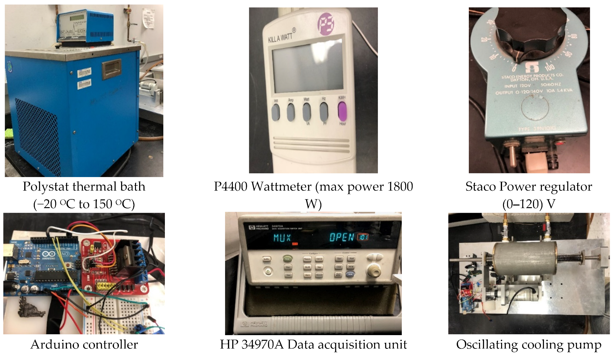
The reciprocating driver includes an actuator-driven piston in conjunction with two bellows for sealing purposes. The inner diameter of the bellows is 2.70 cm with 50 turns. They are attached to the driver mechanism at each end of the chamber to facilitate the reciprocating motion of the piston while maintaining the chamber in a hermetic condition. An Arduino controls the driving mechanism and the Progressive Automations Linear Actuator, while a force of 150 lbs drives the piston. A circuit board has been used to regulate the actuator DC power supply. The setup uses a flexible heater KH-108 Omega lux flexible heater, 100 W (manufactured by Omega Engineering, Stamford, CT, USA), and a Polystat thermal bath with a temperature range from −20 °C to 150 °C that maintains a constant temperature for the cooling water. The Staco power regulator in conjunction with a P4400 Wattmeter (manufactured by Prodigit Electronics, New Taipei City, Taiwan) connected to the flexible heater was employed to generate and measure the heat input in the evaporator section. An HP 34970A Data Acquisition unit (manufactured by Bell Electronics NW, Inc., Renton, WA, USA) records the temperatures for each given point.
Appendix A summarized each component’s details for the present experiment. Copper tubing has been selected for heat loop having an outer diameter of 14.32 mm and a wall thickness of 0.889 mm. Low thermal conductivity woven fiberglass tape was used for the insulation purpose to prevent heat loss from the experimental setup.
When the thermal bath reached the required cooling temperature, the operation of the linear actuator was initiated while the heat input to the evaporator heater gradually ramped to a test level. After the heat loop reached a steady-state condition, the temperatures were recorded on the PC using the Agilent BenchLink Data Logger software (Version 4.3, Agilent technologies, Santa Clara, CA, USA). It should be noted that water has been used to transport heat within the pipe as it has widespread applications for cooling purpose [
28,
29]. However, the measured temperature in the thermocouple represents the surface temperature of the pipe, not the water inside. The reciprocating frequency, driver stroke or amplitude of the reciprocating flow inside the cooling loop, heat transfer rate, power input to the actuator, and the inlet cooling temperature of the condenser water were also recorded.
3. Results and Discussion
To investigate the effect of different operational parameters on RMDHL performance, the average temperature values in the condenser, adiabatic, and evaporator sections were calculated by using thermocouples:
T4 (condenser) = 0.5 × (T107 + T108)
T3 (adiabatic section) = 0.5 × (T105 + T106)
T2 (evaporator section) = 0.5 × (T103 + T104)
T1 = T102
where T102 to T108 are the temperatures recorded by the thermocouples located in the test rig, according to
Figure 1c. In this experiment, the experimental uncertainty sources are only the instruments. The scanning thermocouple thermometer has an accuracy of ±0.1% of reading ±0.4 °C and the power meter has an accuracy of ±(1% reading + 5 digits). Therefore, the maximum uncertainty for the temperature and heating power measurement would be 1.0% and 2%, respectively.
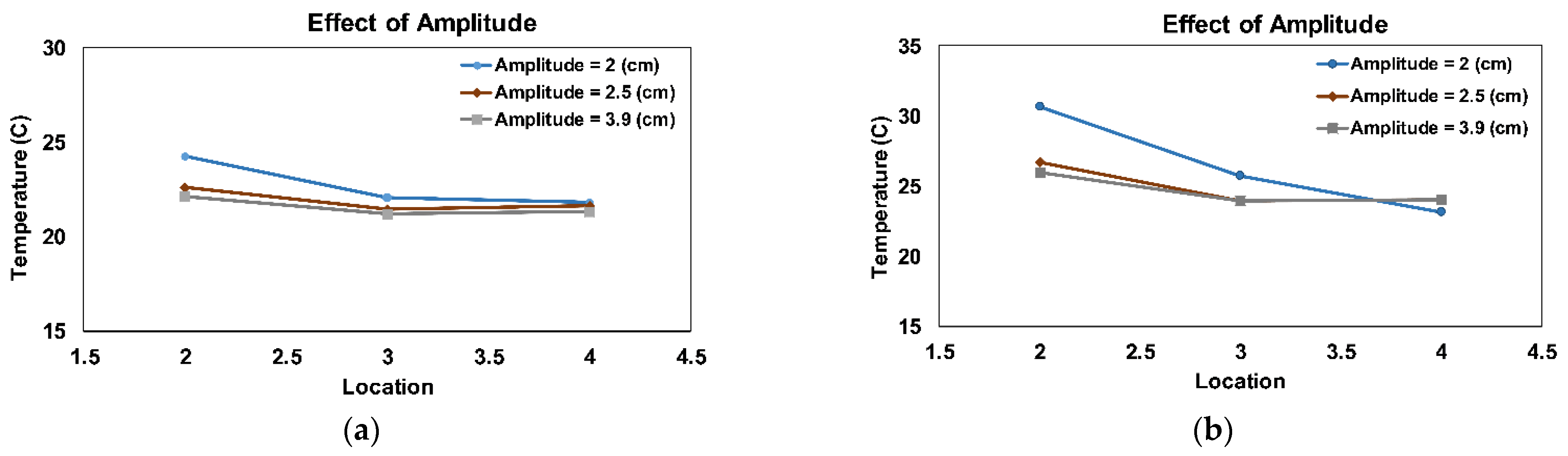
It should be noted that the experiment was conducted for a wide range of variations for each input parameter, so that it can determine the significance of each parameter’s effect. During the experiment, the input power in the evaporator section varied from 20 W to 90 W, the amplitude varied from 2 cm to 3.9 cm, and the reciprocation amplitude indicates the displacement of the piston from its initial position in centimeters. Similarly, the reciprocating frequency varied from 13 s/cycle to 20 s/cycle and the cooling water temperature varied from 15 °C to 30 °C. However, for brevity, the important finding of the study has been plotted and presented within a couple of cases. For instance, the effect of the reciprocating amplitude on the temperature distribution in the RMDHL is shown in
Figure 2, under the conditions of input power = 20 W and 60 W, reciprocating frequency in terms of a second per reciprocating cycle = 20 s/cycle, and cooling-water inlet temperature = 20 °C.
Figure 2a,b shows that as the amplitude of the reciprocating flow increases, the loop surface temperature decreases, and the temperature uniformity along the loop improves. Notably, the loop surface temperature improvement is more obvious for amplitude 2.0 to 2.5 than for amplitude 3.9 cm at a higher power input. It is believed that the ideal cooling condition for the loop performance would exist when the heated fluid in the hot region could fully move to the cold region. If the reciprocating amplitude is less than the minimum requirement, the heated water could not effectively reach the loop cold region. As a result, the heat transfer rate would decrease, and the temperature gradient would increase significantly.
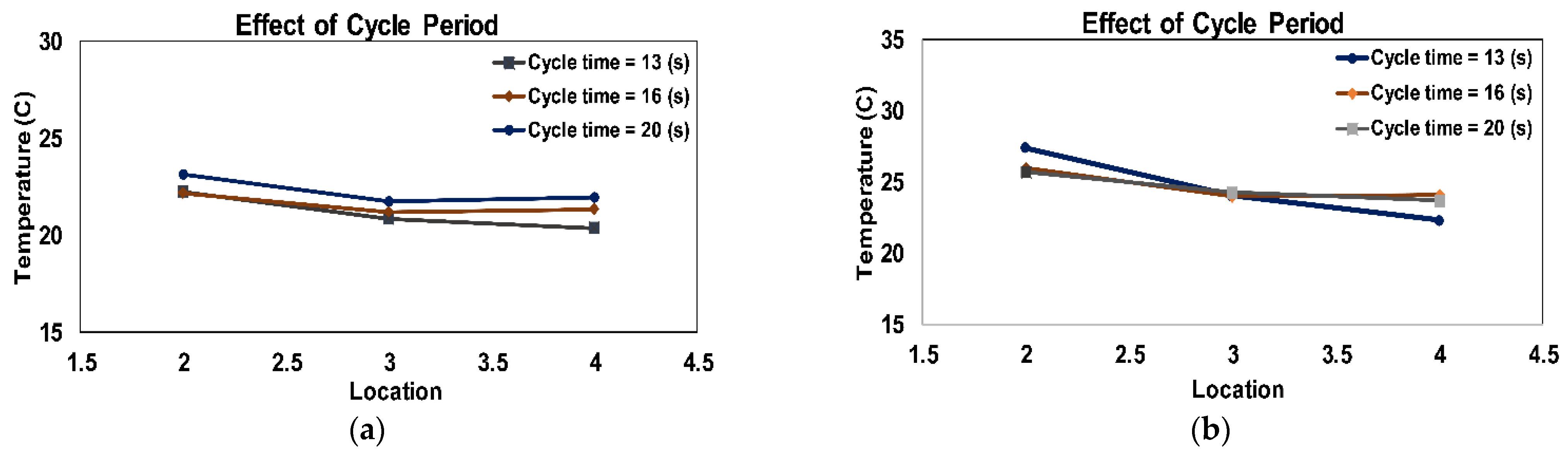
Similarly, the effect of reciprocating frequency in terms of time per cycle on the temperature distribution along the cooling loop is shown in
Figure 3, when input powers are 20 W and 60 W, amplitude is 3.9 cm, and cooling water temperature is 20 °C. As can be seen from the figure, both a higher frequency of 13 s/cycle and a lower frequency of 20 s/cycle result in a higher temperature gradient along the loop, while a moderate frequency of 16 s/cycle produces a much more uniform temperature. In contrast to the effect of the amplitude, a higher frequency may not necessarily improve the temperature uniformity, although the temperature in the evaporator section may be lower. Furthermore, the temperature in the adiabatic section appears to be insensitive to the reciprocating frequency. Therefore, it is noticeable that the effect of amplitude is much more significant compared with the reciprocating frequency on the RMDHL performance.
Figure 4 illustrates the effect of the cooling water inlet temperature on the surface temperature of the RMDHL, for a temperature range of 15 °C to 30 °C. The input powers are 20 W and 60 W, and the frequency and amplitude, respectively, are 16 s/cycle and 2.5 cm. Like many other heat transfer devices, the cooling water temperature controls the temperature level of the loop, and a lower cooling water temperature produces a lower loop temperature level.
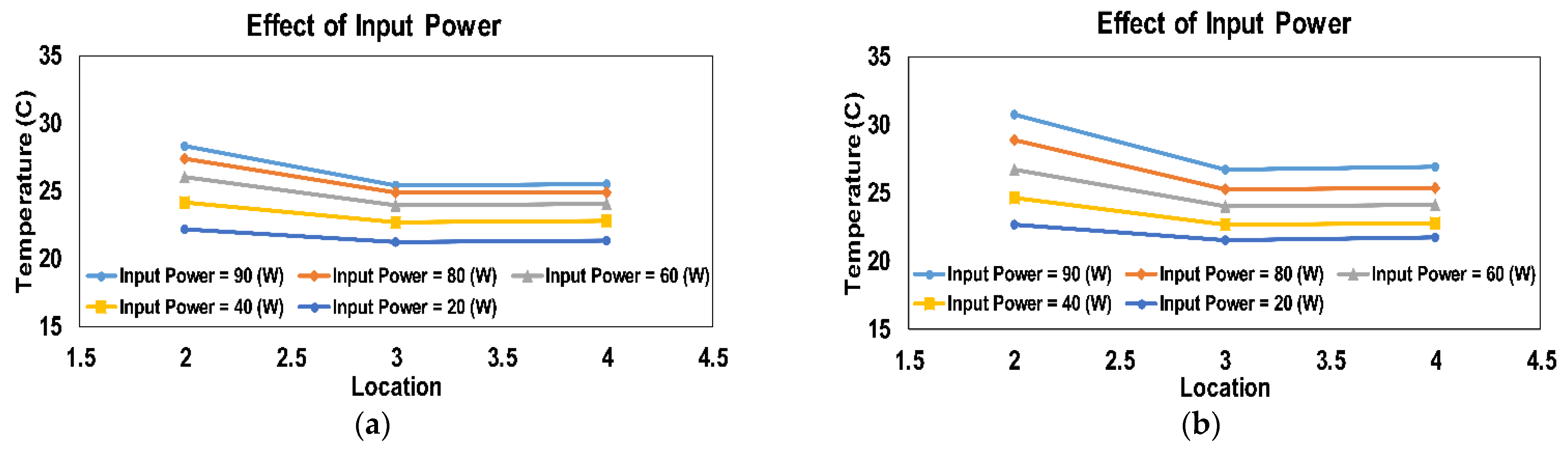
The effect of the input power of the flexible heater on the temperature distribution along the RMDHL is shown in
Figure 5, under the conditions of constant cooling water temperature = 20 °C, cycle frequency = 16 s/cycle, and amplitude = 2.5 cm and 3.9 cm. As expected, a higher heat input would increase both the temperature level and temperature gradient along the loop, where the temperature gradient is primarily caused by heat transfer in the evaporator section. It is obvious from
Figure 5 that rising amplitude improves the temperature gradient along the loop for each power input. The temperature gradient from the adiabatic section to the condenser section is almost zero, as evidenced by the almost identical readings of T4 and T3, due to the effective water cooling in the condenser section.
3.1. Effective Heat Transfer Conductance and Correlation
The system’s effective heat transfer conductance—an important design parameter—has also been investigated. It is widely used to gauge the performance of heat pipes and can be evaluated according to the following relationship:
where
represents the heat input,
L represents the effective distance between evaporative and condensation sections,
is the temperature difference between the evaporative section and condensation section, and
represents the loop tube cross-section area, which is calculated based on the outer diameter.
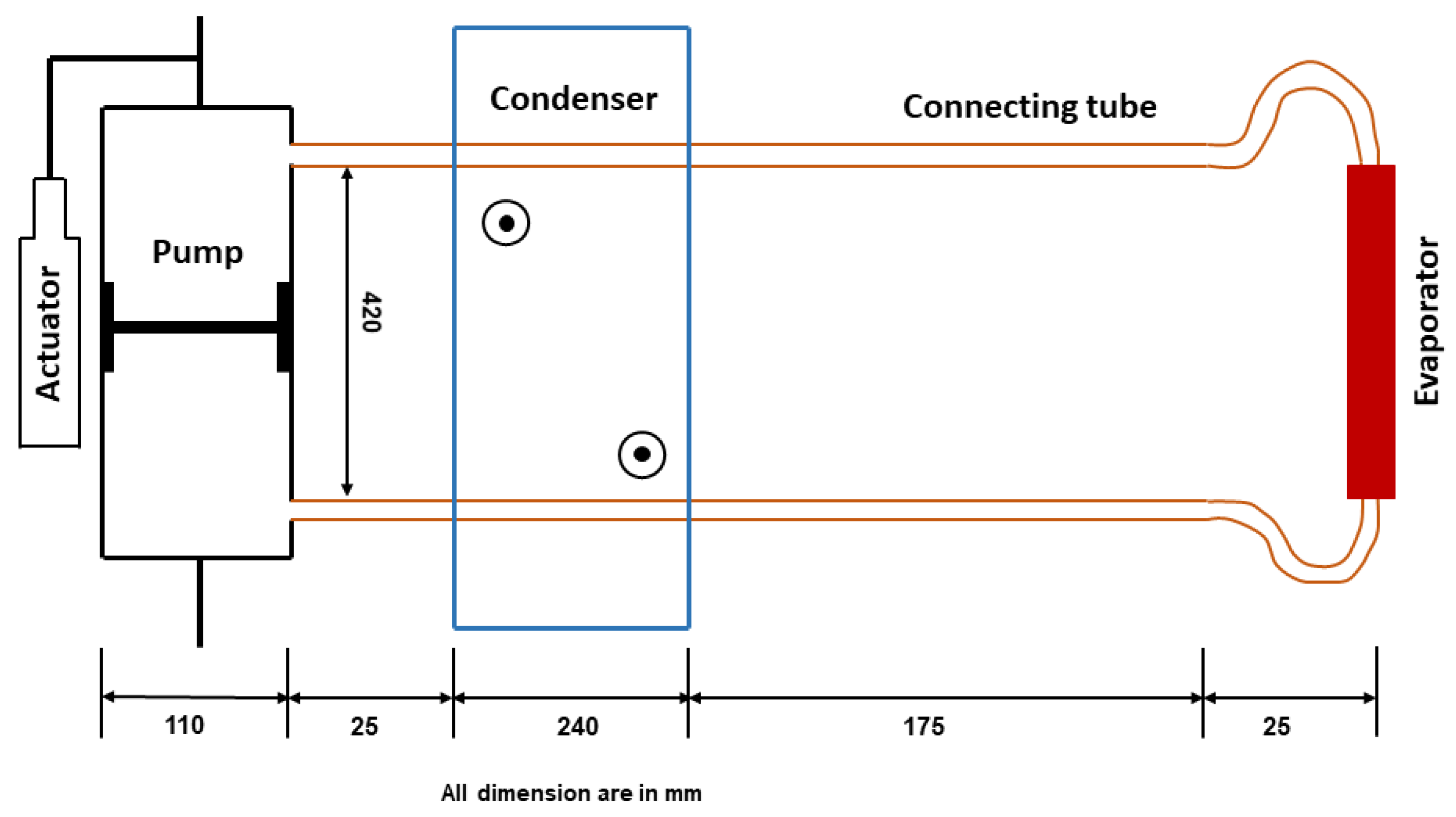
Figure 6 represents a schematic diagram of the present experimental setup with associated necessary dimensions.
A sample calculation for 40 W heat input in the evaporative section is shown as follows:
If the copper thermal conductivity is considered to be
W/(m·K) the dimensionless effective heat transfer conductance would be for the 40 W heat input.
It seems that the RMDHL in this study is a very effective heat transfer device—the thermal conductance of RMDHL is more than 200 times higher than the copper thermal conductance at 40 W power input. For general application, a correlation for dimensionless effective heat transfer conductance has been established, in terms of flow kinematic Reynolds number
and non-dimensional amplitude
. Both the dimensionless parameters are specified by Cooper and Yang [
30], herein the kinematic Reynolds number (also known as the Womersley number (
W0)) is calculated using the oscillation or reciprocating frequency (
ω).
The
is essentially a dimensionless reciprocating frequency of the reciprocating driver, and
A0 is a dimensionless reciprocating amplitude of the driver. The reciprocating frequency
and reciprocating amplitude
X would determine the operational condition of the reciprocating driver, which, in turn, determines the performance of the reciprocating-flow loop. Since the effective heat transfer conductance
is a major performance gauge of a reciprocating loop device, it is naturally a function of Re and
A0, in terms of dimensionless variables. Therefore, with the help of regression analysis, the following dimensionless effective heat transfer conductance correlation has been established for the present RMDHL system:
Additionally, the present correlation accuracy is assessed and illustrated in
Figure 7, comparing this with the experimental data. It should be noted that a reference conductivity Copper (
k), the value of 400 W/m·K, has been adopted in the dimensionless effective heat conductance calculation. Most of the experimental data fall within or around +20% and −20% of the correlation predictions; an estimated error of about 20% for the current correlation.
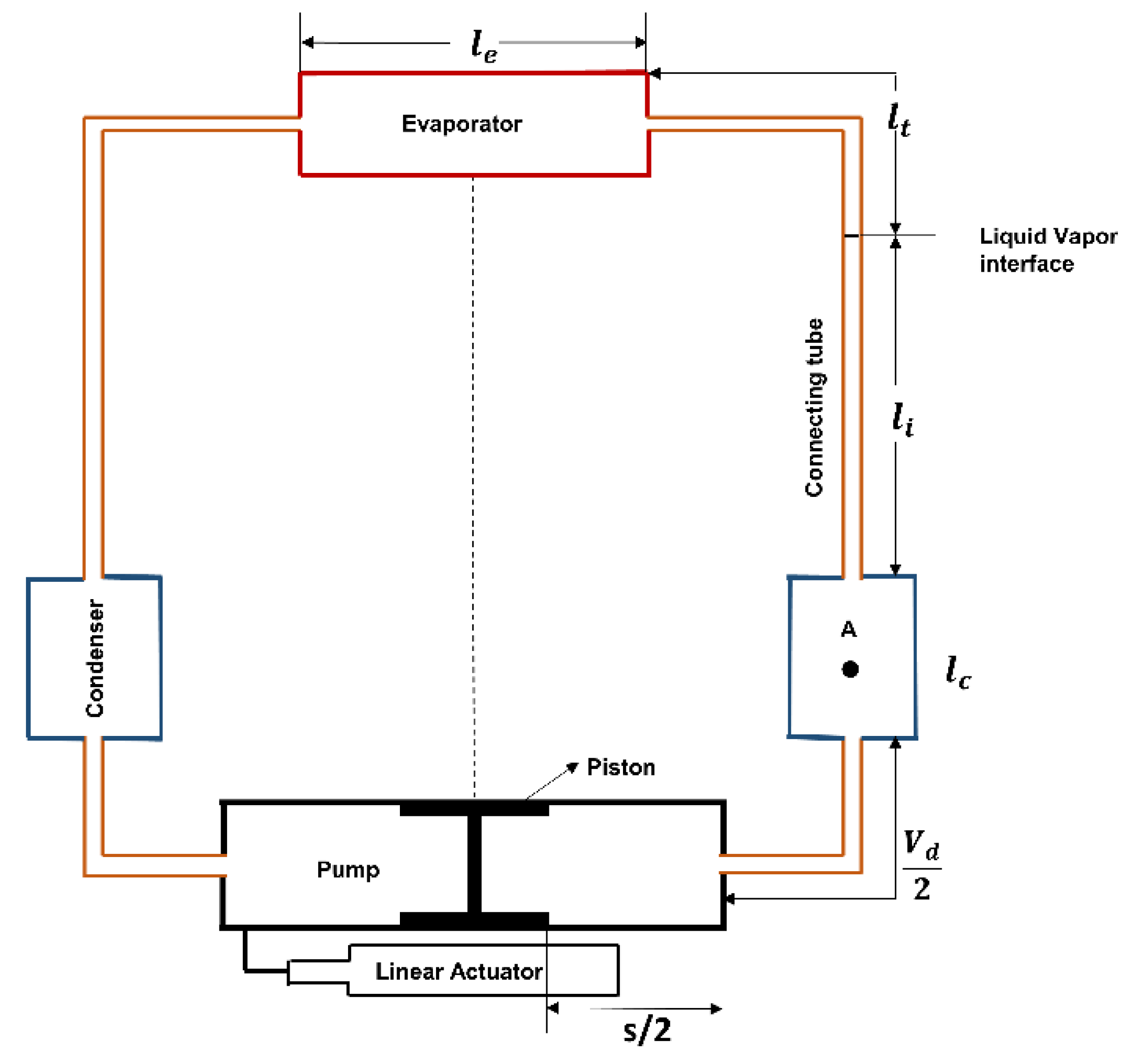
4. Critical Displacement Volume of the RMDHL
For successful deployment of the RMDHL in thermal management applications, the driver should work in such a way that the condenser section liquid must reach the evaporator section. As a result, a sufficiently large working fluid displacement volume (driven by the piston) is critical to ensure the adequate liquid supply between the condenser and evaporator section (cold plate) of the cooling loop. However, a larger displacement volume demands a larger size of the liquid reservoir, subsequently, a larger cooling system. Therefore, a tradeoff must be made, not only to ensure a sufficient displacement volume, but also to maintain a reasonable cooling size. The present study wishes to address this requirement and establish a relationship for the critical displacement volume requirements for future system design.
Figure 8 shows a schematic of the cooling loop.
Due to the system nature, the cooling loop maintains condenser sections on both sides of the reciprocating driver and evaporator section. Hence, the cooling system can be considered as symmetric, with respect to the middle line between the reservoir and evaporator section. Therefore, the analysis of half of the loop is adequate enough to derive the critical displacement volume requirement. Regarding the right half of the loop, different section lengths and areas are termed via
and
a, respectively, with their associated section’s subscriptions (Condenser (
c), evaporator (
e), connecting tube (
t)). Likewise,
Vd/2 indicates total interior volume from the piston right dead end to the condenser section,
ap represents the piston cross-sectional area, and
s is defined as the stroke of the reciprocating driver. In the course of the operation, the vapor produced in the evaporator section moves the liquid in the direction of the condenser section with a liquid–vapor interface (
Figure 8). The thin liquid layers may have been generated on the evaporator’s internal surface. However, it is ignored in the present analysis. Thus, the critical working condition is thought to be achieved when the condenser’s center liquid, designated by A, can just reach or cross the evaporator midsection during piston movement, from the middle to right dead center. Mathematically, it can be written as follows:
Simplifying Equation (5), we have:
The above equation can be rewritten as:
The right-hand side of Equation (7) represents the total interior volume between the condenser center and evaporator center. It is considered as an important geometric parameter for its successful deployment. If the total interior volume is termed as effective displacement volume, afterward:
Equation (7) can be expressed as follows:
To achieve the system maximum potential, Equation (9) specifies that,
apS must be equal to or greater than
. It specifies that the piston’s liquid displacement volume must be equal to or larger than the cooling loop’s effective displacement volume. For our present experiment, the minimum stroke used is about 2 cm, and cross-section of the pipe is uniform:
Therefore, the present experiment satisfies Equation (9).
The derived relation for the critical displacement volume, Equation (9), is also employed for three prior successful loop designs on RMDHL, and the outcomes are presented in
Table 1, including the result of the present study. Since all four designed loops worked properly and satisfied Equation (9), thus, Equation (9) can be used as a design criterium of RMDHLs. It should be noted that the referenced studies in
Table 1 are all prior studies on RMDHLs.


