
Effect of the Fire Modelling on the Structural Temperature Evolution Using Advanced Calculation Models
by
Donatella de Silva
1,*, 
Samuele Sassi
2,
Gabriella De Rosa
1,
Giorgio Corbella
2 and
Emidio Nigro
1 1
Department of Structures for Engineering and Architecture, University of Naples Federico II, Via Claudio 21, 80125 Naples, Italy
2
FSC Engineering Srl, Fire & Structure Consulting, Via Vincenzo Monti 56, 20123 Milan, Italy
*
Author to whom correspondence should be addressed.
Fire 2023, 6(3), 91; https://doi.org/10.3390/fire6030091
Submission received: 31 January 2023
/
Revised: 23 February 2023
/
Accepted: 24 February 2023
/
Published: 27 February 2023
(This article belongs to the Section Mathematical Modelling and Numerical Simulation of Combustion and Fire)
Abstract
:The main objective of this study is to compare the results in terms of gas temperature and structural elements temperature, using different localized fire models. In particular, with reference to an open car park fire, the simplified Hasemi localized fire model was firstly used for assessing the steel temperature of a typological steel-concrete beam. In the second step, the computational fluid dynamics (CFD) models were applied, also varying the geometry of the fire source; in the first case a 3D flame was considered, in the second case a flat flame source was modelled. The latter represented one of the main research novelties of this work. All the analyses were carried out without and with the activation of a sprinkler system, simulated by varying the Heat Release Rate curve, according to the Italian national fire technical code. The main results show that there was a significant effect of the fire model, indeed the Hasemi model generally overestimated the steel element temperature. Moreover, an effect of fire source modelling was observed, with greater temperature for a 3D fire source modelling in the case of no sprinkler activation. In all the analyses, to consider the sprinkler system leaded to a beneficial effect on temperature.
1. Introduction
For the designing and assessment of the structural fire resistance, the EN 1991-1-2 (2002) [1] defines five performance levels, based on the building importance. In order to satisfy the fixed performance level, different design solutions based on prescriptive or performance-based approaches can be adopted. The main difference between the two approaches is that the first one is based on standard fire resistance tests or empirical calculation methods, using nominal fire curves. In particular, the code provides three types of conventional fire curves (standard ISO834 [2], hydrocarbon, and external nominal curve), selected according to the nature of the combustible materials in the compartment. On the other hand, the performance-based approach considers the complexity of structures and the inter-relationship between the various fire safety measures and systems, using specific natural fire curves, generally obtained by advanced thermo-fluid-dynamic analyses.
The first step of the performance design approach consists in the thermal input evaluation through the choice of the design fire scenarios, which represents qualitative description of the fire evolution, based on real fire key aspects (e.g., compartment dimension, ventilation, fire loads...). The choice of fire model is a fundamental aspect for many uses, such as open car parks, which are increasing, due to the growing number of vehicles in recent decades. The most effective way, in terms of performance, cost and simplicity to build these open car parks involves the use of a composite steel-concrete structure. During a fire, the flash-over condition is rarely reached in an open compartment, so the localized fires should be considered, which leads to the heating some elements. For the structural fire design, different models can be used, such as simplified ones or advanced numerical modelling. The EN 1991-1-2 (2002) [1] suggests different simple models for localized fires, e.g., the models proposed by Heskestad [3], Hasemi [4] and the LOCAFI [5] models, which can be applied in specific situations, and advanced numerical modelling as the computational fluid dynamics (CDF). As also said before, to assess the fire safety of an open car parks requires an accurate representation of the fire events. The modelling of the fire source is essential to better understand the evolution of the gas temperatures of a car park and for the following structural verification phases. In addition, the choice of an appropriate heat release rate, HRR, for vehicles and a realistic fire propagation are necessary to a reliable fire safety design of structural elements. In this context, the fire source modelling can influence the evolution of the gas temperature both in terms of maximum temperature θMAX reached, of heating rate and of time at which θMAX is reached. These aspects can influence not only the structural fire checks, but also the verification of human life safety and their evacuation. Indeed, steel car parks show high vulnerability mainly to the maximum temperatures of the fire, due to the steel mechanical properties degradation caused by the heating. While the concrete elements are also influenced by the time of exposure to the fire. In fact, as stated in a previous research [6], the concrete structure is sensitive not only to the temperature peak reached during the fire, but also to the duration of each temperature level. So, to assess the structural elements exposed to fire is essential to create a reliable model that returns the gas temperatures closest to reality. Furthermore, a more accurate evaluation of the structural element temperature can lead to different indirect actions inside the structure, according to the reduction in material stiffness.
Several were carried out on the different fire modelling, focusing on the open car park. Yan et al. [7] proposed a numerical study on the thermal exposure on steel framing members in open car park fire, comparing the steel temperatures computed by the coupling of computational fluid dynamics and finite element modelling, and by analytical models from the Eurocodes. In addition, the influence of galvanization on the steel temperature evolution is assessed. Results show that temperatures in unprotected beams and columns are influenced by the section geometry, car fire scenario, modelling approach, and use of galvanization. Regarding the different models, CFD-FEM (CFD: computational fluid dynamics, FEM: finite-element method) coupled models predict lower temperatures than the Hasemi model, because the latter conservatively assumes that the fire flame continuously touches the ceiling. Nigro et al., [8], investigated the behaviour of open and closed car parks, under different fire scenarios, applying the aspects of the Fire Safety Engineering (FSE) for the structural safety checks in case of fire, with reference to Italian and European standards. However, very few paper investigated the source fire modelling and its effects on the structural element temperatures. About this topic, Wang et al. [9] highlighted the influence of using different fuel geometrical shapes on flame extension, temperature distributions and gas species concentrations during different tunnel fire development phases. The results have shown that the use of the geometrical shapes causes significant differences in flame extension lengths during the fully developed fire phase. Another relevant aspect in the case of open car park can be represented by the wind effect, that can influence the ventilation effect; this aspect was investigated by Ghodrat et al. [10].
Khan et al. [11] studied the differences between conventional localized fires and the localized burning in large compartments, introducing the concept of semi-confined fire and considering the compartment effects into localized fire models. Hidalgo et al. [12] considered the transition of fire modes in a full-scale fire test carried out in an open-plan industrial building. Three different fire modes were identified including a traveling fire, a growing fire, and a fully developed fire, by the ratio between the flame front velocity and burnout front velocity. Nadjai et al. [13] conducted large scale fire tests, investigating the development of a traveling fire in open structures in the frame of the European RFCS-TRAFIR project and concluded that the positioning of the traveling fire band and the ceiling height directly influenced the temperatures reached in the surrounding structures. However, no researcher investigated how the fire source influences the temperature gas evolution and therefore the temperature inside the structural element. In addition, limited research investigated the fire response of car park structures.So, the main objective of this study is to perform several fire analyses, comparing the results in terms of gas temperature and structural elements temperature, with different localised fire models. The main novelty consists in studying the effect of the fire source modelling in CFD analyses, changing its geometrical and combustion properties.
2. Description of the Analysed Structure
2.1. Geometry and Main Structural Features
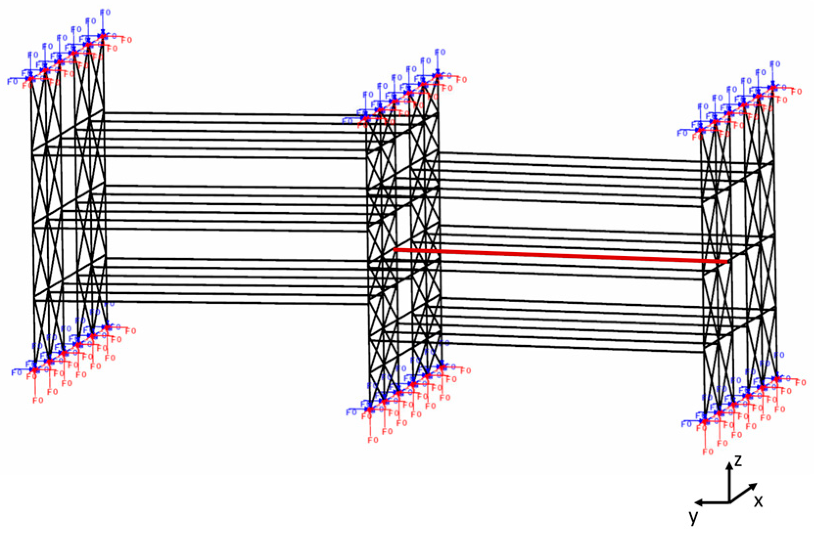
To carry out the study of the gas temperatures reached in a typical steel-concrete composite beam under an open car park fire, a general medium-sized multi-story open car park (see the Figure 1) was used.
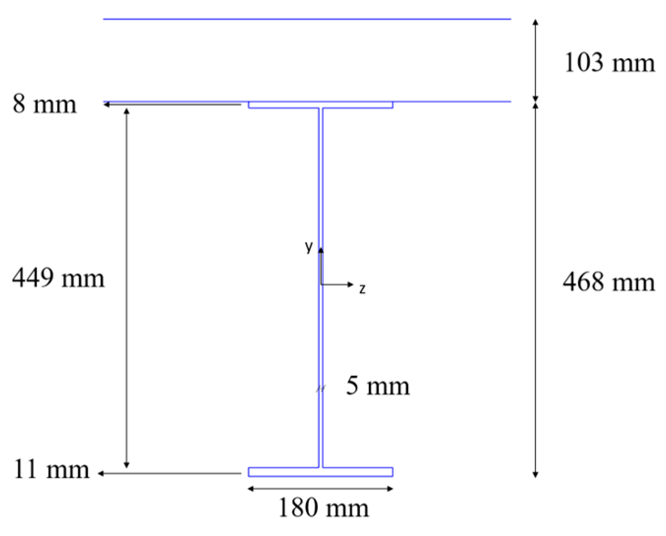
All the evaluations were conducted both considering the effect of the active fire protection systems as sprinkler and without it. While no passive fire protection was applied to the structure. The structure consists of steel beam members and concrete flat slabs. The distance between the floor and the bottom part of the ceiling is about 2.70 m. The floor plan of the car park is 16 m × 60 m, with 5 m × 2.5 m standard parking bays. In particular, the analysed sub-structure was composed of six levels, as shown in the Figure 1. At the base of substructure, fixed joints were considered, while at top columns the horizontal displacement and the rotation were fixed. Axial external forces were applied on the top columns to take into account the whole structure effect [14]. In the Figure 1, the red line represents the beam analysed for the temperature monitoring. The structural element consisted of steel-concrete composite beam SPR468 with a concrete slabs 0.103 m thick. The beams are spaced 2.5 m to each other, and their length is about 16 m, which represents a common length for the primary beams in an open car park. The dimensions of the SPR468 profile are shown in the Figure 2.
The concrete was class C40/50 and the steel was S355. The analysed structure was designed according to the EN 1994 1-1 (2004) [15], while the mechanical and thermal properties of the composite steel-concrete beam were considered variable with temperature, according to the EN 1994 1-2 (2005) [16], as also suggested in [17,18].
2.2. Fire Scenarios
The fire scenarios are influenced by the geometry compartments and by their natural ventilation conditions. In the typical open car parks, the layout, the combustible, geometrical characteristics, and the ventilation condition can be assumed standard and so it’s possible to consider a limited number of design fire scenarios [1]. To describe a fire scenario an essential input data is the Heat Release Rate (HRR) curve. The HRR curve gives information about the energy released during the fire. In particular, the HRR can be evaluated in two different ways; the first one is an analytical estimation according to the Annex E of EN 1991 1-2 (2002) [1]. The HRR curves can be also obtained by mean cone calorimeter experimental tests, as also described in the following.
The definition of the data input used for the evaluation of the design fire scenarios was one of the goals of the “Demonstration of Real Fire Tests in Car Parks and High Buildings” research project, developed between 1998 and 2000 by CITCM (France), PROFIL-ARBED Recherches (Luxembourg) and TNO (Netherlands) [19], considered in this paper.
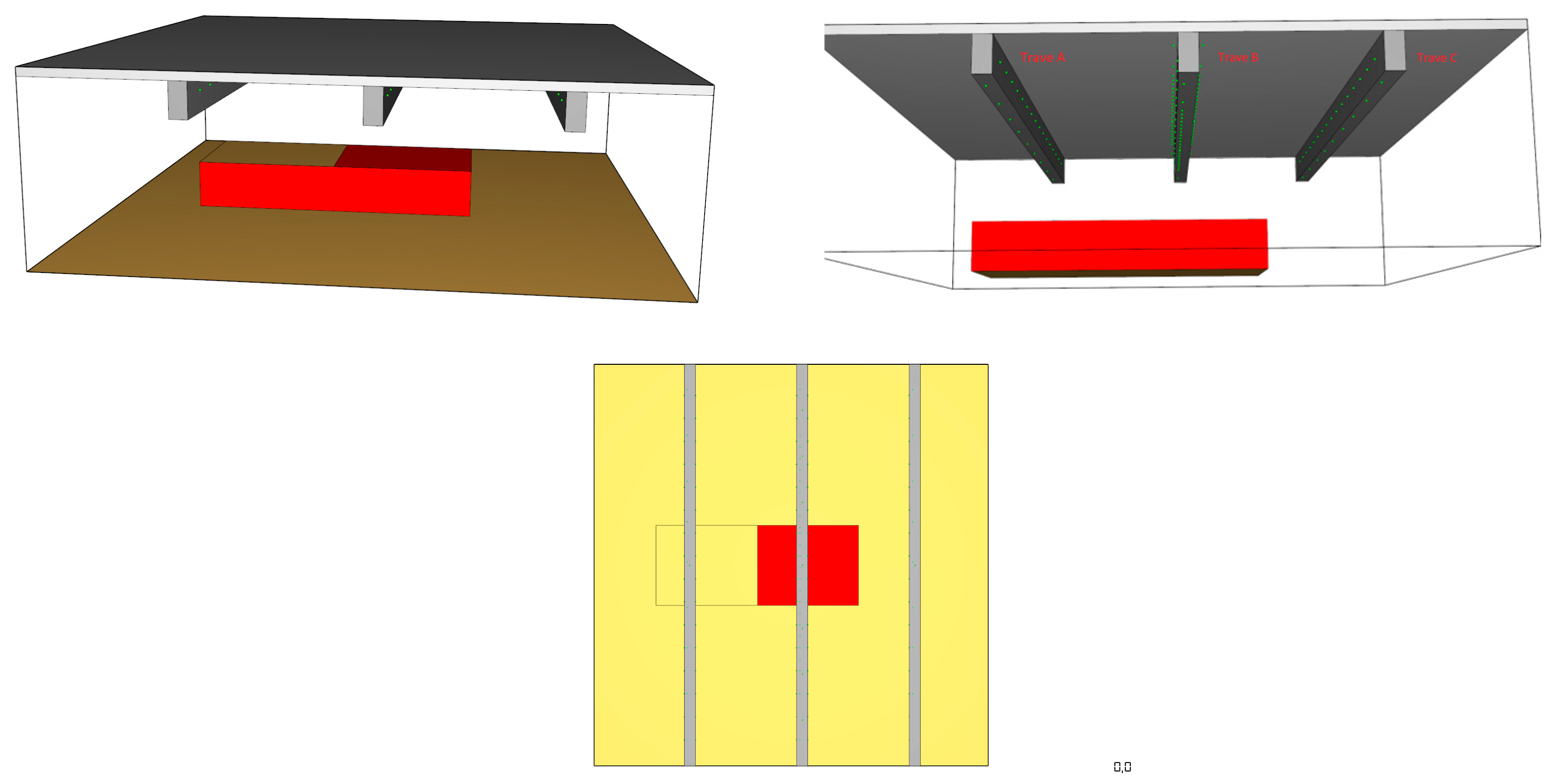
In [19], a classification of cars was conducted according to their calorific value. Then, experimental measurements of the HRR of cars were carried out, which gave the possibility of identifying the HRR curve of a class 3 car representative of medium category sedans. The fire propagation between cars in a typical parking configuration of a ventilated car park were experimentally evaluated, identifying the heat release curve representative of the fire involving three class 3 cars. Starting from this preliminary work, the fire scenario considered in this study was a fire located below the mid-span of the 16 m composite steel-concrete beam (see the Figure 3a,b).
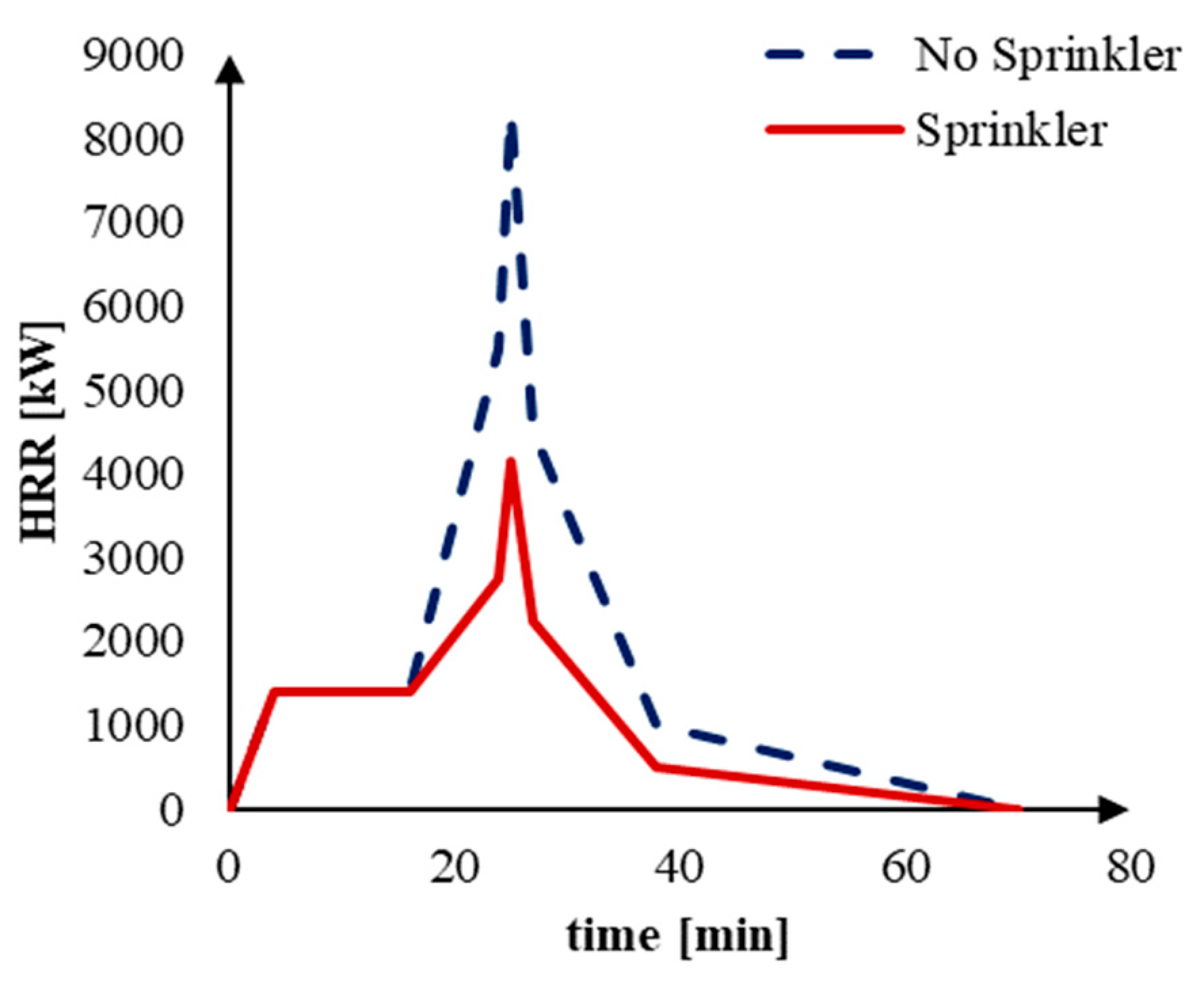
To characterize the fire and the gas temperatures, the HRR curve given by the Italian technical national Fire Code [20], which is the same contained in the CTICM recommendation [19], was used. As also said before, the fire analyses were carried out also considering the scenario with the sprinkler system activation, for which the HHR curve was reduced by 50%, according to Italian technical national Fire Code about the car parks fire safety design [20] (see Figure 4).
3. Description of Modelling Approach
During a fire in opened compartments, the flash-over condition is rarely reached, so the localized fires should be considered, heating only some structural elements. In the case of a localized fire, the temperatures in the flame, in the smoke and in the surrounding gas are not uniform, unlike in the generalized fire, in which the gas temperature can be considered constant with a good approximation. The thermal action of a localized fire on the structural elements can be evaluated through different models, e.g., the Heskestad model [3] or Hasemi one [4] proposed in the Annex C of the EN 1991-1-2 (2002) [1]. The difference between the two approaches regards the relative height of the flame to the ceiling. In addition, the LOCAFI [5] simplified localised fire model was proposed by the EN 1991-1-2 (2002) [1] for calculating the radiative heat flux received by a vertical member not engulfed in the fire area (e.g., a column). This last method was directly applied in this work, as localized fire scenarios related to the main beam were considered (see Section 2.2). These models were implemented also in the thermo-mechanical dedicated software SAFIR [21], which is used in this work. In particular, to define the design fire, the equivalent area diameter, the ceiling height and the car heat release rate curve were required. The burning car was modelled by a circular plan area with a 3.25 m diameter. The axis of the localized fire was at the centre of the primary beam, which corresponds to the driving lane. The composite steel-concrete beam temperatures were investigated with the simple models described below, which are valid if the diameter of the fire is limited up to 10 m and HRR of the fire is limited up to 50 MW. Indeed, one of the most relevant advantages of this models is their easy application. Finally, the computational fluid dynamics (CFD) [22] was used for modelling the localised fires. The CFD is an extremely powerful tool, which allows the detailed study of fluid motion in complex geometries.
3.1. Heskestad Model
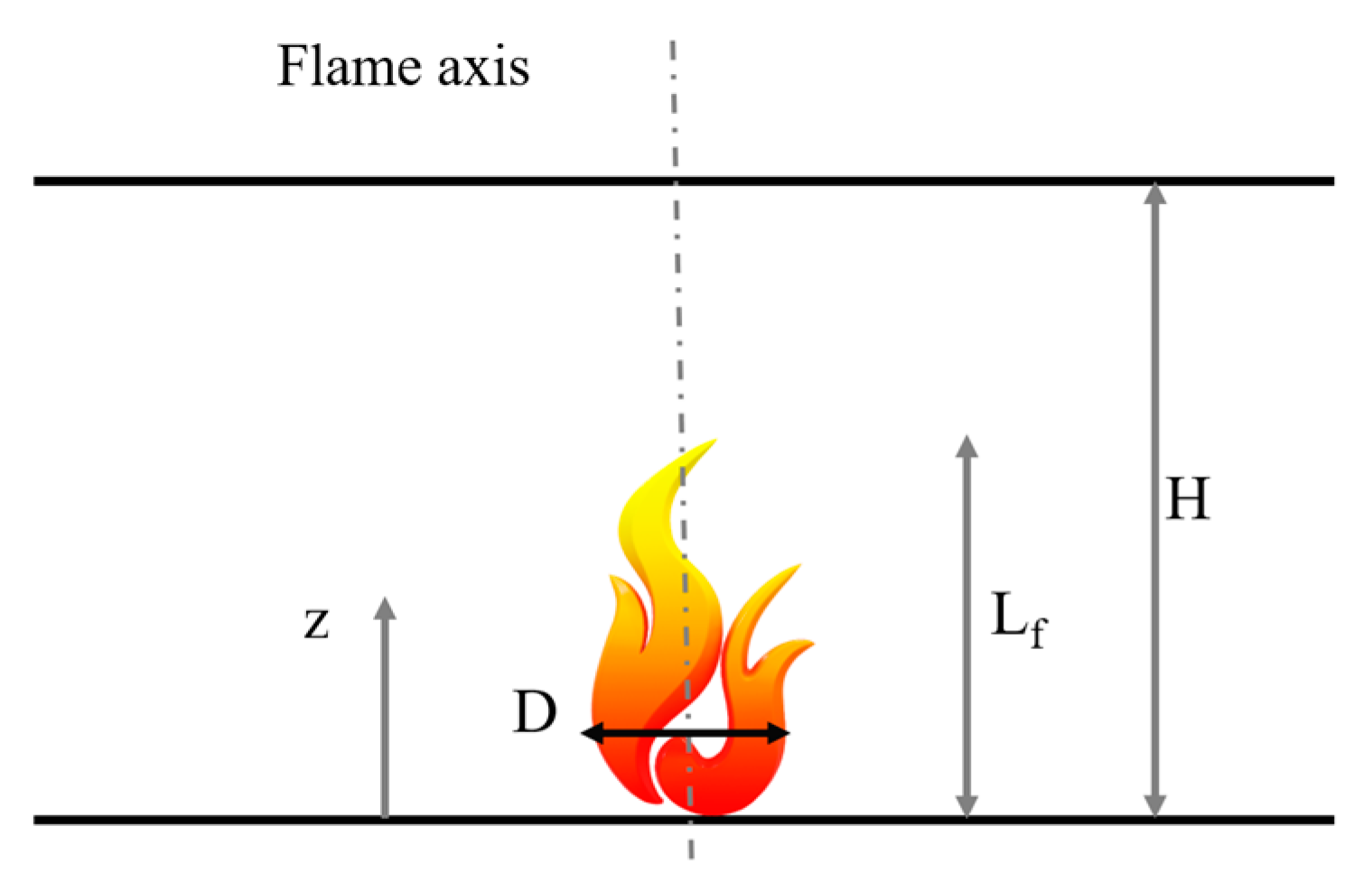
The Heskestad method [3], described in Annex C of the Eurocode EN1991-1-2 (2002) [1], is applicable when the flame is not impacting the ceiling of a compartment (Lf < H, see Figure 5) or for an open-air fire.
The method provides the temperature along the vertical centreline in the fire plume and the heat flux. To calculate the flame length [m] of a localized fire is given by:
Lf = −1.02 Deq + 0.0148 Q2/5
The temperature in the plume θf (°C) along the symmetrical vertical flame axis can be calculated as follows:
where D is the diameter of the fire [m], Q is the heat release rate [W], Qc is the convective part of the heat release rate [W], z is the height along the flame axis [m], H is the distance between the fire source and the ceiling [m]. Instead z0 is the virtual origin of the axis [m] given by:
θf (z) = 20 + 0.25 Qc2/3 (z − z0)−5/3 < 900 °C
z0 = −1.02 D + 0.00524 Q2/5
3.2. Hasemi Model
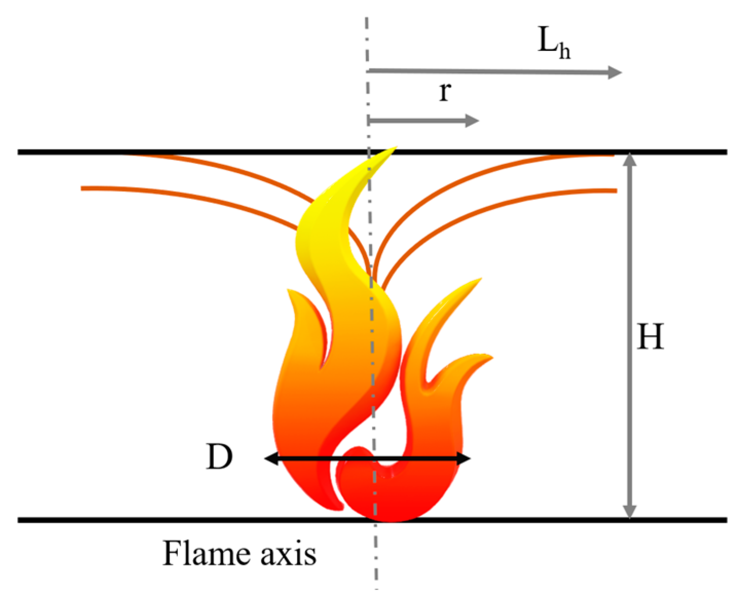
When the flame is impacting the ceiling (Lf < H) the Hasemi model [4] can be used. This method provides the trend of the heat flow impacting the structural elements (see the Figure 6), as a function of the fire position, source fire diameter and the heat release rate over time (HRR) of each type of vehicle (see the Figure 4).
This model is included in EN1991-1-2 (2002) Annex C [1] which provides the following equations for the calculation of the flux:
in Equation (4), y is a non-dimensional parameter given by:
where r is the horizontal distance [m] between the vertical axis of the fire plume and the point along the ceiling where the thermal flux is calculated, H is the distance between the fire source and the ceiling [m] and is the vertical position of the virtual heat source [m]. The net heat flux received by the fire exposed unit surface area at the level of the ceiling is given by:
where is the convection coefficient, is the surface emissivity of the member, is the emissivity of the flame and is the configuration factor, is the Stefan-Boltzmann constant, is the member temperature [°C].
In this work, the Hasemi model was applied directly through SAFIR, which implements the Hasemi methodology for localised fires.
3.3. CFD Models
The previous analyses were carried out also with advanced numerical modelling as the computational fluid dynamics (CDF). Computational fluid dynamics (CFD) is an extremely powerful tool, which allows the detailed study of fluid motion in complex geometries. In the CDF models, to predict the development of the fire, the environment is divided into a large number of elementary volumes in which the balance equations are solved, taking into account the variations that occur in each of them due to the changes in the adjacent ones, acting in an iterative way.
Among the computational fluid dynamics models, the Fire Dynamics Simulator (FDS) software [22], developed by the Fire Research Division at the Building and Fire Research Laboratory (BFRL) of the National Institute of Standards and Technology, is one of the most widespread. FDS is a computational software used to predict and assess the fire evolution. The software numerically solves the Navier-Stokes equations for low-speed flows generated by thermal gradients, considering the smoke/heat transport phenomena typical of fires. To transfer the thermal information from FDS models to finite element analysis, two approaches are generally adopted, the adiabatic surface temperature (AST) and a dedicated FDS-FEM interface. FDS includes a calculation of the adiabatic surface temperature (AST), a quantity that is representative of the heat flux to a solid surface. Following the idea proposed by Ulf Wickström [23], TAST is the surface temperature for which the net heat flux is zero, so it considers that the surface is a perfect insulator. The usefulness of the AST is that it represents an effective exposure temperature that can be passed on to a more detailed model of the solid object. It provides the gas phase thermal boundary condition in a single quantity, and it is not affected by the uncertainty associated with the solid phase heat conduction model within FDS. The second approach is the FDS-FEM interface. In this case a file containing the gas temperatures and radiant intensities at various positions and from different direction in the compartment is created.
FDS software was used also in this work to study the evolution of gas temperature in an open car park. In particular, in order to evaluate the gas temperatures, the FDS-AST approach was used. Two models were developed: (i) the fire without the sprinkler system and (ii) the fire with sprinkler system activation. In addition, the modelling of the fire source was developed according to two different approaches. All the details are described below.
3.3.1. Fuel Source
The fuel source was modelled with two approaches: the 3D car flame simulation (FDS MODEL A) and the flat car flame one (FDS MODEL B). In both cases, the compartment was modelled in FDS using computational domain of 8.75 m × 8.75 m × 2.75 m. The mesh size was 0.125 m in X, Y and Z direction. The steel beam was modelled with its space as 50 cm × 25 cm, with the bottom flange at +2.125 m from the slab domain and +2.625 m from the domain floor. To model the fire action, the pre-set reaction in FDS corresponding to the polyurethane combustion was used. Thermal properties of the concrete-steel beam were considered variable with temperature, according to the EN 1994 1-2 (2005) [16].
3.3.2. 3D Flame Car FDS Simulation
In the 3D flame car simulation (see the Figure 7), the volume of the car was considered equal to 4.5 × 1.75 × 0.75 m3. The HRR/m2 was considered equal to 778 W/m2. The main burning car surfaces were 2 × 4.5 × 0.75 m3, while on the top, a half surface was modelled with 0.5 × 4.5 × 1.75 m3 dimensions.
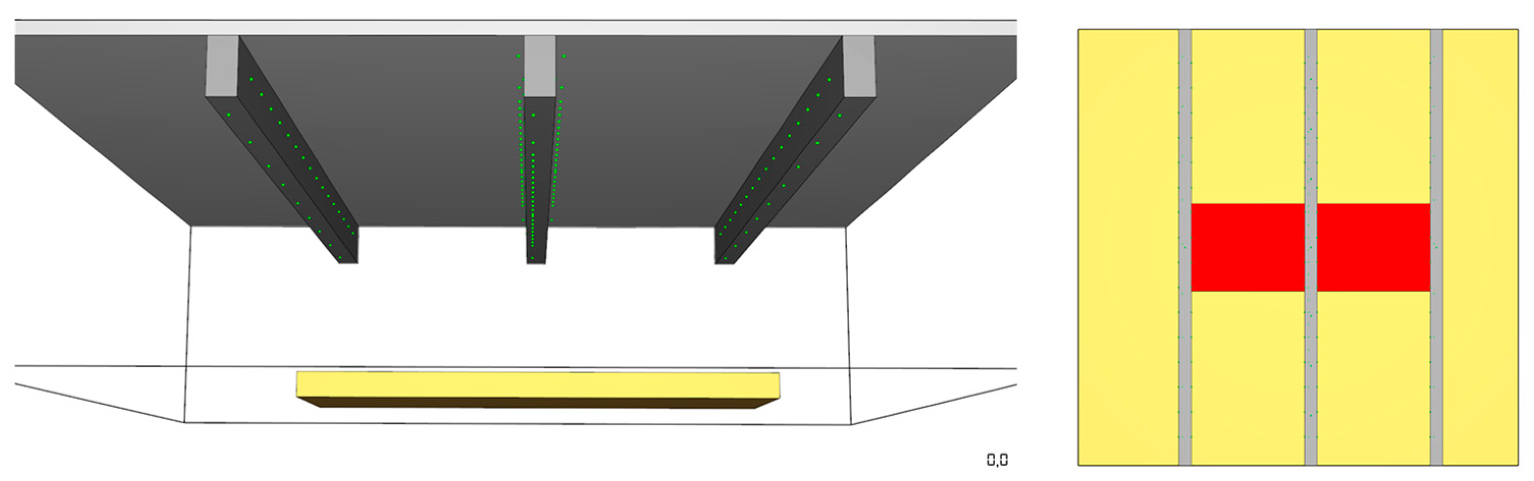
3.3.3. Flat Flame Car FDS Simulation
In the second approach, which considers the flat flame car simulation (shown in the Figure 8), the volume of the car was considered equal to 4.75 × 1.75 × 0.25 m3.
In this case, the HRR/m2 was equal to 1000 W/m2 and the burning car surface was the top surface 4.75 × 1.75 m2.
4. Results and Discussion
To compare both the localised fire models and the FDS fire source modelling effects, a series of thermomechanical analyses were conducted. In addition, the sprinkler effect was considered (see Table 1). All the analyses were performed for 60 min, consistently with the duration of the car heat release rate curve, which represents the input of the fire analyses, as described before.
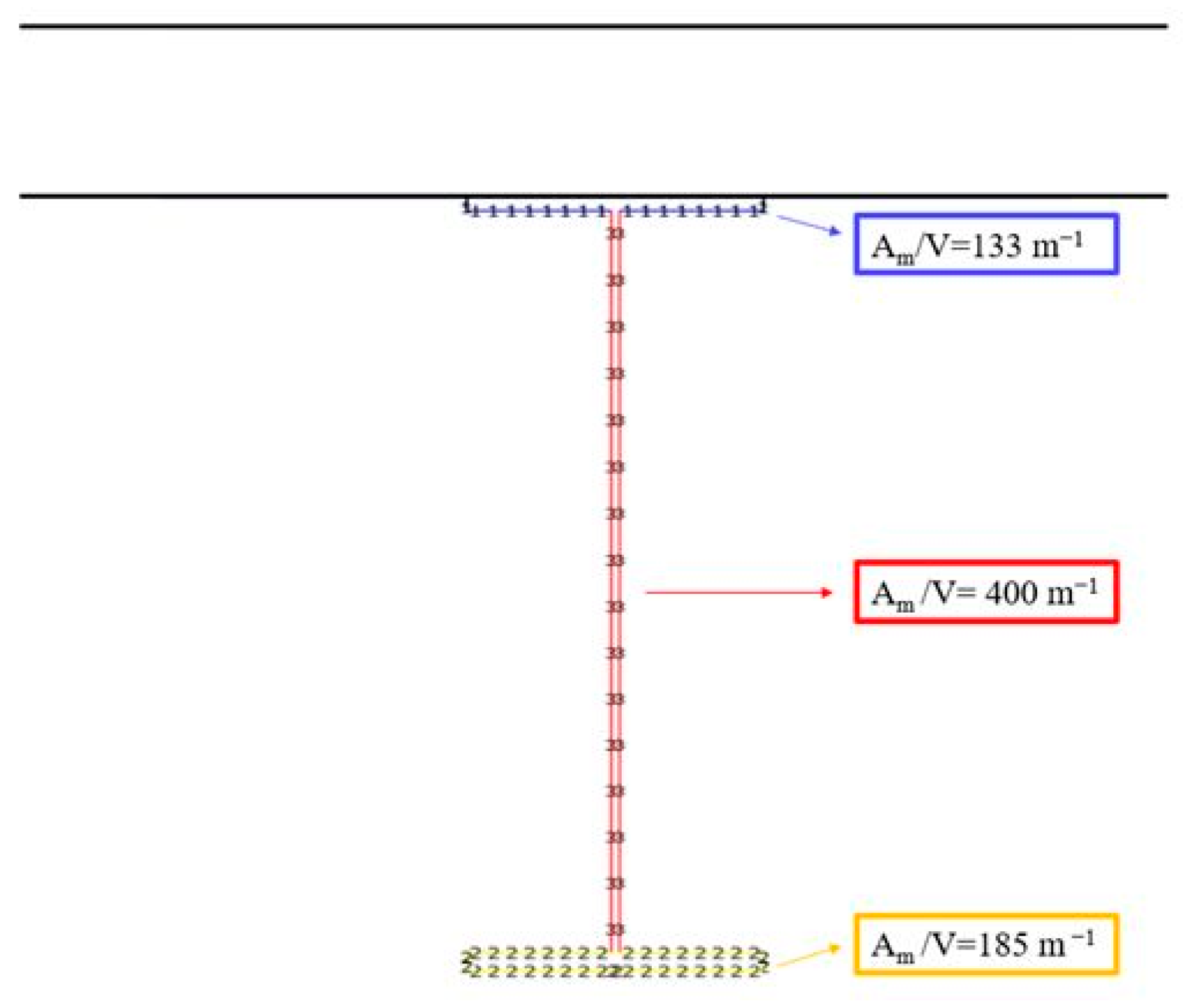
In this section all the results were discussed, both in terms of input fire curves for FDS models and of steel profile temperature for both Hasemi/SAFIR and FDS models. Moreover, for each part of the cross section, the steel temperatures were compared considering the different models. In all the cases the thermal analyses of the steel profile were analysed using the SAFIR software [21]. The FDS-AST temperatures, recorded by thermocouples, were applied to the exposed surfaces of the steel cross section (top flange, web and bottom flange), as shown in the Figure 9.
The rate of increase in temperature of a steel cross-section is determined by the ratio of the heated surface area (Am) to the volume (V). This ratio, (Am/V), has units of m−1 and is known as section factor. The section factor indicates the heating rate of a steel element during a fire; steel members with low section factors will heat up more slowly. In the Figure 9, the section factors Am/V for all the profile parts (top flange web and bottom flange) were shown, emerging that their values are very different. Therefore, the temperature evolution inside these three parts was investigated.
4.1. Comparison between Adiabatic Surface Temperature, Flame Evolution and Gas Temperature in FDS Models
The temperature in the steel profile, which directly influences the fire behaviour of a structure, is clearly linked to the input fire curve. The input temperature in this case were analysed both in terms of ambient temperature and in terms of adiabatic surface temperature (AST), obtained by the FDS simulation described before.
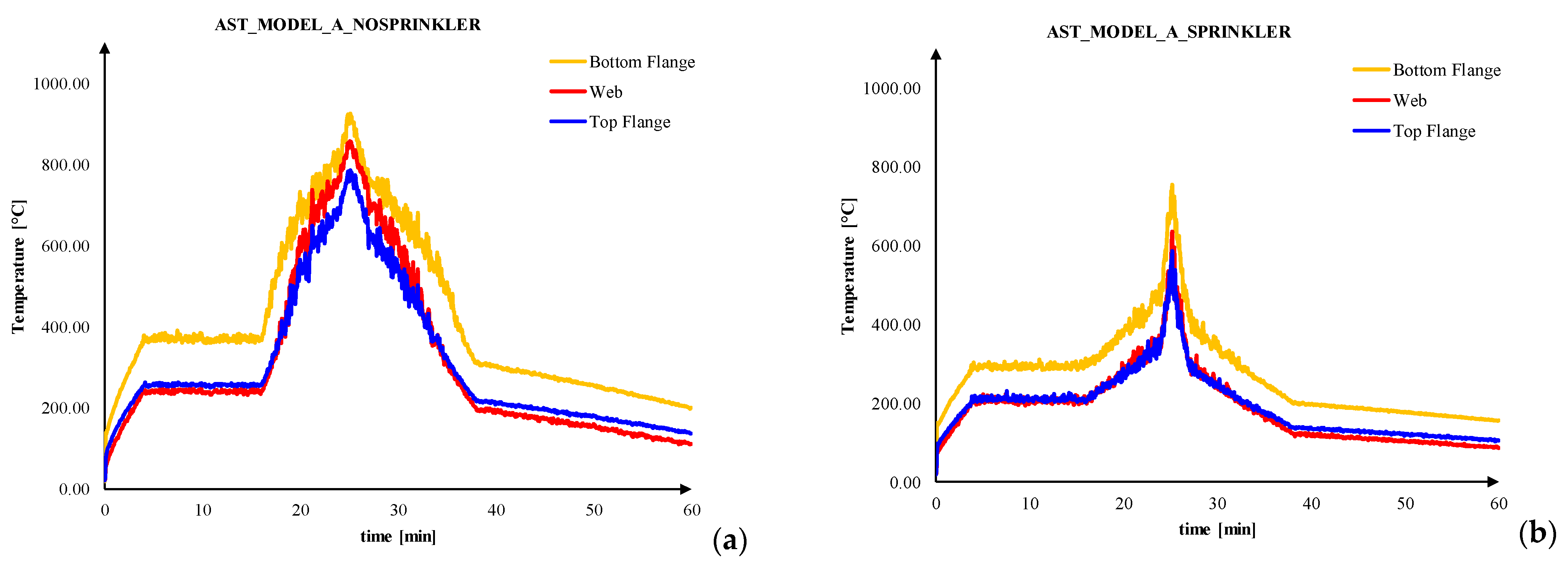
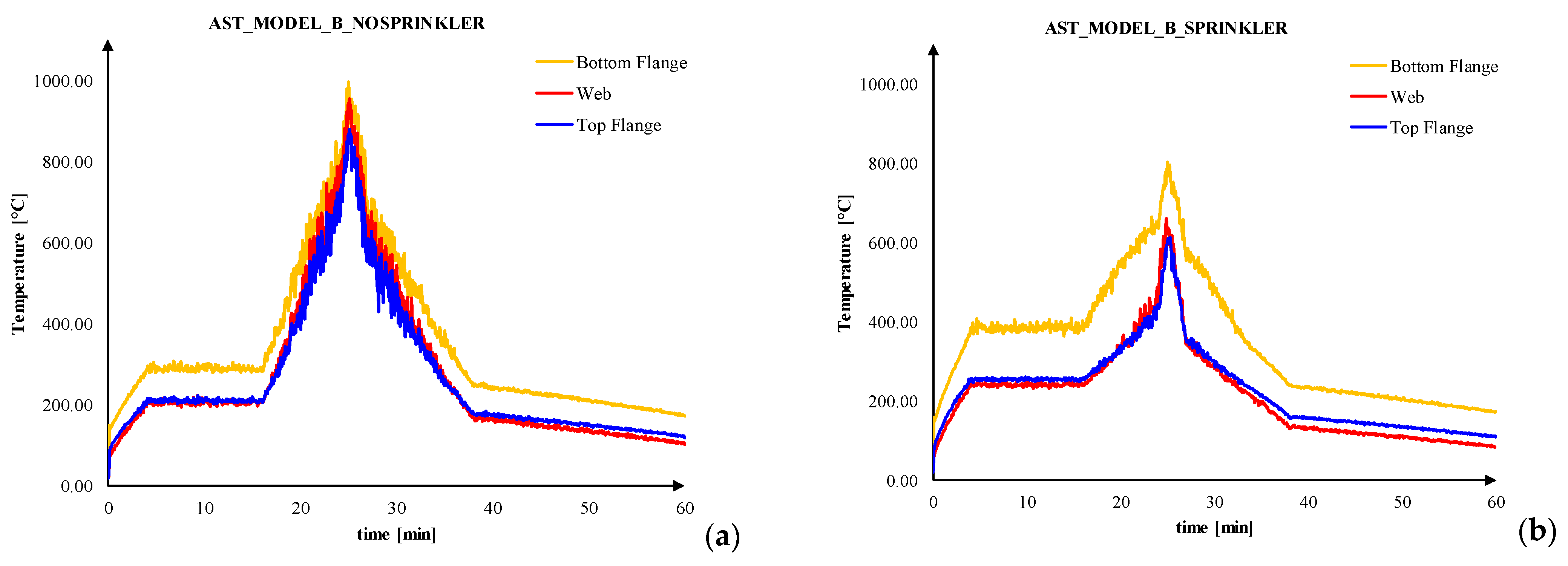
Therefore, a useful comparison is the one between the AST in the case of model_A_nosprinkler, model_A_sprinkler (see Figure 10), model_B_nosprinkler and model_B_sprinkler (see Figure 11), at different compartment locations. In particular, the AST, placed close to the analysed beam, were considered (see). Observing the results some considerations can be stated:
- -
- in all the cases the maximum AST was recorded beside the lower flange, especially in presence of sprinkler, this is due to the greater proximity to the fire source;
- -
- the presence of sprinkler reduced the temperatures;
- -
- the temperatures recorded beside web and top flange are very similar to each other;
- -
- the model with 3D fire source returned higher temperatures than flat flame modelling, in the case of absence of sprinkler.
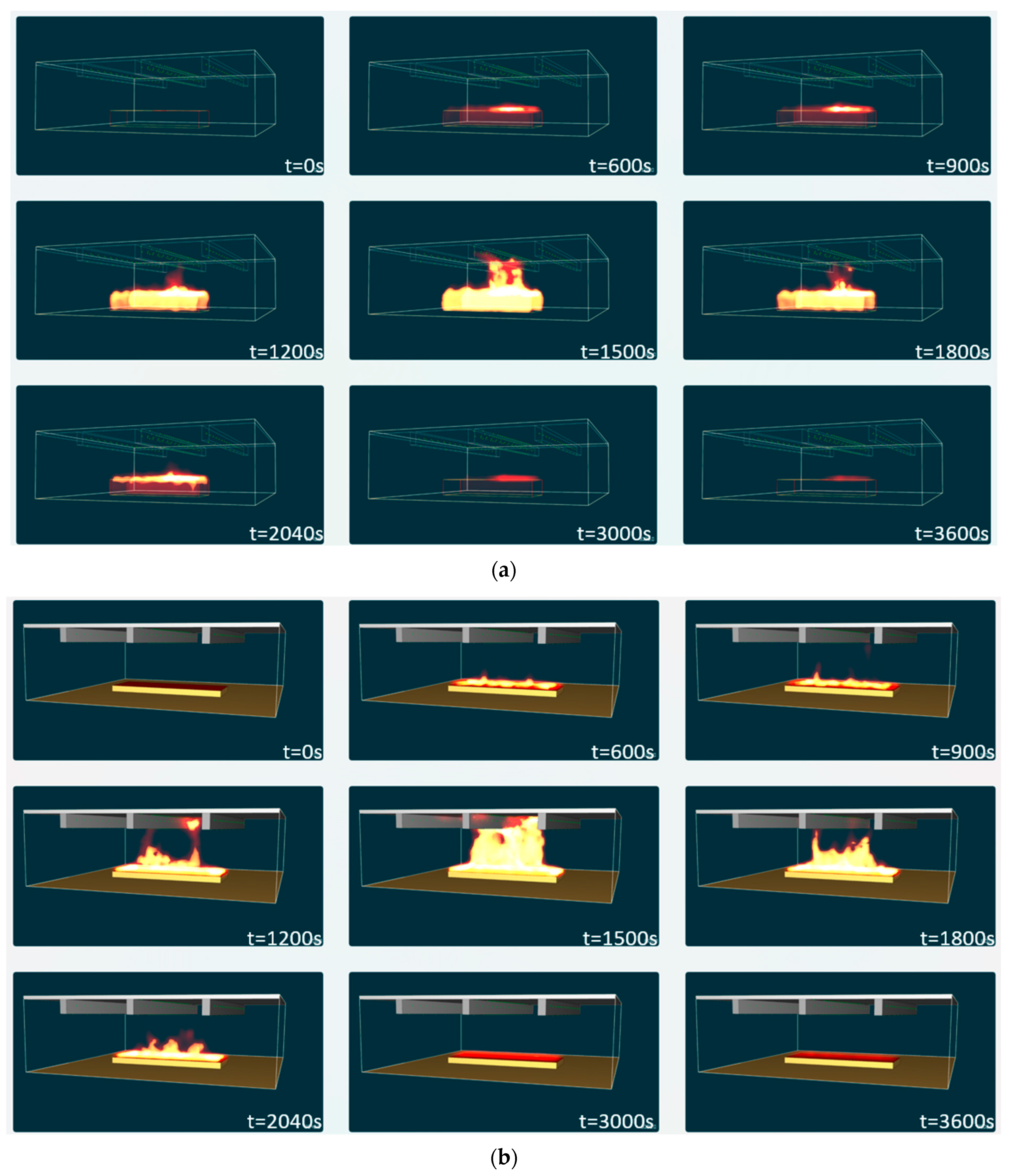
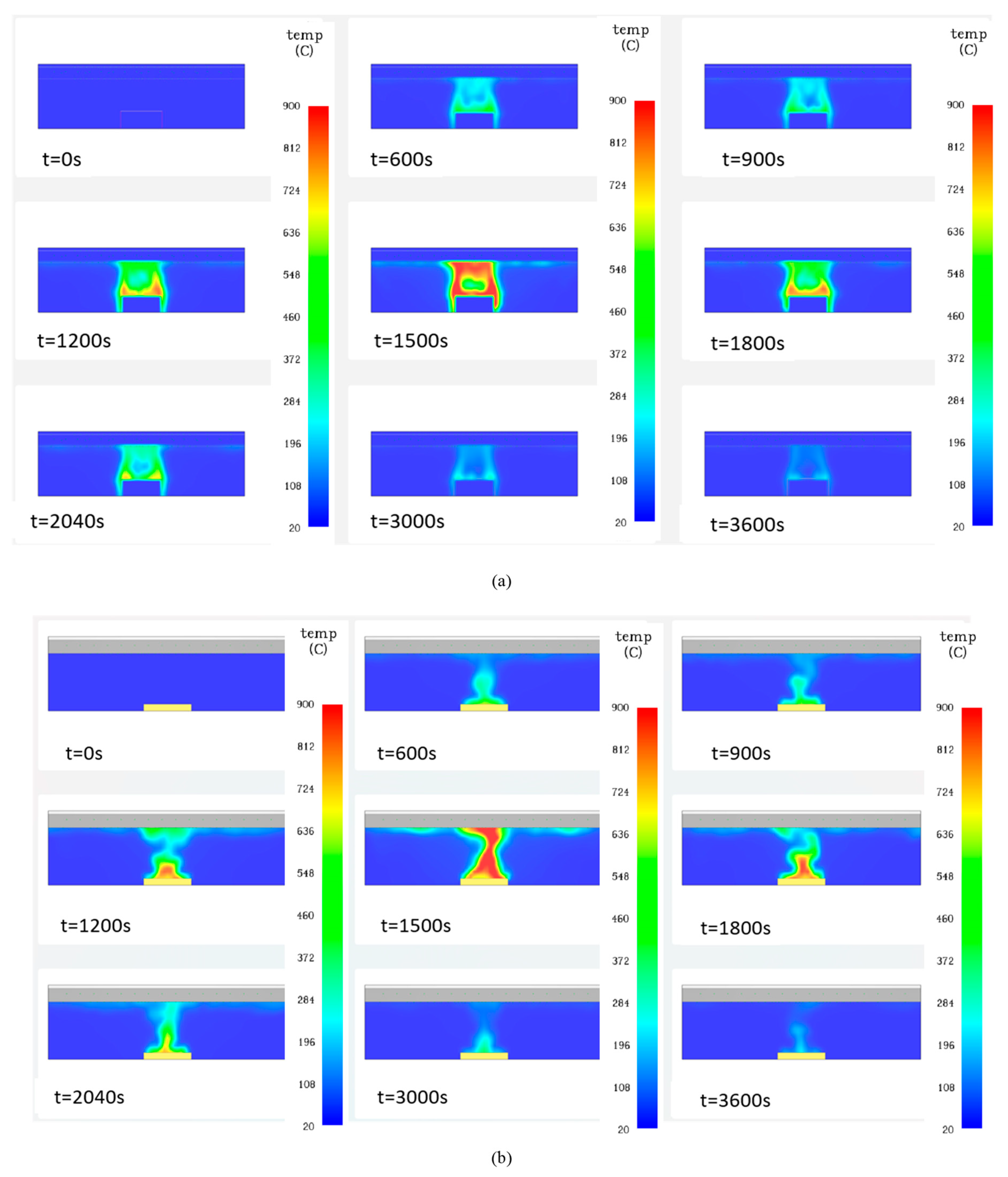
Other general comparisons were made in terms of flame evolution (see the Figure 12) and gas temperature evolutions (see the Figure 13). For brevity reasons, the latter results were reported only for the cases without sprinkler system, as it returns higher temperatures.
The Figure 12 shows the flame evolution for both model_A and model_B at several time steps; the influence of the fire source modelling is very clear, indeed, fixing t = 1500 s time at which the HRR peak is reached, the flame appeared different with a ceiling impact, in the case of model_A, due to the modelling of the real size of the car. The differences in fire source modelling appeared also observing the gas temperature evolution (see the Figure 13), indeed the model_A returns more realistic temperature, not only in terms of values, but also in the case of temperature distribution around the burned car.
4.2. Comparison of Temperature in Steel Profile
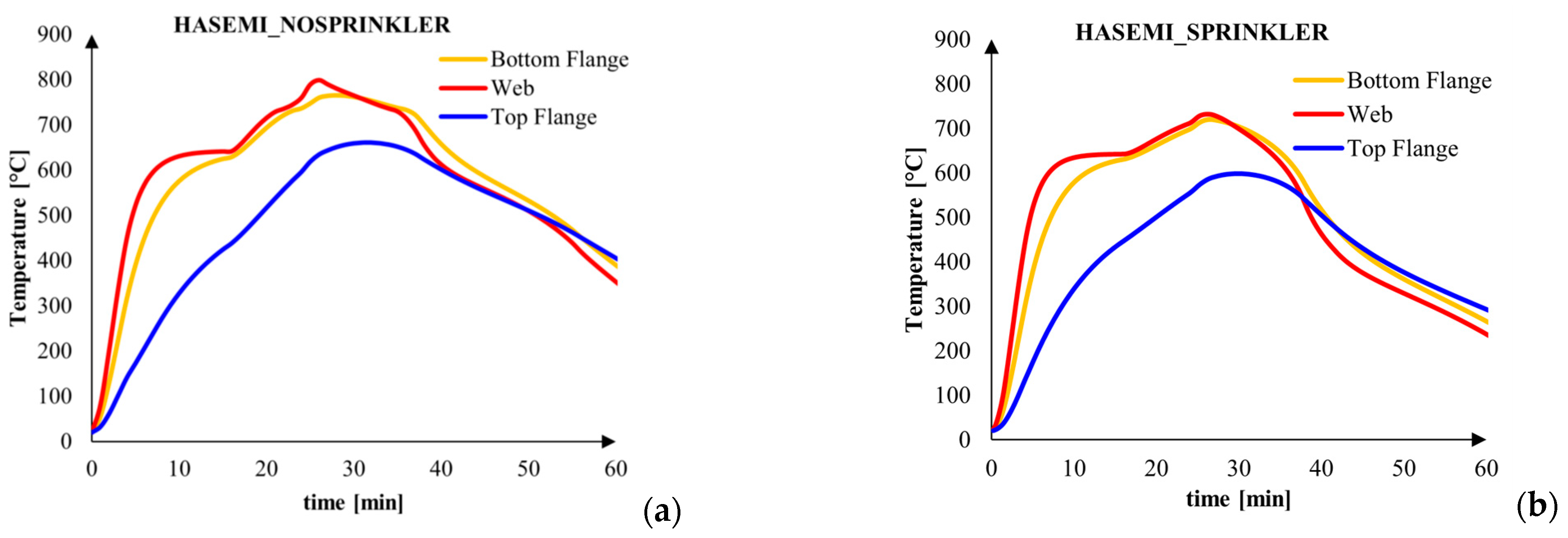
The temperature evolution inside the cross section of structural element is one of the most relevant aspects that influences the fire behaviour of the whole structure. Therefore, the thermal analysis of the element is one of the crucial steps. In the following, the thermal analyses of the composite steel-concrete beam described in the Section 2 was conducted, under the fire inputs described before. The Figure 14 shows the steel temperature in the bottom flange, web and top flange, under the Hasemi model. In particular, it can be observed that the sprinkler system reduced the temperature and the peak from about 800 °C, to about 750 °C. As shown in both Figure 14a and Figure 14b, the web heated up more than the bottom flange, since its Am/V is greater than the bottom flange one.
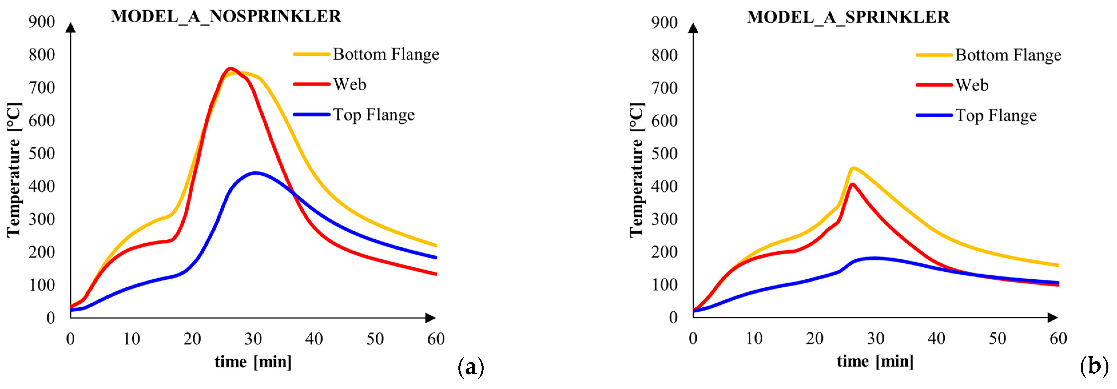
Moving on the Figure 15, which represents the steel temperature under the Model_A, the same consideration of the previous case can be done; however, in the case of sprinkler activation (the Figure 15b), the section factor effect became less evident and the bottom flange was more heated because the input AST is greater.
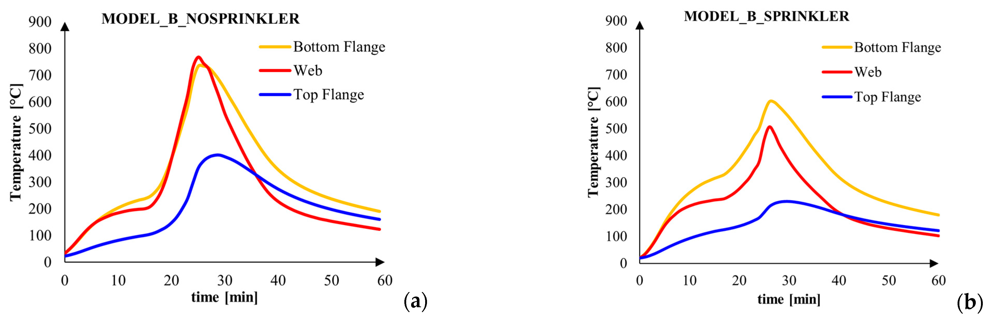
All the same considerations about the Model_A can be conducted also on the Model_B, observing the Figure 16.
In all the cases, comparing the web and the top flange temperature, the effect of the slower cooling of the top flange emerges; indeed, this section part is the slowest to heat up since its smallest Am/V and the concrete slab subtracts heat by conduction from the steel flange. In addition, in the cooling phase, the top flange becomes cold more slowly because the concrete, with its high thermal inertia, delays the steel cooling.
4.3. Comparison between Fire Models
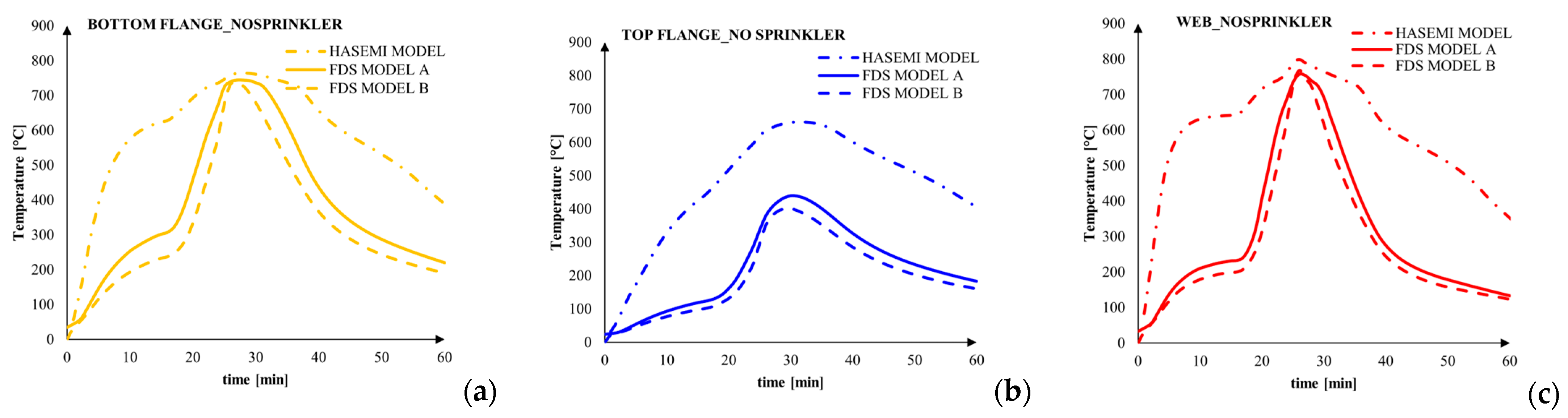
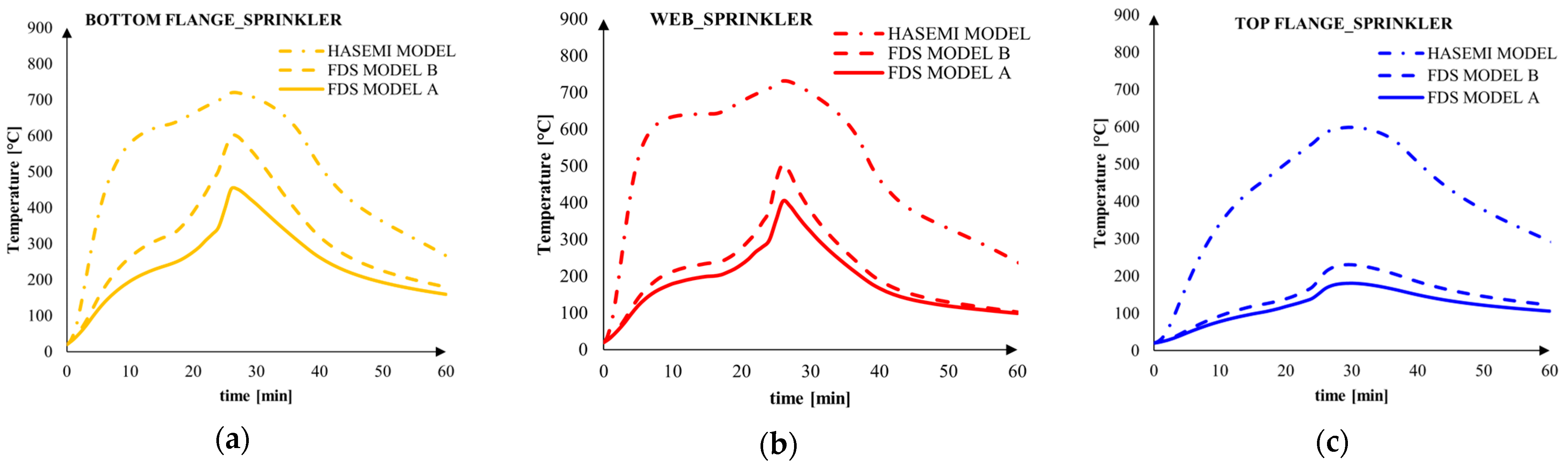
The steel temperature evolutions were also compared for each element of the cross section (bottom flange, web ad bottom flange) as function of the localized fire model. As seen in the Figure 17, for all three analysed elements, the comparison leads to the same results, i.e., more accurate is the model, lower are the temperature and the heating rate of the steel profile.
Very similar results were also achieved by other previous researchers. In particular, Yan et al. obtained the same result analysing an open car park [7] and its steel beam [24] under a localised fire. Indeed, comparing the results of the simple localised fire models and the FDS analysis, the Hasemi model results overconservative in terms of temperatures evolution in the structural elements at the ceiling level during the fire, because in this model, the flames touching ceiling during the whole fire duration is assumed.
In the case of absence of sprinkler, the Hasemi temperature overestimation was more evident in the heating and cooling phase, but the temperature peak is very similar in all the three models for bottom flange and web. This result was not confirmed for the top flange, where the different heating condition leaded to different temperature between Hasemi and FDS. In all the cases, the model_A returned temperature slightly higher than the model_B. For the analyses with sprinkler (see the Figure 18), the HASEMI model overestimates the temperature during all the thermal transient, while Model_A and Model_B returned very similar temperature, even if in this case the higher one is related to Model_B. This result is related to the different AST registered by FDS.
4.4. Sprinkler Effect on Steel Temperature
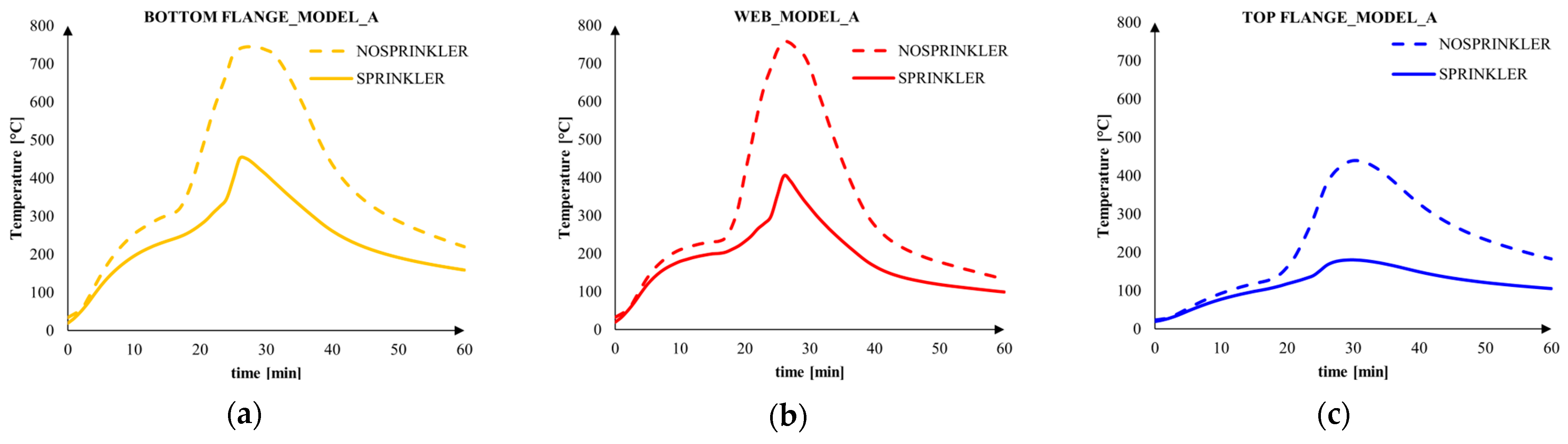
Focusing on Model_A, i.e., the 3D flame models in FDS., the comparison between steel temperature with and without sprinkler system was conducted (see Figure 19). This comparison was conducted also by Poon, obtaining similar results. In particular, the performance of sprinkler protection offers the ability to control the fire before it becomes fully developed, a measure which passive protection is not able to provide [25].
Reducing the potential development of a fire offers also other advantages such as reducing potential damage and allowing a much easier access for fire rescue and intervention teams. In all the cases the steel temperature benefitted from the sprinkler.
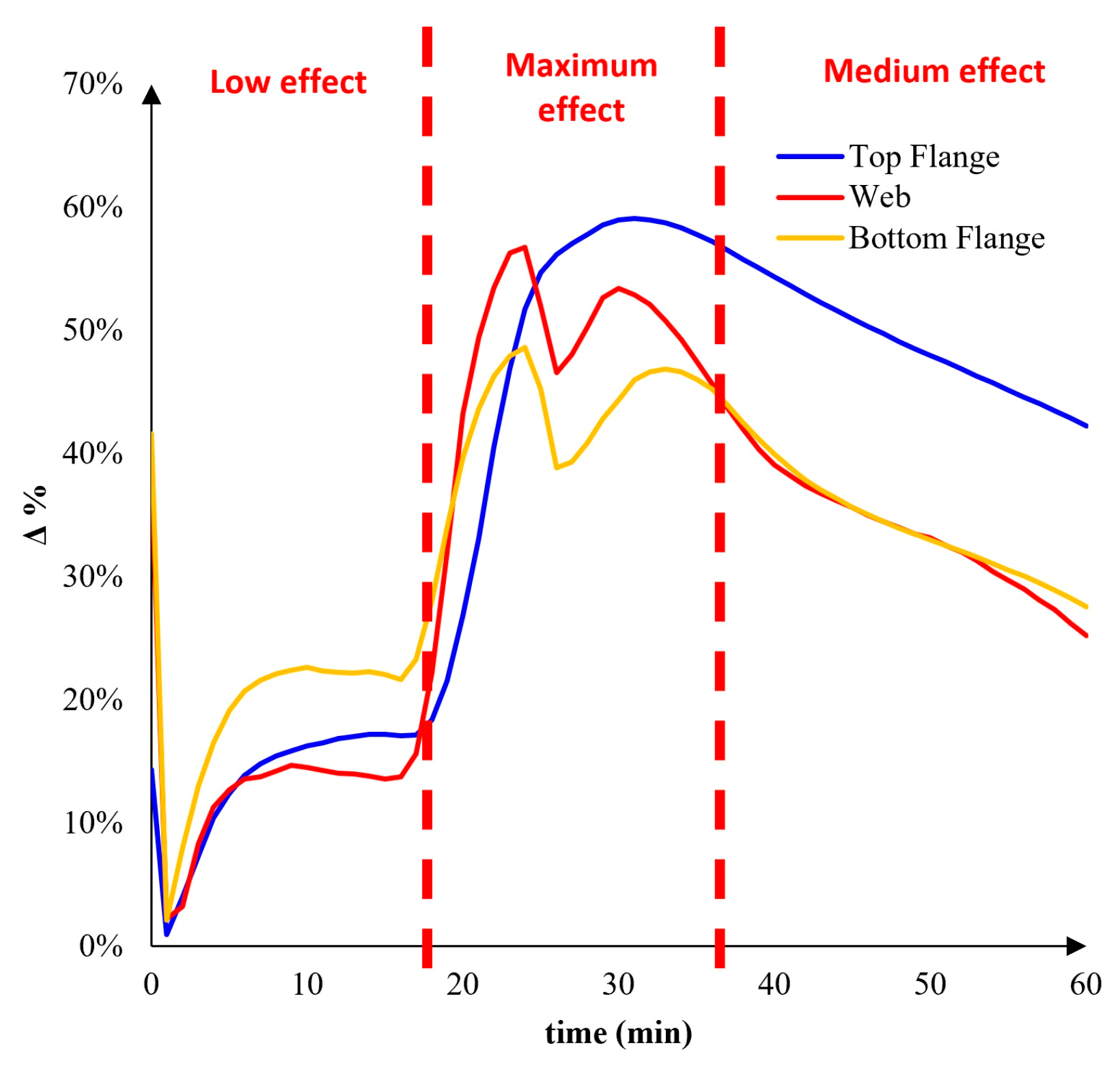
To have a better estimation of the sprinkler effect during the thermal transient, the value of Δ% was considered:
where θSPRINKLER is the temperature with sprinkler effect, while θNO_SPRINKLER is the steel temperature without sprinkler effect (see Figure 20).
In particular, the Figure 20 shows that:
- -
- between 0 and about 20 min the effect of the sprinkler is low, since Δ% is less than 30%;
- -
- the maximum effect is reached between about 20 and 40 min, reaching also Δ% about 60% for the top flange;
- -
- between 40 and 60 min the sprinkler effect decreased especially for web and bottom flange.
5. Conclusions
The main objective of the paper is to study the effect of the different localised fire models on the flame evolution, gas temperature and steel temperature, with reference to a localized fire due to a car burning in an open car park.
Assessing the simulation results in terms of fire effects, the following conclusions can be pointed out:
- in all the cases the maximum adiabatic surface temperature was recorded beside the lower flange; this is due to the greater proximity to the fire source;
- the presence of sprinkler reduced the adiabatic surface temperatures;
- the adiabatic surface temperature recorded beside web and top flange are very similar, demonstrating a comparable thermal input flux;
- the model with 3D fire source returned higher temperatures than flat flame modelling in the case of absence of sprinkler.
All these effects were considered also with reference to the steel temperatures of a typological steel-concrete beam, and the main evidences can be summarized as following:
- generally, the web is more heated than the bottom flange, since its section factor Am/V is greater;
- the top flange is the coolest one, since it has the smallest Am/V and the concrete slab subtracts heat by conduction;
- comparing the web and the top flange temperature, the effect of the slower cooling of the top flange emerges. Indeed, the top flange becomes cold more slowly because the concrete, with its high thermal inertia, delays the cooling;
- more accurate is the localised fire model, lower are the temperature and the heating of the steel profile;
- the maximum effect of the sprinkler is reached between about 20 and 40 min.
The main results of this paper show the importance of using the most accurate model to simulate the natural fire, if a performance-based approach is used. Indeed, one relevant aspect is to obtain a correct estimation of both the fire parameters (e.g., flame and temperature evolution) and the temperature in the structural elements. Both aspects can affect the fire safety objectives: protection of life, protection of property/structure and continuity of operation.
In future, the modelling of more fire scenarios, e.g., involving more cars, will be carried out and the wind effect, that could be relevant in the case of ventilated open car park will be also considered in the CFD analyses.
Author Contributions
Conceptualization, D.d.S., S.S., G.D.R.; methodology, D.d.S. and G.D.R.; software, D.d.S., S.S., G.D.R., G.C.; validation, D.d.S., G.D.R. and G.C.; formal analysis, G.D.R. and G.C..; investigation, G.D.R. and G.C.; resources, D.d.S., S.S. and E.N.; data curation, D.d.S., G.D.R. and E.N.; writing—original draft preparation, D.d.S. and G.D.R.; writing—review and editing, D.d.S. and G.D.R.; visualization, D.d.S., S.S. and E.N.; supervision, D.d.S., S.S. and E.N.; project administration, D.d.S., S.S. and E.N.; funding acquisition, D.d.S., S.S. and E.N. All authors have read and agreed to the published version of the manuscript.
Funding
This research received no external funding.
Institutional Review Board Statement
Not applicable.
Informed Consent Statement
Not applicable.
Data Availability Statement
Not applicable.
Conflicts of Interest
The authors declare no conflict of interest.
References
- EN 1991-1-2; Eurocode 1: Actions on Structures—Part 1–2: General Actions—Actions on Structures Exposed to Fire. European Committee for Standardization: Brussels, Belgium, 2002.
- ISO 834-1; Fire-Resistance Tests—Elements of Building Construction—Part 1: General Requirements. 1st ed. International Organization for Standardization: London, UK, 15 September 1999.
- Heskestad, G. Engineering relations for fire plumes. Fire Saf. J. 1984, 7, 25–32. [Google Scholar] [CrossRef]
- Pchelintsev, A.; Hasemi, Y.; Wakarnatsu, T.; Yokobayashi, Y. Experimental and numerical study on the behavior of a steel beam under ceiling exposed to a localized fire. In Fire Safety Science, In Proceedings of the 5th International Symposoum; IAFSS: Melbourne, Australia, 1997. [Google Scholar]
- Tondini, N.; Thauvoye, C.; Hanus, F.; Vassart, O. Development of an analytical model to predict the radiative heat flux to a vertical element due to a localised fire. Fire Saf. J. 2019, 105, 227–243. [Google Scholar] [CrossRef]
- de Silva, D.; Andreini, M.; Bilotta, A.; De Rosa, G.; La Mendola, S.; Nigro, E.; Rios, O.R. Structural safety assessment of concrete tunnel lining subjected to fire. Fire Saf. J. 2022, 134, 103697. [Google Scholar] [CrossRef]
- Yan, X.; Charlier, M.; Gernay, T. Thermal response on steel framing members in open car park fires. Front. Struct. Civ. Eng. 2022, 16, 1071–1088. [Google Scholar] [CrossRef]
- Nigro, E.; Cefarelli, G.; Ferraro, A.; Manfredi, G.; Cosenza, E. Fire Safety Engineering for open and closed car parks: C.A.S.E. Project for L’Aquila. In Applied Mechanics and Materials; Trans Tech Publications Ltd.: Wollerau, Switzerland, 2011; Volume 82, pp. 746–751. [Google Scholar]
- Wang, X.; Fleischmann, C.; Spearpoint, M. Assessing the influence of fuel geometrical shape on fire dynamics simulator (FDS) predictions for a large-scale heavy goods vehicle tunnel fire experiment. Case Stud. Fire Saf. 2016, 5, 34–41. [Google Scholar] [CrossRef] [Green Version]
- Ghodrat, M.; Shakeriaski, F.; Nelson, D.; Simeoni, A. Existing Improvements in Simulation of Fire–Wind Interaction and Its Effects on Structures. Fire 2021, 4, 27. [Google Scholar] [CrossRef]
- Khan, A.A.; Nan, Z.; Jiang, L.; Gupta, V.; Chen, S.; Khan, M.A.; Hidalgo, J.; Usmani, A. Model characterisation of localised burning impact from localised fire tests to travelling fire scenarios. J. Build. Eng. 2022, 54, 104601. [Google Scholar] [CrossRef]
- Hidalgo, J.P.; Goode, T.; Gupta, V.; Cowlard, A.; Abecassis-Empis, C.; Maclean, J.; Bartlett, A.I.; Maluk, C.; Montalvá, J.M.; Osorio, A.F.; et al. The Malveira fire test: Full-scale demonstration of fire modes in open-plan compartments. Fire Saf. J. 2019, 108, 102827. [Google Scholar] [CrossRef]
- Nadjai, A.; Naveed, A.; Charlier, M.; Vassart, O.; Welch, S.; Glorieux, A.; Sjostrom, J. Large scale fire test: The development of a travelling fire in open ventilation conditions and its influence on the surrounding steel structure. Fire Saf. J. 2022, 130, 103575. [Google Scholar] [CrossRef]
- Franssen, J.M.; Kodur, V.; Zaharia, R. Designing Steel Structures for Fire Safety; CRC Press: Boca Raton, FL, USA, 2009. [Google Scholar] [CrossRef]
- EN 1994-1-1; Eurocode 4: Design of Composite Steel and Concrete Structures—Part 1-1: General Rules and Rules for Buildings. European Committee for Standardization: Brussels, Belgium, 1994.
- EN 1994-1-2; Eurocode 4—Design of Composite Steel and Concrete Structures—Part 1-2: General Rules—Structural Fire Design. European Committee for Standardization: Brussels, Belgium, 1994.
- Thanaraj, D.P.; Kiran, T.; Kanagaraj, B.; Nammalvar, A.; Andrushia, A.D.; Gurupatham, B.G.A.; Roy, K. Influence of Heating–Cooling Regime on the Engineering Properties of Structural Concrete Subjected to Elevated Temperature. Buildings 2023, 13, 295. [Google Scholar] [CrossRef]
- Othuman Mydin, M.A. Evaluation of the Mechanical Properties of Lightweight Foamed Concrete at Varying Elevated Temperatures. Fire 2023, 6, 53. [Google Scholar] [CrossRef]
- Zhao, B.; Roosefid, M. Guide for Verification of the Fire Behavior of Largely Ventilated Car Parks with Metal Superstructure CTICM Document (SRI-11/110h-MR-BZ/NB); CTICM: Saint-Aubin, France, 2014. (In French) [Google Scholar]
- D.M. 3 agosto 2015 “Approvazione di Norme Tecniche di Prevenzione Incendi, ai Sensi Dell’articolo 15 del Decreto Legislativo 8 Marzo 2006, n. 139”, GU n. 192 del 20/8/2015–S.O. n. 51. Available online: http://www.gazzettaufficiale.it/eli/id/2015/08/20/15A06189/sg (accessed on 1 January 2023). (In Italian).
- Franssen, J.M. SAFIR: A thermal/structural program for modeling structures under fire. Eng. J. 2005, 42, 143–158. [Google Scholar]
- McGrattan, K.; Hostikka, S.; McDermott, R.; Floyd, J.; Weinschenk, C.; Overholt, K. Fire Dynamics Simulator, User’s Guide; NIST Special Publication: Gaithersburg, MD, USA, 2013. [Google Scholar]
- Wickström, U.; Duthinh, D.; McGrattan, K. Adiabatic Surface Temperature for Calculating Heat Transfer to Fire Exposed Structures. In Proceedings of the Eleventh International Interflam Conference, Interscience Communications, London, UK, 3–5 September 2007; Available online: https://tsapps.nist.gov/publication/get_pdf.cfm?pub_id=900083 (accessed on 30 January 2023).
- Yan, X.; Gernay, T. Numerical modeling of localized fire exposures on structures using FDS-FEM and simple models. Eng. Struct. 2021, 246, 112997. [Google Scholar] [CrossRef]
- Poon, L. Assessing the reliance of sprinklers for active protection of structures. Procedia Eng. 2013, 62, 618–628. [Google Scholar] [CrossRef] [Green Version]
Figure 1.
3D analysed sub-structure model.

Figure 2.
Composite beam dimensions.

Figure 3.
Fire position: (a) 3D localization with the analysed beam (in red); (b) plan location.

Figure 4.
HRR curve of one class 3 car.

Figure 5.
Heskestad model.

Figure 6.
Hasemi model.

Figure 7.
3D flame car FDS Simulation.

Figure 8.
Flat flame car FDS Simulation.

Figure 9.
Surface exposed to the FDS natural fire curves and steel section factors.

Figure 10.
Adiabatic surface temperatures: (a) model_A_nosprinkler; (b) model_A_sprinkler.

Figure 11.
Adiabatic surface temperatures: (a) model_B_nosprinkler; (b) model_B_sprinkler.

Figure 12.
flame evolution: (a) MODEL_A_nosprinkler; (b) MODEL_B_ nosprinkler.

Figure 13.
Temperatures evolution: (a) MODEL_A_nosprinkler; (b) MODEL_B_ nosprinkler.

Figure 14.
Steel temperatures evolution: (a) Hasemi_nosprinkler; (b) Hasemi_sprinkler.

Figure 15.
Steel temperatures evolution: (a) MODEL_A_nosprinkler; (b) MODEL_A_ sprinkler.

Figure 16.
Temperatures evolution: (a) MODEL_A_nosprinkler; (b) MODEL_B_ nosprinkler.

Figure 17.
Steel temperature by varying the fire models, without sprinkler system in: (a) bottom flange; (b) web, (c) top flange.
Figure 17.
Steel temperature by varying the fire models, without sprinkler system in: (a) bottom flange; (b) web, (c) top flange.

Figure 18.
Steel temperature by varying the fire models, with sprinkler: (a) bottom flange; (b) web, (c) top flange.
Figure 18.
Steel temperature by varying the fire models, with sprinkler: (a) bottom flange; (b) web, (c) top flange.

Figure 19.
Steel temperature by varying the fire models, with sprinkler system in: (a) bottom flange; (b) web, (c) top flange.
Figure 19.
Steel temperature by varying the fire models, with sprinkler system in: (a) bottom flange; (b) web, (c) top flange.

Figure 20.
Estimation of the sprinkler effect (Δ%).


Table 1.
Main aspects of performed analyses.
| Analysis | Localised Fire Model | Active System | Fire Source | Name |
|---|---|---|---|---|
| 1 | Hasemi | no | - | Hasemi_nosprinkler |
| 2 | Hasemi | yes | - | Hasemi_sprinkler |
| 3 | FDS | no | 3D | model_A_nosprinkler |
| 4 | FDS | yes | 3D | model_A_sprinkler |
| 5 | FDS | no | flat | model_B_nosprinkler |
| 6 | FDS | yes | flat | model_B_sprinkler |
Disclaimer/Publisher’s Note: The statements, opinions and data contained in all publications are solely those of the individual author(s) and contributor(s) and not of MDPI and/or the editor(s). MDPI and/or the editor(s) disclaim responsibility for any injury to people or property resulting from any ideas, methods, instructions or products referred to in the content. |
© 2023 by the authors. Licensee MDPI, Basel, Switzerland. This article is an open access article distributed under the terms and conditions of the Creative Commons Attribution (CC BY) license (https://creativecommons.org/licenses/by/4.0/).
Share and Cite
MDPI and ACS Style
de Silva, D.; Sassi, S.; De Rosa, G.; Corbella, G.; Nigro, E. Effect of the Fire Modelling on the Structural Temperature Evolution Using Advanced Calculation Models. Fire 2023, 6, 91. https://doi.org/10.3390/fire6030091
AMA Style
de Silva D, Sassi S, De Rosa G, Corbella G, Nigro E. Effect of the Fire Modelling on the Structural Temperature Evolution Using Advanced Calculation Models. Fire. 2023; 6(3):91. https://doi.org/10.3390/fire6030091
Chicago/Turabian Stylede Silva, Donatella, Samuele Sassi, Gabriella De Rosa, Giorgio Corbella, and Emidio Nigro. 2023. "Effect of the Fire Modelling on the Structural Temperature Evolution Using Advanced Calculation Models" Fire 6, no. 3: 91. https://doi.org/10.3390/fire6030091