
Mechanical Efficiency and Quality Control Preliminary Analysis of Incompletely Bonded Wood-Based Sandwich Panels

1
Department of Forestry and Environmental Engineering and Management, MONTES (School of Forest Engineering and Natural Resources), Universidad Politécnica de Madrid, 28040 Madrid, Spain
2
Continuum Mechanics and Structural Analysis Department, Universidad Carlos III de Madrid, 28911 Madrid, Spain
3
AITIM—Technical Research Association for the Wood Industries, 28013 Madrid, Spain
4
Institute of Forest Science (ICIFOR-INIA, CSIC), 28040 Madrid, Spain
*
Author to whom correspondence should be addressed.
Forests 2023, 14(6), 1074; https://doi.org/10.3390/f14061074
Submission received: 7 March 2023
/
Revised: 17 May 2023
/
Accepted: 18 May 2023
/
Published: 23 May 2023
(This article belongs to the Special Issue Wood Quality and Mechanical Properties)
Abstract
:Wood-based sandwich panels are building products composed of two skins attached to a lightweight continuous core in which at least one skin is made of wood-based products, contributing to the use of renewable forest goods. Since the connection between the skins and the core is often provided by adhesive bonding, its characteristics affect the mechanical behavior of the sandwich and, therefore, must be thoroughly assessed. Full adhesion is often considered the standard situation, although some batches of the commercial product show incompletely glued surfaces, and scarce data is available with regard to their bonding performance. For this reason, analyses were performed using tensile tests with a load perpendicular to the skins and specific shear tests with a load parallel to the longitudinal direction of the panel. The test samples were obtained from wood-based sandwich panels with extruded polystyrene cores and different skin materials. The tensile tests proved to be suitable only for panels with adequate skin material cohesion, their functionality improving as a control method when the glued surface percentage assessment is used together with the tensile strength. The results of the shear tests provided non-linear models relating the effect of the glued surface to the mechanical properties, revealing that the mechanical efficiency of the incompletely bonded specimens is better than that which might be expected if the core only worked in proportion to the glued surface, due to the help of the adjoining non-glued core material.
1. Introduction
Wood-based sandwich panels are multifunctional building products frequently used in Europe for roof and wall sheathing as secondary or tertiary structural elements. They are also being used as principal load-bearing elements, known as SIP (Structural Insulated Panels), particularly in North America and increasingly in Europe. These elements have two skins, of which at least one is made of wood or wood-based products [1]. The skins are bonded, generally using glue (except in some polyurethane cores of in situ manufactured panels), to a lightweight, continuous, and to some extent, rigid core. This core is frequently a closed-cell plastic foam, although natural insulation materials, such as expanded cork boards or wood fiber compact boards, are becoming more common.
Wood-based sandwich panels have a high stiffness-to-weight ratio together with other building characteristics of interest, such as thermal and acoustic insulation. Their use is growing due, on the one hand, to increased social interest in energy efficiency in buildings (sandwich panels provide a thermal envelope with better continuity than other building systems), and on the other, to their favorable environmental characteristics, especially in the case of those elements fully manufactured using natural and renewable materials.
Since the shear connection between the skins and the core is usually provided by adhesive bonding, the performance of this bonding is very important for the mechanical behavior of the product and, therefore, must be properly controlled and assessed. Most of the available research into the adhesive bonding of sandwich panels is related to metal and composite skin panels for aeronautic and building uses, e.g., [2,3,4], and although wood-based sandwich panels are an increasingly important research field [5,6], there is little specific information on their bonding performance.
Interest in the effect of delaminations or bonding defects in aeronautical uses dates back to the end of the 1940s and the beginning of the 1950s, with research into aluminium-faced sandwiches involving the use of non-destructive methods and localized methods such as button tension testing [7]; along with the analysis of the effect of non-glued areas on aluminium honeycomb panels using bending and small scale shear tests [8], the latter highlighting a reduction in mechanical properties in specimens with non-glued areas. Triantafilou and Gibson [4] assessed bending failures in high-performance aluminium and polyurethane panels with previously created bonding defects, finding that the bonding failures appeared only in sandwich elements with relatively large unbonded areas. Current analysis of debonding focuses, in particular, on safety issues caused by delaminations [9], with research into aspects such as the influence of the production process and the use of fracture mechanics test results as a basis for modeling tools.
Several references exist regarding sandwich panel bonding quality assessment for metal-faced sandwiches [10,11] and wood-based sandwiches [1,12,13]. These include tests such as the tensile test with loading perpendicular to the skins and short-span bending tests, both using small specimens. Furthermore, some research references include the use of shear tests on small or medium-sized sandwich panel specimens, mainly dealing with fully glued panels [5,14,15] or with climatic aging effect evaluation [6], the assessment of incomplete bonded surfaces, as mentioned, not being focused on wood-based sandwich panels [4]. Many studies generally assess or model debonding either as localized damage [9,16,17] or within the field of fracture mechanics, e.g., [18,19,20]. Others focus on the improvement of mechanical behavior through additional adhesive application [21] or through bonded interconnection of sandwich panels [22]. On the other hand, regarding the amount of adhesive used, most of the research carried out is aimed at reducing the use of glue in honeycomb-cored sandwich panels [23] or at analyzing the amount of glue needed in fibrous cores [24].
With regard to the bonding of the sandwich panels used in construction, it is commonly assumed that skin adhesion to the core is complete [25], except in sandwich panels with non-fully-continuous cores such as honeycomb [26]. However, this premise is not always fulfilled, especially in secondary structural wood sandwich panels for building purposes, as some authors [27,28] have reported the presence of incompletely bonded faces in batches of commercial products.
Although incomplete gluing is considered undesirable, especially if it leads to a lack of homogeneity in the mechanical response, scarce research has been directed toward understanding its main characteristics and implications and thus determining the effects on mechanical properties and quality. The analysis of incompletely bonded sandwich panels can help to establish minimum thresholds for bonded surfaces in accordance with the end use of the product. In addition, these analyses provide an important opportunity to assess the reliability of quality control test methods for the detection of bonding defects on small and medium-sized bonded surfaces.
Finally, it is also necessary to review the results of the bonding control test methods for wood-based sandwich panels with regards to skin cohesion and surface soundness since the expected results for a metal-faced sandwich, which point to a failure in fully-bonded elements appearing in the core and not the skins [25], is not likely to be the case in some types of wood-based panels, where the face materials can present less internal strength or surface soundness than the core material.
For the above reasons, an experimental study was undertaken in this research to gain greater insight into the characteristics and effects of cohesion of the face materials and of incompletely bonded skins. Two different test methods for quality control and research were used on batches of common types of wood-based sandwich panels with extruded polystyrene cores, in which incompletely bonded faces were previously visually detected as a result of other mechanical tests not included in the present research.
The panels tested correspond to commonly manufactured wood-based sandwich panels in the Spanish market. The research performed is a preliminary analysis using these types of panels.
2. Materials and Methods
2.1. Panels Sampled and Tests Performed
Four types of wood-based sandwich panels obtained from two commercial batches were used for the analysis. Tensile tests with load perpendicular to the skins, as well as shear tests with load parallel to the longitudinal direction of the panel, were performed. The details of the panels assessed and tests performed are summarized in Table 1.
The panels sampled, with a width of 550–600 mm and length of 2400 mm, had skins glued to the core using polyurethane (PUR) adhesives and did not have a fully glued surface, as mentioned above. This condition had been detected in previous small-scale tests not included in this research. The upper skin was of 10–19 mm thick particleboard, the core was 40 to 50 mm thick XPS foam (30–34 kg/m3), and the lower skin was 10–19 mm thick and composed of three materials with different expected internal cohesion: spruce boards, gypsum-fiber boards, and cement-bonded wood wool boards.
The panel types were chosen as they were some of the most commonly used in Spain. They were additional non-tested panels of previous testing series. It was decided to use all the available elements, which were a series of 3 panels, except 4 panels of the type PB19-XPS40-SB19.
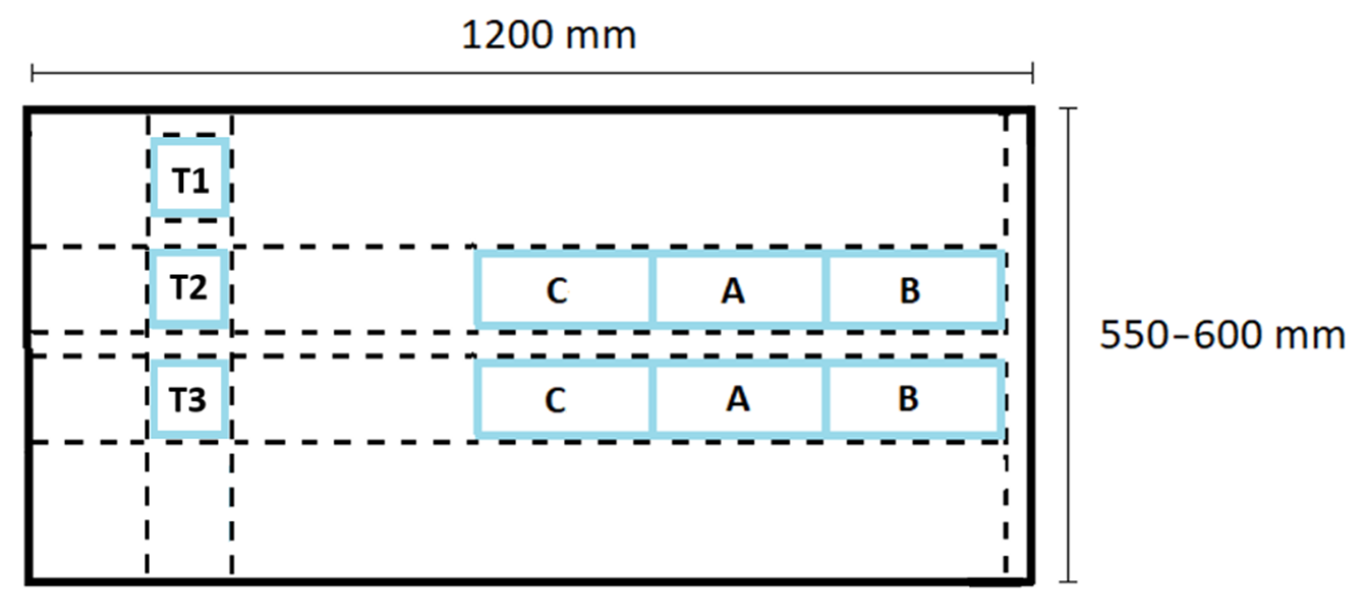
Figure 1 shows the general cutting plan for specimens in a sandwich panel. Tensile tests (specimens T1-T3), the most common method for quality control of bonding, were used in the first phase to assess the bonding and evaluate the cohesion of the skins. In the case of panels with the highest internal cohesion of the skin according to the tensile test results (which, as will be seen, were those with particleboard and spruce board faces), double specimen shear tests A, B, C (the latter only in one panel type) were used to assess the mechanical efficiency of the bonding.
2.2. Tensile Test with Load Perpendicular to the Skins
A transversal strip was obtained from each sampled sandwich panel, taken in a random position adjacent to the shear sampling area. From this strip, 3 specimens were cut.
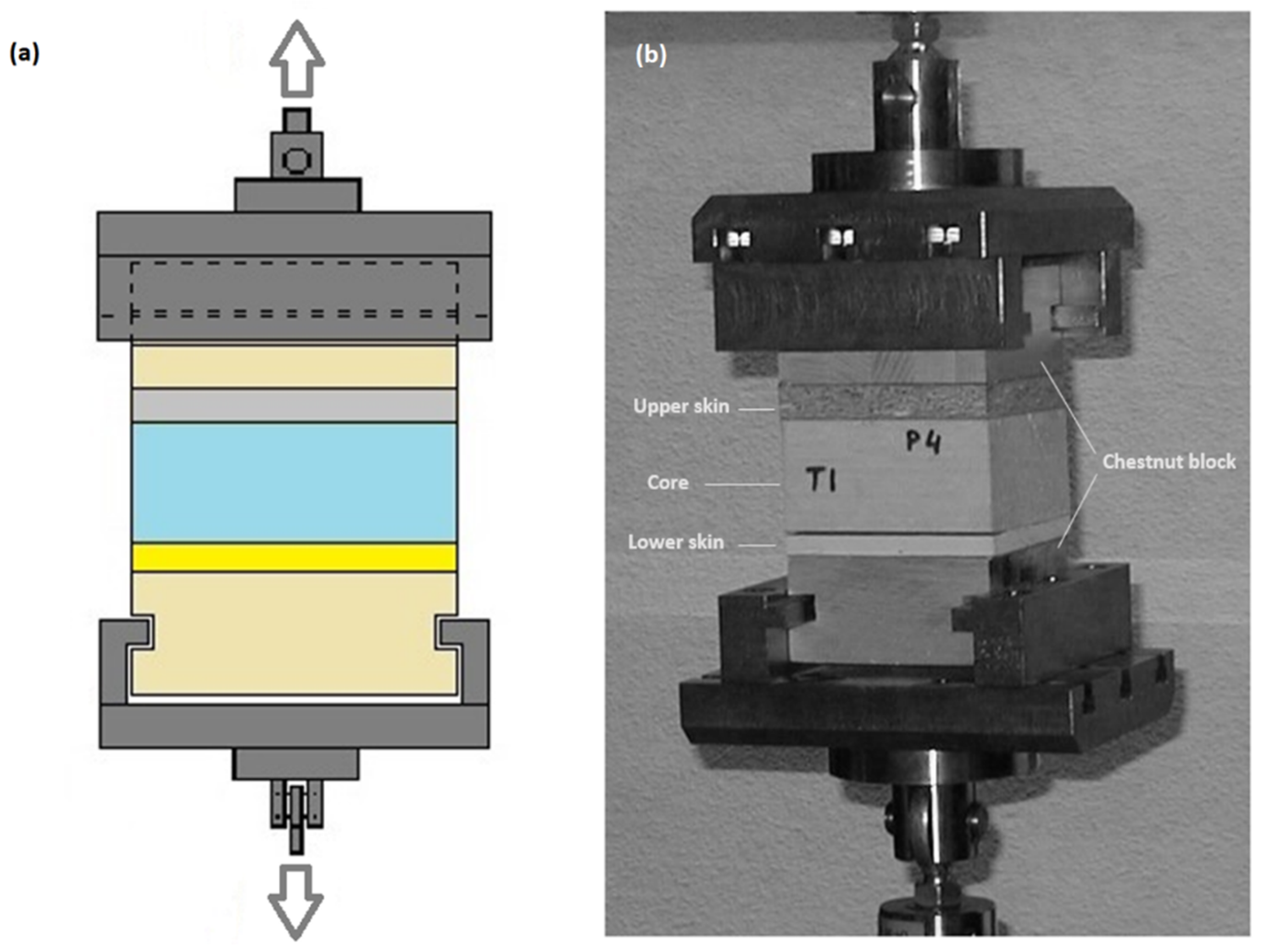
The equipment used was a universal test machine (INSTRON) and software of MICROTEST applying a constant displacement rate. A system of two wood blocks of sweet chestnut (Castanea sativa Mill.) was used for transmitting and distributing the load from the test machine fixture to each specimen. These blocks were glued to the skins of the sandwich specimens using polyvinyl acetate (PVA) adhesive and pressed until the adhesive cured. The sets comprising the specimens and the wooden blocks were then attached to a specific tensile test fixture through grooves purposely machined on the blocks, Figure 2.
The test sets were kept at a temperature between 20–28 °C and relative humidity of 40%–48% during the bonding, storage, and testing.
Once the preparation was complete, the test was performed according to the indications provided by the European guideline ETAG 16, part 1, annex C, section C3 [1]. The specimens and wooden block sets were tested in tension perpendicular to the skins with a constant displacement of between 1% and 3% relative deformation per minute in relation to the core thickness until the set failed.
The ultimate load, the failure description, and the glued surface percentage (GSP) in the failed skin (if failure due to the bonding was present) were recorded. No failures were observed in the bonding of the sweet chestnut blocks to the specimens.
With the information obtained, the tensile strength was calculated as follows:
Being:
- ft —Tensile strength perpendicular to the skins (N/mm2);
- Fu —Ultimate load recorded in the test (N);
- B —Square cross-section width (mm) of the specimen.
GSP is a key variable in the analysis and corresponds to the percentage of the adhered surface of the core on the skin, or of skin on the core, depending on the surface soundness of the materials tested. It was considered in those sandwich specimens that failed in the interface between the core and the face when assessing the failed bonded surface. See Section 2.3 for more details.
2.3. Shear Test with Load Parallel to the Longitudinal Direction of the Panel
For these tests, a universal test machine was used (IBERTEST PFIB 600–300 W). Adjacent specimens (A, B, C) were obtained, Figure 1, oriented parallel (lengthways) to the longitudinal direction of the panel, each with a width of 75–100 mm and length of 200 mm, including their complete thickness:
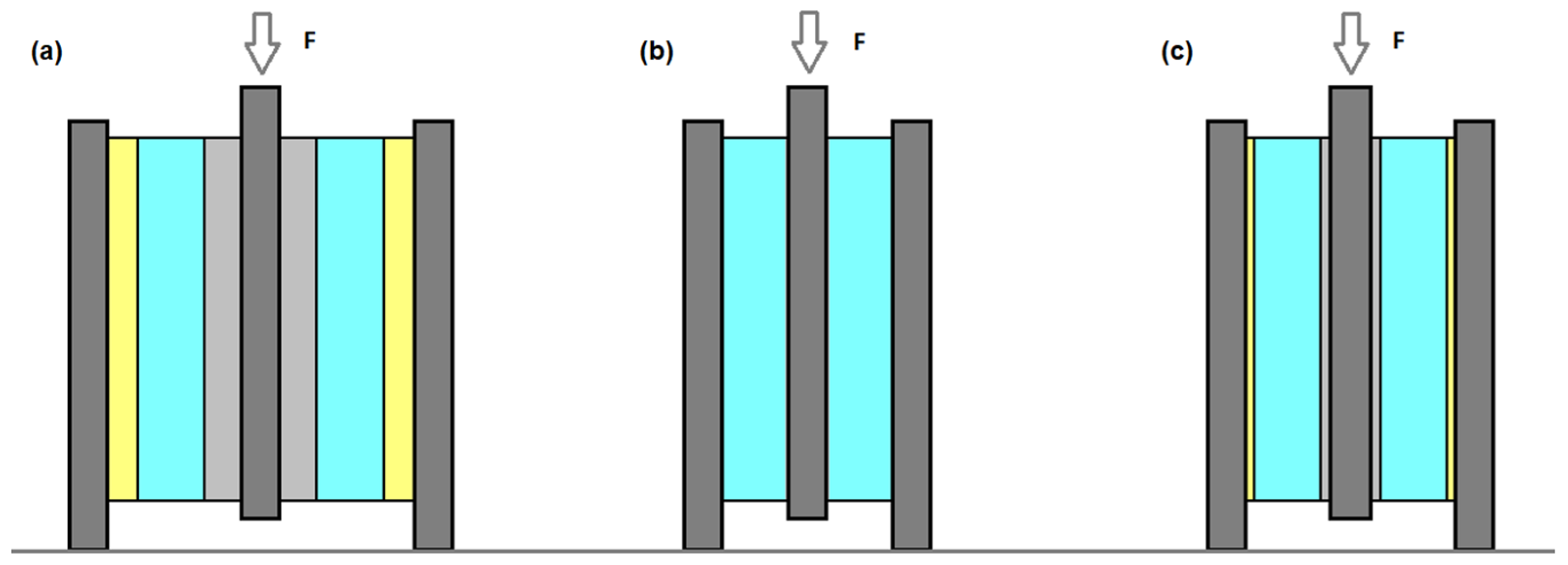
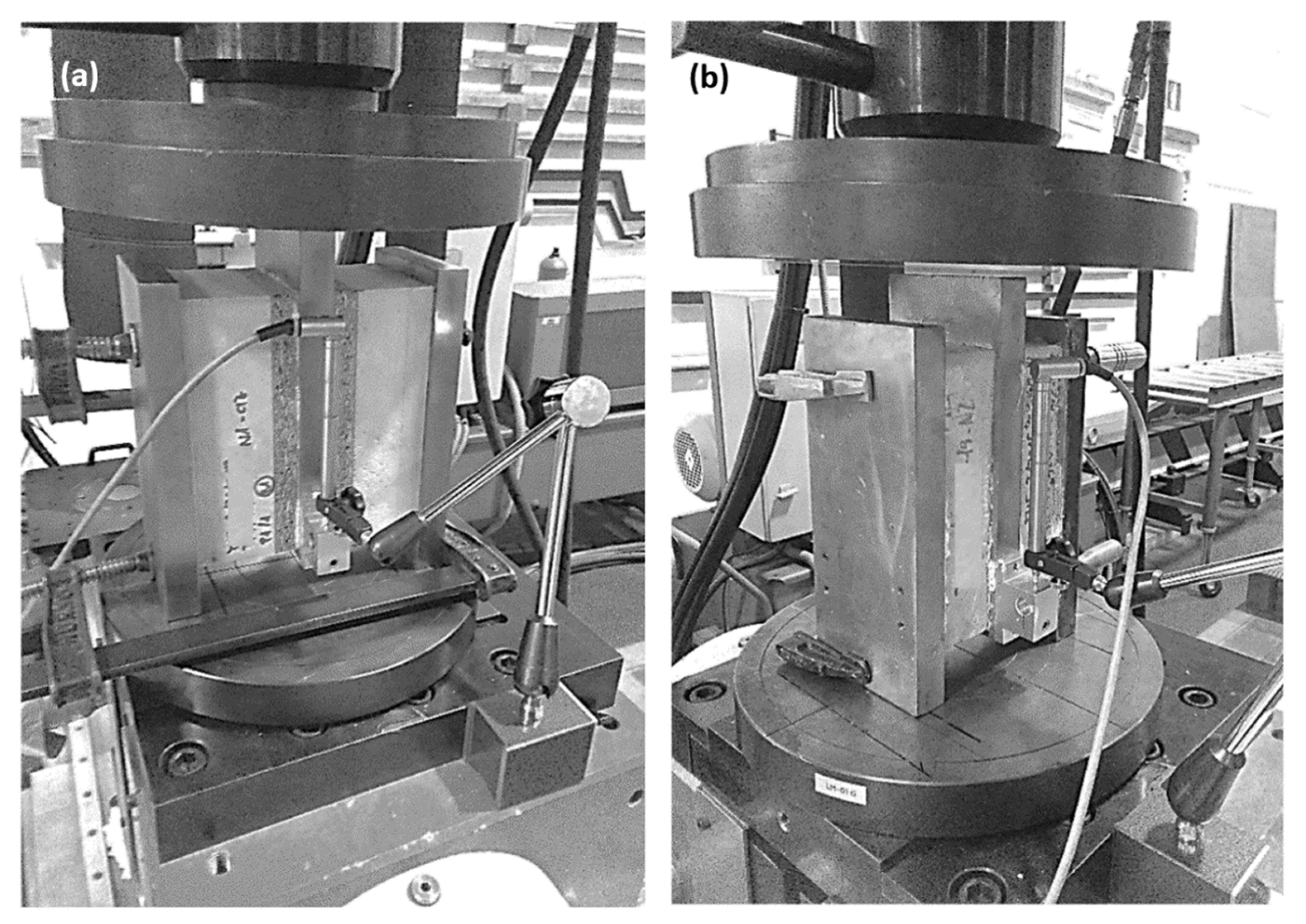
- Two of these specimens, “A” specimens, Figure 3a, were tested directly, and these had skins bonded to the core. Each pair were fully bonded to three steel plates using a PUR 1C (one-component) adhesive, forming a test set, Figure 4a. The glue was applied on the exterior surface of the skin and pressed until the adhesive cured;
- In another two specimens of each panel, “B” specimens, Figure 3b, the skins were eliminated while removing as little core as possible, reducing the thickness of the foam by around 4 mm. Both foam specimens were then also glued directly to three steel plates to form a test set, Figure 4b. The same PUR 1C adhesive and gluing procedure applied to the “A” specimens were used.
- Finally, an additional set of two specimens per panel, “C” specimens, Figure 3c, were tested in one of the panel types. These were analogous to the corresponding “A” elements but with the thickness of the faces reduced to 3 mm.
The “A”, “B”, and “C” specimens were tested according to Figure 3, using the proposed shear test based on EN 12090 standard [29]; see also Figure 4. Shear strength, transversal modulus of elasticity, and glued surface percentage (GSP) were recorded.
All specimen types were fully glued (100% glued area) directly to the metal plates. The aim of each type of test was as follows:
- The “A” specimens test assesses the shear performance of the sandwich set, including the performance of the foam core and the factory-produced adhesive bond of the skins to the core;
- The “B” specimens test assesses the shear mechanical performance of the core foam when fully glued, which is assumed to be the shear behavior for fully glued sandwich panels;
- The “C” specimens test is similar to that for the “A” specimens. It is performed in order to evaluate the importance of the thickness of the faces in the results, using only one panel type as a reference, as mentioned before.
The tests were performed by compression loading at a constant displacement rate of 2–3 mm/min. The set displacement was measured by using an extensometer placed on the central steel plate. Two clamps were positioned on the upper and lower part of the test set to avoid lateral displacement of the plates during the tests.
Deflection-load curves and ultimate load values were recorded. The deflection-load rate in the linear part of the graph was taken to calculate the transversal modulus of elasticity, Geff, of the “A” and “C” tests (effective G value for the sandwich panel) and G for the “B” tests (value for the foam). The ultimate loads were taken as the maximum load in the “A” and “C” tests and as the load corresponding to 10% displacement (related to the core thickness) for the “B” tests. They were then used to calculate the shear strengths, fv,eff (effective value for the sandwich), and fv (value for the foam), respectively.
The following general expressions were used for the analysis:
Being:
- G—Transversal modulus of elasticity (N/mm2)
- fv—Shear strength (N/mm2)
- tc—Core thickness (mm)
- bc—Specimen width (mm)
- lc—Specimen length (mm)
- k—Test deformation-load rate (mm/N)
- Fu—Test ultimate load (N)
The specimens with incompletely bonded surfaces generally had a characteristic pattern of longitudinal glue stripes, as the adhesive was applied in parallel lines, see Figure 5a.
Shear stresses in the tests are oriented in the same direction as those in a panel under bending in service, parallel to the longitudinal direction of the specimens, and also parallel to the longitudinal glued stripes.
In the “A” and “C” specimens, the two glued surfaces of the failed specimen were opened and visually assessed after testing.
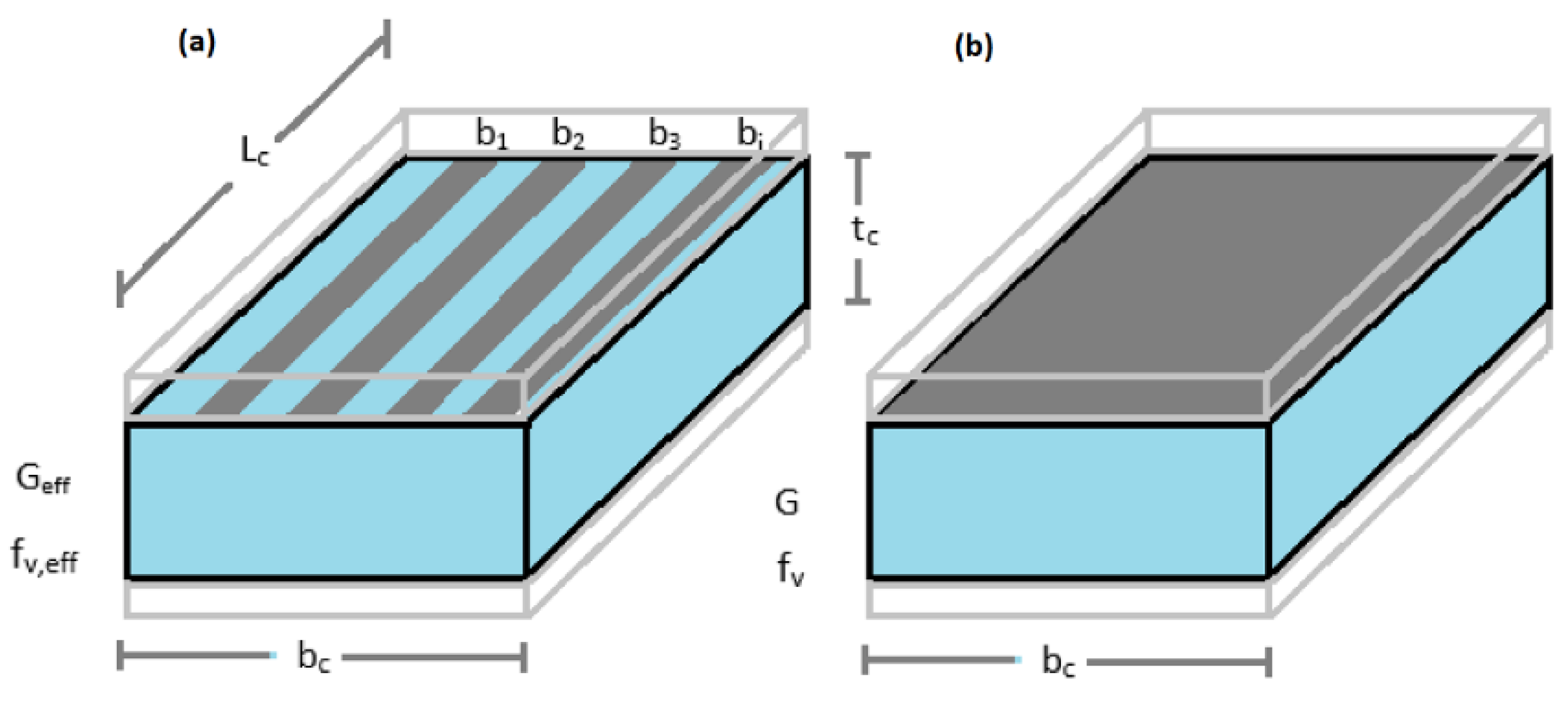
The glued surface percentage (GSP) was assessed as the percentage of surface on the skin in which the remaining foam was visibly attached by the adhesive since the skins were cohesive. If skin material was also present on the core, this was also considered. Minimum (worst surface), and average values (both surfaces), were recorded. The GSP value of a surface was calculated according to Equation (4), Figure 5.
2.4. Shear Efficiency Coefficients Definition
In order to assess the effect of the GSP on mechanical properties in greater depth, the ratio of the shear properties obtained in “A” and “B” specimen tests was related to the percentage of the glued surface observed in the “A” specimens, for each individual test, see Section 3.2.2. This was done to assess the possible correlation between these variables.
The following efficiency coefficients were previously defined for the comparison:
Being:
- ξgG—Efficiency coefficient due to the adhesive bonding performance for the transversal modulus of elasticity. Varying from 0, no efficiency, to 1, full efficiency, in which the sandwich specimen has the same shear properties as the core foam.
- ξgτ—Efficiency coefficient due to adhesive bonding performance for shear strength. This varies from 0 to 1, the latter of which corresponds to full efficiency.
- Geff—Effective transversal modulus of elasticity values obtained in the “A” specimen tests. This includes the shear performance of the core and the effect of the bonding.
- G—Transversal modulus of elasticity of the core obtained in the “B” specimen tests. This corresponds to the expected shear behavior of the fully glued sandwich panels.
- fv,eff—Effective shear strength values obtained in the “A” specimen tests. This corresponds to the shear performance of the core, including the effect of the bonding.
- fv—Shear strength values of the core obtained in the “B” specimen tests. This corresponds to the expected shear performance of the fully glued sandwich panels.
3. Results and Discussion
3.1. Tensile Test with Load Perpendicular to the Skins
3.1.1. General Analysis
Table 2 summarizes the tensile strength perpendicular to the skins and the average GSP results for the four types of wood-based sandwich panels tested, along with the variability of the results.
The tests showed three different failure modes:
Failure “i” is observed in the sandwich panels with solid wood and particleboard skins, PB19-XPS-SB19 and PB16-XPS-SB10. In these cases, incomplete bonding leads to a surface failure in the core material. The tensile strengths are among the highest obtained in the tests. In the context of this study, these panels will be referred to as “cohesive skin” sandwich panels, and their behavior corresponds to a situation in which the skin materials are at least as cohesive as the core material.
Failure “ii” appears in panels of type PB10-XPS-GF10 as a consequence of a local surface rupture in the gypsum-fiber board skin material in the incompletely glued areas. The average tensile strength, in this case, is significantly lower, at 66% of that observed in the “i” failure specimens with similar GSP, revealing that the lower surface soundness of the skin, in this case, leads to a lower tensile strength in the test.
Finally, failure “iii” occurs in the skins of cement-bonded wool-wood panels, in the interior and not on the glued surface, with a very low strength level (33% of the value obtained in the specimens with failure “i”). The GSP, in this case, has not been evaluated, although they are also very likely to present incomplete bonding, as was the case of the other types of panels belonging to batch 1. However, this could not be confirmed.
Based on the abovementioned observations, it is clear that the internal cohesion of the skins is important in the quality control of wood-based sandwich panels and that this characteristic differs from the expected behavior in sandwiches with metal faces, where failure is never associated with the skins. In more detail:
- The strength obtained in the tensile test is dependent on the material of the faces.
- The tensile test is not appropriate for quality control of bonding in a sandwich with faces of low surface soundness or internal cohesion, such as those using gypsum-fiber boards or cement-bonded wood-wool panels, due to the lower strength values obtained.
- The tensile test proved to be a suitable quality control method of bonding in panels with cohesive skins, such as wood or wood-based panels with high surface soundness and internal strength, as those manufactured with particleboard or solid wood. However, the tensile strength results present in general high variability (Table 2).
3.1.2. Regression Analysis
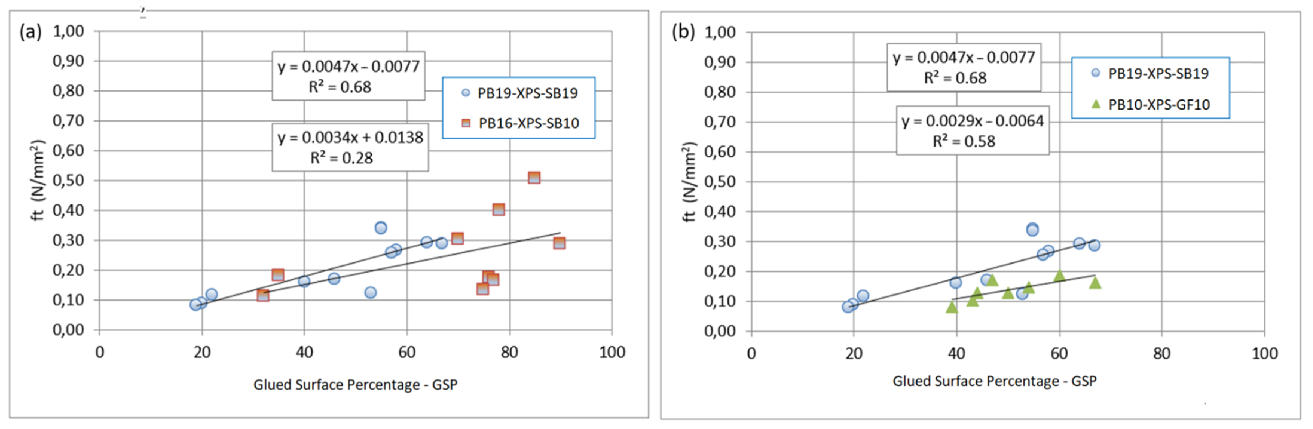
A detailed analysis was also performed for the individual values of the tests. Figure 7a shows the linear regression analysis of tensile strength vs. GSP for two similar panel types, with skins of particleboard and solid wood, belonging to two different commercial batches. It can be observed that in both cases, the tensile strength value increases with the increase in the GSP value, as expected. However, it can be seen that one of the batches fits a linear model with a moderate-high determination coefficient (R2 of 0.68), while the other presents a much lower correlation (R2 of 0.29) associated with higher scatter in the results.
The requirements of linearity, homoscedasticity, independence, and normality (Shapiro–Wilk test with p-value ≥ 0.05) of the variables of the linear regressions were assessed using Statgraphics software [30]. The p-values of the linear regressions were less than 0.05; therefore, there is a statistically significant relationship at the 95% confidence level. As an exception, the regression presented in Figure 7a with the lowest determination coefficient does not meet sufficient statistical requirements of normality and linearity. However, it has been considered for comparison purposes.
The higher variability seen in one of these batches can be considered an indicator of a more heterogeneous behavior in the adhesive response, which could be associated with the manufacturing process, showing that the use of diagrams relating GSP and tensile strength can be a useful, although indicative, tool for quality control, especially when used to assess the GSP and the strength variability.
Finally, in Figure 7b, the same comparison is performed between the best-fit particleboard and solid-wood skin sandwich panel depicted in Figure 7a and the type of sandwich with a gypsum-fiber board skin. It can be seen from the graph that in the case of the sandwich with gypsum-fiber board, the tensile strength shows a clear linear relationship with the GSP, although a lower strength can also be observed, associated with the local surface failure of the gypsum face. For this reason, the test appears to be of little interest for assessing the skin-core adhesive bonding, although its usefulness for assessing the GSP is patent.
3.2. Shear Tests with Load Parallel to the Longitudinal Direction of the Panel
3.2.1. General Analysis
As seen in the tensile tests, the assessment of the bonding characteristics requires the faces to present minimum integrity behavior when subjected to load, considering that the internal strength should be at least equal to or higher than that of the core material.
Bearing this in mind, only those panels with sufficient cohesion of their faces according to the tensile tests were assessed in the shear tests, in order to evaluate the incomplete bonding effect on the mechanical performance of the sandwich elements.
Table 3 summarizes the average test results for shear modulus of elasticity, shear strength, and GSP obtained in the analysis.
The table shows that the shear properties of the “A” specimens (bonding and core behavior) are lower than those of the “B” specimens (core behavior) in both panel types.
The results for the “C” specimens (similar elements to “A” but with reduced thickness of faces) showed behavior very similar to that observed in the “A” tests. This indicates that the reduction in properties observed in the ”A” specimens, when compared to the “B” specimens, is not strongly influenced by the effect of the mechanical behavior of the faces.
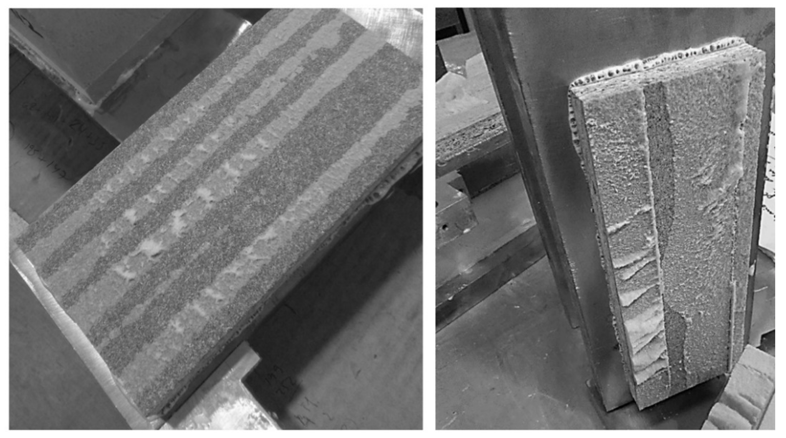
In both specimen types with skins bonded to the core (“A” and “C” specimens), when the failure occurred in the core-skin interface, a striped pattern associated with manufacturing using glue lines (Figure 8) was generally visible.
All failures in the “B” specimen tests (core adhered to metal plates) were located in the foam, while no failure of the bond to the metal plates was observed. As they were fully glued in the laboratory, their GSP was not visually assessed and was assumed to be 100%.
Bearing this in mind, the reduction in the shear mechanical properties observed in the “A” specimens compared to the shear behavior of the “B” specimen cores is assumed to be mainly due to the effect of the adhesive bonding performance as:
- the average GSP for the PB19-XPS-SB19 “A” specimens was low, around 40%, and these tests presented the lowest mechanical properties. All the specimens failed at the core-skin surface.
- the PB16-XPS-SB10 had incomplete but better GSP, at around 70%, showing decreased apparent shear properties, but in proportion, less than those observed in the PB19-XPS-SB19 tests. Only one test failed at the core-skin interface, while the other two tests failed in the foam.
CoV in C-type specimens was 10% lower for shear strength than the one found in A-type specimens. The lower thickness of the C skins compared to that of the A skins could justify this result, as the metal plates are closer to the core, and due to the higher rigidity of the steel compared to the wood-based products of the faces, this could result in a more uniform shear stress distribution in the C specimens.
The CoV for the average of GSP is in some cases reduced, as calculating the average of the values of both faces of the specimen that failed can diminish variability. When considering the minimum GSP values (of the failed surface) its variability increases, see Table 3, note “d”.
3.2.2. Efficiency Analysis
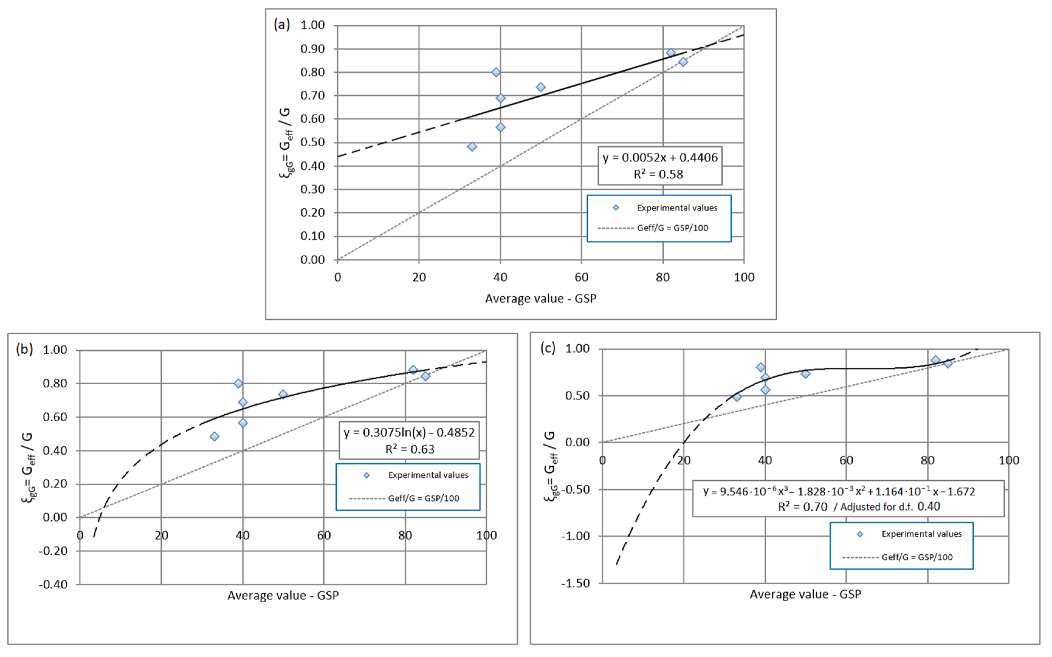
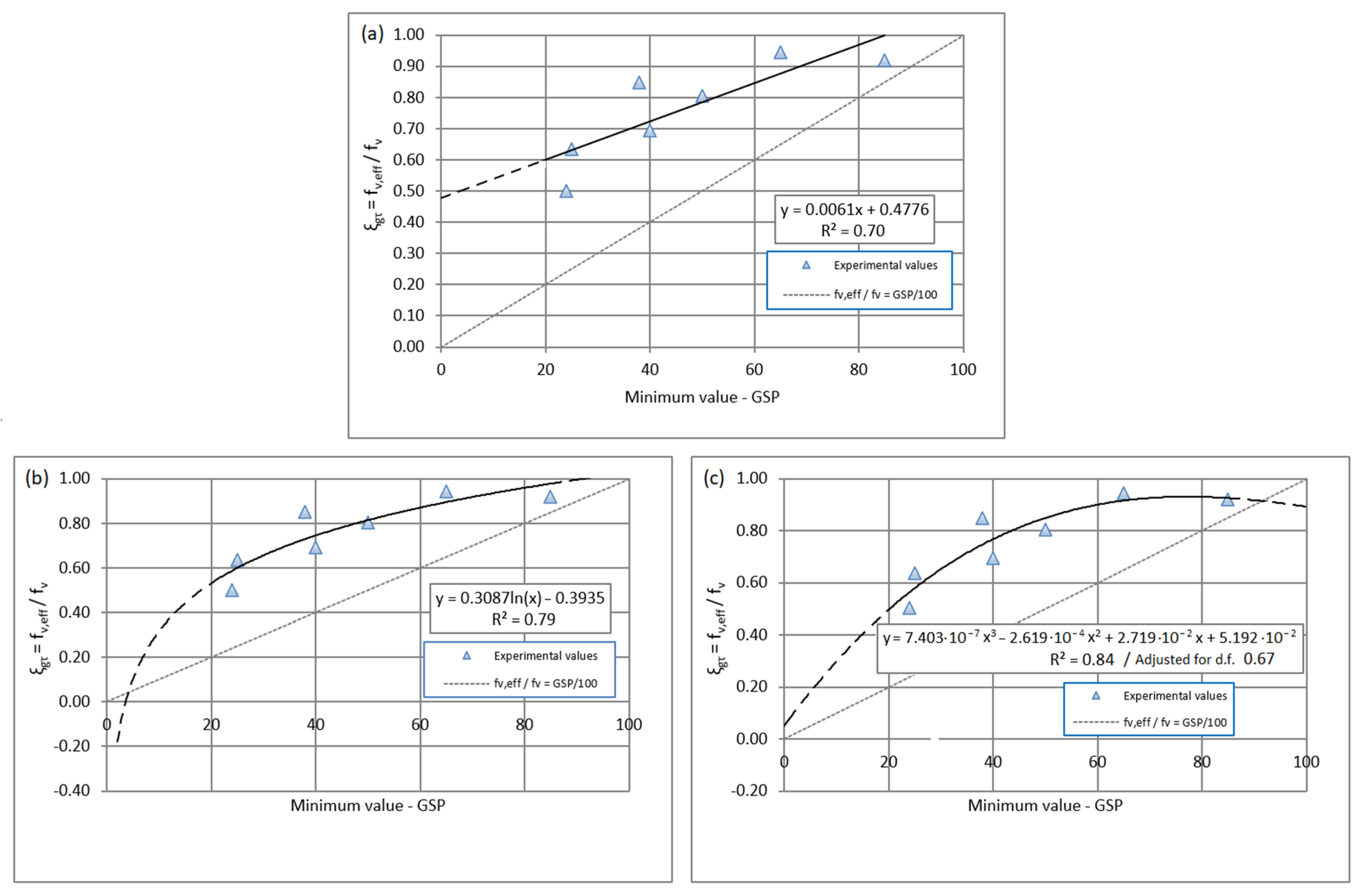
Figure 9 shows the scatter plots of test results for the transversal modulus of elasticity efficiency coefficient values obtained, defined in Section 2.4, versus the average GSP of the corresponding “A” specimen. Several different possible minimum quadratic regression models were assessed, with those presented in Figure 9 being those with the best fit. Figure 10 presents the same analysis for the shear strength efficiency coefficient values derived from the tests versus the mínimum GSP of the A specimens, corresponding to the failed surface.
All the models assessed in Figure 9 provide intermediate-high fit to the experimental data for the transversal modulus of elasticity efficiency, with the logarithmic and polynomial models being those with the highest determination coefficient, R2 between 0.63 and 0.70, although the polynomic result is the worst when considering the adjustment for the degree of freedom (R2 = 0.40).
Similar results are obtained in Figure 10 for the models that assess the relationship between the efficiency coefficient for the shear strength and the GSP, being the highest determination coefficient, R2 between 0.79 and 0.84, again for the logarithmic and polynomial models, again being the worst the polynomial model when considering the adjustment for the degree of freedom (R2 = 0.67).
The previous linear regressions were assessed by testing the requirements of linearity, homoscedasticity, independence, and normality (Shapiro–Wilk test and Kolmogorov–Smirnov test with p-value ≥ 0.05) of the variables using Statgraphics software [30]. The normality of the X variable of Figure 9 regression did not pass the Shapiro–Wilk test but fulfilled the requirements of the Kolmogorov–Smirnov test, which is considered the best assessment tool for samples with many close values as the one available in this case.
The p-values of the linear regressions were less than 0.05; therefore, there is a statistically significant relationship at the 95% confidence level. In some cases, a logarithm transformation in the independent variable and non-linear polynomial regressions of the variables was necessary to better fit the model, Figure 9 and Figure 10. Additionally, the polynomial regression in Figure 10 does not meet the autocorrelation p-value of the model (p-value = 0.107 > 0.05); in this case, the regression is used for comparison.
In order to identify the most suitable models, it would seem reasonable also to assert that the efficiency in both cases, transversal modulus of elasticity and shear strength, must approach 0 when GSP diminishes and gets closer to 0; furthermore, it must be 1 when GSP is equal to 100%, leading to the following considerations:
- although locally, the linear models fit the experimental values, it is evident that they are not going to fit in the case of the lowest GSP values, as a progressively decreasing ξgG and ξgτ is expected when GSP is diminished, being 0 when GSP equals 0;
- the logarithmic model presents a good fit, except for GSP values very close to 0 or for the highest GSP values;
- the third-order polynomial model shows a slightly better R2 value than the logarithmic model, although it worsens once adjusted for the degree of freedom. The shape of the model is closer to the expected behavior, except, again, at very high and especially at low GSP values.
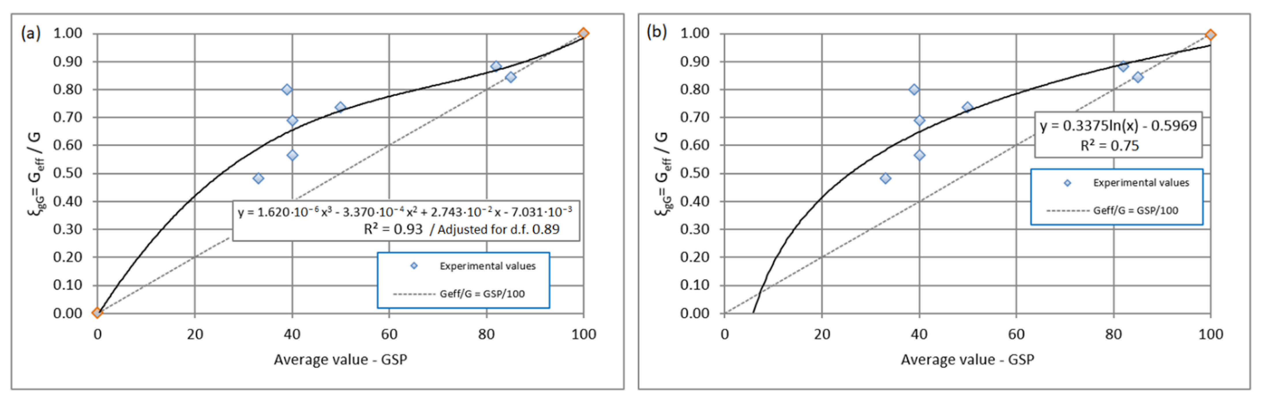
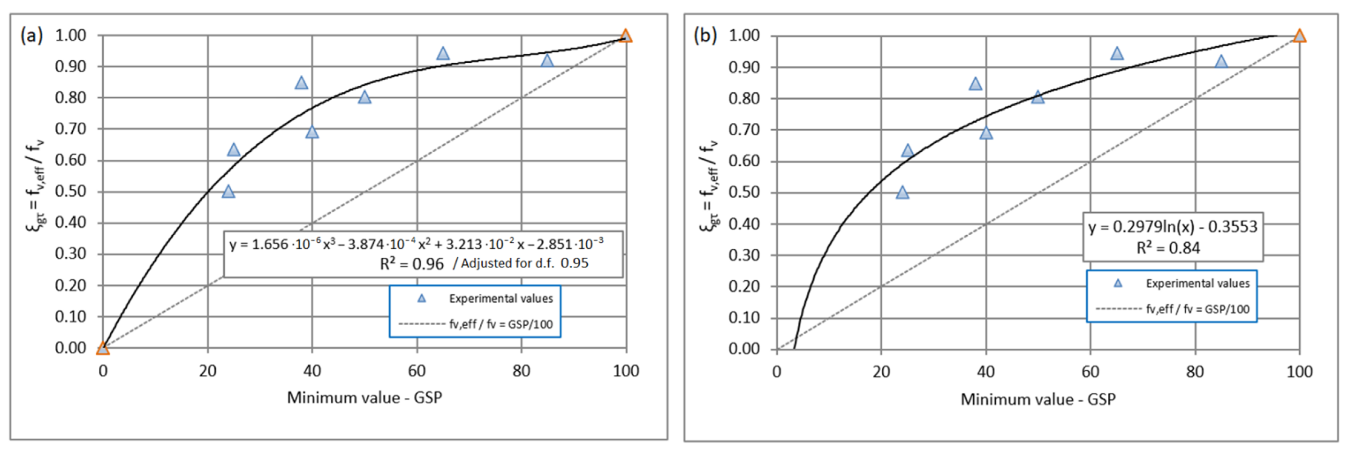
If an adjustment is made to the logarithmic and third-order polynomial models previously assessed (since these can be considered those with the best fit in terms of shape to the expected behavior), a clear improvement in the models can be observed.
The adjustment consists of entering the following expected values as additional data:
- ξgG = 1 or ξgτ = 1 for GSP = 100 in the logarithmic model;
- ξgG = 0 or ξgτ = 0 for GSP = 0 and ξgG = 1 or ξgτ = 1 for GSP = 100 in the third-order polynomial model.
Through these adjustments, new and better-fitting models are obtained, see Figure 11 and Figure 12. These models have a high determination coefficient and fit the expected function shape, the best being the third-order polynomial model due to its higher determination and a better description of the values close to 0 and 100% GSP. The p-values of the linear regressions were less than 0.05; therefore, there is a statistically significant relationship at the 95% confidence level.
As can be seen in Figure 11 and Figure 12, the transversal modulus of elasticity and the shear strength of the “A” specimens, considered through the efficiency coefficients, are related to the GSP value.
The tests showed mechanical values that were greater than those that would be expected if the foam was only working in proportion to the area of glued surface since most of the experimental values are in scatter plots above the line that fulfills this condition, Equation (7). This could be explained by the contribution of the non-glued areas of foam next to the glued areas in the shear stresses.
The values of both efficiency coefficients assessed are seen to separate more from the values corresponding to the proportion line that follows Equation (7) in the intermediate GSP values. These values are closer to Equation (7) at higher GSP values, and this may be explained by the proportional reduction in the contribution of the foam areas next to the glued areas when these glued areas are closer together.
The behavior at low GSP is expected to be similar to that observed at high GSP values, with the experimental data being closer to the Equation (7) line for GSP nearing 0, as it seems reasonable to expect that the contribution of the adjoining areas will be lower in proportion as the glued surfaces become more separated. However, to confirm whether this is indeed the case, further testing with lower GSP than those included in the study would be needed.
Shear strength values in wood-glued elements are expected to change with the size of the specimen [31], which can lead to doubts regarding the assessment of this property depending on the test method chosen. However, in this case, the shear mechanical efficiency of the panels has been assessed using the same methodology and specimen size used to obtain the declared shear properties of the insulation core material, which has proven to be adequate for use in bending models for wood-based sandwich panels [28].
4. Conclusions
The tensile tests proved to be suitable only for those panels with adequate skin material cohesion, such as wood and particleboard skins, its functionality as a control method improved when using the glued surface percentage (GSP) assessment together with the tensile strength. This test was useful to assess the variability of the results and, thus, the homogeneity of the adhesive performance under tensile stresses, as well as the glued surface percentage.
Mechanical efficiency coefficients for incompletely bonded sandwich panels were defined, together with an adapted experimental shear test method used to obtain them, concluding that the shear performance is clearly related to the percentage of glued surface.
The results of the shear tests provided non-linear models relating the effect of the glued surface with the mechanical properties, revealing that the mechanical efficiency of the incompletely bonded specimens is better than would be expected if the foam was only working in proportion to the glued surface, due to the fact that it is aided by the adjoining non-glued core material.
The optimum mechanical efficiency related to the bonded surface used was reached at intermediate glued surface percentages, although it was also associated with bonding failures and a smaller shear performance than that expected for the fully bonded specimens.
The present study is an initial exploration of the quality control effects associated with skin cohesion and of the mechanical performance of the incompletely bonded wood-based sandwich panels. More research is necessary, including testing of panels with other skin materials, adhesives, and core types, the latter with different densities, in order to confirm the tendencies observed and models obtained and define more detailed models for different core and face materials.
For full-size panels in bending the use of the efficiency analyses and models for incompletely bonded faces obtained in this research would require more investigation and that the bonding pattern is kept homogenously throughout the face-core surface of such panels; therefore, the quality control on the bonding homogeneity and strength remains as an important topic.
Other important aspects, such as durability related to time and climatic condition variations, are not addressed in this research, requiring further analyses.
Author Contributions
Conceptualization, E.H. and E.L.; methodology, F.A. and E.L.; software, E.L.; validation, E.H., F.A., I.B. and E.L.; formal analysis, E.H., F.A. and I.B.; investigation, E.L.; resources, E.H.; data curation, E.L.; writing—original draft preparation, E.L.; writing—review and editing, E.H., F.A. and I.B.; visualization, E.L.; supervision, E.H., F.A. and E.L.; project administration, E.H. and E.L. All authors have read and agreed to the published version of the manuscript.
Funding
This research received no external funding, with exception of part of the APC which is partially funded by Universidad Politécnica de Madrid (OTT-VAGI23FAM).
Data Availability Statement
Not applicable.
Acknowledgments
To the staff of the Construction Wood Products laboratory belonging to the ICIFOR-INIA Institute (CSIC) for their work and support and to José Chuliá for his help.
Conflicts of Interest
The authors declare no conflict of interest.
References
- ETAG 016—Part 1, Guideline for European Technical Approval of Self-Supporting Composite Lightweight Panels. Part 1: General; European Organisation for Technical Assessment: Brussels, Belgium, 2003.
- Zenkert, D. Strength of sandwich beams with mid-plane debondings in the core. Compos. Struct. 1990, 15, 279–299. [Google Scholar] [CrossRef]
- Burton, W.S.; Noor, A.K. Structural analysis of the adhesive bond in a honeycomb core sandwich panel. Finite Elem. Anal. Des. 1997, 26, 213–227. [Google Scholar] [CrossRef]
- Triantafillou, T.C.; Gibson, L.J. Debonding in foam-core sandwich panels. Mater. Struct. 1989, 22, 64–69. [Google Scholar] [CrossRef]
- Fernández-Cabo, J.L.; Majano-Majano, A.; San Salvador, L.; Ávila, M. Development of a novel façade sandwich panel with low-density wood fibres core and wood-based panels as faces. Holz. Als. Roh. Werkst. 2010, 69, 459–470. [Google Scholar] [CrossRef] [Green Version]
- Estrada-Martínez, S. Durabilidad, Bajo Condiciones Climáticas, del Panel Compuesto Ligero Autoportante, Tipo Sándwich, de Caras Derivadas de la Madera, que se Emplea Como Sistema de Cerramiento de Cubiertas. Ph.D. Thesis, Universidad de Oviedo, Asturias, Spain, 2012. [Google Scholar]
- Heebink, B.G.; Mohaupt, A.A. Investigation of Methods of Inspecting Bonds between Cores and Faces of Sandwich Panels of the Aircraft Type; Report 1569; Forest Products Laboratory: Madison, WI, USA, 1947. [Google Scholar]
- Norris, C.B. Effect of Unbonded Joints in an Aluminum Honeycomb-Core Material for Sandwich Constructions; Report 1835; Forest Products Laboratory: Madison, WI, USA, 1952. [Google Scholar]
- EASA. Final Report EASA_REP_RESEA_2016_2 for the Research Project: Disbond of Sandwich Structures—DoSS.; European Union Aviation Safety Agency: Cologne, France, 2017. [Google Scholar]
- CIB/ECCS. European Recommendations for Sandwich Panels. Part I: Design; CIB Report, Publication 257; International Council for Research and Innovation in Building and Construction: Kanata, ON, Canada, 2000. [Google Scholar]
- EN 14509; Self-Supporting Double Skin Metal Faced Insulating Panels—Factory Made Products—Specifications. European Committee for Standardization, CEN: Brussels, Belgium, 2013.
- ANSI/APA PRS 610.1; Standard for Performance-Rated Structural Insulated Panels in Wall Applications. American Plywood Association: Tacoma, WA, USA, 2018.
- EAD 140022-00-0304; Prefabricated Wood-Based Loadbearing Stressed Skin Panels. European Assessment Document. European Organisation for Technical Assessment; EOTA: Brussels, Belgium, 2018.
- FPL. Methods for Conducting Mechanical Tests of Sandwich Construction at Normal Temperatures; Report 1556, revised; Forest Products Laboratory: Madison, WI, USA, 1950. [Google Scholar]
- Negro, F.; Bigando, R.; Ruffinatto, F.; Zanuttini, R. Technical Assessment of the bonding quality of composite plywood with a thin cork core. Forests 2022, 13, 1839. [Google Scholar] [CrossRef]
- Zenkert, D.; Shipsha, A.; Bull, P.; Hayman, B. Damage tolerance assessment of composite sandwich panels with localised damage. Compos. Sci. Technol. 2005, 65, 2597–2611. [Google Scholar] [CrossRef] [Green Version]
- Funari, M.F.; Greco, F.; Lonetti, P. Sandwich Panels under Interfacial Debonding Mechanisms. Compos. Struct. 2018, 203, 310–320. [Google Scholar] [CrossRef]
- Mohammadi, M.S.; Nairn, J.A. Balsa sandwich composite fracture study: Comparison of laminated to solid balsa core materials and debonding from thick balsa core materials. Compos. B. Eng. 2017, 122, 165–172. [Google Scholar] [CrossRef]
- Avilés, F.; Carlsson, L.A. Analysis of the sandwich DCB specimen for debond characterization. Eng. Fract. Mech. 2008, 75, 153–168. [Google Scholar] [CrossRef]
- Saeid, A.A.; Donaldson, S.L. Experimental and finite element evaluations of debonding in composite sandwich structure with core thickness variations. Adv. Mech. Eng. 2016, 8, 1687814016667418. [Google Scholar] [CrossRef]
- Fatima, N.S.; Dhaliwal, G.S.; Newaz, G. Contribution of adhesive-reinforced interface on the performance of light-weight sustainable sandwich composites. J. Compos. Mater. 2022, 56, 1829–1849. [Google Scholar] [CrossRef]
- Garrido, M.; Correia, J.R.; Keller, T.; Branco, F.A. Adhesively bonded connections between composite sandwich floor panels for buiding rehabilitation. Compos. Struct. 2015, 134, 255–268. [Google Scholar] [CrossRef]
- Pereira, A.B.; Fernandes, F.A. Sandwich Panels Bond with Advanced Adhesive Films. J. Compos. Sci. 2019, 3, 79. [Google Scholar] [CrossRef] [Green Version]
- Köhler, R.; Jurisch, M.; Mayer, A.K.; Mai, C.; Viöl, W. Loofah Sandwich Panels: The Effect of Adhesive Content on Mechanical and Physical Properties. Materials 2022, 15, 7129. [Google Scholar] [CrossRef] [PubMed]
- Davies, J.M. Lightweight Sandwich Construction; Blackwell Science Ltd.: Oxford, UK, 2011; p. 161. [Google Scholar]
- Carlsson, L.A.; Kardomateas, G.A. Structural and Failure Mechanics of Sandwich Composites. In Series Solid Mechanics and Its Applications; Springer Science + Business Media, B.V.: Berlin/Heidelberg, Germany, 2011; Volume 121, p. 32. [Google Scholar]
- Jacques, E.; Makar, J. Behaviour of structural insulated panels (SIPs) subjected to short-term out-of-plane transverse loads. Can. J. Civ. Eng. 2019, 46, 858–869. [Google Scholar] [CrossRef]
- Luengo, E. Evaluación de Modelos de Cálculo y Comportamiento a Flexión de Paneles Sándwich de Madera de Fabricación Española. Ph.D. Thesis, Universidad Politécnica de Madrid, Madrid, Spain, 2022. [Google Scholar]
- EN 12090; Thermal Insulating Products for Building Applications. Determination of Shear Behaviour. European Comitee for Standarditazion, CEN: Brussels, Belgium, 2013.
- Statgraphics. Centurion XVI Version 16.2.04. 1982–2013; StatPoint Technologies, Inc.: Warrenton, VI, USA, 2013. [Google Scholar]
- Luengo, E.; Hermoso, E.; Cabrero, J.C.; Arriaga, F. Bonding strength test method assessment for Cross-Laminated Timber Derived Stressed-Skin Panels. Mater. Struct. 2017, 50, 204. [Google Scholar]
Figure 1.
Plan drawing. General layout for test specimen cutting in a sandwich panel section with a length of 1200 mm (half panel). Ti tensile test and A, B, and C shear test specimens.
Figure 1.
Plan drawing. General layout for test specimen cutting in a sandwich panel section with a length of 1200 mm (half panel). Ti tensile test and A, B, and C shear test specimens.

Figure 2.
Tensile test with load perpendicular to the skins. (a), elevation diagram; (b), test at the moment of initial failure.
Figure 2.
Tensile test with load perpendicular to the skins. (a), elevation diagram; (b), test at the moment of initial failure.

Figure 3.
(a) “A” specimen shear test set, including the skins, for testing the core and bonding performance; (b) “B” specimen test set, panel core fully glued; (c) “C” specimen test set, sandwich with skins reduced in thickness. F representing the load aplied to the set.
Figure 3.
(a) “A” specimen shear test set, including the skins, for testing the core and bonding performance; (b) “B” specimen test set, panel core fully glued; (c) “C” specimen test set, sandwich with skins reduced in thickness. F representing the load aplied to the set.

Figure 4.
(a) “A” specimen shear test set, a sandwich panel including the skins glued to the core; (b) “B” specimen shear test set, core material directly glued to the metal plates.
Figure 4.
(a) “A” specimen shear test set, a sandwich panel including the skins glued to the core; (b) “B” specimen shear test set, core material directly glued to the metal plates.

Figure 5.
(a), sandwich specimen with skin-to-core incompletely glued area, depicted in grey, and its effective shear performance parameters; (b), specimen with fully glued area and its shear performance parameters. See text after equations 3 and 6 for information on the parameters included in the images.

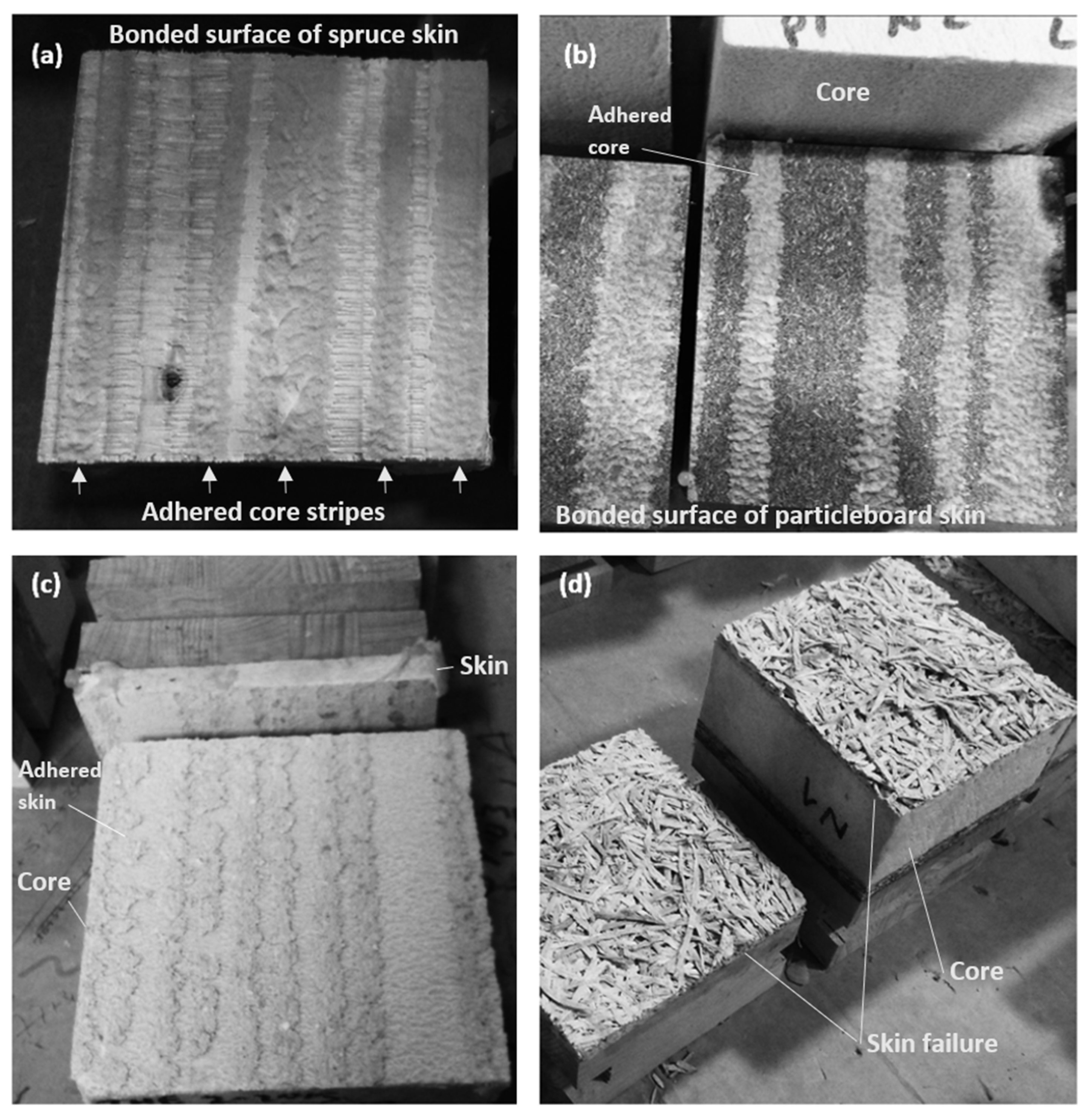
Figure 6.
(a,b), tensile to the skin failure on the bonded surface, incomplete bonding failures with core material adhered to the skin; (c) incomplete bonding failure with skin material adhered to the core; (d) failure in the skin material due to low cohesivity.
Figure 6.
(a,b), tensile to the skin failure on the bonded surface, incomplete bonding failures with core material adhered to the skin; (c) incomplete bonding failure with skin material adhered to the core; (d) failure in the skin material due to low cohesivity.

Figure 7.
Results of tensile tests with load perpendicular to the skin, strength vs. GSP, (a) for two different particleboard and solid wood skins sandwich panels from different batches; (b) for one of the previously shown particleboard and solid wood sandwich panels and for a particleboard and gypsum–fiber board sandwich.

Figure 8.
“A” Specimen examples of incompletely bonded surfaces after testing in shear.

Figure 9.
Regression model assessment for the transversal modulus of elasticity efficiency coefficient ξgG vs. the glued surface percentage (GSP) on shear experimental values. (a) Linear; (b) logarithmic; (c) third-order polynomial.
Figure 9.
Regression model assessment for the transversal modulus of elasticity efficiency coefficient ξgG vs. the glued surface percentage (GSP) on shear experimental values. (a) Linear; (b) logarithmic; (c) third-order polynomial.

Figure 10.
Regression model assessment for shear strength efficiency coefficient ξgτ vs. the glued surface percentage (GSP) on shear experimental values. (a) Linear; (b) logarithmic; (c) third-order polynomial.
Figure 10.
Regression model assessment for shear strength efficiency coefficient ξgτ vs. the glued surface percentage (GSP) on shear experimental values. (a) Linear; (b) logarithmic; (c) third-order polynomial.

Figure 11.
Adjusted models for the efficiency coefficient ξgG vs. the glued surface percentage (GSP) shear experimental values (blue) and expected values (orange). (a) third-order polynomial; (b) logarithmic model.
Figure 11.
Adjusted models for the efficiency coefficient ξgG vs. the glued surface percentage (GSP) shear experimental values (blue) and expected values (orange). (a) third-order polynomial; (b) logarithmic model.

Figure 12.
Adjusted models for the efficiency coefficient ξgτ vs. the glued surface percentage (GSP) shear experimental values (blue) and expected values (orange). (a) third-order polynomial; (b) logarithmic model.
Figure 12.
Adjusted models for the efficiency coefficient ξgτ vs. the glued surface percentage (GSP) shear experimental values (blue) and expected values (orange). (a) third-order polynomial; (b) logarithmic model.


Table 1.
Panels and specimens for tensile tests with load perpendicular to the skins and shear tests.
Table 1.
Panels and specimens for tensile tests with load perpendicular to the skins and shear tests.
| Panel Type a,b | Batch | Panels Sampled | Tensile Perpendicular Test | Shear Tests | ||
|---|---|---|---|---|---|---|
| No. Tests per Panel | Specimen Dimensions (mm) | No. Tests per Panel | Specimen Dimensions (mm) | |||
| PB19-XPS40-SB19 | 1 | 4 | 3 | 100 × 100 | 1 b + 1 c + 1 d | 100 × 200 |
| PB16-XPS50-SB10 | 2 | 3 | 3 | 68 × 68 e | 1 b + 1 c | 75 e × 200 |
| PB10-XPS40-GF10 | 1 | 3 | 3 | 100 × 100 | - | - |
| PB10-XPS40-CW10 | 1 | 3 | 3 | 100 × 100 | - | - |
a PB, particleboard; XPS, extruded polystyrene foam; SB, spruce boards; GF, gypsum-fiber board; CW, cement-wood wool board. Material code followed by its thickness in mm. b Commercial panels with incompletely bonded core (factory bonding). c Completely bonded core (bonding process performed in the laboratory), used for shear efficiency analysis. d Commercial panels with incompletely bonded cores (factory bonding) and laboratory face thickness reduction, used for face mechanical effect verification. e Panel face composed of boards with flat surfaces of less than 100 mm width, requiring the specimen width to be reduced from the recommended 100 mm.
Table 2.
Tensile tests. Average and scatter results of incompletely bonded panels.
| Panel Type | No. of Tests a | ft | GSP | ||
|---|---|---|---|---|---|
| Average (N/mm2) | CoV (%) | Average (%) | CoV (%) | ||
| PB19-XPS-SB19 | 12 | 0.21 | 46.5 | 46 | 37.1 |
| PB16-XPS-SB10 | 9 | 0.25 | 53.3 | 69 | 30.3 |
| PB10-XPS-GF10 | 8 b | 0.14 | 25.5 | 51 | 18.6 |
| PB10-XPS-CW15 | 9 | 0.07 | 26.7 | - c | - |
a The number of tests depends on the number of panels sampled for each type, 3 or 4, taking into account that 3 specimens were obtained per panel. b One specimen was discarded due to problems in the execution of the test. c Failure in the skin material due to lack of internal coherence.
Table 3.
Shear tests. Average and scatter results of the test with A, B, and C specimens.
| Panel Type | No. of Tests | A Specimens a | B Specimens a | C Specimens a | ||||||
|---|---|---|---|---|---|---|---|---|---|---|
| G (N/mm2) | fv (N/mm2) | GSP (%) | G (N/mm2) | fv (N/mm2) | GSP (%) | G (N/mm2) | fv (N/mm2) | GSP (%) | ||
| PB19-XPS-SB19 | 12 b | 3.98 [15.9%] | 0.17 [21.8%] | 38 [8.9%] d | 6.37 [11.7%] | 0.25 [4.2%] | 100 | 4.17 [10.6] | 0.17 [11.5%] | 41 [5.7%] |
| PB16-XPS-SB10 | 6 c | 5.92 [9.3%] | 0.23 [13.7%] | 72 [26.8%] d | 7.22 [0.5%] | 0.26 [5.9%] | 100 | - | - | - |
a Average values. The figures in brackets represent the coefficient of variation of the results. b 4 panels, 1 test set per panel and specimen type, 3 specimen types. c 3 panels, 1 test set per panel and specimen type, 2 specimen types. d CoV for average GSP, the CoV value for minimum GSP is a 26.5% for the PB19-XPS-SB19 panel type and a 26.3% for the PB16-XPS-SB10 type.
Disclaimer/Publisher’s Note: The statements, opinions and data contained in all publications are solely those of the individual author(s) and contributor(s) and not of MDPI and/or the editor(s). MDPI and/or the editor(s) disclaim responsibility for any injury to people or property resulting from any ideas, methods, instructions or products referred to in the content. |
© 2023 by the authors. Licensee MDPI, Basel, Switzerland. This article is an open access article distributed under the terms and conditions of the Creative Commons Attribution (CC BY) license (https://creativecommons.org/licenses/by/4.0/).
Share and Cite
MDPI and ACS Style
Luengo, E.; Arriaga, F.; Bobadilla, I.; Hermoso, E. Mechanical Efficiency and Quality Control Preliminary Analysis of Incompletely Bonded Wood-Based Sandwich Panels. Forests 2023, 14, 1074. https://doi.org/10.3390/f14061074
AMA Style
Luengo E, Arriaga F, Bobadilla I, Hermoso E. Mechanical Efficiency and Quality Control Preliminary Analysis of Incompletely Bonded Wood-Based Sandwich Panels. Forests. 2023; 14(6):1074. https://doi.org/10.3390/f14061074
Chicago/Turabian StyleLuengo, Emilio, Francisco Arriaga, Ignacio Bobadilla, and Eva Hermoso. 2023. "Mechanical Efficiency and Quality Control Preliminary Analysis of Incompletely Bonded Wood-Based Sandwich Panels" Forests 14, no. 6: 1074. https://doi.org/10.3390/f14061074
Note that from the first issue of 2016, this journal uses article numbers instead of page numbers. See further details here.