
Energy Distribution in Dowel-Type Joints in Timber Structures When Using Expansive Kits
by
 , , and
Jose G. Fueyo
1 ,
,
Jose A. Cabezas
2,
Manuel Domínguez
1,
Natividad Antón
3 and
Alberto Villarino
4,* 1
Department of Mechanical Engineering, High Polytechnic School of Zamora, University of Salamanca, Avda. Requejo 33, 49022 Zamora, Spain
2
Department of Mechanical Engineering, Faculty of Sciences, University of Salamanca, Plaza de la Merced s/n, 37008 Salamanca, Spain
3
Department of Construction and Agronomy, Materials Science and Metallurgical Engineering Area, High Polytechnic School of Zamora, University of Salamanca, Avda. Requejo 33, 49022 Zamora, Spain
4
Department of Construction and Agronomy, Construction Engineering Area, High Polytechnic School of Ávila, University of Salamanca, Hornos Caleros 50, 05003 Ávila, Spain
*
Author to whom correspondence should be addressed.
Forests 2021, 12(9), 1200; https://doi.org/10.3390/f12091200
Submission received: 5 August 2021
/
Revised: 26 August 2021
/
Accepted: 30 August 2021
/
Published: 3 September 2021
(This article belongs to the Special Issue Wood as Biomechanical Structure)
Abstract
:This paper provides a study of the mechanical energy distribution in dowel-type joints in timber structures when using expansive kits. The compression caused by the expansive kit increases the friction between the dowel and the timber’s hole, opposing the longitudinal sliding that occurs during the bending of the dowel. The ensuing rope effect increases the load capacity of the joint. The aim was to determine the advantages and disadvantages of using this kind of reinforcement. For this purpose, an ad hoc finite element model of the joint was prepared taking the contact between the different components of the joint into account and appropriately simulating the radial expansion of the dowel and the behavior of the timber. The model was checked for accuracy by comparing the results with those coming from a set of experimental tests. After that, the model was used to verify that the use of the expansive kit reinforcement leads to a slight improvement in the load capacity of the joint. This improvement is related to the frictional forces, whose effect is especially significant at low levels of joint displacement.
1. Introduction
Wood has been used as a construction material for thousands of years, until the twentieth century, when its importance in this field was eclipsed by the appearance and development of other materials such as steel and concrete. Nevertheless, advances in new and more resistant wood-based materials characterized by environmental advantages, improved durability and resistance to aggressive environments, and earthquake resistance [1] have renewed interest in the construction of timber structures, which have definitely increased in number.
One of the most widely used wood-based products is structural laminated wood. This is formed by gluing several wood layers arranged in the direction of the grain [2]. The gluing is done with adhesives such as polyurethane and is formed in a pressing process described in the standard [3]. According to the standards [4], the wood species suitable for the manufacture of structural laminated wood are Norway spruce (Picea abies) [5,6], silver fir (Abies alba) [7], Scots pine (Pinus sylvestris) [8], Oregon pine (Pseudotsuga menziesii), black pine (Pinus nigra), European larch (Larix decidua), maritime pine (Pinus pinaster) [9], poplar (Populus robusta, Populus alba), radiata pine (Pinus radiata) [10], Sitka spruce (Picea sitchensis), western hemlock (Tsuga heterophylla) [11], western red cedar (Thuja plicata) and yellow cedar (Chamaecyparis nootkatensis).
As with other kinds of structures, the joints of timber structures are always one of their weakest points [12]. Indeed, the strength of the joints usually defines the load-carrying capacity of the whole structure, which is why understanding their mechanical behavior is a matter of paramount importance to structural designers and engineers in order to improve their structural possibilities and prevent them from limiting the structure’s strength [13,14].
Among all the possible kinds of joints used in timber structures, dowel-type joints are one of the most common connectors [15]. They basically consist of one or more cylindrical steel dowels inserted into aligned holes of different elements. The dowels transmit loads between the elements, being subjected to opposite compressive forces on the contact area with each element. This causes the dowels to work under bending moments and shear forces. There is an almost infinite number of possible configurations for dowel-type joints. For example, they can connect two, three or more timber [16], or even steel members [17,18]. Not only a single dowel, but also a combination of dowels can be used, in line or in a matrix distribution [19]. The dowels can work in a single or double shear. Finally, dowel action can be reinforced through different techniques: adhesives [20,21], split rings or shear plate connectors [22]. Another form of reinforcement is the expansive kit, which is of particular interest as a subject for study because of its intensive use and high performance with steel and concrete [23,24,25], the other two main materials used for large constructions. Especially in concrete, expansive joints have been an improvement when evolved to prefabricated kits, which have many advantages [26,27]: they allow quick and easy assembly in construction, reduce repair costs, obviate the need for reconditioning work or “on-site” adjustments at the joint and offer a permanent solution and, in certain cases, are reusable. In timber structures, an expansive system has been investigated in dowels constituted by overlength hollow steel tubes expanded by compression of the tube ends [28].
Therefore, it is reasonable to think that a controlled expansion of a solid dowel in a timber joint could also provide several advantages [28]: increasing the load-carrying capacity of the joint, reducing slippage of the joint, thereby increasing its stiffness, and improving the distribution of stresses in the timber parts along the hole where the dowel is located.
A study of the distribution of mechanical energy in timber dowel-type joints has been conducted to determine the advantages of using expansive kits in them. To achieve this goal, a finite element model of a joint was prepared, which included: contact between the surfaces of the dowel and those of the timber part holes, a system to simulate the effect of the expansive kit, and an ad hoc three-dimensional anisotropic elastoplastic mechanical model to simulate the behavior of the timber. The accuracy of the model was checked against the results obtained from a set of experimental tests, within a broader program in which specimens of different geometries and the dowel’s typology are studied. The expansive kit used consisted of an expanded sleeve made of a hollow tube and a solid rod inserted into the sleeve. After an exhaustive search, no references have been found on the study of the distribution of mechanical energy in dowel-type joints in timber structures. Therefore, the analysis carried out can be considered totally innovative.
2. Materials and Methods
There are many factors that can affect the structural performance of dowel-type joints, such as the geometry of the joint and of the members it connects, the orientation of the grain in each member or the clearance and friction between the joint parts [29,30]. In their actual application, these factors can be combined in an almost infinite number of ways. For the purposes of the study, a real case with representative values of these variables was used.
2.1. Geometry of the Configuration
The case studied involves a dowel-type joint with only a steel element working in double shear. Its configuration, dimensions, and boundary conditions are shown in Figure 1. All these variables have been taken from a joint located on the real structure mentioned above.
2.2. Preliminary Materials Description
In order to evaluate the behavior and quality of the joint, the materials (sleeve/rod and timber) were first characterized. The different equipment used for this task are detailed below.
Macrographs were taken with a conventional digital camera (Casio model Exilim 12.1 Megapixels, Tokyo, Japan). A Celestron Handheld Digital Pro 5MP microscope (Torrance, CA, USA), equipped with white LED-type light, was also used to take photographs with medium magnification to see the general appearance of the materials. Samples of timber were polished using SiC sandpapers 220#, 500# and 1000#.
The moisture content was verified using a resistance xylohygrometric equipment, Seltar model HGD-1 (Barcelona, Spain), which ratifies the normative prescriptions and allows determining the moisture content during the tests [3,31].
Before the test specimens were prepared, the wood had to be kept in a wet chamber with an atmosphere with a relative humidity of 65 ± 5% and at a temperature of 20 ± 2 °C until a constant mass was achieved [2]. Once the specimen has been made, and prior to testing, the specimen assembly must be reconditioned in the same way. The density of the complete pieces was determined through weight, using a Kern model TB35K1 (max. 35 kg) equipment (Balingen, Germany), and geometrical measurements. Figure 2 shows a summary of the manufacture and preparation of the specimens.
To observe the microstructure of the steels used in the sleeve and rod, an optical microscope was employed. The micrographs were taken with a ZEISS Axiovert 100A microscope (Jena, Germany). The microscope has a digital camera, CCD model OPTIKAM B9 3MP (Ponteranica, Italy), controlled through Optika Vision Lite software. Previously, the samples were prepared using SiC sandpapers 220#, 500# and 1000# and a final polishing with a 0.1 micron diamond dispersion for metallographic observation. In order to observe the microstructure of the steels, a metallographic attack using 3% Nital (nitric acid in ethanol) was carried out. The previous tensile tests on the steels were carried out on a Universal Pressing Machine Model multi-test equipment, Nestor 10 Tn. max. (Madrid, Spain).
2.2.1. Timber
The timber used was graded as GL24h (type P. abies) according to Eurocode 5 (hereafter abbreviated as EC-5) [3]. It has its origin in Austria and was produced by Noritec Holzindustrie GmbH (Sachsenburg, Austria). Figure 3 and Figure 4 show the configuration of the glued laminated timber disposition and details of the polished wood, respectively; Table 1 displays the mean mechanical properties of the timber GL24h, obtained from the company Noritec Holzindustrie GmbH.
2.2.2. Steel
The sleeve (or tube) was made of ferritic steel F1110 (ST52) that can be used for elements that require great toughness and that must have a significant level of deformation. The average mechanical properties obtained are Young’s modulus Es = 205 GPa, Poisson’s ratio ν = 0.29, yield strength fy = 327 MPa and ultimate strength fu = 380 MPa. The selection of this type of steel will facilitate the expansion process due to its great ductility.
The rod was made of ferritic steel graded as S275JR [32] (non-alloy quality structural steel [33]). It was quenched and tempered. In addition, due to its low carbon content, its microstructure is especially ductile, being ferritic in its core. The hardened surface will facilitate the insertion of the rod into the sleeve without deterioration. Its average mechanical properties were obtained from tensile tests with the following values: Young’s modulus Es = 210 GPa, Poisson’s ratio ν = 0.3, yield strength fy = 443 MPa and ultimate strength fu = 521 MPa. Figure 5 shows a summary of the metallurgical characterization of the sleeve and rod.
2.3. Expansive Kit
To carry out the expansions, a hydraulic press equipment, Mega model KMG-30 (Pontevedra, Spain), was used. There are different methods to introduce the expansion effect [28,34]. After trying several of them, the one that seemed to be the most effective and easy to perform consisted of using a steel tube whose initial outer diameter was equal to that of the holes in the timber parts. To carry it out, all the joint parts were arranged in their final assembled position and the steel tube was expanded by using steel spheres with a larger diameter than the inner diameter of the steel tube and a press machine. The initial inner and outer diameters of the sleeve, 8.5 mm and 12.0 mm, were increased to 9.2 mm and 13.0 mm, respectively. The final step was the insertion of a solid steel rod to fill the interior of the steel tube. Figure 6 shows the sphere insertion.
3. Finite Element Model
The finite element model was prepared according to the geometry, materials and loads described in the above section. The model was meshed using a combination of eight, six- and four-node volume elements (called C3D8, C3D8 and C3D4, respectively, in Abaqus). The model has 5820 elements and 8952 nodes. The model also has five parts: rod, sleeve, block, central and lateral parts. A nonlinear analysis was performed in order to take into account the evolution of the contact between the sleeve and the timber parts and the elastoplastic mechanical behavior of both materials, timber and steel. Figure 7 shows the complete model, only a quarter of which has been meshed, benefiting from the existence of two perpendicular planes of symmetry.
Since the development of the finite element model requires accurate specification of the directions that define the timber’s orthotropic behavior, it is necessary to consider different local coordinate systems adapted to the direction of the grain in each of the model’s timber parts. Figure 7 shows the coordinate systems used: a global one (G), three for each of the three timber parts, the central, lateral and block parts, defined as C, L and B, respectively, and a cylindrical one to study the strains and stresses in the dowel (D).
3.1. Contact Zone
The contact zone was modelled using the so-called hard formulation. In FEM contact models, the algorithm that controls the possible contact between a pair of solids requires that part of the surface of one of the solids must be defined as the master surface, and the corresponding surface of the other solid as the slave surface. The algorithm prevents the nodes of the slave surface from penetrating the master surface [15]. Moreover, it defines the force transmission between nodes when a slave surface node makes contact with the faces constructed with the master surface nodes. This force follows a step function that goes from zero, before contact, to the required value, after contact has been detected. Careful selection of mesh type and size is essential to obtain accurate contact results.
3.2. Steel and Timber Behavior Models
Steel was modelled as a homogeneous isotropic material with a 3D elastoplastic behavior described by the von Mises criterion [35], considering an effective stress-strain curve with a simplified trilinear shape [36] (symmetrical in tension and compression), with the values obtained from the results of uniaxial tests, as can be seen in Figure 8a. While the effective stress is lower than yield strength fy it behaves as linear elastic; beyond this point, the plastic flow with isotropic hardening develops until ultimate strength fu is reached, after which its behavior becomes perfectly plastic.
The mechanical behavior of wood is especially difficult to simulate due to its anisotropy, which implies different elastic moduli and strengths in the different directions with respect to grain direction [37,38,39]; furthermore, the values of the latter characteristics change depending on whether it is subjected to compressive or tensile efforts. This strength asymmetry is a result of the different microscopic mechanisms that act on timber: there is fracture under tension [40] and buckling under compression in the direction of the grain, while separation of fibers under tension [41] and crushing under compression occurs in the direction perpendicular to the grain [42].
Figure 8b shows the simplified stress-strain curves considered in this work, obtained from the values indicated in Table 1, for the uniaxial behavior of the timber in the direction of the grain and perpendicular to it. The different values of the strengths in both curves and between the tension or compression branches of each one, and the different slopes of the linear elastic sections can be observed. As an approximation, and after overcoming the corresponding strengths, a perfectly plastic behavior is assumed. This results in large plastic deformations at small stress increases.
To simulate the 3D mechanical behavior of timber, it is especially important to choose a correct model that includes different values of the mechanical properties in tension or compression. Orthotropic elastoplastic models based on the Hill criterion are most widely used [39]. However, since Hill’s theory considers a symmetrical behavior in tension and compression, it is necessary to generalize it to include different characteristics of timber according to the type of effort acting on it.
3.3. User Material Subroutine for Timber
The material libraries of finite element commercial programs include the von Mises elastoplastic isotropic model, usually alongside Hill’s model for orthotropic behavior (e.g., in the program Abaqus used in this work, the latter is called Hill48), but they do not include orthotropic models that take into account the different strengths in tension and compression. However, ad hoc behavior models can be developed for most of them by using complementary procedures [43,44]. In Abaqus, this is done through user subroutines called UMAT, programmed in FORTRAN.
Therefore, the description of the complex mechanical behavior of timber required the development of a specific UMAT subroutine, which contains the programming of the incremental formulation of Hill’s elastoplastic model (performed following the steps indicated by certain authors [45]), but completed to use tensile or compressive strengths depending on the way in which the material is working at the analyzed point [46]. To determine how it works, the dimensionless ratios between the stresses and strengths in the three orthotropic directions are calculated, considering tensile strength if the stress is positive and compressive strength otherwise. Subsequently, the highest ratio in absolute value is determined and, if it is positive, the point is considered to work predominantly in tension; otherwise, it works in compression.
The subroutine includes the three basic stages required to define the 3D elastoplastic mechanical behavior: Hooke’s law of elastic behavior for orthotropic materials, Hill’s yield criterion to determine whether there is plastic deformation, and the associated flow rule to define the plastic behavior [47]. For each increment in deformation, Abaqus uses the subroutine at each integration point to obtain the final values of the stresses and strains after such an increment is ended. Figure 9 shows the flow chart for the subroutine. First of all, it determines whether the point is working in tension or in compression, calculating Hill´s constants with adequate strengths. Then, it assumes that the increment of deformation is elastic (elastic predictor), and the yield criterion is applied; if the criterion is not fulfilled, the increment is confirmed as elastic and the subroutine ends; otherwise the stresses and elastic and plastic strains are obtained by performing a calculation based on the flow rule (plastic corrector).
3.4. Expansion of the Dowel
After trying different ways to simulate the effect produced by the expansive kit, the procedure that seemed to have more advantages is based on exploiting the fact that finite element programs have clearly defined the mechanism of thermal expansion, which can be used to simulate the mechanical one provoked by the expansive kit. For this purpose, a thermal expansion coefficient was assigned to the rod, which was designed with an initial diameter equal to the inner diameter of the sleeve after the expansion produced by the spheres (Figure 6). A fictitious field of decreasing temperatures was established in the rod to contract it so that it could be inserted in the unexpanded steel tube that constitutes the sleeve. The second step was the elimination of the temperature field, so that the rod tries to recover its initial dimension, pushing the inner wall of the sleeve, which causes compression on the timber in the area surrounding the dowel and thus creating the expansion effect. Although this procedure seems more complicated than direct application of an expansion process, it is advantageous in that it is easier to work on the results because they do not accumulate the thermal deformations that would appear with a direct expansion process, which do not exist in the real procedure.
4. Experimental Tests
Some tests using expansive kits were performed within a broader campaign of dowel-type joint testing (with different timber classes, dimensions and reinforcement systems) conducted following European standards [48]. To carry out the tests, a Codein 30 t multi-test press, Model MCO-30 (Fuenlabrada, Madrid, Spain) was used. Three specimens, labelled S1, S2 and S3, all of them with same the geometry, materials, load and expansive kit described in Section 2.3, were used for the purpose of having several measures.
The part called block in Figure 1 does not exist in actual structures, but has been introduced in the experimental tests to prevent the lateral parts from coming together, since the separation distance between them should be equal to the width of the central part, as is the case with actual structures. Figure 10 shows a specimen in the testing machine. The results from these tests were used to check the results yielded by the different finite element models. In the FEM model, although the effect of the block could have been substituted by certain external displacement conditions, it was preserved for the sake of having greater similarity with the specimens.
5. Results and Discussion
According to the European standard EN 26891 [48], the test may be stopped when the applied load reaches the so-called estimated maximum value Fest, established on the basis of calculation or preliminary tests, or when the displacement reaches 15 mm.
The load-carrying capacity of the joint calculated following the EC-5 [3] (whose Section 8.2 is dedicated to the design of dowel-type joints), has been considered a reference value for Fest. For the dimensions and material properties of the case study, the calculation gives a load-carrying capacity per shear plane Fv,R = 6027 N, the failure mode involving the appearance of crushed areas at the ends of the holes of the timber parts and three plastic hinges in the dowel. So, in the case studied that presents two shear planes, the admissible load on the joint is 2.Fv,R, as shown in Figure 1, which is also the value considered for the estimated maximum value: Fest = 2.Fv,R = 12,054 N.
In the following sections, the results of the study for different variables are shown and discussed, comparing the experimental values with those obtained from finite elements.
5.1. Load vs. Displacement Comparison with and without the Expansive Kit
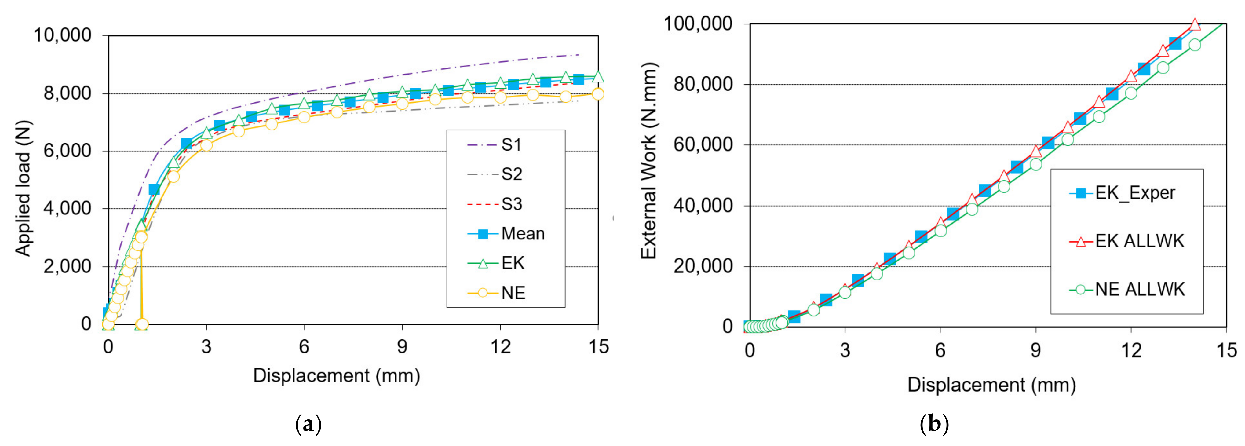
Figure 11a shows the load vs. displacement results yielded by the experimental tests and the FEM model, with and without the expansive kit. Both magnitudes are measured on the upper surface of the central timber part. Labels in Figure 11a indicate:
- EK: FEM model with the expansive kit used (final expanded diameter 13 mm).
- NE: FEM model without using the expansive kit.
- S1, S2 and S3: experimental results yielded by the three tested specimens.
- Mean: the curve obtained from the mean values of the three specimens.
The loads obtained from the testing machine’s sensors were divided by four, so that it could be compared with the results coming from the FEM models, where owing to the double symmetry, only a quarter of the joint was considered. Therefore, the corresponding value of the estimated maximum load would be Fest/4 = 3014 N.
For greater generality, the study has been carried out up to the situation that is later reached among those contemplated in the EN 26891 [48] mentioned above. Thus, a displacement of 15 mm has been reached, greatly exceeding the 3014 N of Fest/4, as can be seen in Figure 11a. Consequently, the 15 mm displacement condition has marked the limit in the subsequent studies carried out.
The shape of the curves coincides with those that appear in the literature [49] with a very inclined first part that begins with the segments called initial consolidation and first loading, an intermediate part called decrease of stiffness and an approximately flat final part named loading plateau. The same curves can be seen in the works of other authors such as [6,50,51]. This means that this type of joint has two clearly different stages, with two different tendencies or behaviors regarding their load capacities. During the first displacements (the so-called first loading stage), the joint is capable of significantly increasing its load capacity. On the other hand, from a certain level of displacement, the joint enters the loading plateau, which means that its load capacity hardly increases. This is the reason why, in Figure 11b, from 5 mm onwards, the external work curves are almost straight. Because the load capacity is almost constant, the displacement increase implies that the external work ALLWK grows in an almost linear way.
The curves in Figure 11b show the evolution of the external mechanical work when the displacement progresses. Its value at each increment for both FEM models is provided by the software under the acronym ALLWK (Abaqus 2019) [52]. The equation used to obtain its value at the end of each increment k from the experimental data is as follows:
where Fmean,i is the mean load in increment i, and Δdi is the displacement increment.
Two clear conclusions can be inferred from these results and their comparison. First, the prepared FEM models accurately match the experimental results. Second, the results of the two FEM models, with and without the expansive kit, lead to the deduction that the load capacity of the joint is slightly increased by the presence of the expansive kit. Figure 12 shows the energy distribution between the different joint parts (Figure 12a) and ratios between energies (Figure 12b). The value of this improvement along the 15 mm displacement range, considered according to EN26891 [48], can be observed in the curve EK_ALLWK/NE_ALLWK in Figure 12b, which represents the ratio between the indicated quantities. This curve is almost constant throughout the displacement range, with a mean value of 1.072; that is, the use of the expansive kit involves a 7.2% improvement.
5.2. Mechanical Energy Distribution between the Different Parts of the Joint
Taking advantage of the fact that the software used provides the values of the internal strain energy, known as ALLIE (Abaqus 2019) [52], a more exhaustive analysis was performed to determine how the mechanical energy is distributed between the parts of the joint, with and without using an expansive kit. In the case without expansive kit NE, the dowel also consisted of a sleeve and a rod with the same dimensions of the sleeve and the rod of the KE case after the expansion, so that the comparison with that case can be done, although in the NE case no expansion has been applied. Figure 12a shows the energy distribution in the different elements of both joints, with expansive kit KE, and without expansive kit NE, and Figure 12b some selected ratios between all these energies.
Figure 12a shows the great tendency of the lateral timber part to absorb energy in both cases NE and KE. The tendency to absorb energy in the central timber part is also remarkable, although not so big as in the case of the lateral timber part. The comparison of the curves EK_lateral and EK_central, which represent the mechanical energy of the central and lateral timber parts, shows that it is higher in the lateral part and that it increases further with displacement. More specifically, the curve EK_lateral/EK_central in Figure 12b shows that their ratio increases from 1.00 to 1.80 in the studied range of displacement, with a mean value of 1.48. As Figure 12a shows, in these parts, EK_lateral and EK_central, the mechanical energy does not vanish at zero displacement. The reason is that the energy resulting from the application of the expansive process already exists when there is no displacement.
The sleeve stores more energy than the rod. Both pieces are in great demand and work under all kinds of stresses: compressive, shear and bending. The latter type of stress plays the most relevant role in these parts of the joint, provoking the appearance of the hinges that define failure modes 3 and 4 proposed by EC-5 [3]. Because bending stresses follow Navier’s law, they are higher at the farthest points from the neutral axis. This causes the sleeve to contribute with more mechanical work per unit volume than the rod, although the section of both parts in the expanded configuration is almost the same (Arod = π × 9.22 = 265.9 mm2 and Asleeve = π × (132 − 9.22) = 265.0 mm2), the curve EK_sleeve/EK_rod in Figure 12b shows that the average contribution of the sleeve is 57% above that of the rod over the 15 mm displacement range and that this value is approximately constant along the whole interval.
The energy accumulated in the block is negligible. As commented above, this part of the joint was introduced in the experimental specimens and FEM models to prevent the lateral parts from coming together, and this analysis verifies that its energy contribution is not relevant, which is why no further information on this part of the joint will be provided.
Curves EK_FD and NE_FD in Figure 12a show the values of the variable ALLFD, which defines the frictional dissipation or, more precisely, the total energy dissipated through frictional effects in the whole model. In this case, the energy is dissipated through the friction between the surfaces of the holes in the timber parts and the sleeve. As can be seen in Figure 12a, the frictional dissipation mechanism helps to absorb almost the same energy in all the joints as the sleeve deformation, which denotes the importance of this mechanism. The use of the expansive kit increases friction and therefore increases the value of this variable. During the whole 15 mm displacement, the frictional dissipation in the EK case has been around 2500 N.mm bigger than in the NE case. Curve EK_ALLFD/NE_ALLFD in Figure 12b shows the ratio between the frictional dissipation energies with and without the expansive kit. When the displacement is small, the value of this ratio is very large (not shown in the figure because of its high value, which reaches 22.14 for a 1 mm displacement) because the applied load is small (Figure 11a) and, therefore, also the normal and friction forces produced by it. If the expansive kit is used, its relative contribution to normal and friction forces is then comparatively very large. The ratio decreases to 1.25 for a displacement of 15 mm. Its mean value over the full displacement range is 3.26. Increased displacement requires a higher applied load, which generates greater normal and friction forces, so that the contribution of the expansive kit is comparatively less.
The sum of all the internal mechanical energies must equal the total external work, ALLIE + ALLFD = ALLWK + ALLWKexp, where ALLWK is the work of the applied load, which has been shown in Figure 11b, and ALLWKexp is the work used to expand the sleeve when using the expansive kit. The external work must be equal to the sum of the internal work plus the frictional dissipation. The distribution of these energies at the final displacement, shown in Table 2, is as follows:
The curve EK_ALLWK/NE_ALLWK in Figure 12b shows the increase in the capacity to absorb energy of the case with expansive kit with respect to the case without expansive kit. The curve has an almost constant and plane tendency during the whole 15 mm displacement. This corresponds to the approximately 7% improvement previously indicated in Section 5.1.
5.3. Ratio between the Elastic and the Plastic Mechanical Energies
The software used provides the values of the elastic and plastic strain energies in each element through two variables, called ELSE and ELPD, respectively, and defined as
where and are the components of the stress tensor, and are the components of the elastic strain tensor and and are the components of the plastic strain rate tensor [53].
It is thus possible to obtain the elastic ESE and plastic PSE energies in every part of the model by adding the values of ELSE and ELPD of all the elements contained in that part. Figure 13a shows this information in the joint with the expansive kit for the different parts of the joint and Figure 13b the ratios between plastic PSE and elastic ESE energies in them.
For each part, the curves in Figure 13a correspond to the separation of the total internal strain energy (EK curves in Figure 12a) into elastic and plastic strain energies. In particular, the values in the lateral and central parts for zero displacement indicate the mechanical energy introduced by the expansive kit: in the central part the energy due to elastic strains is 6,000 N.m and the energy corresponding to plastic strains is 2,504 N.mm. The lateral part has almost the same values, 6,000 N.m and 2,534 N.mm, respectively, which is reasonable because the dimensions of the contact surfaces, materials and expansions are almost the same in both parts.
Figure 13b shows how zero displacement involves plastic strain energy in the timber parts, with a value equal to 41% of that corresponding to the elastic strain, due to the effect of the expansive kit. In contrast, plastic deformations do not appear in the sleeve until the displacement reaches 2.5 mm, requiring 3.0 mm to appear in the rod.
In the timber parts, the plastic energy exceeds the elastic energy from a displacement of 1.5 mm onwards, becoming 4.8 times higher in the lateral part and 3.8 times higher in the central part at the final displacement measure of 15 mm. Therefore, it can be deduced that, with increasing displacement, the tendency of the lateral part is to plasticize more than the central one. From a displacement of 10 mm onwards, the ratio PSE/ESE is around 25% greater in the lateral part than in the central part.
The plastic energy in the sleeve is greater than the elastic energy from 6.3 mm onwards, doubling the latter at 15 mm; while in the rod the ratio is 1.0 at 8.0 mm, reaching a value of 1.85 at 15 mm. Therefore, the sleeve tends to plasticize more than the rod, which is reasonable, since assembly constituted by the rod and the sleeve is subjected to high bending moments, and in it, the fibers of the sleeve are further away from the neutral fiber than those of the rod. Of the four parts, rod, sleeve, central and lateral, the one that shows the greatest tendency to plasticize by far is the lateral timber part as the curve “lateral PSE” in Figure 13a shows, followed by the central timber part. The plasticization in the sleeve and the rod is less significant, and it does not appear until a 2 and a 3 mm displacement, respectively.
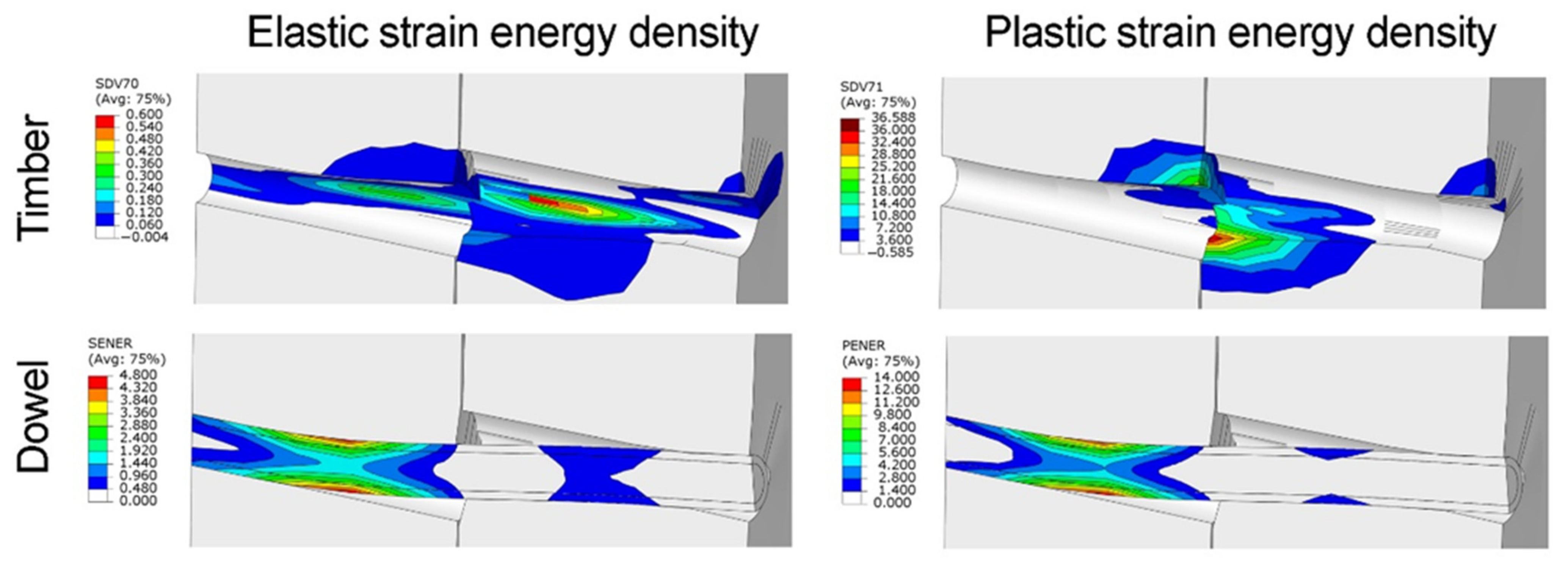
5.4. Study of the Energy Distribution inside the Timber Parts
Most of the energy studied above appears to be concentrated in very small zones in the timber parts and in the hinges of the rod and sleeve [54]. This is consistent with the proposal made by EC-5 [3], which situated the main plastic zones of failure modes 3 and 4 at these positions. This can be checked in Figure 14, which shows the results of variables SENER (elastic strain energy density) and PENER (plastic dissipation energy density). These variables are the equivalent of ELSE and ELPD, but they are calculated per unit volume instead of per element volume. These variables are only available in the steel parts, rod and sleeve, because the mechanical behavior of the timber parts has been calculated through the subroutine. In the subroutine some code lines have been added to calculate these energies through the solution-dependent state variables SDV70 (which is equivalent to SENER) and SDV71 (equivalent to PENER), respectively. Figure 14 represents all these variables when a 15 mm displacement in the x direction has been applied to the central timber part of the joint.
As can be seen in Figure 15, a deformation, elongation and breakage of the sleeve takes place while the internal rod resists the bending stresses, thanks to its surface quenching treatment as indicated in Section 2.2.2. The hardness of the martensitic microconstituent has facilitated the insertion of the rod in the sleeve and has helped to resist and transmit the stresses to the core of the rod, which is much more tenacious thanks to its ferritic microstructure. In the timber case, its behavior and deformations coincide with the results obtained from the finite element numerical study as shown in the lower right corner of Figure 15.
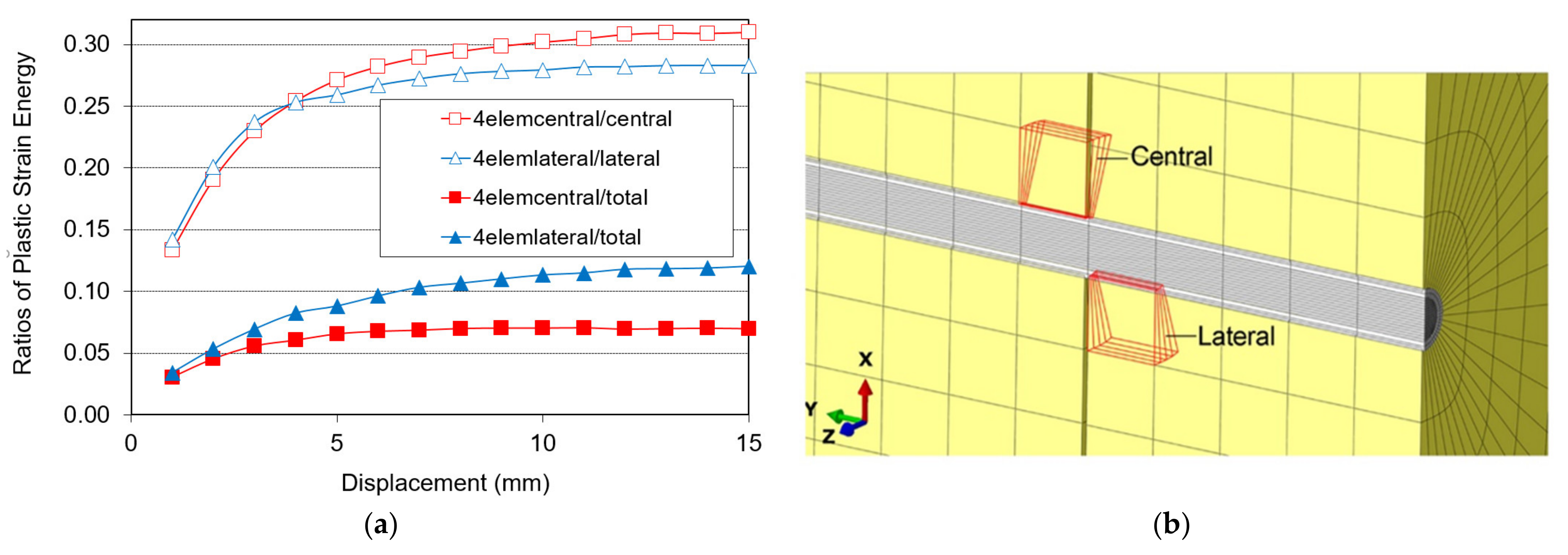
The four elements of each timber part highlighted in Figure 16b, located in the areas with the greatest concentration of energy as shown in Figure 14, were selected to quantify the concentration of energy. The ratios between the plastic strain energies of these elements and their respective timber parts, and between them and the whole joint were calculated. Their evolution is shown in Figure 16a. The study was restricted to the plastic strain energy because it is the most significant throughout the largest part of the displacement range.
Figure 16a shows how at 1 mm displacement, the plastic strain energy is relatively distributed, with the selected elements accumulating only 12% of its whole value. Then, when the displacement grows, the corners increase their plasticization, which generates the high slope of the curve between 1 and 7 mm displacement. From 7 mm displacement onwards, the slope of the curve decreases and the strain energy distribution ratio tends to remain almost constant.
At the end of the 15 mm displacement, only four elements of the central timber part accumulate 32% of all the plastic strain energy, and another four elements of the lateral part accumulate 28% of this energy. These percentages decrease to 12.5% and 7%, respectively, if the comparison is performed according to the plastic strain energy of the whole joint. This confirms the hypothesis supported by EC-5 [3] in its failure modes 3 and 4, where it proposes that these are highly plasticized areas.
Finally, an inverse tendency can be observed in the plastic strain energy of the four selected elements depending on whether it is considered with respect to the total joint or with respect to each of their respective parts. While with respect to the total joint, the plastic strain energy of the four elements in the lateral part is the most significant, with respect to their respective parts, the plastic strain energy in the four central elements has a higher ratio than the plastic strain energy in the four lateral elements. From this inverse tendency, it can be inferred that in the lateral timber part, in addition to the plastic strain energy, the elastic strain energy also has highly significant values and it contributes considerably to resisting the external load.
6. Conclusions
A finite element model was developed to simulate the mechanical behavior of dowel-type joints in timber structures using an expansive kit. Using a subroutine ad hoc model, it was designed to properly simulate the contact between the dowel and the surfaces of the holes in the timber parts, the compression stresses provoked by the expansive kit and the three-dimensional anisotropic elastoplastic behavior of the wood.
The accuracy of the model was checked against the results yielded by a set of experimental tests conducted following the appropriate regulations. It was found that the experimental results adequately fit the calculations performed using FEM and the subroutine. The breaks and deformations were located in the zones of maximum tension of both the wood and the steel dowel.
This model was used as the basis for a study to determine the advantages of using expansive kits. The results of the load vs. displacement curves indicate that, when the expansive kit is used, the load-carrying capacity of the joint increases by 7.2%. The model was also used to study the mechanical energy distribution between the different parts of the joint. A comparison between the two timber parts shows that both have the same energy when the displacement is low, but that the lateral part can have up to 80.4% more energy when the displacement is increased. With regard to the two steel parts, the sleeve and the rod, it can be observed that the sleeve has 57% more energy than the rod along the entire range of displacement. The use of an easily deformable steel as a sleeve combined with another that is also ductile but with a hardening surface treatment (in rod) means that the dowel is more resistant than if it were a single rod without an expansive kit. This combination helps to distribute stresses in the dowel.
Finally, it was verified that, whereas for small displacements the larger part of the mechanical energy corresponds to the elastic strains, when the displacement is increased, the mechanical energy due to the plastic strains acquires utmost importance. The rate by which the plastic strain energy exceeds the elastic strain energy at the final displacement of 15 mm depends on the part considered: 4.8 times higher in the lateral timber part, 3.8 times in the central timber part, 2.07 times in the sleeve and 1.85 in the rod. The major part of this energy appears to be concentrated in very small zones at the ends of the holes of the timber parts and in the hinges of the rod and sleeve, as proposed by EC-5.
Author Contributions
Conceptualization, J.G.F. and M.D.; methodology, J.G.F. and M.D.; software, J.G.F. and J.A.C.; validation, J.G.F., J.A.C. and M.D.; formal analysis, J.A.C. and A.V.; investigation, J.G.F., M.D., J.A.C., N.A. and A.V.; resources, A.V.; data curation, M.D. and N.A.; writing—original draft preparation, J.G.F. and N.A.; writing—review and editing, A.V., J.A.C. and N.A.; project administration, J.G.F. All authors have read and agreed to the published version of the manuscript.
Funding
This work was funded by the Spanish government, VI National Plan for Scientific Research, Development and Technological Innovation of the Ministry of Economy and Competitiveness, within the framework of research project BIA2012-36766.
Institutional Review Board Statement
Not applicable.
Informed Consent Statement
Not applicable.
Conflicts of Interest
The authors declare no conflict of interest.
References
- Kasal, B.; Pospisil, S.; Jirovský, I.; Heiduschke, A.; Drdacky, M.; Haller, P. Seismic performance of laminated timber frames with fiber-reinforced joints. Earthq. Eng. Struct. Dyn. 2004, 33, 633–646. [Google Scholar] [CrossRef]
- CEN/Technical Committee 124. Structural Timber—Determination of Characteristic Values of Mechanical Properties and Density EN 384:2016+A1:2018; European Committee for Standardization: Brussels, Belgium, 2018. [Google Scholar]
- CEN/Technical Committee 250. Eurocode 5: Design of Timber Structures—Part 1-1: General—Common Rules and Rules for Buildings EN 1995-1-1:2004/A2:2014; European Committee for Standardization: Brussels, Belgium, 2014. [Google Scholar]
- CEN/Technical Committee 124. Timber Structures—Glued Laminated Timber and Glued Solid Timber—Requirements EN 14080:2013; European Committee for Standardization: Brussels, Belgium, 2013. [Google Scholar]
- Milch, J.; Tippner, J.; Brabec, M.; Sebera, V.; Kunecký, J.; Kloiber, M.; Hasníková, H. Experimental testing and theoretical prediction of traditional dowel-type connections in tension parallel to grain. Eng. Struct. 2017, 152, 180–187. [Google Scholar] [CrossRef]
- El-Houjeyri, I.; Thi, V.-D.; Oudjene, M.; Khelifa, M.; Rogaume, Y.; Sotayo, A.; Guan, Z. Experimental investigations on adhesive free laminated oak timber beams and timber-to-timber joints assembled using thermo-mechanically compressed wood dowels. Constr. Build. Mater. 2019, 222, 288–299. [Google Scholar] [CrossRef]
- Iraola, B.; Cabrero, J.; Basterrechea-Arévalo, M.; Gracia, J. A geometrically defined stiffness contact for finite element models of wood joints. Eng. Struct. 2021, 235, 112062. [Google Scholar] [CrossRef]
- Tuhkanen, E.; Mölder, J.; Schickhofer, G. Influence of number of layers on embedment strength of dowel-type connections for glulam and cross-laminated timber. Eng. Struct. 2018, 176, 361–368. [Google Scholar] [CrossRef]
- Dourado, N.; da Silva, F.G.A.; de Moura, M. Fracture behavior of wood-steel dowel joints under quasi-static loading. Constr. Build. Mater. 2018, 176, 14–23. [Google Scholar] [CrossRef]
- Yurrita, M.; Cabrero, J.M.; Quenneville, P. Brittle failure in the parallel-to-grain direction of multiple shear softwood timber connections with slotted-in steel plates and dowel-type fasteners. Constr. Build. Mater. 2019, 216, 296–313. [Google Scholar] [CrossRef]
- Wei, P.; Wang, B.J.; Li, H.; Wang, L.; Peng, S.; Zhang, L. A comparative study of compression behaviors of cross-laminated timber and glued-laminated timber columns. Constr. Build. Mater. 2019, 222, 86–95. [Google Scholar] [CrossRef]
- Nie, Y.; Karimi-Nobandegani, A.; Valipour, H.R. Experimental behaviour and numerical modelling of timber-timber composite (TTC) joints. Constr. Build. Mater. 2021, 290, 123273. [Google Scholar] [CrossRef]
- Rad, A.R.; Burton, H.; Weinand, Y. Performance assessment of through-tenon timber joints under tension loads. Constr. Build. Mater. 2019, 207, 706–721. [Google Scholar] [CrossRef]
- Pavković, K.; Stepinac, M.; Rajčić, V. Brittle failure modes in reinforced and non-reinforced timber joint with large diameter fastener loaded parallel to grain. Eng. Struct. 2020, 222, 111104. [Google Scholar] [CrossRef]
- dos Santos, C.; Morais, J.; de Jesus, A.M. Mechanical behaviour of wood T-joints. Experimental and numerical investigation. Frat. Integrità Strutt. 2014, 31, 23–37. [Google Scholar] [CrossRef] [Green Version]
- Vassiliou, V.; Barboutis, I.; Kamperidou, V. Strength of corner and middle joints of upholstered furniture frames constructed with black locust and beech wood. Wood Res. 2016, 61, 495–504. [Google Scholar]
- Tang, L.; Yang, H.; Crocetti, R.; Liu, J.; Shi, B.; Gustafsson, P.J.; Liu, W. Experimental and numerical investigations on the hybrid dowel and bonding steel plate joints for timber structures. Constr. Build. Mater. 2020, 265, 120847. [Google Scholar] [CrossRef]
- Lacourt, P.A.; Crisafulli, F.J.; Mirasso, A.E. Finite element modelling of hysteresis, degradation and failure of dowel type timber joints. Eng. Struct. 2016, 123, 89–96. [Google Scholar] [CrossRef]
- Bouchard, R.; Salenikovich, A.; Frenette, C.; Bedard-Blanchet, G. Experimental investigation of joints with multiple glued-in rods in glued-laminated timber under axial tensile loading. Constr. Build. Mater. 2021, 293, 122614. [Google Scholar] [CrossRef]
- Toumpanaki, E.; Ramage, M.H. Glued-in CFRP and GFRP rods in block laminated timber subjected to monotonic and cyclic loading. Compos. Struct. 2021, 272, 114201. [Google Scholar] [CrossRef]
- Xu, B.-H.; Li, D.-F.; Zhao, Y.-H.; Bouchaïr, A. Load-carrying capacity of timber joints with multiple glued-in steel rods loaded parallel to grain. Eng. Struct. 2020, 225, 111302. [Google Scholar] [CrossRef]
- Masaeli, M.; Gilbert, B.; Karampour, H.; Underhill, I.; Lyu, C.; Gunalan, S. Scaling effect on the moment and shear responses of three types of beam-to-column connectors used in mass timber buildings. Eng. Struct. 2020, 208, 110329. [Google Scholar] [CrossRef]
- Wang, Y.; Geng, Y.; Ranzi, G.; Zhang, S. Time-dependent behaviour of expansive concrete-filled steel tubular columns. J. Constr. Steel Res. 2010, 67, 471–483. [Google Scholar] [CrossRef]
- Murakami, R.; Onoue, K.; Morimoto, K.; Hashimoto, R. Effects of expansive filler and headed rebar on the shortening of development length of mortar-filled joints. J. Build. Eng. 2021, 40, 102338. [Google Scholar] [CrossRef]
- Li, Y.-L.; Zhao, X.-L. Experimental study on stainless steel blind bolted T-stub to square hollow section connections. Thin Walled Struct. 2021, 167, 108259. [Google Scholar] [CrossRef]
- Seo, S.-Y.; Nam, B.-R.; Kim, S.-K. Tensile strength of the grout-filled head-splice-sleeve. Constr. Build. Mater. 2016, 124, 155–166. [Google Scholar] [CrossRef]
- Zheng, Y.; Guo, Z.; Guan, D.; Zhang, X. Parametric study on a novel grouted rolling pipe splice for precast concrete construction. Constr. Build. Mater. 2018, 166, 452–463. [Google Scholar] [CrossRef]
- Rodd, P.D.; Leijten, A.J.M. High-performance dowel-type joints for timber structures. Prog. Struct. Eng. Mater. 2003, 5, 77–89. [Google Scholar] [CrossRef]
- Gattesco, N. Experimental study on multiple-bolt steel-to-timber tension joints. Mater. Struct. 2004, 37, 129–138. [Google Scholar] [CrossRef]
- Meghlat, E.-M.; Oudjene, M.; Ait-Aider, H.; Batoz, J.-L. A new approach to model nailed and screwed timber joints using the finite element method. Constr. Build. Mater. 2013, 41, 263–269. [Google Scholar] [CrossRef]
- CEN/Technical Committee 175. Moisture Content of a Piece of Sawn Timber—Part 2: Estimation by Electrical Resistance Method EN 13183-2:2002/AC:2003; European Committee for Standardization: Brussels, Belgium, 2003. [Google Scholar]
- CEN/Technical Committee 250. Eurocode 3: Design of Steel Structures—Part 1-1: General Rules and Rules for Buildings EN 1993-1-1:2005/A1:2014; European Committee for Standardization: Brussels, Belgium, 2014. [Google Scholar]
- CEN/Technical Committee 459. Hot Rolled Products of Structural Steels—Part 2: Technical Delivery Conditions for Non-Alloy Structural Steels EN 10025-2:2019; European Committee for Standardization: Brussels, Belgium, 2019. [Google Scholar]
- Larsen, H.J.; Jensen, J.L. Influence of semi-rigidity of joints on the behaviour of timber structures. Prog. Struct. Eng. Mater. 2000, 2, 267–277. [Google Scholar] [CrossRef]
- van der Put, T.A. A continuum failure criterion applicable to wood. J. Wood Sci. 2009, 55, 315–322. [Google Scholar] [CrossRef] [Green Version]
- Sawata, K.; Yasumura, M. Estimation of yield and ultimate strengths of bolted timber joints by nonlinear analysis and yield theory. J. Wood Sci. 2003, 49, 383–391. [Google Scholar] [CrossRef]
- Fajdiga, G.; Rajh, D.; Nečemer, B.; Glodež, S.; Šraml, M. Experimental and numerical determination of the mechanical properties of spruce wood. Forests 2019, 10, 1140. [Google Scholar] [CrossRef] [Green Version]
- Fu, W.-L.; Guan, H.-Y.; Kei, S. Effects of moisture content and grain direction on the elastic properties of beech wood based on experiment and finite element method. Forests 2021, 12, 610. [Google Scholar] [CrossRef]
- Xu, B.-H.; Bouchair, A.; Taazount, M.; Racher, P. Numerical 3D finite element modelling and experimental tests of rounded dovetail connection. Eur. J. Environ. Civ. Eng. 2013, 17, 564–578. [Google Scholar] [CrossRef]
- Guan, Z.; Zhu, E. Finite element modelling of anisotropic elasto-plastic timber composite beams with openings. Eng. Struct. 2009, 31, 394–403. [Google Scholar] [CrossRef]
- Schoenmakers, J.; Jorissen, A. Failure mechanisms of dowel-type fastener connections perpendicular to grain. Eng. Struct. 2011, 33, 3054–3063. [Google Scholar] [CrossRef]
- Reiterer, A.; Stanzl-Tschegg, S.E. Compressive behaviour of softwood under uniaxial loading at different orientations to the grain. Mech. Mater. 2001, 33, 705–715. [Google Scholar] [CrossRef]
- Iraola, B.; Cabrero, J.M. An algorithm to model wood accounting for different tension and compression elastic and failure behaviors. Eng. Struct. 2016, 117, 332–343. [Google Scholar] [CrossRef]
- Kharouf, N.; McClure, G.; Smith, I. Elasto-plastic modeling of wood bolted connections. Comput. Struct. 2003, 81, 747–754. [Google Scholar] [CrossRef]
- de Borst, R.; Feenstra, P.H. Studies in anisotropic plasticity with reference to the Hill criterion. Int. J. Numer. Methods Eng. 1990, 29, 315–336. [Google Scholar] [CrossRef]
- Holmberg, S.; Persson, K.; Petersson, H. Nonlinear mechanical behaviour and analysis of wood and fibre materials. Comput. Struct. 1999, 72, 459–480. [Google Scholar] [CrossRef]
- Chen, D.J.; Han, W.F. Plasticity for Structural Engineers; J Ross Publishing: Plantation, FL, USA, 2007. [Google Scholar]
- CEN/Technical Committee 124. Timber Structures—Joints Made with Mechanical Fasteners—General Principles for the Determination of Strength and Deformation Characteristics EN 26891:1991; European Committee for Standardization: Brussels, Belgium, 1991. [Google Scholar]
- Dorn, M.; de Borst, K.; Eberhardsteiner, J. Experiments on dowel-type timber connections. Eng. Struct. 2013, 47, 67–80. [Google Scholar] [CrossRef] [Green Version]
- Schweigler, M.; Bader, T.K.; Hochreiner, G. Engineering modeling of semi-rigid joints with dowel-type fasteners for nonlinear analysis of timber structures. Eng. Struct. 2018, 171, 123–139. [Google Scholar] [CrossRef]
- Xu, B.-H.; Taazount, M.; Bouchair, A.; Racher, P. Numerical 3D finite element modelling and experimental tests for dowel-type timber joints. Constr. Build. Mater. 2009, 23, 3043–3052. [Google Scholar] [CrossRef]
- Simulia. Available online: https://www.3ds.com/products-services/simulia/products/abaqus/ (accessed on 22 August 2021).
- Sadd, M.H. Elasticity: Theory, Applications, and Numerics; Elsevier Inc.: Amsterdam, The Netherlands, 2009. [Google Scholar]
- Guan, Z.; Rodd, P. Hollow steel dowels—A new application in semi-rigid timber connections. Eng. Struct. 2001, 23, 110–119. [Google Scholar] [CrossRef]
Figure 1.
Geometry of the joint.

Figure 2.
Reception, manufacture, test samples, moisture measurement and conditioning the hole for dowel insertion and weight measurement.
Figure 2.
Reception, manufacture, test samples, moisture measurement and conditioning the hole for dowel insertion and weight measurement.

Figure 3.
Configuration of timber (unpolished, top view), showing some heterogeneities (marked by red squares) and its plane of symmetry.
Figure 3.
Configuration of timber (unpolished, top view), showing some heterogeneities (marked by red squares) and its plane of symmetry.

Figure 4.
Example of the internal area of timber. Appearance of polished wood (P. abies) used in this work: (top and bottom) several details (indicated by red squares and magnified above and below) of the wood and (central) wood cut by the plane of symmetry of Figure 3, mid-configuration section.
Figure 4.
Example of the internal area of timber. Appearance of polished wood (P. abies) used in this work: (top and bottom) several details (indicated by red squares and magnified above and below) of the wood and (central) wood cut by the plane of symmetry of Figure 3, mid-configuration section.

Figure 5.
Metallurgical characterization of the sleeve and rod.

Figure 6.
Expansion of the steel tube using steel spheres.

Figure 7.
Finite element model.

Figure 8.
Uniaxial mechanical behavior models used for: (a) steel and (b) timber.

Figure 9.
Flow chart of the subroutine developed for modeling the mechanical behavior of timber.

Figure 10.
Specimen in the test machine.

Figure 11.
Comparison of finite element and experimental results. (a) Load vs. displacement and (b) external work vs. displacement.
Figure 11.
Comparison of finite element and experimental results. (a) Load vs. displacement and (b) external work vs. displacement.

Figure 12.
Mechanical energy distribution and energy ratios between the different joint parts. (a) Energies (N.mm) and (b) ratios between energies.
Figure 12.
Mechanical energy distribution and energy ratios between the different joint parts. (a) Energies (N.mm) and (b) ratios between energies.

Figure 13.
Elastic and plastic mechanical energies in the different parts of the joint when using the expansive kit. (a) Energies (N·mm) and (b) ratios between plastic and elastic energies.
Figure 13.
Elastic and plastic mechanical energies in the different parts of the joint when using the expansive kit. (a) Energies (N·mm) and (b) ratios between plastic and elastic energies.

Figure 14.
Elastic and plastic strain energies SENER & SDV70 and PENER & SDV71, respectively, in the different parts of the joint.
Figure 14.
Elastic and plastic strain energies SENER & SDV70 and PENER & SDV71, respectively, in the different parts of the joint.

Figure 15.
Deformed central section of the joint after the test (left) and details of the sleeve failures (right).
Figure 15.
Deformed central section of the joint after the test (left) and details of the sleeve failures (right).

Figure 16.
Ratios of plastic strain energies vs. displacement (a) between the high plastic-deformed corner elements represented on the right (b) and the whole joint and each timber part.
Figure 16.
Ratios of plastic strain energies vs. displacement (a) between the high plastic-deformed corner elements represented on the right (b) and the whole joint and each timber part.


Table 1.
Mean properties of the timber used, of strength class GL24h (P. abies).
| Properties | Symbol | Value |
|---|---|---|
| Bending strength (N/mm2) | fm,g | 29.8 |
| Tensile strength parallel to grain (N/mm2) | ft,0,g | 23.8 |
| Tensile strength perpendicular to grain (N/mm2) | ft,90,g | 0.6 |
| Compressive strength parallel to grain (N/mm2) | fc,0,g | 29.8 |
| Compressive strength perpendicular to grain (N/mm2) | fc,90,g | 3.1 |
| Shear strength parallel to grain (N/mm2) | fv,g | 4.3 |
| Modulus of elasticity parallel to grain (N/mm2) | E0,g | 11,500 |
| Modulus of elasticity perpendicular to grain (N/mm2) | E90,g | 300 |
| Poisson’s ratio LT | νLT | 0.41 |
| Poisson’s ratio LR | νLR | 0.41 |
| Poisson’s ratio RT | νRT | 0.51 |
| Shear modulus (N/mm2) | Gg | 650 |
| Density (kg/mm3) | ρg | 420 |
Table 2.
Frictional dissipation and distribution of the internal energy (in percentage) between the different parts of the joint.
Table 2.
Frictional dissipation and distribution of the internal energy (in percentage) between the different parts of the joint.
| Internal strain energy (ALLIE) | Lateral | 44% |
| Central | 26% | |
| Sleeve | 11% | |
| Rod | 7% | |
| Block | ~0 | |
| Frictional dissipation (ALLFD) | 12% |
Publisher’s Note: MDPI stays neutral with regard to jurisdictional claims in published maps and institutional affiliations. |
© 2021 by the authors. Licensee MDPI, Basel, Switzerland. This article is an open access article distributed under the terms and conditions of the Creative Commons Attribution (CC BY) license (https://creativecommons.org/licenses/by/4.0/).
Share and Cite
MDPI and ACS Style
Fueyo, J.G.; Cabezas, J.A.; Domínguez, M.; Antón, N.; Villarino, A. Energy Distribution in Dowel-Type Joints in Timber Structures When Using Expansive Kits. Forests 2021, 12, 1200. https://doi.org/10.3390/f12091200
AMA Style
Fueyo JG, Cabezas JA, Domínguez M, Antón N, Villarino A. Energy Distribution in Dowel-Type Joints in Timber Structures When Using Expansive Kits. Forests. 2021; 12(9):1200. https://doi.org/10.3390/f12091200
Chicago/Turabian StyleFueyo, Jose G., Jose A. Cabezas, Manuel Domínguez, Natividad Antón, and Alberto Villarino. 2021. "Energy Distribution in Dowel-Type Joints in Timber Structures When Using Expansive Kits" Forests 12, no. 9: 1200. https://doi.org/10.3390/f12091200
Note that from the first issue of 2016, this journal uses article numbers instead of page numbers. See further details here.