1. Introduction
Electrical machines are part of a wide variety of applications for use from domestic and industrial to remote research applications on land, air, water, and finally in space, each one with its own characteristics and specific protections [
1]. Modern systems are complex, and new approaches in electric motor control are demanded, having high-precision requirements of speed and position under variable load torque. Consequently, it is necessary to develop new proposals for control and protection of electric motors [
2,
3].
Although direct current (DC) machines have been widely studied, there are still many possibilities for their use as motors and generators [
4]. An open research topic about DC shunt motor control is addressed to achieve a highly efficient and robust performance by using measurements of the output signal to be controlled. In fact, it is widely known that energy efficiency is related to operation costs. Certainly, this problem is quite challenging when some detailed mathematical model of the nonlinear dynamic system exposed to time-varying disturbances is not available. Moreover, in several practical engineering applications, the exact values of the system parameters are also unavailable. Thus, control policies for electric motors installed in industrial plants should be performed by using measurements of the output signal and a single voltage input.
On the other hand, speed reference trajectory tracking controllers for motors based on efficient motion planning could demand measurements of several state variables, increasing control implementation costs. Therefore, motors must demonstrate a satisfactory performance in a wide range of operating conditions and adaptability characteristics to face the changing demands of the load torque and environmental conditions. For instance, DC motors are used in many areas such as mobile robotics, industrial robotic arms, electric vehicles, elevators, cranes and drills, which demand variable operating conditions.
Diverse control approaches have been reported in the literature for electric motors. Robustness and an acceptable transient response for the practical closed-loop system are some relevant main objectives to be considered in the controller synthesis. However, those control performance requirements are still an open and challenging research problem for scenarios where a detailed mathematical model and accurate values of the system parameters are unavailable, and a minimal (optimal) number of sensors and actuators is preferred for reduction of implementation costs. Moreover, a nonlinear dynamic system could be subjected to unknown endogenous and exogenous disturbances affecting the performance indicators specified for the system response. There are several controllers based on sliding modes [
2], predictive control [
4], conventional proportional-integral-derivative (PID) techniques [
5,
6,
7,
8], robust control [
9], neural networks [
1,
10], and fuzzy logic [
11]. Some relevant aspects of these contributions are described in the next paragraphs. Nevertheless, most of them require full or partial information of the mathematical model and motor parameters, limiting their application because controllers are depending on the availability of these values [
4,
10,
11]. Motors as electric actuators are employed in many practical engineering systems; therefore, obtaining this information is an additional task, and it is possible that the controller performance could be degraded. Moreover, some of them have a high computational cost which could restrict their operation for real time applications [
10]. For instance, radial basis function neural networks are formed by three layers (input-hidden-output), and the number of neurons in each layer is also an important issue for correct performance. This fact increases the number of calculations to obtain a desired performance; furthermore, an offline learning rule may be necessary due to the amount of system data required for the training process. These aspects restrict the training stage and include a wider range of operating conditions. For B-spline neural networks, only a layer is required and an on-line learning rule is used. The number of computational calculations is based on basic operations (sum, subtraction, multiplication) with a smaller number of layers and neurons. In addition, only the evaluation of two basis functions is necessary. Therefore, B-spline neural networks qualify as an adequate option to be applied in the synthesis of some adaptive and robust tracking control scheme with low computational costs.
Speed control of a DC motor with known input delay and unknown disturbances is presented in [
4]. Controllers based on a predictive technique are used to obtain a satisfactory performance in the presence of disturbances. A simplified transfer function of the DC motor with a retarded input is employed for design purposes. Experimental and simulation studies are included to show the introduced controller performance. In [
5], a fractional-order technique is integrated into PI/PID linear controllers as a method to enhance their performance. The controller behavior is shown by a DC motor system where its dynamics are described by a conventional first-order model plus dead time. Here, simulation and experimental results are also presented. Ref. [
9] combines robust design with robust control and presents results of the coupling between them. An objective function based on these two concepts in the presence of uncertainty is proposed. Moreover, simulation results are exhibited for design performance evaluation. In particular, the analysis and design of DC motor controllers is emphasized for so-called direct current permanent magnet, or separate excitation, reaching simple linear models, and justifying its performance against certain operating conditions [
4,
8,
10,
11]. Its operation is guaranteed around some equilibrium point and is also highly dependent on the knowledge of the motor parameters. In this configuration, the inrush current is only limited by the armature resistance, which is relatively high for small motors and, thus, there are no large current problems. However, for motors of several electric powers, the armature resistance is small, and then an excessively high armature current is present in a starter condition at rated voltage [
12]. Therefore, a starter resistor is connected in series to the armature winding, causing losses and the need to include and turn off starting resistors.
The use of adaptive control algorithms offers an attractive alternative for speed tracking of DC motors [
10,
11,
13,
14]. A direct adaptive fuzzy logic controller is exposed in [
11]; it is estimated from two levels—one uses a Mamdani fuzzy controller and the other is an inverse model based on a Takagi–Sugeno method. Experimental results validate the controller behavior. In [
10], an adaptive neural controller for the tracking problem of a DC motor is presented. The neural networks are used to estimate the unknown functions included in the systems. The state variables of the DC motor are required to be constrained in the compact set in controller design procedure. Simulation results validate the stability analysis of the design.
The DC shunt motor configuration discussed in this paper considers its nonlinear dynamics, which makes the design of some robust speed control scheme a non-simple task [
12]. In this paper, robustness is considered against parametric uncertainty and disturbances due to variable load torque. Thus, conventional linear speed controllers could not be sufficient to suitably regulate some motor for a wide range of possible uncertain operating conditions. This motor configuration intends that the change in the mechanical load torque from zero to full value induces a minimal impact on the rotor speed, including sudden changes over time. Since DC shunt motors have wide applicability, it is required to expand the existing studies with the inclusion of adaptive control techniques to cover highly demanding conditions, to which the motor could be exposed. Hence, the efficient and robust control of electric motors using a minimum number of sensors is a challenging, relevant and pertinent research topic, and its solutions admit a wide variety of real applications in the development of engineering products and systems.
On the other hand, artificial neural networks (ANN) are able to model and control nonlinear and non-stationary systems on-line. The nature of this technique makes the controller robust, adaptive and optimal for use in independent or hybrid configurations with existing techniques. These features offer an important option to practicing engineers facing uncertain changes in physical systems and high demands of connected loads. ANN are particularly attractive for controlling electric motors. At the same time, they consider the complexity of the physical system and provide a realistic control with less computational time for an efficient and robust control in a wide operating range. In this regard, B-spline neural networks (BSNN) are a particular class of neural networks that have exhibited important results in various practical physical systems [
15,
16,
17,
18,
19,
20]. This paper presents the design and performance assessment of an adaptive tracking control approach based on B-spline neural networks with the capabilities required for real-time applications of DC shunt motors, without requiring a detailed mathematical model and values of the parameters of the nonlinear dynamic system. The results exhibit its ability to adapt and face changes in motor speed conditions and variable load torque disturbance inputs. The proposed controller shows that only a previous off-line training for some operating conditions is required and based on weights updating together with the base functions shape, it adapts to changes in the original design without losing its high performance. The result is an adaptive and robust control scheme that enhances the motor operation even in operating conditions different to where the design was done. In the present study, a high tracking performance refers to achieving small deviations from the speed reference trajectory planned for the closed-loop motor dynamics, in spite of endogenous and exogenous disturbances due to load torque and system parameters which are assumed to be unknown. Moreover, the proposed tracking control scheme only requires measurements of the speed output signal. Real-time measurements or estimations of acceleration, current and disturbance signals are then avoided. Experimental results confirm the effectiveness of the proposed control approach for highly demanding motor operation conditions subjected to variable speed reference trajectories and completely unknown load torque. Therefore, laboratory experimental tests on a DC shunt motor prove the viability of the proposed adaptive output feedback trajectory tracking control approach.
2. DC Shunt Motor Model
There are various configurations of DC motors, where one in particular provides important operating characteristics where the rotor speed does not change appreciably as the load torque varies from zero to its nominal value [
12].
Figure 1 shows a connection diagram of the motor under the present study.
In this figure, we can distinguish in the field winding the following elements: is the field winding inductance, is the field resistance, is an external variable resistance, is the field current, and is the field voltage. In the armature winding, the elements available are: is the armature winding inductance, is the armature resistance, is the armature current, and is the armature voltage. is the mutual winding inductance and ω is the rotor speed.
We can see that the voltage source supplies both the field winding and the armature winding; therefore, the total current
is the sum of the two circulating currents
. Considering the voltage-current relation for resistive and inductive elements, and grouping the field resistive elements in
, the DC motor model is obtained as
The relationship among electrical and mechanical systems is determined by
where
J is the moment of inertia of the rotor,
b is the viscous damping coefficient, and
is the load torque. Here, the electric torque is
. The mathematical model exhibits a coupled nonlinear dynamic system. Therefore, conventional linear controllers can only guarantee a satisfactory operation around a certain equilibrium point. From the mathematical model, the equilibrium points of the system can be determined as
where
. It can be seen that the equilibrium points depend on the voltage applied on terminals, the load torque and motor parameters. Therefore, the motor has multiple equilibrium points depending precisely on the desired operating condition.
3. Control Design Approaches Based on the Mathematical Model
In this section, two conventional control design methodologies based on the use of some mathematical models of the dynamic system are described in order to show the main differences of the robust adaptive control approach proposed in this paper. The first control method is based on a linear mathematical model. Hence, the linear controller is only valid around some specific equilibrium operation point. The second control method is based on sliding modes that consider a mathematical model of the system that is available. Moreover, some values of the system parameters are required for controller implementation. In spite of good performance indicators of both control design methods, the use of some mathematical model and the knowledge of system parameters could be a relevant limitation for the implementation of several nonlinear control techniques in real shunt electric motors.
Therefore, the proposed adaptive control approach represents a very good alternative choice for speed reference trajectory tracking tasks planned for DC shunt electric motors subjected to disturbances due to system uncertainty and completely unknown variable load torque. Thus, the use of a detailed nonlinear mathematical model of the dynamic system, a priori knowledge of exact values of machine parameters and real-time measurements or estimation of acceleration, current and load torque become unnecessary in our robust control approach based on B-spline neural networks.
3.1. Linear Controller Design
The linear model representation can be obtained by small signal analysis around an equilibrium point, defining
,
,
, the linearized form of Equations (
1)–(
3) are given by
where
and
are the control and torque inputs, respectively, of the DC motor, and
where
,
and
are related to the nonlinear model described by Equations (
1)–(
3).
The above partial derivatives are evaluated at the equilibrium point about which the small perturbation is being analyzed. Around this operating condition, some linear control scheme can be easily designed from basic control fundamentals. Therefore, satisfactory velocity regulation can be guaranteed in a small neighborhood operation where the system dynamics can be conveniently approximated by the linear mathematical model.
Notice that eigenvalues of the linearized system model depend on the motor parameters and operating conditions. Thus, system poles are moving in the complex plane depending on the operating conditions of the machine. Hence, the system damping and natural frequency could be changed in several manners. There are different ways for tuning a linear controller. From this representation, it is clear that controller gains and time constants are dependent on motor operating conditions. In any case, an acceptable and stable controller performance can only be guaranteed around a specific equilibrium point.
3.2. Super-Twisting Sliding Mode Control Design
In this subsection, a modern control approach based on sliding modes is described. In fact, the sliding mode control methodology is quite known due to the controller robustness with respect to parametric uncertainty and exogenous disturbances. Interested readers are referred to the excellent book about sliding mode control [
21].
First of all, the speed tracking error variable is defined as:
, where
is the reference shaft speed. To design a controller, we define the state variables as:
and
. A control algorithm for the DC shunt motor based on second order sliding modes can be proposed as follows:
with
,
and
, where
is the controller gain. Note that the sliding surface
s also demands measurements of the acceleration signal.
Differentiating
s with respect to time and considering Equations (
9) and (
10), the dynamics of the sliding variable is given by
where
,
, and
ϕ is defined as
where
,
are constants, depending on the uncertain motor parameters. The system motion in sliding mode is independent of parameters
,
c and disturbances in
ϕ. The Lyapunov function to determine the stability of the proposed system is given by [
21]
The stability proof consists of a time derivative of the Lyapunov function and second derivative of
s to make an evaluation of the uncertainty behavior, on the basis of which can be shown that the uncertain state trajectory in the plane twists around the origin converging to it in finite time as in [
22].
The super-twisting sliding mode controller implementation is done by simultaneously solving Equations (
9)–(
13) in each sample time and the actual rotor speed must be available. To improve the input voltage, a low pass filter can be included in the control signal, and another alternative is by means of the concept of equivalent control. In this case, all motor parameters are required.
4. Proposed Adaptive B-Spline Controller Design
Considering the nonlinear nature of DC motors described in section two and a linear controller, a problem arises with the regulation of the interest variables. If it is possible, the control law must get a driver that is robust, even tracking speed trajectories over time. A number of neural networks-based structures have been developed to improve the system robustness. B-spline has been used for solving a great deal of mathematical and practical problems, demonstrating fast and precise results [
18,
19,
20]. In that sense, in this work, an adaptive controller based on B-spline neural networks is proposed. Its design consists of two stages: first in defining the structure and characteristics of the inputs and the training rule; the second part is an on-line learning where the ANN by itself can determine changes in the reference signal, load torque and motor parameters.
There are several examples where the conventional techniques are changed or improved with adaptive algorithms in different applications fields. In [
20], neural networks training is presented with an on-line procedure for power electronic applications.
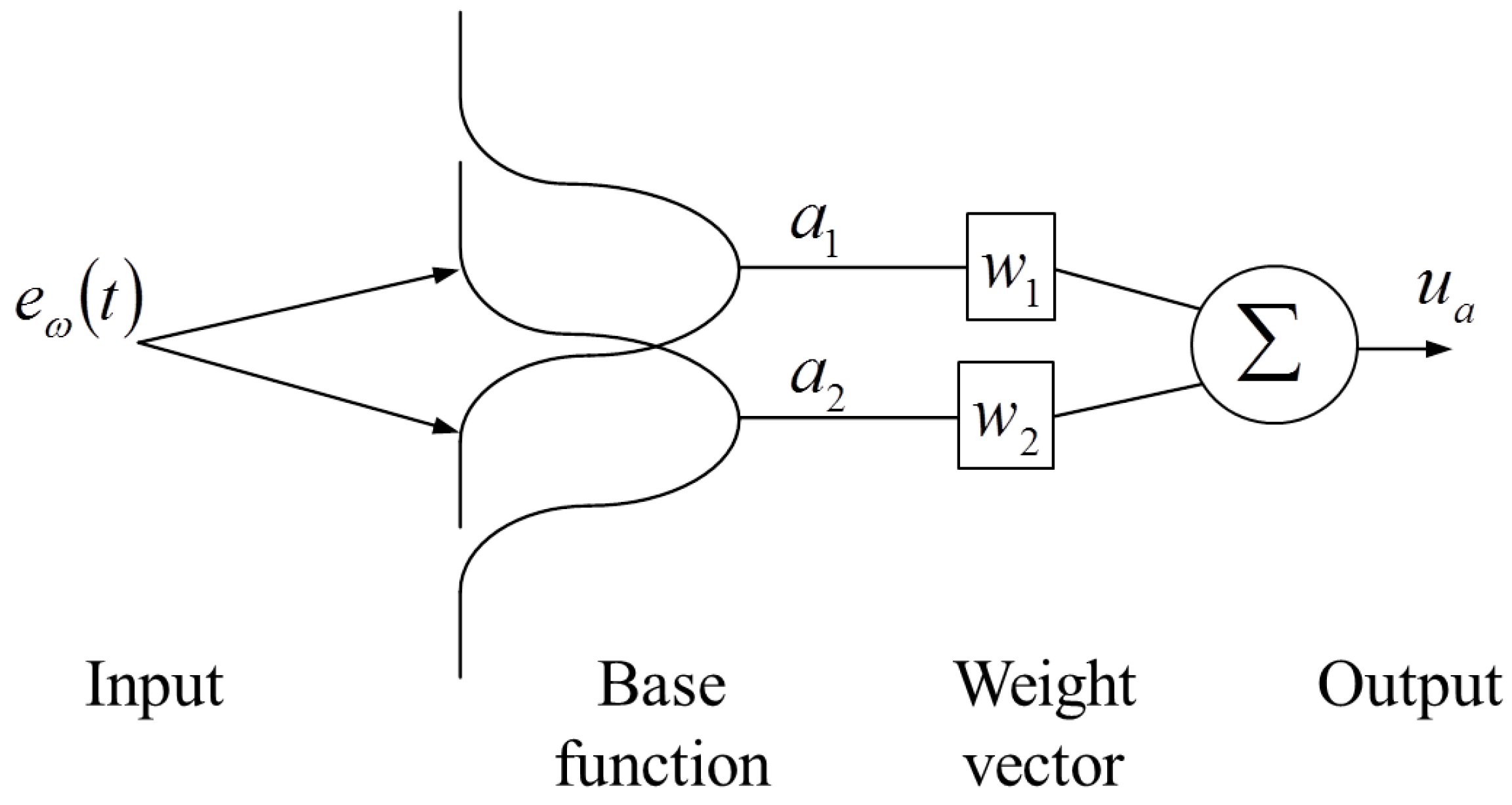
Figure 2 presents the B-spline neural network structure where only a layer with two basis functions is necessary; this is the basic concept to understand the adaptive scheme requirements. This structure consists of an input space, a layer formed with basis functions output and a weight vector and the BSNN output. Some parameters have to be specified, such as inputs, the number and shape of basis functions and the learning rate; however, once the BSNN is specified, it achieves a good performance over wide range of operating conditions. We defined these features in an off-line stage, where the performance is verified by collected data of the DC shunt motor. The adaptive controller has the same form that is showed in
Figure 2: (1) an input (error between actual and reference speed); (2) two basis functions of three orders that have the same form that is exhibited in
Figure 2, and it is considered that the input signal is normalized; (3) two weights that are updating each sampling time; and (4) the output that is the sum of two elements: the product between basis function output and weights.
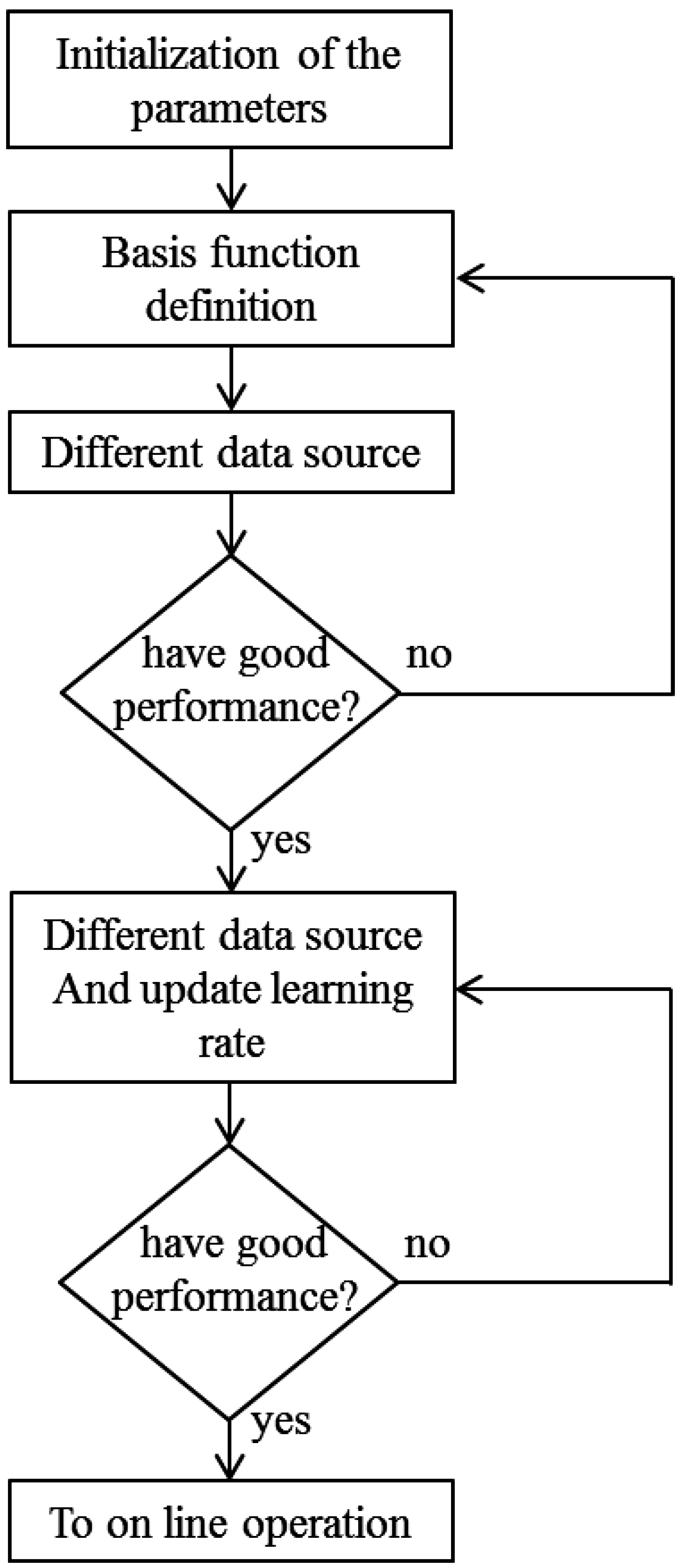
Figure 3 depicts the B-spline neural network training procedure in the off-line stage; here, the main elements of this structure are defined by some experiments based on the input–output (voltage-speed) data of the DC shunt motor. In the initialization step, a layer formed with two basis functions is defined as shown in
Figure 2. This configuration is proposed due to the presence of a single error signal, and good control performance criteria obtained in previous works [
15,
16,
17]. The shape of these basis functions permits a soft neural network output response, and different shapes are previously analyzed with superior orders, but the performance is similar with the restriction that a greater number of calculations is required. Finally, the weights are the same number of basis functions and the learning rule is the same for all cases. Based on this point, it is necessary to set a learning rate, and, for experimental purposes, a low magnitude is used: 1 × 10
. Later, it could be adjusted more precisely (greater or smaller) in such a way that the neural network response will be faster but the learning rule will remain stable. These experiments are developed based on input–output system data. In this study, the operation conditions used for off-line neural network training are showed in
Table 1. The first loop in the off-line training is exceeded if the learning rule is stable and the neural network output is between some expected values. For this motor, the input voltage inside the range of 0 to 110 V. If this is true, it is considered that the B-spline neural network has a good performance. In this stage, the number of inputs, learning rate, basis function number and basis function shape could be modified if it is necessary.
The second loop in the off-line training stage,
Figure 3, consists of subjecting the motor operation with the inclusion of the adaptive controller to different operation conditions until the closed loop response reaches the best transient evolution (settling time and overshoot). Here, the learning rate is the main parameter that must be adjusted because we are considering that the learning rule is stable. Good performance is attained when the closed loop response satisfies the control objectives. In on-line operation, a similar performance is expected where continuous learning of new operational and/or parametric variation of the motor is presented, which is demonstrated in this paper.
For this work, we have chosen only the rotor speed deviation as a BSNN input, which allows us to obtain a satisfactory control signal. Three testing configurations were analyzed for the basis function definition: (a) two multivariables with three and four orders; (b) multivariables with two and three orders and; and (c) monovariables with three orders. Each configuration has a different performance and the number of operations depends on the type and order of the basis function. This ANN structure has been explored in other dynamic systems showing a good performance [
15,
16,
17]. The data set used in this designation is presented in
Table 1. This was selected because it is a representative set of an input–output relationship of a typical DC motor operation.
Among the objectives of the proposed controller, we are looking to have robust but simple design features and implementation on an experimental level. Laboratory results demonstrate these aspects. In this work, the diagram in
Figure 2 defines the proposed neural controller and the output is defined by [
18]
where
and
are the
i-th weighting factor and the
i-th basis function output, respectively;
p is the number of weights of the neural network structure—for this case only two, hence
p = 2. The base function output changes with a nonlinear relationship of the input values, defined by the base function shape. For the proposed controller, two monovariable functions of third order are used [
15,
18]. The weight vector is updated by an instantaneous learning rule, defined by [
18]
where
η is the learning rate and
is the error between the desired and actual rotor speed. The update of the weights depends on the base functions output and the learning rule; therefore, the neural network performance is not conditional to the reference type (constant or variable) or to the actual operating conditions. With respect to the learning rate, it takes one point within the interval [1 × 10
,1.0] as an initial value for stability purposes. This value was adjusted by some test configurations considering a different data set. If
η is set close to 0, the training becomes slow. On the contrary, if this value is large, oscillations may occur. In this application, it has been settled at 1 × 10
.
There are some applications of adaptive controllers based on B-spline neural networks where how to define the base functions, neural network structure and a training rule are explained [
15,
16,
17,
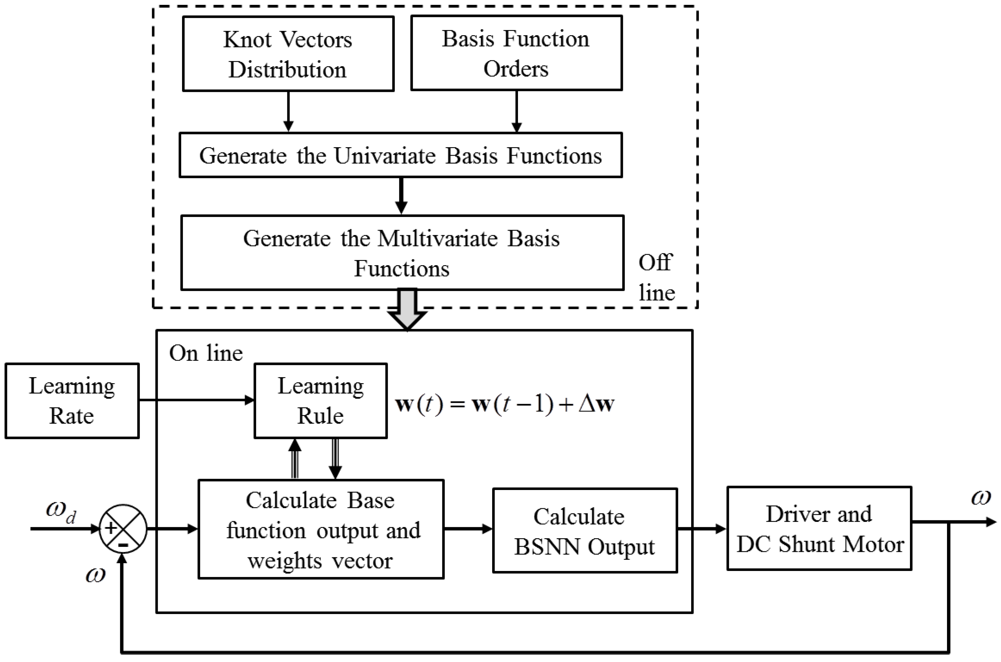
18]. A clearly simple structure facilitates the form of implementation and adaptation to different systems; in addition, the number of neurons, structure and shape of base functions have similarity in all these cases; therefore, the same structure can be extended for systems of different characteristics. It is important to note that, for implementation of these controllers, prior knowledge of the operation and control system analysis is required. Finally, this particular BSNN structure makes them a very attractive structure that can be exploited in hybrid with other control strategies that can be linear, robust or adaptive configurations. The block diagram of the control system is presented in
Figure 4. The adaptive controller has a continuous learning about DC motor operation. Equations (
15) and (
16) are implemented in a digital system to obtain the laboratory results.
5. Experimental Assessment of the DC Shunt Motor Control Scheme
In order to evaluate the effectiveness and efficiency of the proposed speed control scheme, several laboratory tests were performed for the controlled DC motor arrangement described in
Figure 1, under different unknown disturbance inputs. The parameters used for the off-line training are presented in
Table 2, which represent approximate values of the physical system. It is shown that the proposed approach with an initial off-line training controller for reference tracking is sufficient to face the change on the motor and the operation change.
For simplicity, the load torque in the simulation study (off-line training) is considered to be proportional to the velocity as follows
where the constant
B is calculated by a trial and error procedure, considering current and voltage signals measured in laboratory tests in a steady state with different load values.
5.1. Description of the Test Platform
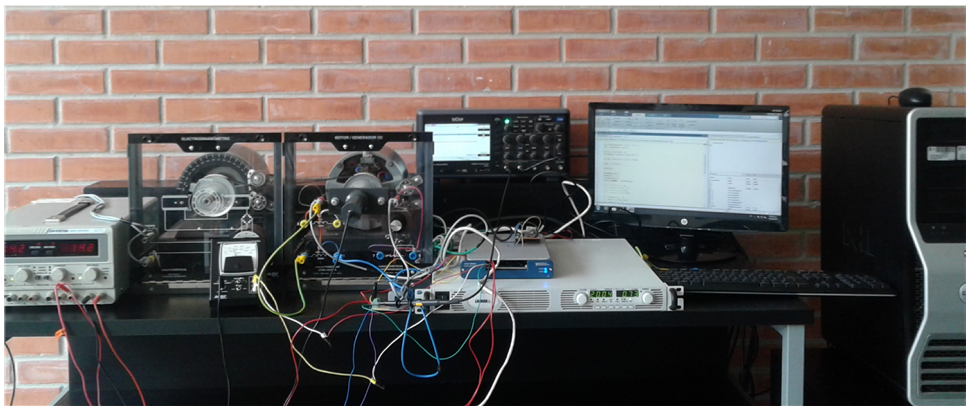
Some experiments were designed to recognize the performance of the proposed adaptive control scheme. The DC shunt motor was driven by a programmable DC power supply with TOSHIBA 2SK2611 (Hamamatsucho, Tokyo, Japan) MOSFET modules at a switching frequency of 3 MHz, including a dead time of 200 ns, formed by rise, turn-on, fall, and turn-off times. The MOSFET driver used was the Texas Instruments UCC27528-Q1 (Dallas, TX, USA). The machine is mechanically coupled to an electrodynamometer (squirrel-cage motor) loaded by a DC excited stator (0–100 Ω). Field and armature currents are measured with two hall effect sensors, which are converted through a 16 bits A/D converter. The rotor speed is measured with a permanent magnet tacho-generator.
The experimental laboratory test bed control equipment is based on a TM4C123GH6PMI microcontroller (Texas Instruments), a personal computer, and a multifunction data acquisition board with ±10 V analog input channels of 1 MS/s and 16 bits of resolution and; ±10 V output channels of 2.86 MS/s, and 16 bits of resolution (see
Figure 5). The microcontroller and the board are employed to implement the proposed control algorithm and generate the logic driving signals. It is connected to an Intel Xenon CPU to 2.90 GHz with 12.0 GB RAM memory. The development software operates under Matlab/Simulink environment (2015a, Boston, MA, USA).
5.2. Measurement Variables in the Laboratory Test Motor
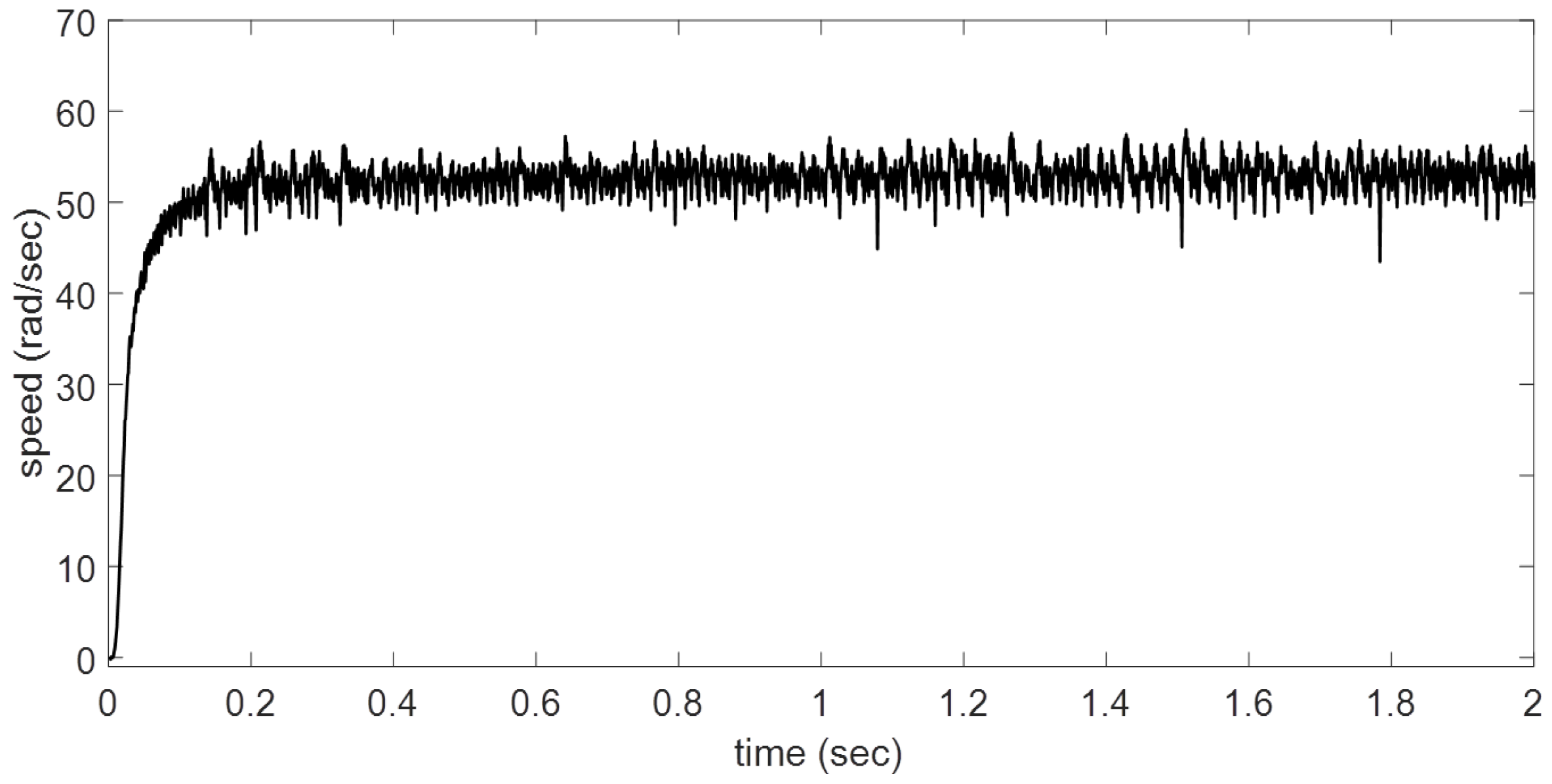
The DC motor was exposed to four scenarios. In the first case a, all variables are zero after the speed reference is changed to 50 rad/s, considering a constant load torque. An electrodynamometer is connected to the motor shaft, which is used as load.
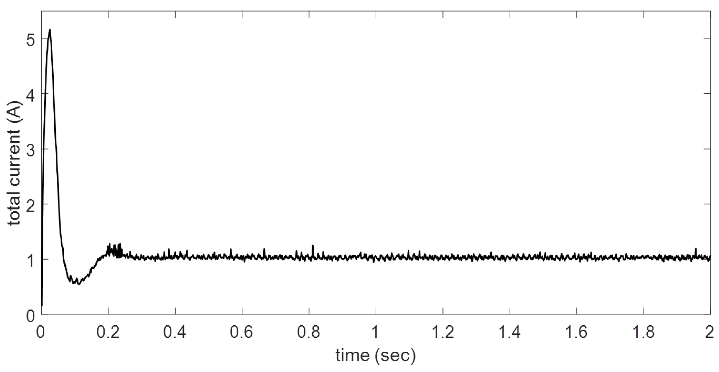
The rotor speed and total current are shown in
Figure 6 and
Figure 7. The DC motor performance is in accordance with the design stage. The proposed BSNN controller is able to regulate the speed with a desired behavior without the knowledge of the system model and parameters. It is enough to have collected data from the physical system—in this case, input voltage a rotor speed or an approximate mathematical model to know some possible characteristics about interest variables in transient and steady state conditions.
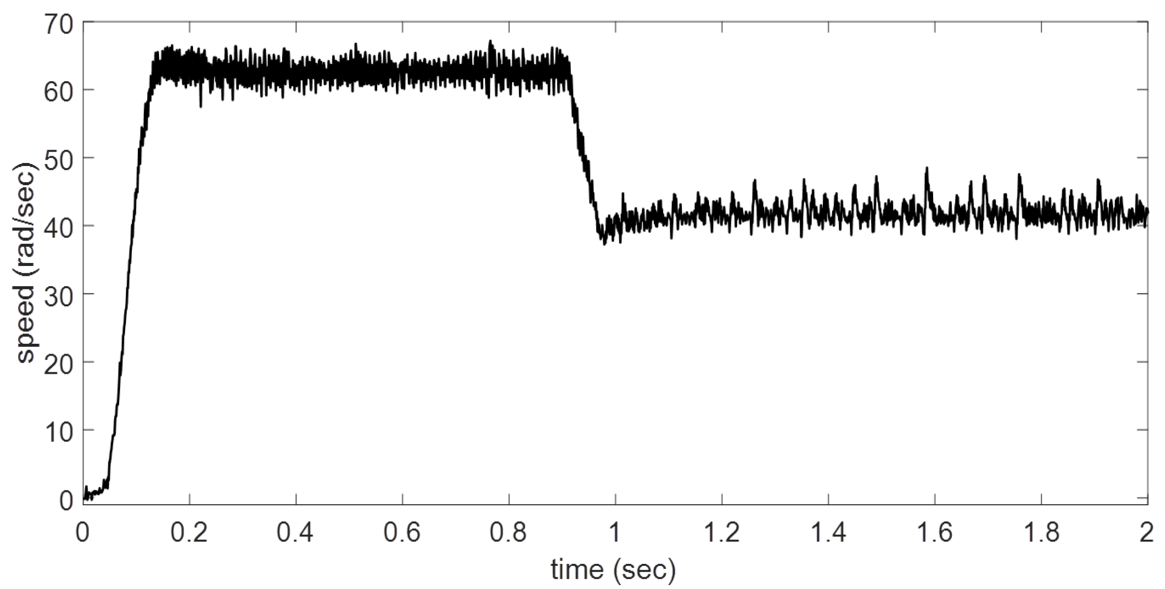
The second case
b exhibits the reference tracking performance when the reference speed is changed from 0 to 63 rad/s and then to 42 rad/s (
Figure 8). The controller has a good evolution when the speed reference is diminished, in the same sense to reference increases. It is clear that the main overshoot is presented when the rotor speed changes from 63 to 42 rad/s with a constant load torque. The oscillations are eliminated faster with the proposed adaptive controller. The settling time is less than to 0.2 s for BSNN in both cases.
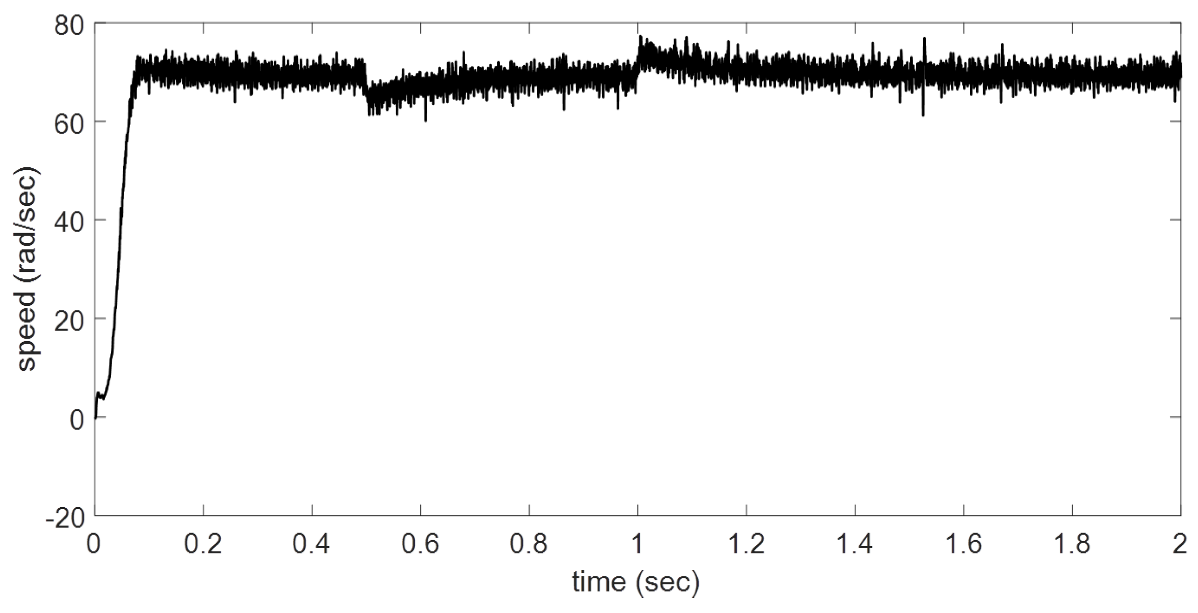
Case
c includes a load torque with different values. First, the rotor speed achieves 70 rad/s; after that, at
t = 0.5 s, an electrodynamometer is included. In the last part at
t = 1 s, the load torque is disconnected (
Figure 9). The field current exemplifies the DC shunt motor performance, and all variables attain a behavior with similar features with all presented study cases. The BSNN can be updated to a new operating condition, improving its performance. In this case, the change in load torque has a minimal effect in rotor velocity.
Figure 10 depicts the field current performance when the system is faced with different disturbances.
The adaptability of the proposed controller has been presented by prior off-line design. A mathematical model with approximate motor parameters was used, and the design was performed by data collected by the model and laboratory test system. The performance of the proposed adaptive controller is evaluated by results obtained experimentally. This behavior validates the initial design methodology.
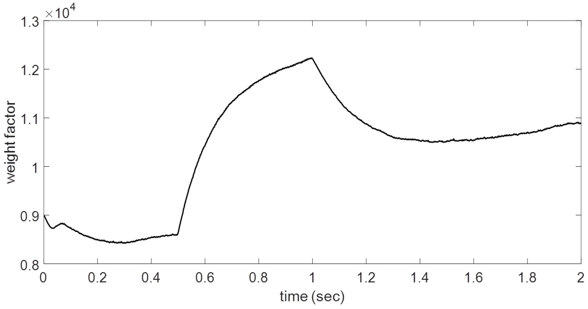
The adaptive neural controller performance is guaranteed by two main features: the off-line training and the continuous learning in each sample time, and is reflected in the weight factor. This evolution is exhibited in
Figure 11 by one of the two weights of the B-spline neural network structure, and the main change is presented when some of the motor system configuration changes, and obviously, in steady state condition, its value is maintained constant because the error magnitude is near to zero. The learning rate is related to the velocity response of the weight factors; in this case, it has an initial value equal to 8952 obtained in the previous training. This performance is expected while the continuous learning rule (
16) is operating.
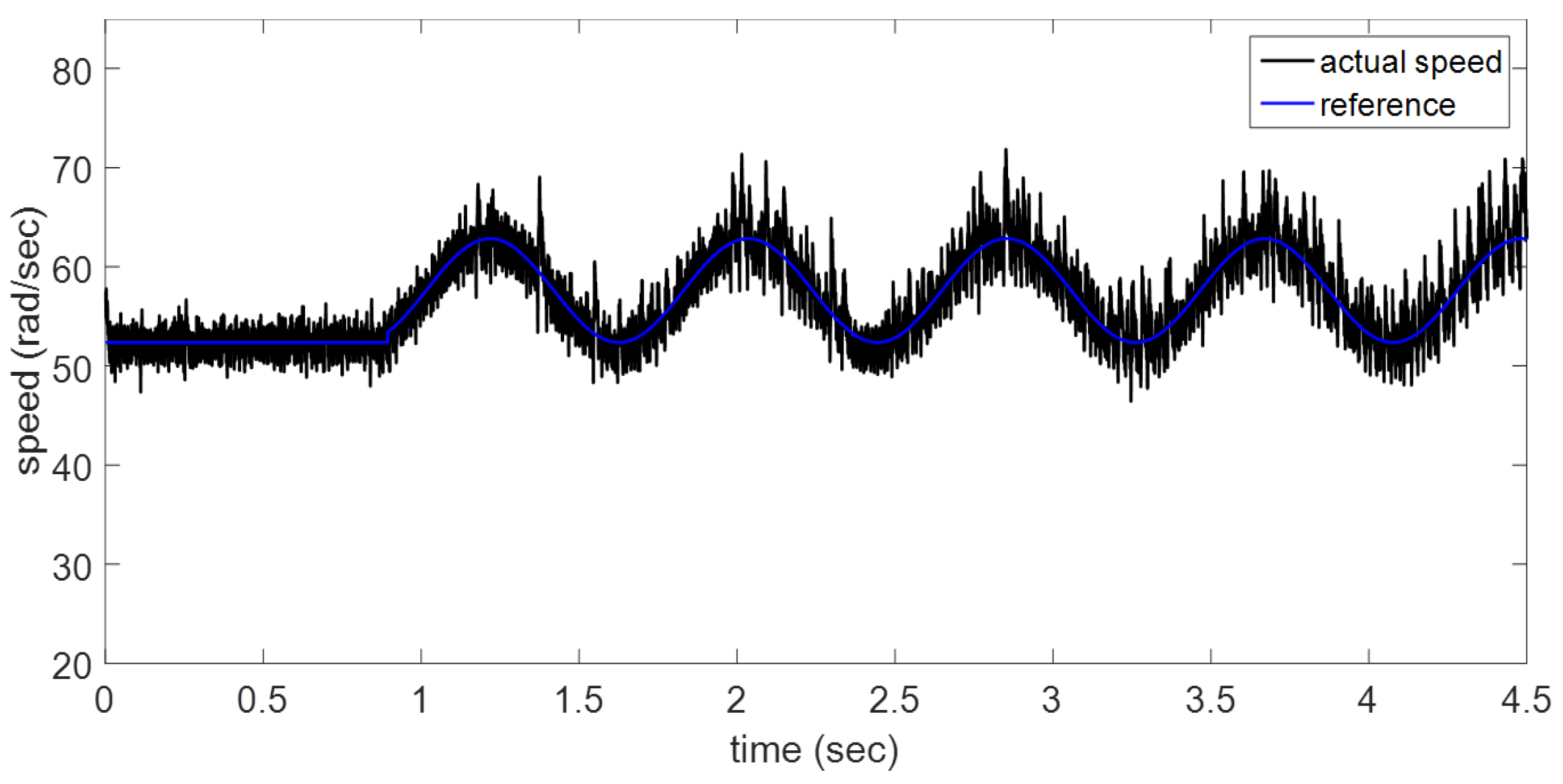
In case
d, a trajectory tracking performance is presented. The first 0.8 s a steady state rotor speed is exhibited, after the reference speed is modified as a time function for trajectory tracking evaluation. The proposed adaptive controller achieves the reference speed requirements (
Figure 12). This kind of performance is one of the main advantages of the adaptive controller when a design structure has been conditioned.
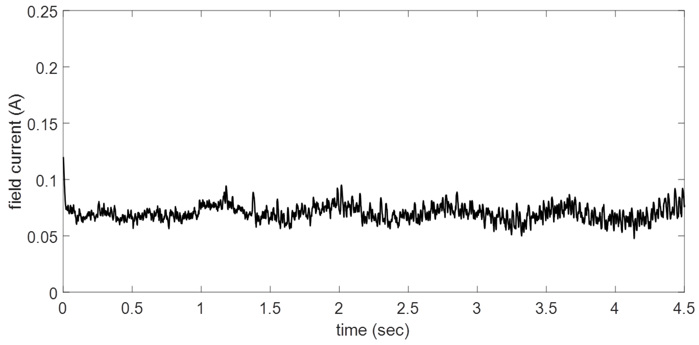
It is evident that the proposed controller confirms its faster response; therefore, it could maintain similar behavior for diverse disturbances and different system requirements. In this study, this is the only control variable; initially, the motor is operating at 52 rad/s with constant load torque. As a DC shunt motor, the field current is variable but the magnitude presented is less than the armature current (
Figure 13). This feature allows complex load torque specifications for variable rotor speeds. The behavior is a consequence of speed reference demands.
The performance and applicability of the proposition are proved by hardware implementation on a laboratory DC shunt motor. This strategy allows appropriately controlling the motor speed where the load and set point are modified and a trajectory tracking for velocity is required. The neural control is able to adapt by itself to different operating conditions; in other strategies, it is diminished in some situations, especially under different operating conditions for which its parameters have been tuned. Thus, the feedback signals to the BSNN are pertinent for a suitable control of the DC motor (shunt connected) velocity exhibiting a good performance for different operating points without modifications in control law. The noise observed in measurements is due to the type of speed sensor employed in this study. Thus, the introduced control scheme also presents a satisfactory performance for scenarios where measurement signals are corrupted by reasonable noise levels. Hence, the applicability of the proposed control approach has been demonstrated by real-life experimental results.


