
Alkaline Electrolysis for Hydrogen Production at Sea: Perspectives on Economic Performance

1
Departamento de Arquitectura, Construcción y Sistemas Oceánicos y Navales, Escuela Técnica Superior de Ingenieros Navales (ETSIN), Universidad Politécnica de Madrid (UPM), Avenida de la Memoria 4, 28040 Madrid, Spain
2
Grupo de Investigación de Pilas de Combustible, Tecnología del Hidrógeno y Motores Alternativos, Universidad Politécnica de Madrid, Avenida de la Memoria 4, 28040 Madrid, Spain
3
Departamento de Ingeniería Mecánica, Química y Diseño Industrial, Escuela Técnica Superior de Ingeniería y Diseño Industrial (ETSIDI), Universidad Politécnica de Madrid (UPM), Ronda de Valencia 3, 28012 Madrid, Spain
4
Departamento de Mecánica de Fluidos y Propulsión Aeroespacial, ETS Ingeniería Aeronáutica y del Espacio, Universidad Politécnica de Madrid, Plza. Cardenal Cisneros 3, 28040 Madrid, Spain
*
Author to whom correspondence should be addressed.
Energies 2023, 16(10), 4033; https://doi.org/10.3390/en16104033
Submission received: 10 April 2023
/
Revised: 5 May 2023
/
Accepted: 9 May 2023
/
Published: 11 May 2023
(This article belongs to the Special Issue Hydrogen Production from Organic Waste Water Electro-oxidation Processes)
Abstract
:Alkaline electrolysis is already a proven technology on land, with a high maturity level and good economic performance. However, at sea, little is known about its economic performance toward hydrogen production. Alkaline electrolysis units operate with purified water to split its molecules into hydrogen and oxygen. Purified water, and especially that sourced from the sea, has a variable cost that ultimately depends on its quality. However, the impurities present in that purified water have a deleterious effect on the electrolyte of alkaline electrolysis units that cause them to drop their energy efficiency. This, in turn, implies a source of economic losses resulting from the cost of electricity. In addition, at sea, there are various options regarding the electrolyte management, of which the cost depends on various factors. All these factors ultimately impact on the levelized cost of the produced hydrogen. This article aims to shed some light on the economic performance of alkaline electrolysis units operating under sea conditions, highlighting the knowledge gaps in the literature and initiating a debate in the field.
1. Introduction
Currently, the world scenario is heralding a paradigm shift within the energy system. Global society has been relying on fossil fuels as the main driver of the energy system due to their flexibility of use, transport and storage. However, their use comes with certain drawbacks that, given the current context, imply a point of concern:
- The use of fossil fuels as an energy source yields carbon dioxide (CO2) to the atmosphere, among other byproducts. It is believed that the raising concentration of carbon dioxide might be an important contributor to global warming [1].
- The use of fossil fuels typically yields other byproducts to the atmosphere that are harmful to different lifeforms, including humans. These byproducts include nitrogen oxides (NOx), sulfur oxides (Sox), volatile organic compounds (VOCs) and particulate matter (PM) [2].
- These byproducts, especially CO2, are also responsible for the acidification of the oceans, which have a direct impact on marine ecosystems [3].
- Fossil fuels are typically extracted in places that are subject to political instability, and as a result, their supply or price can suffer drastic variations, making economies that rely on them suffer these effects [4].
- It is no secret that the availability of fossil fuels is limited, and at some point, they will become scarce and more difficult to extract [5].
In the chase of carbon dioxide neutrality, hydrogen emerges as an alternative energy solution, with high prospects of applicability in those sectors that cannot be directly electrified, such as long-haul aviation, international shipping, high-temperature heat generation, long-term energy storage and seasonal energy storage of renewable energies [6].
Recently, it has been found that hydrogen can be naturally produced through different geological processes in the lithosphere [7]. Even though it might be very promising, the exploration of naturally generated hydrogen is at its infancy and not many places where this occurs are known; therefore, hydrogen must be produced. When hydrogen is produced by using renewable sources, literature has assigned the green label as per its origin [8]. At present, the green hydrogen production pathway that presents the highest maturity level is water electrolysis [9].
Due to strategic reasons, in very populated areas surrounded by the sea, it might be preferable to use land for purposes other than renewable energy harnessing and storage. This leaves the sea as the desirable spot for renewable energy harnessing. Should this be the case, then the production of hydrogen via electrolysis of water might make more sense in the marine environment, in a location close to renewable farms.
The use of electrolysis technologies at sea can be dated back to the appearance of nuclear-powered submarines, of which the air-independent propulsion eliminated the need for approaching the seawater surface to charge batteries via diesel gensets, and also removed the need for refueling throughout the vessel lifecycle due to the energy density of the nuclear fuel [10]. This technological breakthrough created the problem of the oxygen supply for the crew that manned the nuclear submarine, which previously relied on other endurance-restricted solutions such as oxygen candles [11] or oxygen storage on board [12]. Given that each water molecule contains one oxygen atom, it came as a logical solution to use part of the electricity generated by the nuclear power plant on board to split water molecules from the sea, to produce oxygen in an electrolyzer. This way, oxygen is generated and sent to the vessel atmosphere while disposing of the hydrogen byproduct out of the pressure hull of the submarine [13].
Even though water electrolysis technologies have proven feasible in marine environments due to their prolonged use in nuclear submarines, there are no disclosed reports on how well alkaline electrolysis (AE) or proton exchange membrane electrolysis (PEME) performs at sea from an economic point of view. In contrast, their economic performance on land has been well studied [14,15,16,17]. This unknown economic performance of AE or PEME units at sea might be one of the restraints that hinder their effective deployment at sea. In this sense, at present, it is difficult to compare hydrogen production costs at sea through water electrolysis with the equivalents on land, where all the data that have been obtained from actual experience; whereas at sea, estimations are based on assumptions [18,19,20].
One of the problems that arise when coupling an intermittent and variable renewable power source to an electrolysis system is that the inherent capacity factor of the renewable source will set the utilization factor of the electrolysis system [21]. If the nominal power of the electrolysis system is set as a fraction of the installed renewable power, its utilization factor could increase with respect to the capacity factor of the renewable farm. However, this strategy will lead to power curtailments whenever the power production surpasses the nominal power of the electrolysis system, which reduces the capacity factor of the farm. These low capacity factors and low utilization factors yield high hydrogen production costs [22]. Regardless of the electrolysis system and its inherent operation and management, one can try to drive down the costs by combining the electrolysis systems with more than one renewable power source, energy storage systems and connection to the hinterland’s grid via a power cable to keep the capacity factor of the renewable harnessing devices and the utilization factor of the electrolysis system at maximum levels [23]. However, this problem is left out of the scope of this perspective article as it deals more with power management strategies, rather than the operation and management of the electrolysis systems.
By developing advanced electrodes and diaphragm materials, and improving the cell designs, the efficiencies of the electrolysis devices can be further improved, which in turn, is expected to drop the hydrogen production costs. Efforts are being made in the research community toward this end [24,25,26,27,28], although in most cases, these new developments are still at a laboratory scale, meaning that to know their actual economic performance, more research work is required.
According to a multicriteria study developed by some of the authors of this article [29], low-temperature electrolysis technologies present the highest prospects of applicability at sea. This means that the PEME and AE present the highest chance of implementation, at least in the short term. It is worth highlighting that alkaline electrolysis can manage with a higher impurity content in feed water than PEME, as alkaline damage due to impurities is more reversible than the blistering that can occur in the MEA in the PEME [29]. This higher tolerance of AE toward the accumulation of impurities is useful considering that produced water from seawater will likely have a higher impurity content than water sourcing from fresh water sources. From another point of view, PEME could be favored in marine renewable contexts due to the higher current densities they feature and their ability to follow variable power production [22].
In 2021, the demonstration project, OCEANH2, started with the aim of designing and validating the first plant for offshore green hydrogen production, storage and distribution facility, based on alkaline electrolysis [30]. One of the goals of such a project is precisely obtaining enough real experience to obtain insight into the parameters that govern the economic performance of these type of installations at sea, to assess their profitability under a given configuration at sea with a higher accuracy, and to serve as a starting point for cost optimization strategies to drive the levelized cost of hydrogen production as low as possible.
Given the interest in producing hydrogen at sea from the electrolysis of water at a short term, with the focus on alkaline electrolysis, this article will discuss the economic problems that can arise from the marine operation of alkaline electrolysis systems for green hydrogen production at sea to open debate and encourage research in this field.
Currently, the estimated levelized cost of hydrogen production at sea from marine renewable energies is estimated to be in in the range of 2–15 EUR/kg, the capacity factor of renewable energy harnessing devices and the estimated cost of the electrolysis system being the main reasons behind this broad range [18,19,20]. In any case, this article covers only the operation and management decisions that may affect the resulting from a lifetime perspective.
The article is structured by first introducing the economic problem and the Key Performance Index (KPI) that defines it, along with a set of operating parameters that can have an effect on this KPI. To simplify the economic problem, the levelized cost of hydrogen () is systematically divided into different cost items. Then, the way in which the operating parameters affect their individual contribution to the overall is discussed for each item. To conclude, an overview matrix is displayed to highlight the areas that require more research effort.
2. Defining the Economic Problem
Among the key performance indices that can measure the economic behavior of any hydrogen production method, the most representative one is probably the levelized cost of hydrogen (), as it represents an estimation of the specific cost of hydrogen per unit of mass of the investment required in present monetary terms and the cost of operating the assets involved in its production. The can be summarized by:
The total mass of hydrogen can be estimated by integrating the mass flow rate of the produced hydrogen, , throughout the whole lifecycle, which can be calculated with the Faraday law of electrolysis:
where is the current density, is the active area of the electrolysis cell, represents the ratio of the amount of exchanged electrons by the amount of substance of hydrogen, is the Faraday constant, is the Faraday efficiency, is the number of stacked cells in the electrolysis stack and is the molar mass of hydrogen.
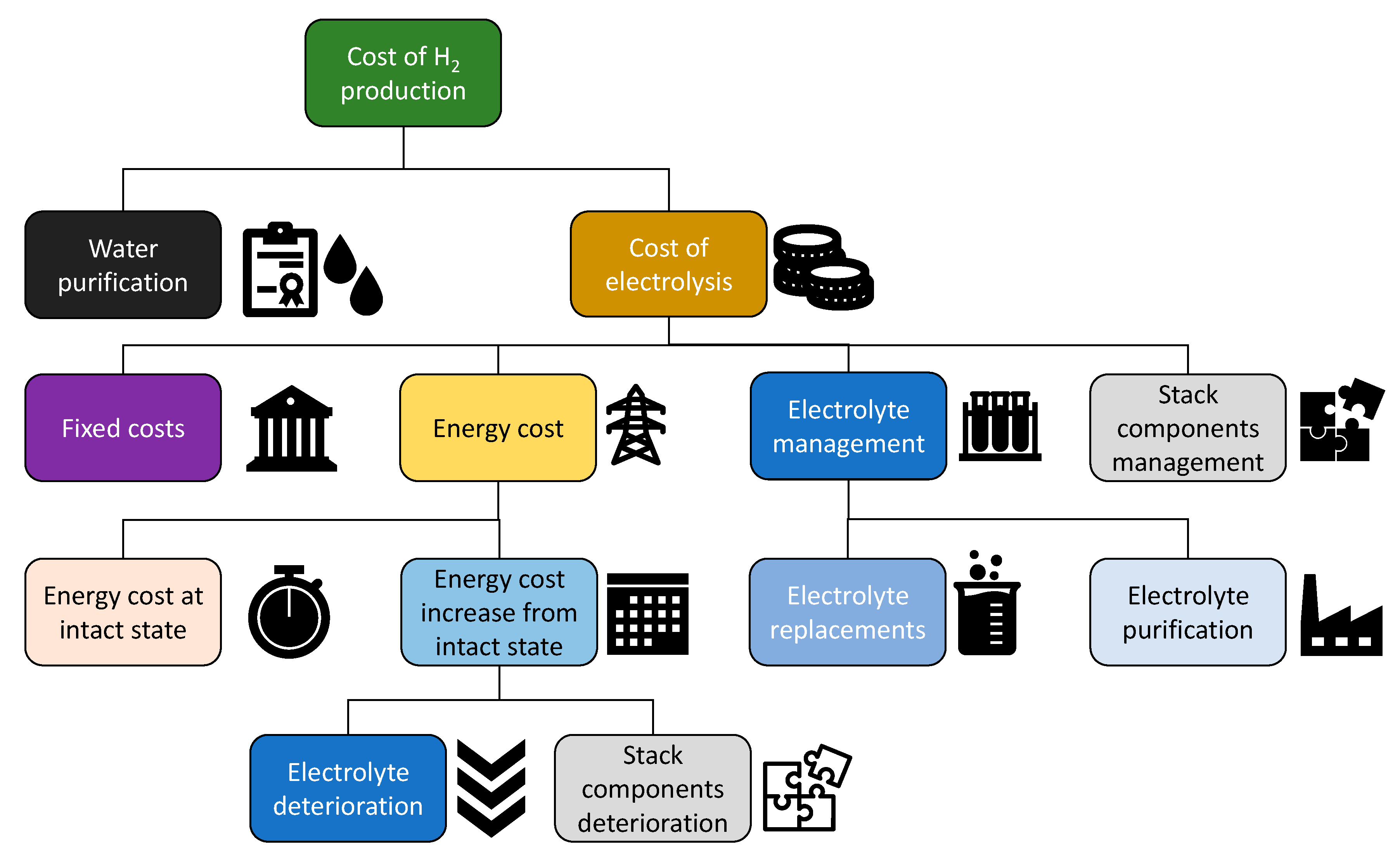
The first stage to understand how different operating parameters can affect the different cost items is to break down the total estimated lifecycle costs. Figure 1 proposes a convenient subdivision of the hydrogen production cost that will be detailed in the following subsections.
The parameters of which the influence on the different cost items depicted in Figure 1 are assessed are: water purity, current density, operating temperature, operating pressure and the time between electrolyte renewals.
2.1. Water Purification
Table 1 summarizes the typical cost of producing 1 m3 of desalinated water from seawater, and the typical impurity content in water [31,32]. As can be seen, there is a tendency to increase the cost of the product water when the impurity content decreases. The purity of the produced water obtained with reverse osmosis (from seawater) and electrodialysis (from brackish water) normally does not comply with the requirements of most manufacturers of electrolysis systems. Although distillation methods can yield water with a concentration of salts that comply with the requirements of some electrolyzer manufacturers (conductivities under 1 µS/cm), they often recommend even higher purities.
The produced desalinated water can be further processed to drive down the impurity content to values corresponding to ultrapure water, with salinity contents in the order of ppb and resistivities > 18.1 MΩ/cm, a resistivity that complies with pharmaceutical standards [33,34]. Processing desalinated seawater to increase water purity to comply with the standard for ultra-pure water, ASTM D5127 [34], can have a cost increase ranging from 2.38 to 5.28 USD/m3 [35]. In general, the cost of processed water is higher for a lower impurity content in input water.
At present, there is no standard in the industry to set a minimum purity quality of the feed water to be fed into the electrolysis system. However, different manufacturers specify a measure of conductivity or resistivity in feed water that they require and recommend. For instance, Nel requires a deionized water at a minimum ASTM D5127 Type II (>1 MΩ/cm), but recommends a deionized water at ASTM D5127 Type I (>10 MΩ/cm) [36].
The reason behind this recommendation lies in the fact that water impurities can contaminate the electrolytes in alkaline electrolysis systems, resulting in an increase in operating voltage that results in increased costs due to the raise in energy losses, precipitation of solids in the diaphragm pores and scaling on the electrodes [37]. In the case of PEM electrolysis, the accumulation of impurities in the recirculating water does not only increase the operating voltage at a given current density, but can also induce cell failure [38].
At present, it is believed that impurities present in feed water can affect the corrosion rate and the degradation rate of the components [29].
2.2. Cost of Electrolysis
Fixed Costs
Fixed costs involve all the costs that do not vary, regardless of the amount of hydrogen produced or the energy that they will consume. These costs include, among others, the right of use of the plot of sea or hire of the plot of land, the payroll of personnel, capital expenses and insurances. The capital expenses will depend linearly on the investment required. The required investment of centralized hydrogen production facilities based on alkaline technology for 2030 is expected to be in the interval of 400–500 EUR/kW [39]. However, in China it is expected to be closer to 135 USD/kW [20].
According to Equation (1), the higher the produced mass of H2, the lower the will be if the costs remain invariant, which is the case for the fixed costs. From the viewpoint of the , it is interesting to maximize the hydrogen production so that the fixed costs component gets diluted. It is therefore necessary to maximize to increment the production of hydrogen, since operating at higher current densities will not have an influence on the fixed costs. Alkaline electrolysis units typically operate between 0.20 and 0.40 A/cm2 [40].
From the technical and safety points of view, there is a minimum threshold of current density where all electrolysis technologies should not operate under, due to the crossover of hydrogen to the anode side of the cell and the analogue counterpart of oxygen to the cathode side [41]. This crossover can lead to dangerous potential mixtures within the flammability limits or even within the detonation limits. This can be solved by dividing the electrolysis plant into independent stack modules that can engage or disengage in operation to prevent any of the electrolyzers from operating under this minimum threshold of the current density.
From the technical point of view, it is not clear what current density could be applied to an electrolyzer as an upper limit [42]. It seems that if the cooling system is able to cope with the strongly exothermic regime at very high current densities, the electrolysis system will handle high current density operation for extended periods. If not, they would be operating under overload conditions. Overload operation for short periods is not only possible, but also advisable, as it has been found favorable for economizing hydrogen production [43]. The main problem of operating at higher current densities is that the electrolyzer incurs added energy losses due to the increased polarization, which is explained in further detail in the “Energy Costs” subsection. There is not enough research on how the current density affects the degradation of the electrolyzer components, although it is assumed that it could affect them somehow [44]. It can be argued that increasing the current density will increase the water consumption rate. This will in turn lead to a faster accumulation of impurities, of which the presence in the electrolyte can lead to direct performance loss and the deterioration of different components in the stack, such as scaling on the electrodes and pore clogging in the diaphragm.
2.3. Energy Costs
The energy cost is the energy consumed by the electrolysis system converted into monetary terms. For convenience, the energy cost is divided into the energy cost in an intact state, which is the energy that would be consumed by the electrolyzer if no degradation applies, and the energy cost increases from that state.
2.3.1. Energy Cost in an Intact State
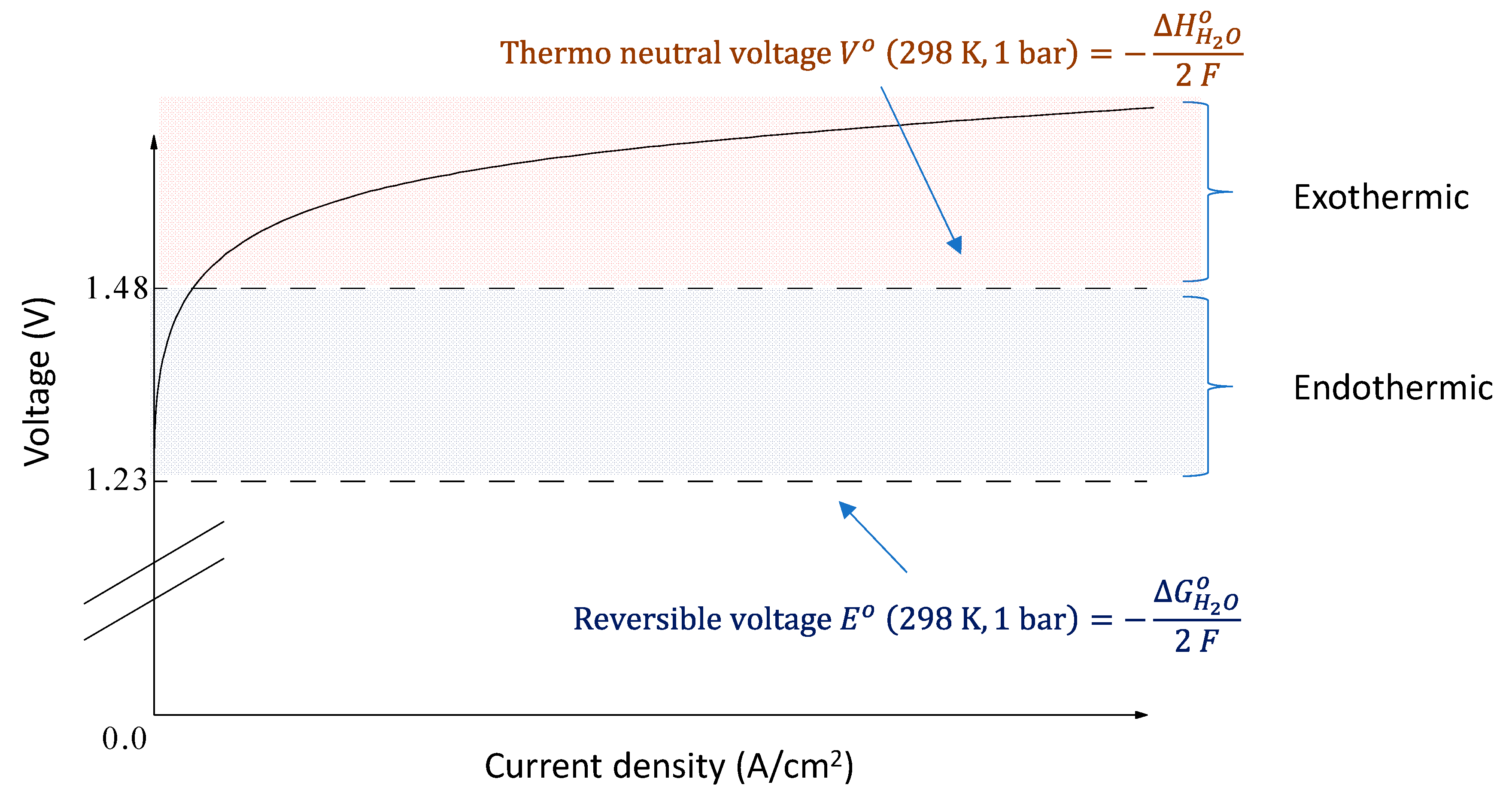
Figure 2 shows a generic polarization curve of an electrolysis cell for a given operating pressure and temperature. The polarization is the additional voltage (overvoltage) that has to be supplied to the electrolysis reaction from the reversible voltage to overcome the irreversibility. The difference in voltage from the reversible voltage multiplied by the applied current yields the power losses of each cell in an electrolysis stack. As the current density applied to the electrolysis reaction rises, the polarization (overvoltage), , increases, increasing the exothermic behavior and energy losses. This can be seen through one of the definitions of the thermal efficiency of the electrolysis reaction, [45]:
As the applied cell voltage, rises, the drops, leading to higher energy losses. represents the enthalpy increase in the electrolysis reaction, the thermoneutral voltage, the free Gibbs energy increment of the electrolysis reaction, the reversible voltage of the electrolysis reaction, the polarization (the overvoltage) from the reversible voltage and the voltage applied to a single cell. and are defined as a function of and , respectively, in Figure 2.
In the “Fixed Costs” subsection, it is argued that the higher the current density, , the lower the fixed costs contribution would be to the . In contrast, in this cost item, the energy cost in an intact state rises with the current density, , as the polarization, increases with the current density, . To reduce the energy cost in an intact state, the polarization, must be reduced, thus the current density, , must be reduced.
Finding what is the best tradeoff in current density will depend on the investment cost of the electrolysis system and the price of electricity. If the price of electricity were to be zero, then the minimum would be found at an indefinitely high current density, , regardless of the investment cost. For this reason, hypothetically, the lower the electricity price, the higher the current density, , will be, leading to the lowest .
Operation under pressure can reduce the size of the bubbles of product gases, improving the behavior at higher current densities [46]. In addition, the high pressures can increase the boiling temperature of the alkaline electrolyte, allowing for an increase in the operating temperature. In the literature, experimental pressurized electrolysis cells have been reported to operate between 150 and 200 °C, at current densities surpassing 3 A/cm2, while keeping the cell voltage under 1.8 V [47]. However, this mode of operation increases the crossover of product gases, leading to the earlier-described hazards related to achieving undesired flammable mixtures [48]. It is believed that increasing the operating temperature and pressure will increase the corrosion rate of the cell components [49].
2.3.2. Energy Cost Increase from an Intact State
This cost item adds to the energy cost in an intact state. The normal operation of the electrolysis cell will inevitably result in the degradation of the cell components yielding to a performance loss. The degradation can be a combination of different factors, such as component corrosion, electrolyte contamination, electrolyte loss through product gasses, diaphragm blockage, electrode scaling and others [50]. The performance loss is reflected as additional energy consumption, which can be observed through an additional overvoltage in the cell at a given temperature, pressure and current density [50]. Degradation can also be monitored in the form of resistance increase [37]. It is not clear how different factors affect the performance degradation over time. However, it seems that higher concentrations of the caustic electrolyte, higher temperatures and pressures, higher current densities and higher impurity content in feed water may accelerate the electrolyzer degradation [47,51,52]. There is not much literature covering the degradation problem, but different reports and studies agree that the trend in the voltage increase over time might be linear [37,53].
Water purity seems to be a key parameter in the degradation of an alkaline electrolyzer [53,54]. Impurities accumulate over time in the electrolyte increasing their concentration gradually. The rise in impurity concentration reduces the conductivity of the alkaline electrolyte, hence solids may precipitate in the diaphragm, clogging the pores and increasing the ionic resistance. Scaling may be produced on the electrodes, reducing their efficiency thanks to the accumulation of impurities in the electrolyte. Impurities might accelerate corrosion of different components [37]. The resulting performance loss of the electrolysis stack will result in an increased cost from an intact state.
Earlier, it was discussed that as a general rule, the higher the purity of the purified water, the higher its cost will be. Therefore, a tradeoff must be found between the cost of water purification and the energy cost increase from an intact state. It could be hypothesized that if the electricity price were to be lower, then the water purity required to reach that tradeoff could go down, meaning that it could have a higher impurity concentration, higher conductivity or lower resistivity.
To reset to the initial impurity electrolyte content state, the electrolyte can be replaced or purified. These tasks belong to the “Electrolyte Management” subsection and have an associated cost. Therefore, a tradeoff must be found between the energy cost increase from an intact state sourcing from the electrolyte deterioration and the electrolyte management cost. One of the parameters that can be optimized to find this tradeoff is the period between electrolyte renewals. This period will depend on how fast the energy cost increases from an intact state and how expensive it is to renew and/or purify the electrolyte. The results obtained in [37] suggest that the cost increases from an intact state at a constant rate. However, due to the accumulation of uncertainties in the methods used in [37], it is not possible to confirm the linear behavior of the energy cost increase from an intact state over time.
2.4. Electrolyte Management
Electrolyte management involves all the processes that aim to keep the electrolyte concentration at levels close to the initial state, along with the impurity content. Just by producing hydrogen through the electrolysis of water, part of the electrolyte is swept out of the system. It is estimated that about 1 mg of KOH leaves the system with the product gases for each 1 Nm3 of hydrogen produced [50]. Therefore, new electrolytes must be supplied gradually to compensate for this loss. Apart from that, impurities present in feed water tend to accumulate in the electrolyte, increasing the ohmic resistance to conduct ions. Impurities can also affect other components, such as the electrodes through scaling, the diaphragm through pore obstruction through precipitation and by speeding up the corrosion of different components. Increasing the expenditure in feed water purification will reduce the cost of electrolyte management. However, in the following lines, it is summarized why the tradeoff between feed water expenditure and electrolyte management expenditure is not possible to find, given the lack of research in this area.
2.4.1. Electrolyte Replacement
Replacing the electrolyte involves the acquisition of the electrolyte and its logistics, which will depend on the location of the hydrogen production facility relative to its closest hinterland port.
Another possibility when the electrolyte is based on NaOH is producing it locally from the rejected seawater brine from the water purification process through the chlor-alkali process [55]. This method removes the necessity of shipping and handling a concentrated caustic in a marine environment, which could be dangerous in rough weather conditions. For this reason, the electrolyte replacement operation would probably be restricted to days of calm weather. As discussed earlier, the period between electrolyte renewals will depend on how fast the cost of energy increases from an intact state and the acquisition and transport cost of the electrolyte replacement. After replacement, the energy cost increase from an intact state should reset to zero; however, a residual performance loss from an intact state could remain due to the deterioration of other stack components. Currently, the actual production cost of the in situ NaOH produced under this method is unknown in the literature. Therefore, it is not clear under what circumstances it is preferable to produce NaOH locally or bring new electrolytes from elsewhere.
To identify the tradeoff between electrolyte replacement and feed water purification, more research is required in the acquisition of caustic electrolytes from elsewhere and their logistics to the hydrogen production facility, in addition to the techno-economic studies on the local production of NaOH through a small auxiliary chlor-alkali process plant.
2.4.2. Electrolyte Purification
Precipitated solids suspended in the electrolyte can be easily removed by filtration.
Removing dissolved ions from the electrolyte for its purification can be attained through different processes. According to patent KR20180051887A [56], it is possible to remove cations other than Na+ by first concentrating the electrolyte until saturation and then bubbling chlorine, which immediately precipitates the chlorides of the cation impurities. Other patents use crystallization to remove impurities present in NaOH [57,58]. These types of purification strategies involve the use of ancillary equipment that will involve additional investment. All the purification equipment will consume additional space and energy, which will derive a set of lifecycle costs. Due to the lack of scientific literature covering electrolyte purification strategies, additional research is required to know if these types of strategies could effectively be placed in line, and what their cost repercussions will be.
Other metallic ions dissolved in the electrolyte can be removed by the electrowinning of a concentrated caustic, by controlling the temperature of the reaction [59]. This process seems easier to implement inline, but further research must be conducted to increase the techno-economic knowledge.
Most of the electrolyte purification processes are well known from the chlor-alkali industry, as the caustic liquor that is produced in the chlor-alkali cell requires certain purification steps. Therefore, producing NaOH locally might have synergies with the electrolyte purification strategy, as the same processes used for converting the caustic liquor could be used to remove the impurities in the electrolyte from the alkaline electrolysis plant for hydrogen production. Furthermore, one of the purification processes described above involved the use of chlorine gas, which is one of the products of the chlor-alkali process.
2.5. Stack Component Management
The electrolysis stack components are subject to accumulate damage in normal operation in the form of corrosion, scaling on the electrodes and diaphragm pore clogging, all which reflect on the energy cost increase from an intact state. It is not well studied how impurities in feed water, temperatures and pressures affect how fast components degrade, although it is hypothesized that they could be affected by increasing the degradation speed. Analogously to the electrolyte, in theory, it should be possible to recover the intact state of the electrolyzer by replacing or maintaining the components. At some point in the life of the electrolysis stack, the components can be replaced to recover the initial efficiency of the stack. Replacing components would probably require stopping the stack operation for a certain period for overhauling. However, it is not known what the economic repercussions of these procedures may imply, and if it would be more cost-effective than replacing the full stack while selling the degraded one for scrapping.
There might be other refurbishment strategies that could avoid the disassembly of the stack. Patent CN113862727A [60] describes a method for cleaning the accumulated scaling on the cathode electrodes by using a set of different steps that involve wash cycles with water, acidic water and the use of electroplating solution, which theoretically recovers the initial performance of these electrodes. However, methods such as this would require the rest of the electrolyzer components to be compatible with the different chemicals required for the process.
The economic implications of using the first or the second strategy are not known and need for more research. In addition, it is not clear if altering specific parameters such as the operation temperature and/or pressure, electrolyte concentration, current density and period between electrolyte renewals affects the degradation of the stack components, and to what extent this degradation will result in an energy cost increase from an intact state.
3. Conclusions
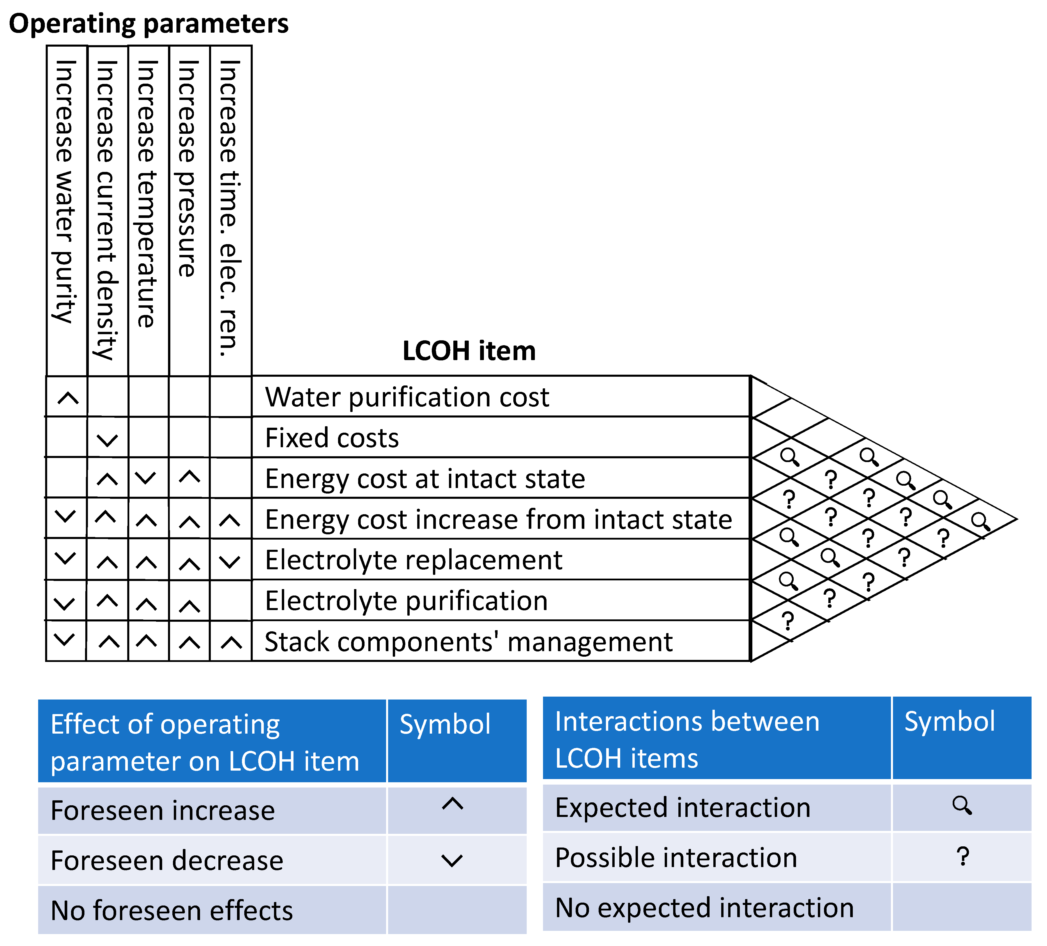
Figure 3 summarizes how different parameters of the electrolysis reaction are expected to affect different cost items within the levelized cost of hydrogen (), and which cost items are expected to interact with each other and the existence of these expected interactions, classified as two different certainly levels.
The explanation of how the matrix should be read is done through examples. Starting by how the operating parameters can affect the different items, the matrix in Figure 3 must be read from top left to right. For instance, an increase in water purity is foreseen to increase the water purification cost, but expected to reduce the energy cost increase from an intact state. Going to the triangular matrix to the right, it can be checked if actuations on different cost items will have interactions between them. The intersection cell between water purification cost and energy cost increase from an intact state shows a magnifying glass. This means that there is an expected interaction, implying that there might be at least one operating parameter onto which a tradeoff must be found to optimize the overall . Empty intersection cells, such as the one between water purification costs and fixed costs, shows that no interaction is expected. Cells with a question mark such as the intersection between fixed costs and energy cost increase from intact state, show a possible existing interaction with a lower certainty degree than the magnifying glass. In this case, the question mark reflects that there might be certain more expensive electrolyzer materials that may reduce their degradation over time. A potential tradeoff requires more research effort to be found. The question mark also implies higher research requirements in order to clarify the existence of possible interactions between the cost items, the involved operating parameters and their tradeoff.
All these factors ultimately impact on the final to a higher or lower degree. The main problem arises when one single parameter has opposed effects on various cost items, which causes an indetermination problem where a tradeoff must be found. As can be seen, the cost optimization problem is inherently complex and requires a multidisciplinary approach. Optimizing one single cost item would probably end in a non-optimal overall. More research is required to gain insight into the interaction between different cost items and determine what the best management strategy will be when different approaches are followed. Therefore, once it is clear how the different parameters and management decisions affect the different cost items, a holistic approach should be followed toward determining the best strategies to yield the lowest possible. The best strategy will vary depending on the boundary conditions, which will certainly change over time and location.
There is still a need for more research to know how alkaline electrolysis systems perform economically at sea. This knowledge will be useful to unveil how they compare with their on-land equivalents in terms of . To this end, extensive laboratory experiments must be conducted to obtain detailed economic models of all the items. Once this is done, it could be possible to perform a detailed economic analysis with a relatively high accuracy.
Author Contributions
Conceptualization, R.d.-D.; methodology, R.d.-D.; validation, I.C., E.N. and T.J.L.; formal analysis, R.d.-D.; investigation, R.d.-D.; data curation, R.d.-D.; writing—original draft preparation, R.d.-D.; writing—review and editing, I.C., E.N. and T.J.L.; visualization, R.d.-D.; supervision, T.J.L.; project administration, T.J.L.; funding acquisition, T.J.L. All authors have read and agreed to the published version of the manuscript.
Funding
This research and the APC were funded by the Spanish Ministry of Science and Innovation through the State Agency for Research and European Regional Development Funds through the Research Project PID2021-124263OB-I00 funded by MCIN/AEI/10.13039/501100011033 and “ERDF a way of making Europe”.
Data Availability Statement
No new data were created or analyzed in this study. Data sharing is not applicable to this article.
Acknowledgments
The authors acknowledge the Spanish Ministry of Science and Innovation through the State Agency for Research and European Regional Development Funds through the Research Project PID2021-124263OB-I00 funded by MCIN/AEI/10.13039/501100011033 and “ERDF a way of making Europe”. Special thanks are given to Fernando Acción from the Universidad Complutense de Madrid.
Conflicts of Interest
The authors declare no conflict of interest.
References
- Yoro, K.O.; Daramola, M.O. CO2 emission sources, greenhouse gases, and the global warming effect. In Advances in Carbon Capture; Elsevier: Amsterdam, The Netherlands, 2020; pp. 3–28. [Google Scholar]
- Tokuslu, A.; Bayirhan, I.; Gaziglu, C. Investigation the effect of sox emission reduction on transit ships emissions as of January 1, 2020. Therm. Sci. 2020, 24, 149–155. [Google Scholar] [CrossRef]
- Villalobos, C.; Love, B.A.; Olson, M.B. Ocean acidification and ocean warming effects on Pacific Herring (Clupea pallasi) early life stages. Front. Mar. Sci. 2020, 7, 597899. [Google Scholar] [CrossRef]
- Awosusi, A.A.; Rjoub, H.; Dördüncü, H.; Kirikkaleli, D. Does the potency of economic globalization and political instability reshape renewable energy usage in the face of environmental degradation? Environ. Sci. Pollut. Res. 2023, 30, 22686–22701. [Google Scholar] [CrossRef]
- Bardi, U. Peak oil, 20 years later: Failed prediction or useful insight? Energy Res. Soc. Sci. 2019, 48, 257–261. [Google Scholar] [CrossRef]
- IRENA. Global Hydrogen Trade to Meet the 1.5 °C Climate Goal. Part II: Technology Review of Hydrogen Carriers; IRENA: Abhu Dhabi, United Arab Emirates, 2022. [Google Scholar]
- Wang, L.; Jin, Z.; Chen, X.; Su, Y.; Huang, X. The Origin and Occurrence of Natural Hydrogen. Energies 2023, 16, 2400. [Google Scholar] [CrossRef]
- International Energy Agency. The Future of Hydrogen: Seizing Today’s Opportunities. 2019. Available online: https://www.oecd-ilibrary.org/energy/the-future-of-hydrogen_1e0514c4-en (accessed on 1 March 2023). [CrossRef]
- Ishaq, H.; Dincer, I.; Crawford, C. A review on hydrogen production and utilization: Challenges and opportunities. Int. J. Hydrogen Energy 2022, 47, 26238–26264. [Google Scholar] [CrossRef]
- Weybrew, B.B. Three decades of nuclear submarine research: Implications for space and Antarctic research. In From Antarctica to Outer Space; Springer: Berlin/Heidelberg, Germany, 1991; pp. 103–114. [Google Scholar]
- Markowitz, M.M.; Boryta, D.A.; Stewart, H.J. Lithium Perchlorate Oxygen Candle. Pyrochemical Source of Pure Oxygen. I&EC Prod. Res. Dev. 1964, 3, 321–330. [Google Scholar] [CrossRef]
- Shadle, T.; Daley, T.U.S. Navy Submarine Life Support Systems; SAE International: Warrendale, PA, USA, 1991. [Google Scholar] [CrossRef]
- Leonida, A.; McElroy, J.F.; Sexauer, R.N. A low pressure electrolyzer for the next generation submarine. SAE Trans. 1992, 101, 409–413. [Google Scholar]
- Nami, H.; Rizvandi, O.B.; Chatzichristodoulou, C.; Hendriksen, P.V.; Frandsen, H.L. Techno-economic analysis of current and emerging electrolysis technologies for green hydrogen production. Energy Convers. Manag. 2022, 269, 116162. [Google Scholar] [CrossRef]
- Motazedi, K.; Salkuyeh, Y.K.; Laurenzi, I.J.; MacLean, H.L.; Bergerson, J.A. Economic and environmental competitiveness of high temperature electrolysis for hydrogen production. Int. J. Hydrog. Energy 2021, 46, 21274–21288. [Google Scholar] [CrossRef]
- Terlouw, T.; Bauer, C.; McKenna, R.; Mazzotti, M. Large-scale hydrogen production via water electrolysis: A techno-economic and environmental assessment. Energy Environ. Sci. 2022, 15, 3583–3602. [Google Scholar] [CrossRef]
- Ordóñez, D.F.; Shah, N.; Guillén-Gosálbez, G. Economic and full environmental assessment of electrofuels via electrolysis and co-electrolysis considering externalities. Appl. Energy 2021, 286, 116488. [Google Scholar] [CrossRef]
- Perna, A.; Jannelli, E.; Di Micco, S.; Romano, F.; Minutillo, M. Designing, sizing and economic feasibility of a green hydrogen supply chain for maritime transportation. Energy Convers. Manag. 2023, 278, 116702. [Google Scholar] [CrossRef]
- Jang, D.; Kim, K.; Kim, K.-H.; Kang, S. Techno-economic analysis and Monte Carlo simulation for green hydrogen production using offshore wind power plant. Energy Convers. Manag. 2022, 263, 115695. [Google Scholar] [CrossRef]
- Song, S.; Lin, H.; Sherman, P.; Yang, X.; Nielsen, C.P.; Chen, X.; McElroy, M.B. Production of hydrogen from offshore wind in China and cost-competitive supply to Japan. Nat. Commun. 2021, 12, 6953. [Google Scholar] [CrossRef] [PubMed]
- Armijo, J.; Philibert, C. Flexible production of green hydrogen and ammonia from variable solar and wind energy: Case study of Chile and Argentina. Int. J. Hydrog. Energy 2020, 45, 1541–1558. [Google Scholar] [CrossRef]
- Egeland-Eriksen, T.; Jensen, J.F.; Ulleberg, Ø.; Sartori, S. Simulating offshore hydrogen production via PEM electrolysis using real power production data from a 2.3 MW floating offshore wind turbine. Int. J. Hydrog. Energy 2023, in press. [Google Scholar] [CrossRef]
- Singlitico, A.; Østergaard, J.; Chatzivasileiadis, S. Onshore, offshore or in-turbine electrolysis? Techno-economic overview of alternative integration designs for green hydrogen production into Offshore Wind Power Hubs. Renew. Sustain. Energy Transit. 2021, 1, 100005. [Google Scholar] [CrossRef]
- Chen, J.; Zhang, L.; Li, J.; He, X.; Zheng, Y.; Sun, S.; Fang, X.; Zheng, D.; Luo, Y.; Wang, Y.; et al. High-efficiency overall alkaline seawater splitting: Using nickel-iron sulfide nanosheet array as a bifunctional electrocatalyst. J. Mater. Chem. A 2023, 11, 1116–1122. [Google Scholar] [CrossRef]
- Fang, X.; Wang, X.; Ouyang, L.; Zhang, L.; Sun, S.; Liang, Y.; Luo, Y.; Zheng, D.; Kang, T.; Liu, Q.; et al. Amorphous Co-Mo-B Film: A High-Active Electrocatalyst for Hydrogen Generation in Alkaline Seawater. Molecules 2022, 27, 7617. [Google Scholar] [CrossRef]
- Zhang, K.; Liang, X.; Wang, L.; Sun, K.; Wang, Y.; Xie, Z.; Wu, Q.; Bai, X.; Hamdy, M.S.; Chen, H.; et al. Status and perspectives of key materials for PEM electrolyzer. Nano Res. Energy 2022, 1, e9120032. [Google Scholar] [CrossRef]
- Liu, Q.; Sun, S.; Zhang, L.; Luo, Y.; Yang, Q.; Dong, K.; Fang, X.; Zheng, D.; Alshehri, A.A.; Sun, X. N, O-doped carbon foam as metal-free electrocatalyst for efficient hydrogen production from seawater. Nano Res. 2022, 15, 8922–8927. [Google Scholar] [CrossRef]
- Gao, F.; He, J.; Wang, H.; Lin, J.; Chen, R.; Yi, K.; Huang, F.; Lin, Z.; Wang, M. Te-mediated electro-driven oxygen evolution reaction. Nano Res. Energy 2022, 1, e9120029. [Google Scholar] [CrossRef]
- D’Amore-Domenech, R.; Santiago, Ó.; Leo, T.J. Multicriteria analysis of seawater electrolysis technologies for green hydrogen production at sea. Renew. Sustain. Energy Rev. 2020, 133, 110166. [Google Scholar] [CrossRef]
- Acciona. Arranca el Proyecto de Investigación Industrial OCEANH2, Coordinado por ACCIONA 2021. Available online: https://www.acciona.com/es/actualidad/articulos/arranca-proyecto-investigacion-industrial-oceanh2-coordinado-acciona/?_adin=02021864894 (accessed on 22 March 2023).
- Manchanda, H.; Kumar, M. Study of water desalination techniques and a review on active solar distillation methods. Environ. Prog. Sustain. Energy 2018, 37, 444–464. [Google Scholar] [CrossRef]
- Do Thi, H.T.; Pasztor, T.; Fozer, D.; Manenti, F.; Toth, A.J. Comparison of Desalination Technologies Using Renewable Energy Sources with Life Cycle, PESTLE, and Multi-Criteria Decision Analyses. Water 2021, 13, 3023. [Google Scholar] [CrossRef]
- Libman, S.; Wilcox, D.; Zerfas, B. Ultrapure water for advance semiconductor manufacturing: Challenges and opportunities. ECS Trans. 2015, 69, 17. [Google Scholar] [CrossRef]
- Melnik, L.A.; Krysenko, D.A. Ultrapure water: Properties, production, and use. J. Water Chem. Technol. 2019, 41, 143–150. [Google Scholar] [CrossRef]
- Lee, H.; Jin, Y.; Hong, S. Recent transitions in ultrapure water (UPW) technology: Rising role of reverse osmosis (RO). Desalination 2016, 399, 185–197. [Google Scholar] [CrossRef]
- Nel. Nel FAQ-What Water Quality Do I Need? 2023. Available online: https://nelhydrogen.com/faq/ (accessed on 25 March 2023).
- d’Amore Domenech, R. Study on the Production of Hydrogen through the Electrolysis of Seawater in a Sustainable Marine Context. Ph.D. Thesis, Universidad Politécnica de Madrid, Madrid, Spain, 2021. [Google Scholar]
- Yoshimura, R.; Wai, S.; Ota, Y.; Nishioka, K.; Suzuki, Y. Effects of Artificial River Water on PEM Water Electrolysis Performance. Catalysts 2022, 12, 934. [Google Scholar] [CrossRef]
- Küfeoğlu, S. From Hydrogen Hype to Hydrogen Reality: A Horizon Scanning for the Business Opportunities; C-EENRG Working Papers; Cambridge Centre for Environment, Energy and Natural Resource Governance, University of Cambridge: Cambridge, UK, 2023; pp. 1–94. [Google Scholar]
- Vidas, L.; Castro, R. Recent Developments on Hydrogen Production Technologies: State-of-the-Art Review with a Focus on Green-Electrolysis. Appl. Sci. 2021, 11, 1363. [Google Scholar] [CrossRef]
- Brauns, J.; Turek, T. Alkaline Water Electrolysis Powered by Renewable Energy: A Review. Processes 2020, 8, 248. [Google Scholar] [CrossRef]
- Fischer, M. Review of hydrogen production with photovoltaic electrolysis systems. Int. J. Hydrog. Energy 1986, 11, 495–501. [Google Scholar] [CrossRef]
- Smolinka, T.; Ojong, E.T.; Garche, J. Chapter 8—Hydrogen Production from Renewable Energies—Electrolyzer Technologies. In Electrochemical Energy Storage for Renewable Sources and Grid Balancing; Moseley, P.T., Garche, J., Eds.; Elsevier: Amsterdam, The Netherlands, 2015; pp. 103–128. [Google Scholar] [CrossRef]
- Jothi, V.R.; Karuppasamy, K.; Maiyalagan, T.; Rajan, H.; Jung, C.-Y.; Yi, S.C. Corrosion and Alloy Engineering in Rational Design of High Current Density Electrodes for Efficient Water Splitting. Adv. Energy Mater. 2020, 10, 1904020. [Google Scholar] [CrossRef]
- Lamy, C.; Millet, P. A critical review on the definitions used to calculate the energy efficiency coefficients of water electrolysis cells working under near ambient temperature conditions. J. Power Sources 2020, 447, 227350. [Google Scholar] [CrossRef]
- Mazloomi, S.K.; Sulaiman, N. Influencing factors of water electrolysis electrical efficiency. Renew. Sustain. Energy Rev. 2012, 16, 4257–4263. [Google Scholar] [CrossRef]
- Lohmann-Richters, F.P.; Renz, S.; Lehnert, W.; Müller, M.; Carmo, M. Challenges and Opportunities for Increased Current Density in Alkaline Electrolysis by Increasing the Operating Temperature. J. Electrochem. Soc. 2021, 168, 114501. [Google Scholar] [CrossRef]
- Trinke, P.; Haug, P.; Brauns, J.; Bensmann, B.; Hanke-Rauschenbach, R.; Turek, T. Hydrogen crossover in PEM and alkaline water electrolysis: Mechanisms, direct comparison and mitigation strategies. J. Electrochem. Soc. 2018, 165, F502. [Google Scholar] [CrossRef]
- Hu, S.; Liu, R.; Liu, L.; Cui, Y.; Wang, F. Influence of temperature and hydrostatic pressure on the galvanic corrosion between 90/10 Cu–Ni and AISI 316L stainless steel. J. Mater. Res. Technol. 2021, 13, 1402–1415. [Google Scholar] [CrossRef]
- Godula-Jopek, A. Hydrogen Production by Electrolysis; John Wiley & Sons: Hoboken, NJ, USA, 2015. [Google Scholar]
- Becker, H.; Murawski, J.; Shinde, D.V.; Stephens, I.E.L.; Hinds, G.; Smith, G. Impact of impurities on water electrolysis: A review. Sustain. Energy Fuels 2023, 7, 1565–1603. [Google Scholar] [CrossRef]
- Chauhan, D.; Ahn, Y.-H. Alkaline electrolysis of wastewater and low-quality water. J. Clean Prod. 2023, 397, 136613. [Google Scholar] [CrossRef]
- Amores, E.; Sánchez, M.; Sánchez-Molina, M.; Sevilla, G.; Ortega, J. Efecto de la composición del agua de mar en la electrólisis alcalina para la producción de hidrógeno en aplicaciones off-shore. In Congreso Iberoamericano de Hidrógeno y Pilas de Combustible (Iberconappice); Daza Bertrand, M., Daza Bertrand, L., Eds.; Asociación Española de Pilas de Combustible—APPICE: Madrid, Spain, 2019; pp. 104–110. [Google Scholar]
- Amores, E.; Sánchez, M.; Rojas, N.; Sánchez-Molina, M. 9—Renewable hydrogen production by water electrolysis. In Mustansar Hussain CBT-SFTH; Dutta, S., Ed.; Academic Press: Cambridge, MA, USA, 2021; pp. 271–313. [Google Scholar] [CrossRef]
- d’Amore-Domenech, R.; Navarro, E.; Mora, E.; Leo, T.J.T.J. Alkaline Electrolysis at Sea for Green Hydrogen Production: A Solution to Electrolyte Deterioration. Proc. Int. Conf. Offshore Mech. Arct. Eng. OMAE 2018, 10, V010T09A014. [Google Scholar] [CrossRef]
- Ryu, J. Method for Removing Metallic Impurity Present in NaOH. 2016. Available online: https://patents.google.com/patent/KR20180051887A/en?oq=KR20180051887A (accessed on 1 March 2023).
- Purifn of Sodium Hydroxide Solns—By Cooling to Supersaln, Pptg Crystals, Classifying and Removing Impure Crystals with Classifying Soln 1974. Available online: https://patents.google.com/patent/FR2263977A1/en?oq=FR2263977A1 (accessed on 1 March 2023).
- Schlafer, D.; Mauss, M.; Rauls, M.; Baumann, D. Purification of Caustic Soda 2000. Available online: https://patents.google.com/patent/US6113657A/en?oq=us6113657 (accessed on 1 March 2023).
- Joo, J.; Kim, J.; Kim, J.W.; Ocon, J.D.; Lee, J.K.; Chang, W.; Lee, J. Ultrahigh purification in concentrated NaOH by electrowinning for solar cell application. Sep. Purif. Technol. 2015, 145, 24–28. [Google Scholar] [CrossRef]
- Yu, Z.; Wang, J.; Wang, F.; Zhang, C.; Ren, Z.; Wang, P. Cleaning and Regenerating Method of Alkaline Electrolysis Hydrogen Production Cathode Net 2021:7. Available online: https://patents.google.com/patent/CN113862727A/en?oq=CN113862727A+ (accessed on 1 March 2023).
Figure 1.
Proposed subdivision of the cost of hydrogen production in a marine environment. In this work, the intact state refers to the state where no damage has been produced to any of the components.
Figure 1.
Proposed subdivision of the cost of hydrogen production in a marine environment. In this work, the intact state refers to the state where no damage has been produced to any of the components.

Figure 2.
Generic polarization curve of the electrolysis reaction. The higher the current density, the higher the polarization will be. This will increase exothermic behavior and cost due to energy consumption.
Figure 2.
Generic polarization curve of the electrolysis reaction. The higher the current density, the higher the polarization will be. This will increase exothermic behavior and cost due to energy consumption.

Figure 3.
Overview of how different parameters are expected to affect different cost items within the levelized cost of hydrogen (), and interactions between the cost items.
Figure 3.
Overview of how different parameters are expected to affect different cost items within the levelized cost of hydrogen (), and interactions between the cost items.


Table 1.
Summary of water production cost and typical impurity content in product water from seawater, and brackish water in the case of electrodialysis [31,32]. The broad cost intervals could be due to the existence of scale economies or thediverse costs of input energy.
| Unit Cost (USD/m3) | Impurity Content (ppm) | |
|---|---|---|
| Multieffect distillation | 0.52–8.00 | ~10 |
| Multistage flash distillation | 0.52–1.75 | ~10 |
| Vapor compression distillation | 2.00–2.60 | ~10 |
| Reverse osmosis | 0.48–1.60 | <500 |
| Electrodialysis | 0.60–1.05 | 150–500 |
Disclaimer/Publisher’s Note: The statements, opinions and data contained in all publications are solely those of the individual author(s) and contributor(s) and not of MDPI and/or the editor(s). MDPI and/or the editor(s) disclaim responsibility for any injury to people or property resulting from any ideas, methods, instructions or products referred to in the content. |
© 2023 by the authors. Licensee MDPI, Basel, Switzerland. This article is an open access article distributed under the terms and conditions of the Creative Commons Attribution (CC BY) license (https://creativecommons.org/licenses/by/4.0/).
Share and Cite
MDPI and ACS Style
d’Amore-Domenech, R.; Carrillo, I.; Navarro, E.; Leo, T.J. Alkaline Electrolysis for Hydrogen Production at Sea: Perspectives on Economic Performance. Energies 2023, 16, 4033. https://doi.org/10.3390/en16104033
AMA Style
d’Amore-Domenech R, Carrillo I, Navarro E, Leo TJ. Alkaline Electrolysis for Hydrogen Production at Sea: Perspectives on Economic Performance. Energies. 2023; 16(10):4033. https://doi.org/10.3390/en16104033
Chicago/Turabian Styled’Amore-Domenech, Rafael, Isabel Carrillo, Emilio Navarro, and Teresa J. Leo. 2023. "Alkaline Electrolysis for Hydrogen Production at Sea: Perspectives on Economic Performance" Energies 16, no. 10: 4033. https://doi.org/10.3390/en16104033
Note that from the first issue of 2016, this journal uses article numbers instead of page numbers. See further details here.