
A Comprehensive Review of the Role of CO2 Foam EOR in the Reduction of Carbon Footprint in the Petroleum Industry


Center for Petroleum Science and Engineering, Skolkovo Institute of Science and Technology, 121205 Moscow, Russia
*
Author to whom correspondence should be addressed.
†
These authors contributed equally to this work.
Energies 2023, 16(3), 1167; https://doi.org/10.3390/en16031167
Submission received: 26 December 2022
/
Revised: 16 January 2023
/
Accepted: 17 January 2023
/
Published: 20 January 2023
(This article belongs to the Special Issue The Optimization of Well Testing Operations for Oil and Gas Field)
Abstract
:By trapping CO2 and storing it in matured and depleted geological formations, atmospheric CO2 release can be reduced. Carbon capture and storage on a large scale can help to stabilize atmospheric greenhouse gas emissions. This can be achieved by using anthropogenic CO2 for enhanced oil recovery (EOR), which encourages advances in secure CO2 storage while enhancing the oil production process. This interaction is expected to hasten the development of CO2 storage technology and lower emissions from oil producing operations. Reducing CO2 mobility in the reservoir is crucial to achieving this goal as effectively as possible, and in situ foam generation offers a viable solution. It has been shown that implementing a blend of CO2 and foaming solution considerably reduces CO2 mobility and front propagation. Although there have been a few reviews of carbon capture, utilization, and storage (CCUS), none of these have concentrated on the role of foam EOR in achieving carbon neutrality. Therefore, in this brief review, methods for achieving carbon neutrality with foam EOR are comprehensively reviewed. In order to store CO2, the utilisation of atmospheric CO2 to generate foam is the main topic of this review. This approach can boost financial incentives for the energy sector, help to lower carbon emissions, and make it possible to produce oil from depleted reservoirs in a more sustainable way. Thus, identifying and examining the governing mechanisms that affect CO2 storage during foam flooding as well as reviewing the various techniques for estimating CO2 storage under actual reservoir circumstances are among the goals of this work.
1. Introduction
The term “carbon footprint” refers to greenhouse gas emissions. Their decrease is crucial, as it lessens the impact of climate change, thereby benefiting human health and the diversity of plants and animals [1,2]. Additionally, it promotes the global economy by producing creative and environmentally responsible solutions. In general, the top three sources of CO emissions are coal, oil, and natural gas [3]. The percentage compositions of carbon in these sources are 60–80%, 82–85%, and about 87%, respectively [3,4,5,6]. Thus, because carbon is a key component, cutting back on consumption- or production-related emissions has a significant positive impact on the environment, economy, and public health. The gases that contribute to the greenhouse effect are listed as follows with their corresponding percentage compositions: carbon dioxide (79%); methane (11%); nitrous oxide (7%); and fluorinated gases (3%) [7,8,9]. Thus, as the primary component of greenhouse gas emissions, CO emissions in particular are viewed as a challenging problem that must be resolved [10].
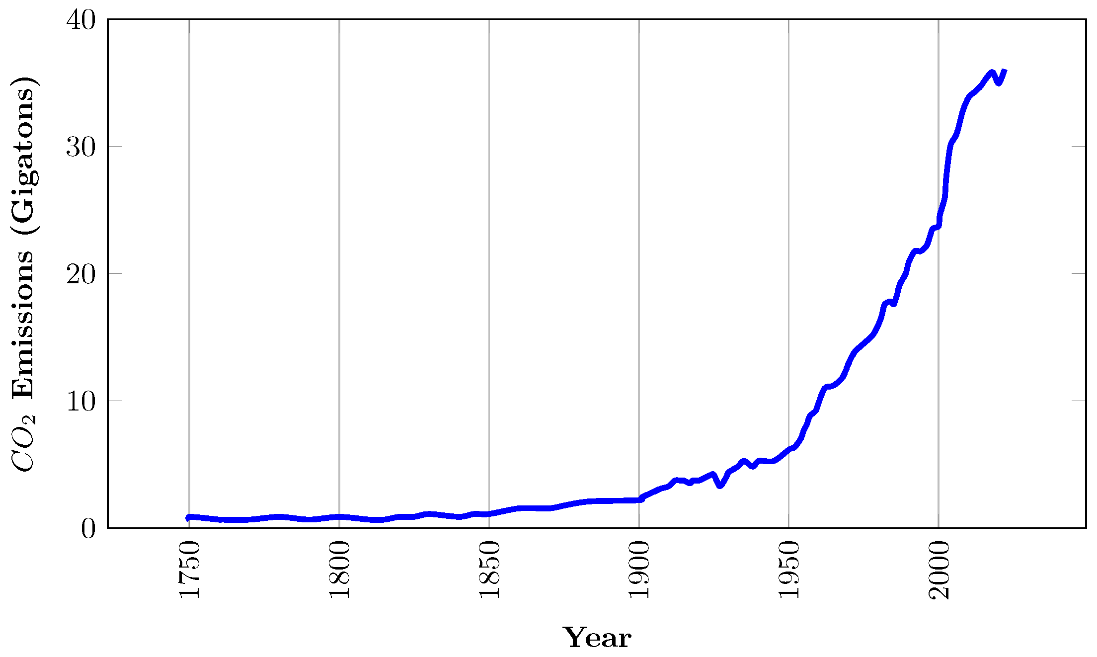
In 2021, CO emissions from industrial activities and the combustion of energy increased to their greatest annual level [11]. Emissions increased by 6% from 2020 to 36.3 gigatons (Figure 1). However, it should be considered that energy consumption in 2020 was significantly impacted by the COVID-19 pandemic, which resulted in a 5.2% decrease in global CO emissions. Subsequently, the global economy has recovered incredibly quickly thanks to massive fiscal and monetary support as well as a quick mobilization of vaccines [11,12]. The development of global emissions from the middle of the 18th century to date is seen in the figure above. It can be observed that emissions were very minimal before the industrial revolution, and emissions growth remained comparatively slow until the middle of the 20th century [13,14]. The globe released about 6 billion tonnes of CO in 1950. This amount increased nearly four-fold by 1990, rising to over 22 billion tonnes (Figure 1). Recently, CO emissions stand at more than 34 billion tonnes annually as a result of the rapid increase of these emissions [11,15].
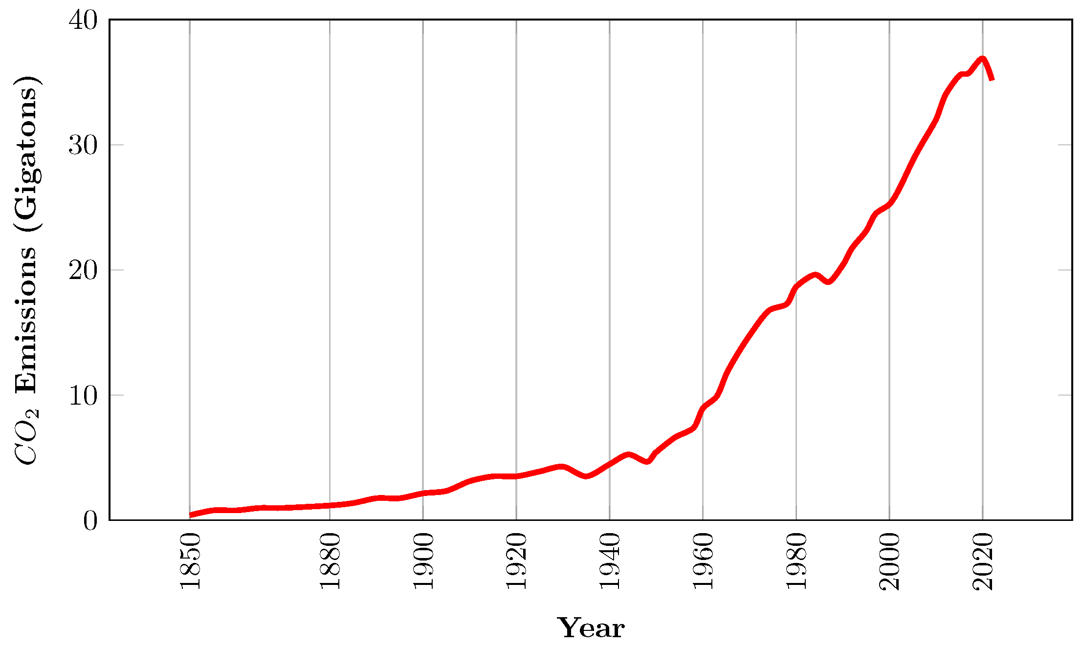
Figure 2 shows the increase in worldwide emissions due to fossil fuels from the middle of the 18th Century to the present. As can be seen, emissions from fossil fuels have significantly increased. Overall, this indicates that overall emissions have essentially stabilised during the past ten years.
In the petroleum industry, CO capture and storage (CCS) in appropriate reservoir formations can reduce atmospheric CO accumulation. Globally, subsurface storage for CO could be at least 2000 gigatonnes [16,17]. This is eighty times more than annual CO emissions. The stabilization of atmospheric greenhouse gas concentrations can be aided by extensive CCS implementations [18]. CCS is frequently mentioned as a solution to permanently store carbon dioxide emissions from large polluters underground, thereby keeping them out of the atmosphere [19]. However, CCS can be utilized in a more economical way to produce crude oil, which when burned releases emissions and contributes to climate change. Using CO emitted from coal plants to produce more oil may actually reduce the overall amount of CO released into the atmosphere as a result of burning coal and crude oil, according to industry experts [20,21].
This practice is known as CO EOR. CO is captured and re-injected into old or depleted oil fields where production has reached its peak [22,23]. Residual oil can react with CO and swell underground by being injected into oil wells that have been producing less oil. This reduces the oil’s viscosity and allows it to flow more freely to the production well, thereby reviving production. This offers a good way to protect the environment, as burning coal and crude oil results in fewer overall emissions [24,25,26]. Here, CO injection is expected to produce effects that are greater than or comparable to those of oil consumption [27,28]. Many oil and gas operations today employ CO from underground natural sources produced specifically for oil fields; however, this has no positive impact on the climate. Numerous environmentalists have stated that CO EOR does nothing to reduce emissions, and only serves as a way to extend the use of fossil fuels because it produces oil that emits carbon [29,30].
However, a recent study by Nunez-Lopez et al. [31] has revealed that, depending on strategic operational decisions, the incremental oil produced from CO EOR can achieve a net carbon negative status for the majority of the operation. This is because a significant portion of the injected CO is unavoidably and permanently trapped in the reservoir. In the petroleum industry, CO storage combined with EOR can be both a profitable activity and a way to reduce greenhouse gas emissions, in contrast to most industries, where CO storage is typically considered as a waste disposal operation [23,28]. By turning CO emissions from industrial and power plants into a valuable raw material for the petroleum industry, injecting CO for the production of residual oil can assist in reducing emissions by accelerating the storage of CO emissions that are responsible for climate change.
Although CO can be injected to recover oil, this is ineffective, as reservoir oil has a significantly higher density and viscosity. Hydrocarbon gas dissolves far less readily in water than CO [32]. Under high pressures, carbon dioxide becomes more soluble in water, which is advantageous for most reservoirs. Additionally, when carbon dioxide is dissolved in oil, the volume of the oil increases, greatly enhancing oil recovery [33].
During CO-EOR, miscibility and interfacial mass transfer between reservoir oil and CO occurs [34,35]. If total miscibility is achieved, the viscosity and density of the mixture reduce and oil is easily displaced [36]. However, if total miscibility is not achieved, only a portion of the CO is in a free form, which means that the gas can only draw out lighter hydrocarbons from the oil [36,37]. As a result, the effectiveness of gas displacement decreases as the residual portion of the gas breaks through and causes viscous fingering [38,39]. In order to overcome these challenges, foam EOR has been proposed. This technique involves injecting CO gas into the reservoir together with a surfactant solution. This ensures an improvement in sweep efficiency as well as an increase in recovery efficiency due to the uniform displacement front [40,41].
Therefore, the purpose of this paper is to evaluate foam EOR as a means of advancing CO EOR for carbon storage. To the best of our knowledge, no review paper exists on the use of CO foam for CO storage. Hence, we have reviewed the recent developments in foam flooding for the purpose of carbon storage. In this work, we carefully discuss the existing carbon footprint in oil production and the potential of foam EOR as a dual-purpose technique for oil recovery and carbon storage. Additionally, we examine different methods of calculating the effectiveness of foam for CO storage used by various authors, identify their limitations, and propose a novel function that captures the majority of the factors involved. The latter sections of this work examine past and recent CO foam experiments for CCUS research and offer recommendations on how they might be enhanced in future work.
2. Carbon Footprint in Oil Production
In addition to helping to solve environmental and climate challenges, decarbonization is now used to ensure product differentiation and worldwide competitiveness. As a measure of the quality of any product or process, the carbon footprint is progressively assuming the highest priority [42]. Decarbonization criteria are becoming more stringent as large institutional investors and investment funds with a significant impact on the petroleum industry make public pronouncements about their climate aims [42,43].
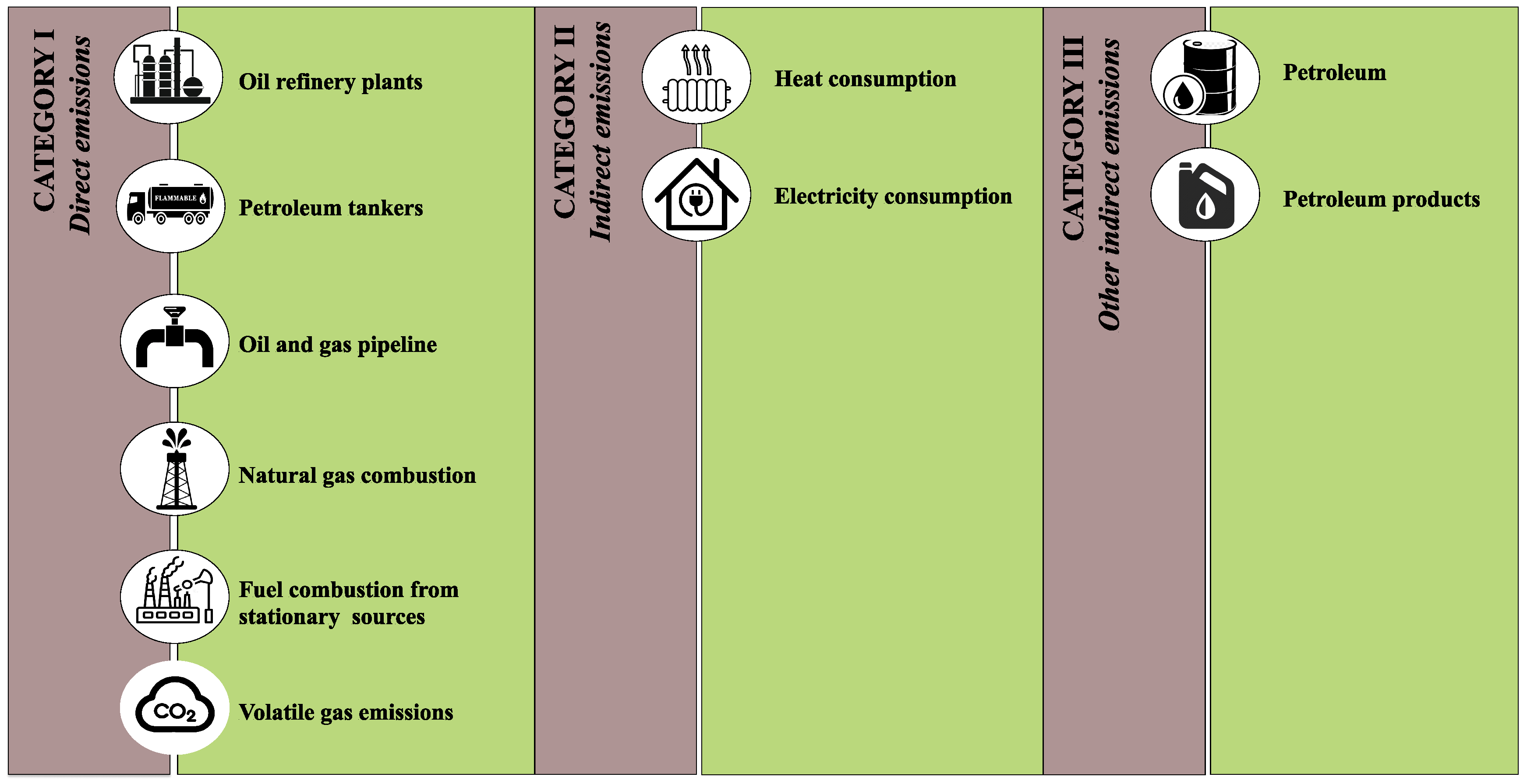
In reality, the ability to show visible decarbonization progress has become one of the most important goals of major petroleum production companies. Major stakeholders frequently fault the petroleum industry for contributing to climate change [44]. However, understanding the types of GHG emissions that the industry generates is important in order to provide a thorough response to this issue. Emissions are typically categorised into three major classes in accordance with international practice (Figure 3) [45].
The first category consists of emissions produced directly by production activities. For the petroleum industry, this category comprises GHG emissions from the extraction, processing, and burning of oil and natural gas as well as from the operation of the company’s energy sources and the provision of heat for its production facilities and operations. The second category consists of indirect GHG emissions from the use of heat and energy sources that the industry purchases for its purposes. The third category, which consists of emissions resulting from the burning of fuels such as oil and gas, are related to the consumption of petroleum goods.
Within the oil and gas sector, the positions of companies vary greatly in terms of their GHG emissions. European companies operate in an environment where GHG emissions management has existed for a long time; for example, in Norway a carbon tax was introduced in 1992 [46,47]. As a result, their activities are relatively low in carbon intensity, and they are more focused on developing the industry and investing in renewable energy and other clean technologies.
The introduction of CCUS technologies as well as the generation and use of hydrogen as fuel are just a few of the deep decarbonization strategies that many oil and gas companies have in place. Hundreds of pertinent initiatives are in various phases of research and development across Europe, the United States, and the Middle East, although up to this point they have solely relied on large state subsidies [48].
The combined capacity of CCUS projects today is only 10 Mt of CO [49,50]; however, under scenarios that are consistent with the goals of the Paris Agreement, by 2050 this amount should be 6 Gt of CO, which exceeds the size of the entire current global oil and gas industry. This creates enormous opportunities for the new industry practices that make use of core oil production competencies [50,51].
3. CO2 Storage Mechanisms in CO2 and CO2 Foam EOR
Injecting CO into a reservoir is a very practical and feasible method of storing carbon, as described in the preceding section. Generally, two or three recovery stages are implemented during the development of an oil field. Oil is produced during primary recovery by natural driving mechanisms backed by the reservoir’s natural energy (dissolved gas expansion, gas cap expansion, saline water influx, etc.) [21]. Oil production rates decrease as reservoir pressure decreases due to the removal of reservoir fluids. Thus, techniques for fluid lifting and pressure maintenance are needed to extend the primary production time. In secondary recovery, a fluid (most frequently water) is injected to push oil to producing wells by maintaining reservoir pressure [52,53].
After secondary recovery, only 30 to 50% of the oil is typically recovered, leaving 50 to 70% of the oil in the reservoir [54]. Because extracting the residual oil requires more sophisticated and expensive technology, reservoirs have traditionally been abandoned at this point. Any method used following secondary recovery is referred to as tertiary recovery [55]. EOR is often considered a tertiary phase of recovery, even though it can be applied at any stage of the development of a petroleum field. For instance, CO injection is considered one of the most promising EOR methods [54]. Due to its low viscosity and density in comparison to the reservoir fluids, CO typically has a significant mobility contrast. This results in unstable displacement in the form of viscous fingering, which adversely impacts oil recovery [40].
Therefore, CO is typically injected along with water that contains surfactant and other additives that can lower the unfavorable mobility of CO in the reservoir. This is known as foam EOR. When gas is mixed with a liquid solution, foam is generated. This strengthens the displacement front and increases the viscosity of the injected fluid, enhancing sweep efficiency and mobility control [56].
Additionally, the relative phase permeability of gas is automatically decreased by the addition of water and gas to generate foam due to an increase in the saturation of mobile water. Due to gravitational segregation, the gas effectively displaces the oil while moving through the top portions of the reservoir [57,58]. As a result, water fills the lower portion of the reservoir in place of the oil, which causes water and gas to move together close to the injection well. Additionally, the capillary effects of foam films considerably restrict gas mobility by confining the gas bubbles and raising their flow resistance. This decrease in gas mobility increases sweep efficiency and leaves more swept zones for CO storage. Thus, rather than propagating in the direction of the production well, additional CO is trapped in the pore spaces [59].
It is important to note that not all of the CO injected is recovered at production wells. Due to capillary forces that immobilize CO mobility within pores, as well as by dissolving in residual oil and water, a significant amount of the CO in the reservoir remains trapped [60]. This volume is referred as CO retention. In CCUS, associated storage refers to the CO that is lost in the formation during the conventional EOR process. The amount of CO that can be stored in this way relies on the characteristics of both the reservoir and the crude oil, as well as operational aspects of oil production such as well spacing, the distance between injection and production wells, and the injection scheme [61].
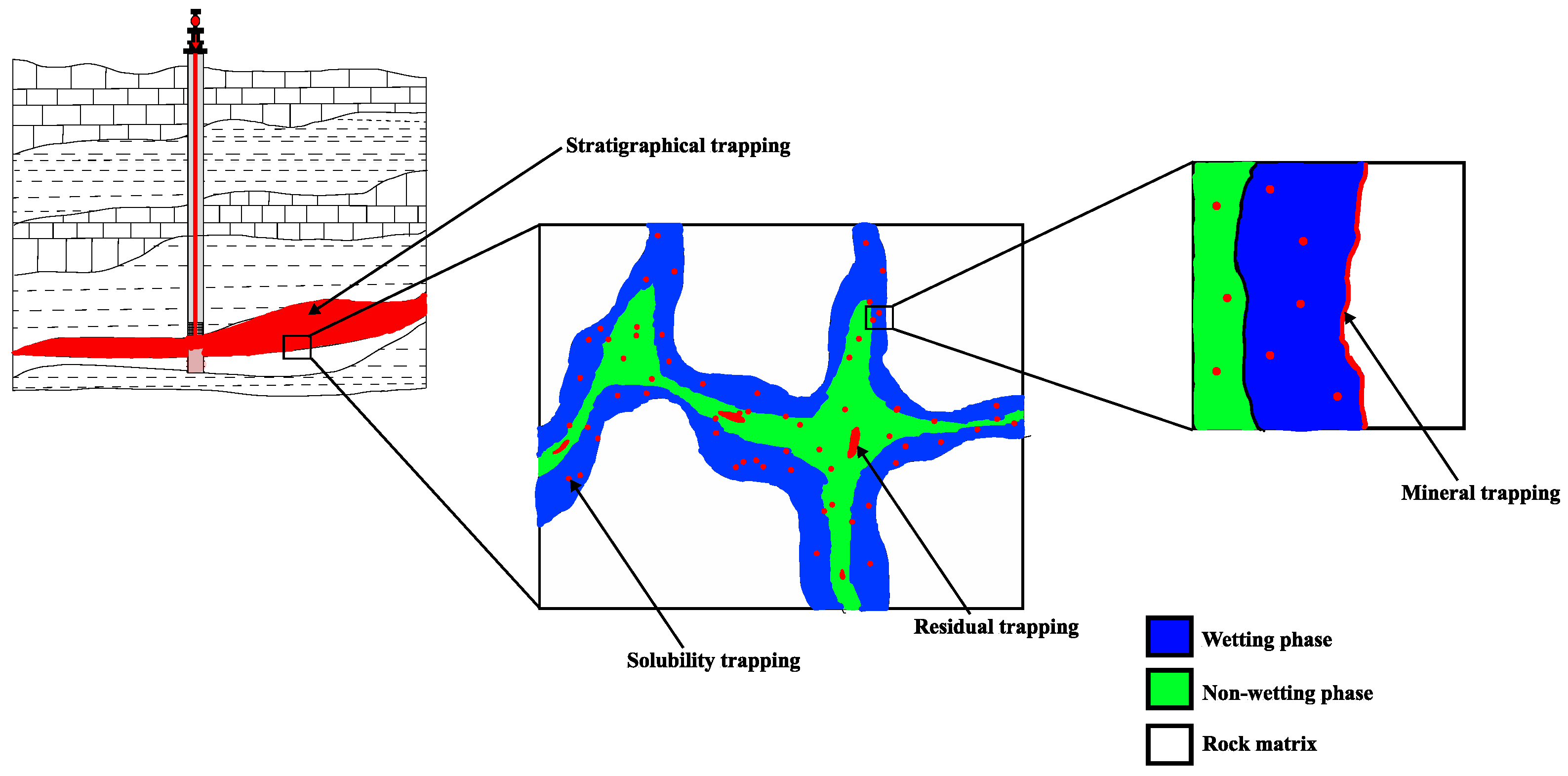
As seen in Figure 4, there are four primary mechanisms for trapping CO in porous material during CO sequestration. These include stratigraphical or structural trapping, residual trapping, solubility trapping, and mineral trapping [62,63,64].
- Structural trapping refers to the confinement of CO as a mobile phase by the field-scale reservoir stratigraphy and structure. CO typically accumulates beneath the impermeable regions of the reservoir, such as caprocks. These tight caprocks serve as a barrier characterized by low permeability. This prevents both buoyancy-induced CO migration upward and percolation across the rock system.
- Residual trapping, is related to structural trapping, as both describe the capillary forces that confine supercritical CO in pores as an immobile phase. Capillary pressures cause CO to be stored as an immobile phase within porous media; this mechanism is significant because it can function without a caprock or stratigraphic seal.
- Solubility trapping refers to the dissolution of CO into reservoir fluids, such as formation water and reservoir oil. This can happen in either the formation water phase or the oil phase, and is dependent on the formation’s pressure, temperature, and salinity.
- The last mechanism is mineral trapping, which is related to solubility trapping, as it depends on CO dissolution into reservoir brine. CO solubility in brine is necessary for mineral trapping. Numerous minerals found in the formation rock become more soluble when CO is dissolved in brine, which lowers the pH of the brine. Therefore, CO interacts both directly and indirectly with the minerals in the formation rock, precipitating secondary carbonate minerals.
The relative importance of the various trapping mechanisms is influenced by the number of factors, including the characteristics and type of the geologic formation and the characteristics of the reservoir fluids [62,65]. Additionally, based on the CO injection approach and settings, the significance of various trapping processes may vary. However, structural and residual trapping account for about 95% of CO storage, making them the most vital mechanisms [66,67,68,69], probably because they heavily rely on the already present capillary forces and tend to balance out the buoyant forces that are directed upward [70].
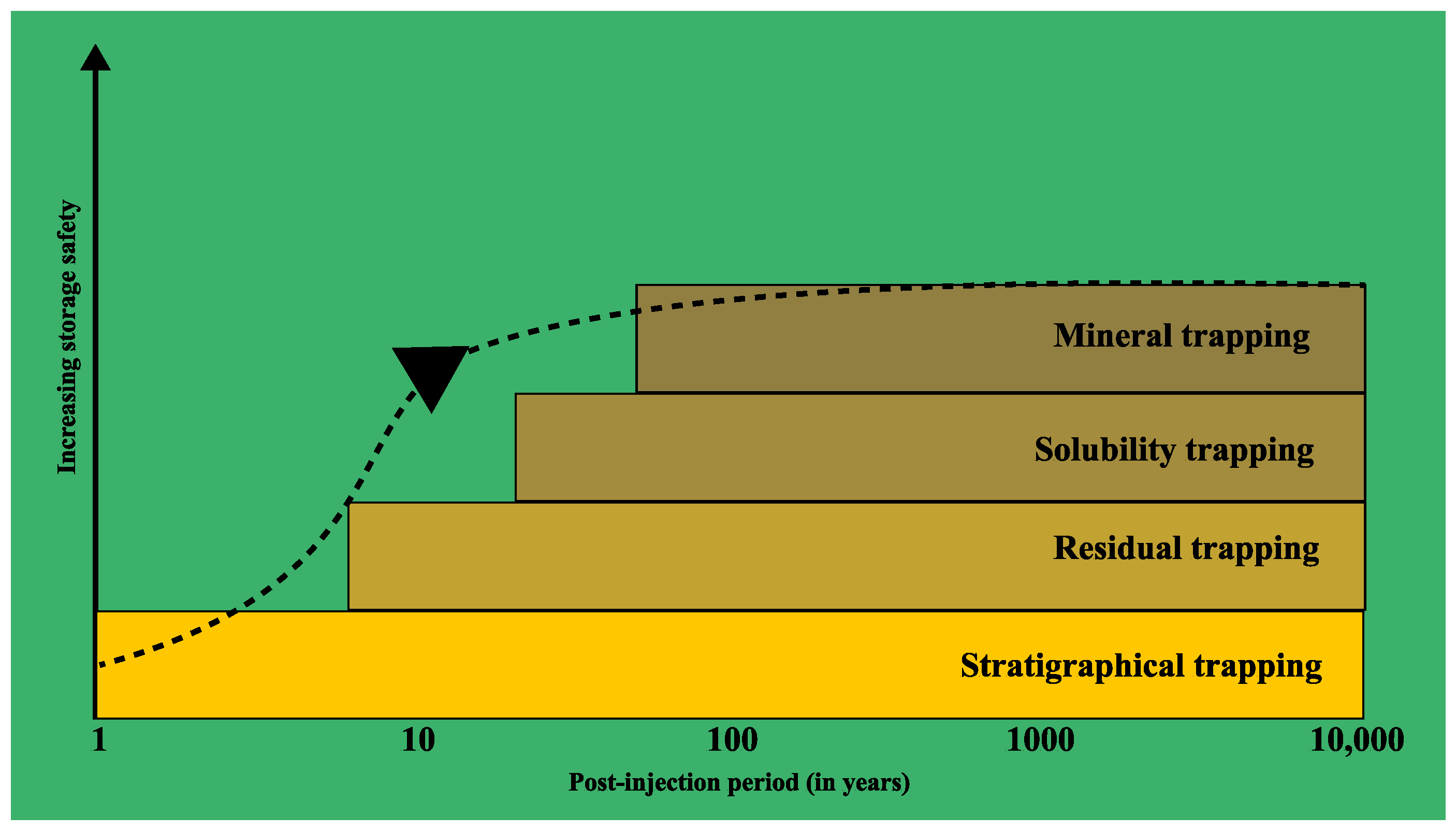
The time scale of the various trapping mechanisms is shown in Figure 5:
The time scale for various trapping techniques in subterranean geological formations is shown in Figure 5. Over time, more secure trapping processes develop following the injection phase, thereby strengthening the long-term safe storage of CO [71,72].
Not all of the residual brine is mobilized, as it may remain trapped during the displacement process. This is mainly because of the significant density and viscosity differences between CO and reservoir brine during the recovery process [73]. CO storage is hampered by these factors, which dominate flow behavior in extremely porous reservoirs. This may limit the amount of CO that can flow through the aquifer’s pore spaces [74]. As a result, while lowering CO mobility is an important task that helps to minimize the aforementioned viscosity and density contrasts, ultimately increasing storage capacity by lowering the amount of residual brine, it is very difficult. In this respect, foams show great potential [63,75].
3.1. Mechanisms of CO2 Sequestration Peculiar to Foams
3.1.1. Gas Trapping by Foam
Gas trapping is one of the most significant microscopic mechanisms involved in foam flow in porous media. A.N. Fried [76] noted that foam movement increases trapped gas saturation. This has subsequently been confirmed by other researchers [77,78,79,80], and it has been revealed that trapped gas saturation in porous media can range from 10–70% when utilizing foam injection. The liquid phase in the foam traps the gas phase during a miscible displacement process using one of the following trapping methods:
- Snap-off is a phenomenon in which the interface between the wetting phase and the non-wetting phase (gas or oil) continues to swell during an imbibation process. This causes the globule to shear thin until it forms a discontinuous phase and becomes trapped in the pores [81].
- Another mechanism is bypassing, in which a non-wetting phase replaces the wetting phase in the small pores or pore throats of an immiscible displacement process [82].
- Finally, the Jamin effect is another phenomenon that occurs when liquid flow in capillaries encounters resistance from gas bubbles or liquid globules caught in pore throats because of the differential capillary pressure across the bubble or globule [83].
These trapping mechanisms can occur during foam flow in porous media due to the fact that foams possess properties that make them conducive for gas trapping [84]. First, foams are made up of variously sized gas bubbles that are sparged throughout a continuous liquid phase. Second, the wetting phase fills the small pores, leaving no room for gas bubbles in the non-wetting phase, meaning that they occupy the middle of the large pores. Third, bubbles can have sizes as large as the pores where they are generated, and can migrate from a large pore before becoming trapped in a smaller pore [85].
Foam traps and holds CO bubbles within the swept area [62,79]. Additionally, a portion of the gas dissolves into the residual formation water, and over time may interact with the formation salts and minerals to remain in the form of minerals. Compared to a gas–liquid flow without foam, residual CO saturation in foam is significantly higher [86].
In the works of Gong et al. [87,88], it was found that even in the region of “collapsed foam” created during gas injection very near the well, much gas is retained upon subsequent imbibition of surfactant solution or water, including a gas saturation greater than 50% in corefloods. In the portion of the core corresponding to the formation beyond the immediate vicinity of the wellbore, where the foam has not yet collapsed, residual saturation can be greater than 70%. Thus, foam increases both the sweep efficiency and the saturation of gas trapped by capillary forces within the region.
3.1.2. Reduction of Gravitational Segregation
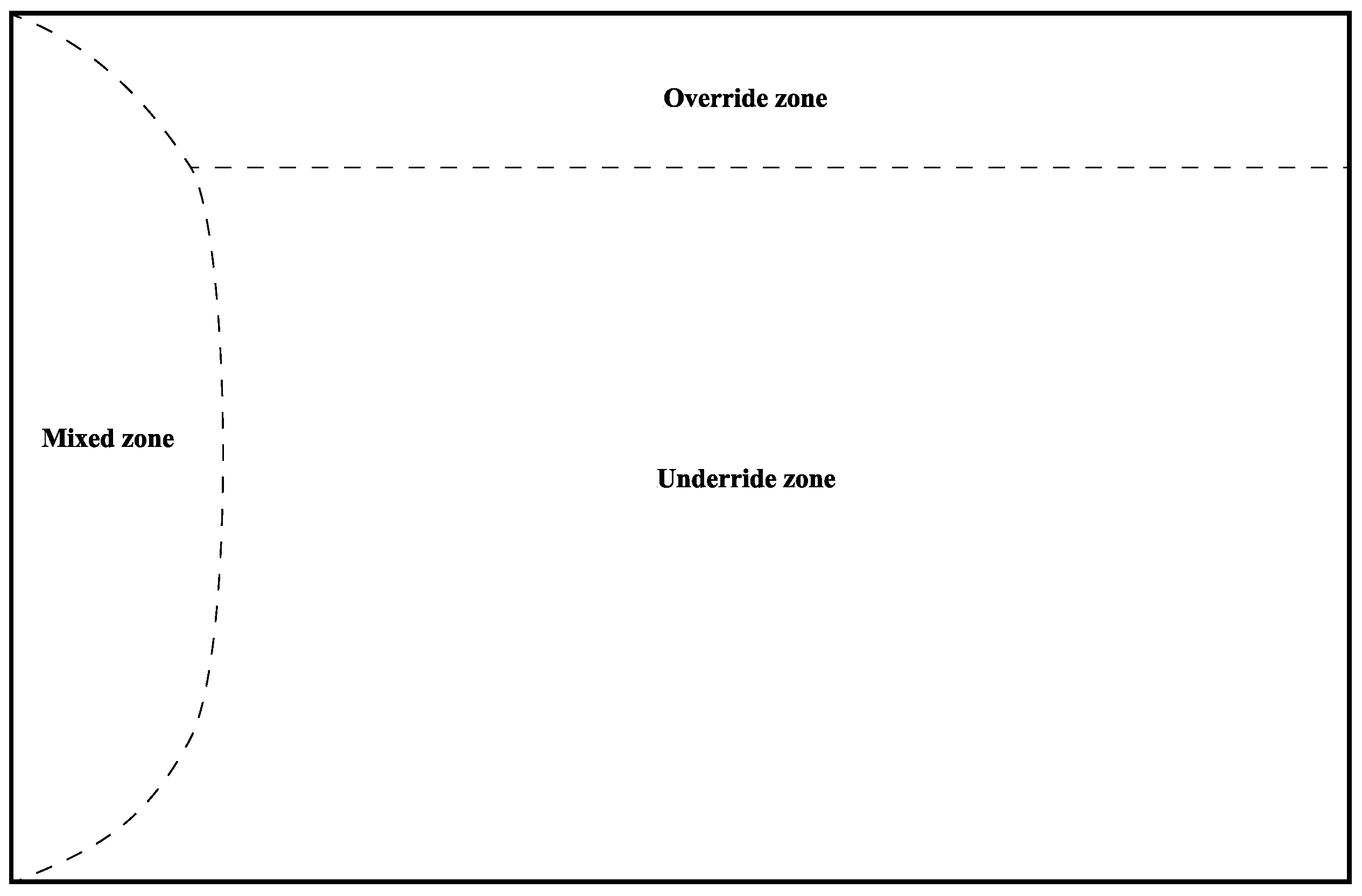
Al-Ayesh et al. [89] and Kapetas et al. [90] highlighted the CO storage mechanism of foam by enhancing the injection profile in terms of gravitational segregation. Foam can redirect the flow towards the less permeable layers in the bottom zone of the reservoir, as shown in Figure 6 for a geological formation with highly permeable layers in the upper zone. CO is able to spread further after being injected into these zones before reaching the higher zone. This indicates that more reservoir volume is swept, trapping more CO. Thus, foam provides yet another benefit by reducing the effects of gravity override in heterogeneous formations [91].
In a laboratory core flood experiment, Tanzil et al. [92] revealed that a capillary effect prevented gas from flowing across the boundary from a low-permeability zone to a high-permeability one. Due to the presence of a surfactant in the liquid phase, the foam was generated as the gas passed through the barrier. As a result, gas can remain at the interface and regenerate or collapse; alternatively, it may propagate as foam. In either case, there is a decrease in both vertical permeability and upward movement of the gas [91,93].
3.1.3. Blockage of CO2 Leakage
According to several studies [94,95], foam may help to mitigate CO storage reservoir leaks. Keeping CO safely underground is the major objective of storage in geological formations. In essence, CO is stored in caprock-covered geological formations such as saline aquifers, depleted reservoirs, and other geological formations [96]. While the caprock is relatively impermeable, these reservoirs often have significantly high porosities and permeabilities. While this condition is fairly ideal for the long-term storage of CO, there is a chance that in specific circumstances CO could undesirably migrate out of porous media through two distinct pathways [94,97]. These two pathways are outlined below in Figure 7.
Geological leakage involves naturally occurring fractures, whereas engineering leakage pathways are those caused by wellbore cementing failure or through fractures induced by engineering operations [98].
Because foams are used for CO mobility control, they are well equipped to reduce or eliminate the leakage of stored CO. The following explanations describe how foams reduce CO leakage in porous media.
First, the apparent viscosity of CO increases as a result of the coalescing fluidity of the foam, allowing the extra driving pressure difference to easily displace the bubbles [40]. Additionally, the spread of the surfactant can cause a gradient in the surface tension, lessening bubble movement. Finally, by redistributing the interactions between gravity and viscous forces the foam is able to lessen the impact of gravitational segregation.
In these ways, foam can decrease CO leakage, improving the ability of porous media to effectively store CO. These claims are supported by previous studies [99,100,101] in which it has been observed that in situ generation of foam reduces CO leakage and decreases the mobility of free CO due to increased viscosity and enhanced resistance to gas flow.
4. Determination of CO2 Storage Efficiency and Co-Optimization with EOR
The term “CO storage efficiency” is crucial to this review, as it indicates how much CO can be stored in a reservoir. It can be used to evaluate how the process or the used chemicals are effective. Generally, it is the volume fraction of the pore space for CO storage. It has several components that reflect the different physical barriers that mitigate CO contact with the reservoir pore volume [102]. However, the determination of this parameter is not as simple as it appears. It stems from several variables, including the formation’s heterogeneity, the injection scheme and mode, other formation properties, transport processes, and other factors that can affect how efficiently CO is stored. Additionally, different CO storage mechanisms may take place at different stages depending on the thermodynamic conditions under which CO is injected [103,104]. As a result, different studies have used a range of approaches, which makes it challenging to compare and assess them. In this section, we cover three recently developed and frequently applied functions for estimating CO storage efficiency and propose an improvement to these functions.
According to Kovscek et al. [104], CO storage efficiency is the ratio of the volume of stored CO to the reservoir’s total pore volume (Equation (1)). However, this method does not account for the geological limitations of the reservoir or consider that the total pore volume in the reservoir may not be available for CO storage. Furthermore, this function assumes that CO has the same volume even when thermobaric conditions change, which is not possible. In fact, as the temperature and pressure in the reservoir change, the volume and phase of CO change as well [105].
Thus, Jahangiri et al. [106] modified this function and proposed that CO storage efficiency be defined as the ratio of CO stored in the reservoir to the total CO storage capacity of the reservoir (Equation (2)). Although this might be true for theoretical definitions, the total amount of CO storage capacity in the reservoir is an unclear factor in analytical terms [103]. This is because CO storage capacity in geological formations exists on four different levels, and the calculations for each of these storage capacity levels are different [107,108,109].
Due to this, Kamali et al. [110] continued to work on this function, and claimed that the ratio of stored CO to CO injected in the reservoir can be used to determine the CO storage efficiency (Equation (3)). However, this function only represents the injected CO utilization factor, not the reservoir’s storage capacity [105]. Additionally, operating companies usually account for CO loss from production or injecting wells, which is not taken into consideration in this function [111,112].
Due to the shortcomings of earlier research, in this work we suggest a modified function for CO storage efficiency. The CO storage factor can be calculated as the ratio of the reservoir’s theoretical CO storage capacity to the cumulative amount of CO that is injected, produced, and lost (Equation (4)).
Because CO loss mostly consists of surface and subsurface losses, there are neither exact statistics nor a known method by which it can be computed. When a power outage occurs, or when pipes need to be repaired, a portion of CO is lost to surface loss, while subsurface loss might happen when CO migrates laterally outside of the production well [112]. According to industry experience, the recommended figure for CO loss is 5% of the cumulative injected CO.
The purpose of injecting CO into the reservoir in various ways, as indicated in earlier sections, is not only for CO storage; it can aid in oil recovery as well. Therefore, it is essential to co-optimize CO storage and oil production. In order to co-optimize both functions, the aforementioned proposed function can be paired with a recovery factor parameter and the addition of weighting variables.
Here, and are weighting factors and maximally equal 0.5, which demonstrates that CO and oil recovery have the same priority. Although each weighting element can be altered depending on the operation’s objective, their combined value must be 1.
Levels of CO2 Storage Capacity
The most pertinent and important concept is theoretical storage capacity, which relates to the actual constraint on the quantity of CO that can be stored by the porous medium [107]. It is built on the assumption that the full geometric space of the produced oil can be utilized for CO storage, and is based on the material balance equation. This means that CO can fill the swept zones left behind by the produced oil, and can dissolve into crude oil and/or water during injection [109].
where = theoretical CO storage capacity in the porous medium, kg; = the density of CO in reservoir conditions, kg/m; RF = the recovery factor; A = the cross-sectional area of the porous medium, m; h = reservoir thickness, m; = porosity; = the volume of injected water, m; = the volume of produced water, m; = irreducible water saturation; = the solubility coefficient of CO in formation water; and = the solubility coefficient of CO in oil.
Effective storage capacity, on the other hand, takes into account the numerous properties of the geological formation, including pressure and pore volume. It is a part of the theoretical storage capacity. It is usually influenced by the mobility of the injectant, gravitational separation, and reservoir heterogeneity. Thus, it cannot be more than the theoretical storage capacity [63,108].
Therefore, multiple calculation methods can be utilized for estimating CO storage capacity based on the objectives of the evaluation and storage mechanisms [107]. The key is to ascertain the theoretical and effective storage capacity, as the matched and practical storage capacities are rarely used in practice.
5. Experimental and Numerical Studies of CO2 Foam for CO2 Storage
The viscosity of CO can be 10 to 50 times lower than that of reservoir oil under typical reservoir conditions, placing the gas at significant risk of channeling through the oil and preferentially flowing through the more permeable zones [56,58]. Surfactants can be added to a liquid solution and injected simultaneously or successively with CO to reduce this effect [113]. The mixture produces foam, which is more viscous than either the liquid or gas. As a result, the flow is diverted from the highly permeable areas, and can flow towards the unswept low-permeability zones [114].
Furthermore, the propagation front becomes more uniform, as opposed to the fingering scenario with just CO, which enhances oil recovery and makes more reservoir space available for CO storage [40,115]. CO foams themselves are ideally classified as a non-toxic carbon sequestration technique that can greatly lower industrial greenhouse gas emissions. This satisfies the requirements set forth by the US Environmental Protection Agency for a procedure to be termed as green chemistry [116].
The effect of foam on CO storage capacity during foam flooding was investigated in Foyen et al. [117]. In order to study foam generation, propagation, and coalescence, the authors of this study injected dense CO into surfactant-saturated sandstone cores. In their work, CO storage capacity was assessed as the fraction of the pore volume that was accessible for storing CO. Their results showed that the CO storage capacity of the sandstone core increased by 27% when foam was generated, as compared to the baseline CO injection without foam. The authors attributed this to reduced water–CO interfacial tension, which in turn reduced residual water saturation and improved microscopic and volumetric sweeps. As such, the results of this study imply increased storage capacity for the sequestered CO.
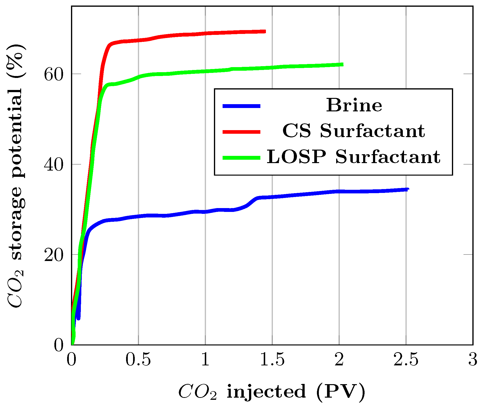
This argument was further supported in the work of Yu et al. [118], in which the storage potential of CO in Berea sandstones was evaluated. CO foams were generated with Amphosol CS-50 and Ammonyx LO SPECIAL surfactants, then compared with the injection of CO alone. The results are shown in Figure 8.
It can be seen that there is an early breakthrough of CO during CO injection after about 0.11 injected pore volumes. However, the breakthrough was not noticeable when using Amphosol and Ammonyx before 0.28 and 0.24 PV, respectively. Furthermore, the CO storage potentials were 69.4% and 62.1%, which are significantly higher than 34.3% for CO flooding without a surfactant. The authors noted that the presence of the surfactants greatly aided in controlling the propagation front, resulting in a 200% increase in the amount of original water that was displaced. The authors attributed this to a significant reduction in CO mobility.
Implementing CO foam in field conditions is challenging due to the complicated physics involved; foam strength under reservoir conditions plays a vital role in determining its sequestration performance. To address these problems, in Iskandar et al. [119] the authors developed machine learning models that could precisely predict apparent viscosity for both bulk phase and sandstone formations. The authors used these models to compute foam quality under various conditions and determine the apparent viscosity, with the aim of effectively reducing gas mobility while simultaneously improving EOR and sequestration processes. The results in Viktoonkijvanich et al. [120] further support these arguments; there, the authors investigated CO storage in aquifers while co-injecting CO with surfactants to generate foam. According to the authors, alternating injections of CO and surfactant solutions at 0.85 fractional flow resulted in the best performance when there was no seal, while simultaneous injection at 0.5 fractional flow produced the best results when a reliable trapping mechanism was present.
Furthermore, in Lyu et al. [121], the complex phase behavior of an aquifer fluid system was precisely described using the Peng–Robinson equation of state (PR EOS) and an activity model. When the capillary transition zone was absent, the simulation results showed good agreement with analytical answers. According to the authors, injected foam successfully restricted gas mobility by trapping bubbles and preventing upward migration caused by gravity, which increased sweep efficiency and freed up more space for CO storage. Furthermore, their results indicated that dissolution trapping mechanisms may not be important in the long term, as residual foam trapping becomes more efficient with time, potentially suggesting new methods of efficient carbon sequestration.
Other studies on the application of foam for CO storage are summarized in Table 1.
6. Enhancing Foam for CO2 Storage
In order to implement foam injection as a reliable and favorable green technology, more research and efforts are needed to address the advancement and improvement of CO capture and storage technology. On the laboratory scale, the CO storage efficiency of foams can be improved using CO-soluble surfactants and introducing nanoparticles to the liquid phase.
- The use of CO-philic soluble surfactants in the generation of CO foam can guarantee the accessibility of surfactant for foam generation wherever CO flows in the reservoir [117,130]. Due to the significant volumes of brine already present in oil-bearing formations, the ability to inject a CO-based surfactant solution might lessen the need for alternating injections of brine. An SAG process in which surfactant is present in the aqueous phase may be possible by the identification of CO-soluble surfactants, increasing the likelihood of in situ foam generation [131,132]. CO-soluble surfactants provide better film stabilization ability than conventional aqueous surfactants. This ensures faster propagation in porous media, increasing the pressure drop and boosting sweep efficiency. Several commercially available non-ionic hydrocarbon-based surfactants that are soluble in water have shown sufficient solubility in CO [133,134]. Examples include fatty acid-based surfactants, alkylphenol, and styryl phenol surfactants.
- Nanoparticles can be used to increase foam stability, subsequently increasing its ability to store CO. The intense adsorption at the liquid surface caused by the high adhesion energy of solid nanoparticles allows for the generation of a strong and stable foam [135,136]. Nanoparticles are excellent for CO foam generation, as an emulsion can be created without first solubilizing them with CO. A water phase without solid particles can pass through without destabilizing the foam, as the particles that are adsorbed at the foam interface do not easily desorb [137]. Surfactant molecules frequently enter and exit the liquid interface, providing only short term stabilization. However, because nanoparticles have hydrophilic properties they can exist primarily in the liquid phase. In addition, the small size of nanoparticles allows them to travel far from the injector without experiencing considerable particle retention or loss [138].
7. Conclusions and Future Research
This work has reviewed the possible advantages of using CO foams in the context of carbon storage. Their use can ensure that the carbon footprint of the oil production process is reduced while continuing to supply the world with secure energy. However, optimizing foam systems necessitates a thorough comprehension of every component involved in foam flow in porous media. Therefore, in subsequent experimental works, more focus should be placed on the stability and performance of CO foams. Furthermore, the synergistic interactions that result from combining nanoparticles with surfactants as foaming agents could potentially be an economical method of generating high-performing and field-specific foam systems. The following conclusions can be drawn from this review:
- A co-optimization function was developed that takes into account CO loss during actual operation and combines oil recovery with CO storage.
- The amount of CO stored by the solubility trapping mechanism, which is regarded as one of the primary CO storage processes in oil reservoirs, is directly influenced by the solubility of CO in residual oil and formation water.
- Because CO dissolution causes oil to swell, viscosity to decrease, and interfacial tension to decrease, it is one of the key mechanisms that contributes to the significant potential for improving CO storage. As a result, the effectiveness of any CO-CCUS project largely depends on how soluble CO is in oil under reservoir conditions.
- Because the injection of CO increases pressure, it has the ability to propagate upwards; if fractures exist, CO leakage can occur. Thus, the risk of CO leakage from storage sites represents a significant challenge. Additional study is required in order to better comprehend the geological mobility of CO gas released by foam after it has coalesced, as well as the interactions of foam with geomaterials, minerals, and ground chemicals.
- It is crucial that the CO trapped in a reservoir by capillary forces stays there forever, or at least for a very long time. The surfactant or related reagents may degrade chemically or thermally while stored, and may even be displaced outside the swept zone. Thus, investigating their long-term stability under reservoir conditions is very important to CO storage.
- The use of CO foam for sequestration necessitates the extensive injection of surfactants into the ground. This raises questions around their environmental safety. Therefore, it is crucial to conduct in-depth research on the environmental effects of potential leakage of foaming agents and their additives.
- It is imperative to design less harmful surfactant systems and foaming additives, taking into account the possibility of their degradation in reservoir conditions. Thus, our ongoing research is focused on the use of binary surfactants to improve the stability of foams under harsh reservoir conditions where the use of surfactants in their single forms has led to foam instability in these conditions.
- The efficiency of oil recovery and CO storage in tight oil reservoirs should be a future focus in light of the global development of unconventional reservoirs. Future research in this area might be concentrated on investigating the effects of various foam injection techniques on simultaneous EOR and sequestration in core samples with extremely low permeability. Additionally, it is important to analyze the effects of natural and artificial fractures in the matrix on the effectiveness of co-optimizing EOR and CO storage in unconventional formations.
- In addition to enhancing foam stability, recent studies have proposed adding nanoparticles to aqueous foaming solutions in order to improve the CO sequestration process and increase the ability of CO to be absorbed in the liquid phase. Thus, it is imperative to look into how nanoparticles can be formulated in foams to increase both residual oil displacement and sequestration, as well as their role in lowering CO emissions.
- Mineralization trapping is a significant mechanism of CO storage. It aims to safely sequester CO over the long term. However, it is challenging to implement in a lab setting due to the time constraints. Therefore, future work should be directed towards developing numerical models that can simulate the concurrent processes of CO storage. For the purpose of understanding the impact and contribution of the mineralization trapping mechanism and how it influences EOR, these models should have interfaces that can adequately simulate all of the aqueous reactions occurring in the formation.
Author Contributions
All authors contributed equally to this work. All authors have read and agreed to the published version of the manuscript.
Funding
This work was supported by the Ministry of Science and Higher Education of the Russian Federation under agreement No. 075-10-2022-011 within the framework of the development program for a world-class research center.
Data Availability Statement
Not applicable.
Conflicts of Interest
The authors declare no conflict of interest.
References
- Castellanos Diaz, O.; Katiyar, A.; Hassanzadeh, A.; Crosley, M.; Knight, T.; Rozowski, P. Evaluation of carbon footprint for a hydrocarbon foam EOR field pilot. In Proceedings of the SPE Improved Oil Recovery Conference, Virtual, 25–29 April 2022. [Google Scholar]
- Pandey, A.; Sinha, A.S.K.; Chaturvedi, K.R.; Sharma, T. Experimental investigation on effect of reservoir conditions on stability and rheology of carbon dioxide foams of nonionic surfactant and polymer: Implications of carbon geo-storage. Energy 2021, 235, 121445. [Google Scholar]
- Zou, C.; Xue, H.; Xiong, B.; Zhang, G.; Pan, S.; Jia, C.; Wang, Y.; Ma, F.; Sun, Q.; Guan, C.; et al. Connotation, innovation and vision of “carbon neutrality”. Nat. Gas Ind. B 2021, 8, 523–537. [Google Scholar] [CrossRef]
- Liu, Q.; Wu, X.; Wang, X.; Jin, Z.; Zhu, D.; Meng, Q.; Huang, S.; Liu, J.; Fu, Q. Carbon and hydrogen isotopes of methane, ethane, and propane: A review of genetic identification of natural gas. Earth Sci. Rev. 2019, 190, 247–272. [Google Scholar] [CrossRef]
- Peters, G.P.; Andrew, R.M.; Canadell, J.G.; Friedlingstein, P.; Jackson, R.B.; Korsbakken, J.I.; Le Quéré, C.; Peregon, A. Carbon dioxide emissions continue to grow amidst slowly emerging climate policies. Nat. Clim. Chang. 2020, 10, 3–6. [Google Scholar] [CrossRef]
- Dmitrienko, M.A.; Nyashina, G.S.; Strizhak, P.A. Major gas emissions from combustion of slurry fuels based on coal, coal waste, and coal derivatives. J. Clean. Prod. 2018, 177, 284–301. [Google Scholar] [CrossRef]
- Hockstad, L.; Hanel, L. Inventory of U.S. Greenhouse Gas Emissions and Sinks; U.S. Department of Energy Office of Scientific and Technical Information: Oak Ridge, TN, USA, 2018.
- Aleem, A.; Masood, H.; Khan, S.U. Carbon Footprint Estimation for an Oil and Gas Industry. Int. J. Eng. Work. 2021, 8, 98–102. [Google Scholar] [CrossRef]
- Chew, Z.T.; Hoy, Z.X.; Woon, K.S.; Liew, P.Y. Integrating greenhouse gas reduction and waste policy targets to identify optimal waste treatment configurations via Carbon Emission Pinch Analysis. Process. Saf. Environ. Prot. 2022, 160, 661–675. [Google Scholar] [CrossRef]
- Yousef, Z.Y.; Kokal, S.K. The synergistic effect of surfactant and polymer in stabilizing CO2-foams. In Proceedings of the Second EAGE Workshop on Geochemistry in Petroleum Operations and Production, Muscat, Oman, 1–4 October 2018; European Association of Geoscientists & Engineers: Utrecht, The Netherlands, 2018. [Google Scholar]
- IEA. Global Energy Review: CO2 Emissions in 2021; Technical Report; IEA: Paris, France, 2022. [Google Scholar]
- Yang, X.; Khan, I. Dynamics among economic growth, urbanization, and environmental sustainability in IEA countries: The role of industry value-added. Environ. Sci. Pollut. Res. Int. 2022, 29, 4116–4127. [Google Scholar] [CrossRef]
- Khan, I.; Hou, F.; Zakari, A.; Tawiah, V.K. The dynamic links among energy transitions, energy consumption, and sustainable economic growth: A novel framework for IEA countries. Energy 2021, 222, 119935. [Google Scholar] [CrossRef]
- Zhu, Z.; Liao, H.; Liu, L. The role of public energy R&D in energy conservation and transition: Experiences from IEA countries. Renew. Sustain. Energy Rev. 2021, 143, 110978. [Google Scholar]
- Hedman, Å.; Rehman, H.U.; Gabaldón, A.; Bisello, A.; Albert-Seifried, V.; Zhang, X.; Guarino, F.; Grynning, S.; Eicker, U.; Neumann, H.M.; et al. IEA EBC Annex83 Positive Energy Districts. Buildings 2021, 11, 130. [Google Scholar] [CrossRef]
- Addassi, M.; Omar, A.; Hoteit, H.; Afifi, A.M.; Arkadakskiy, S.; Ahmed, Z.T.; Kunnummal, N.; Gislason, S.R.; Oelkers, E.H. Assessing the potential of solubility trapping in unconfined aquifers for subsurface carbon storage. Sci. Rep. 2022, 12, 20452. [Google Scholar] [CrossRef] [PubMed]
- Plante, E.C.L.; Simonetti, D.A.; Wang, J.; Al-Turki, A.; Chen, X.; Jassby, D.; Sant, G.N. Saline Water-Based Mineralization Pathway for Gigatonne-Scale CO2 Management. ACS Sustain. Chem. Eng. 2021, 9, 1073–1089. [Google Scholar] [CrossRef]
- Bui, M.; Adjiman, C.S.; Bardow, A.; Anthony, E.J.; Boston, A.; Brown, S.; Fennell, P.S.; Fuss, S.; Galindo, A.; Hackett, L.A.; et al. Carbon capture and storage (CCS): The way forward. Energy Environ. Sci. 2018, 11, 1062–1176. [Google Scholar]
- Jones, S.A.; Kahrobaei, S.; van Wageningen, N.; Farajzadeh, R. CO2 foam behavior in carbonate rock: Effect of surfactant type and concentration. Ind. Eng. Chem. Res. 2022, 61, 11977–11987. [Google Scholar] [CrossRef]
- Paraschiv, S.; Paraschiv, L.S. Trends of carbon dioxide (CO2) emissions from fossil fuels combustion (coal, gas and oil) in the EU member states from 1960 to 2018. Energy Rep. 2020, 6, 237–242. [Google Scholar] [CrossRef]
- Farajzadeh, R.; Eftekhari, A.; Dafnomilis, G.; Lake, L.; Bruining, J. On the sustainability of CO2 storage through CO2–Enhanced oil recovery. Appl. Energy 2020, 261, 114467. [Google Scholar] [CrossRef]
- Adu, E.; Zhang, Y.; Liu, D. Current situation of carbon dioxide capture, storage, and enhanced oil recovery in the oil and gas industry. Can. J. Chem. Eng. 2019, 97, 1048–1076. [Google Scholar] [CrossRef]
- Vásquez Haro, H.A.; Gomes, M.S.d.P.; Rodrigues, L.G. Numerical analysis of carbon dioxide injection into a high permeability layer for CO2-EOR projects. J. Pet. Sci. Eng. 2018, 171, 164–174. [Google Scholar] [CrossRef]
- Zhang, C.; Wu, S.; Li, Z.; Zhao, D.; Lv, G. Improved co-optimal and evaluable index of carbon sequestration and enhanced oil recovery. Simulation 2021, 97, 145–154. [Google Scholar] [CrossRef]
- Shannak, S.; Malov, A. Could China meet its emission reduction goal by CO2-EOR. J. Sci. Technol. Policy Manag. 2021, 12, 24–40. [Google Scholar] [CrossRef]
- Liu, Y.; Rui, Z. A storage-driven CO2 EOR for a net-zero emission target. Engineering 2022, 18, 79–87. [Google Scholar] [CrossRef]
- Cho, J.; Jeong, M.S.; Lee, Y.W.; Lee, H.S.; Lee, K.S. Techno-economic analysis of intermediate hydrocarbon injection on coupled CO2 storage and enhanced oil recovery. Energy Explor. Exploit. 2021, 39, 1532–1550. [Google Scholar] [CrossRef]
- Chen, B.; Pawar, R. Joint optimization of well completions and controls for CO2 enhanced oil recovery and storage. In Proceedings of the SPE Improved Oil Recovery Conference. Society of Petroleum Engineers, Virtual, 31 August–4 September 2020. [Google Scholar]
- Al-Shargabi, M.; Davoodi, S.; Wood, D.A.; Rukavishnikov, V.S.; Minaev, K.M. Carbon dioxide applications for enhanced oil recovery assisted by nanoparticles: Recent developments. ACS Omega 2022, 7, 9984–9994. [Google Scholar] [CrossRef] [PubMed]
- Guo, H.; Lyu, X.; Meng, E.; Xu, Y.; Zhang, M.; Fu, H.; Zhang, Y.; Song, K. CCUS in China: Challenges and Opportunities. In Proceedings of the SPE Improved Oil Recovery Conference, Virtual, 25–29 April 2022. [Google Scholar]
- Núñez-López, V.; Gil-Egui, R.; Hosseini, S. Environmental and operational performance of CO2-EOR as a CCUS technology: A Cranfield example with dynamic LCA considerations. Energies 2019, 12, 448. [Google Scholar] [CrossRef] [Green Version]
- Kashkooli, S.B.; Gandomkar, A.; Riazi, M.; Tavallali, M.S. The investigation of gas trapping and relative permeability alteration during optimization of CO2-EOR and sequestration. Int. J. Greenh. Gas Control 2022, 113, 103529. [Google Scholar] [CrossRef]
- Adel, I.A.; Tovar, F.D.; Zhang, F.; Schechter, D.S. The impact of MMP on recovery factor during CO2—EOR in unconventional liquid reservoirs. In Proceedings of the SPE Annual Technical Conference and Exhibition, Dallas, TX, USA, 24–26 September 2018. [Google Scholar]
- Jia, B.; Tsau, J.S.; Barati, R. A review of the current progress of CO2 injection EOR and carbon storage in shale oil reservoirs. Fuel 2019, 236, 404–427. [Google Scholar] [CrossRef]
- Arnaut, M.; Vulin, D.; José García Lamberg, G.; Jukić, L. Simulation analysis of CO2-EOR process and feasibility of CO2 storage during EOR. Energies 2021, 14, 1154. [Google Scholar] [CrossRef]
- Li, D.; Saraji, S.; Jiao, Z.; Zhang, Y. CO2 injection strategies for enhanced oil recovery and geological sequestration in a tight reservoir: An experimental study. Fuel 2021, 284, 119013. [Google Scholar] [CrossRef]
- Wang, L.; He, Y.; Wang, Q.; Liu, M.; Jin, X. Multiphase flow characteristics and EOR mechanism of immiscible CO2 water-alternating-gas injection after continuous CO2 injection: A micro-scale visual investigation. Fuel 2020, 282, 118689. [Google Scholar] [CrossRef]
- Iino, A.; Onishi, T.; Datta-Gupta, A. Optimizing CO2- and field-gas-injection EOR in unconventional reservoirs using the fast-marching method. SPE Reserv. Eval. Eng. 2019, 23, 261–281. [Google Scholar] [CrossRef]
- Wu, Q.; Ding, L.; Zhang, L.; Ge, J.; Rahman, M.A.; Economou, I.G.; Guérillot, D. Polymer enhanced foam for improving oil recovery in oil-wet carbonate reservoirs: A proof of concept and insights into the polymer-surfactant interactions. Energy 2023, 264, 126256. [Google Scholar] [CrossRef]
- Bello, A.; Ivanova, A.; Cheremisin, A. Enhancing N2 and CO2 foam stability by surfactants and nanoparticles at high temperature and various salinities. J. Pet. Sci. Eng. 2022, 215, 110720. [Google Scholar] [CrossRef]
- Zhang, X.; Zheng, W.; Zhang, T.; Ge, J.; Jiang, P.; Zhang, G. CO2 in water foam stabilized with CO2-dissolved surfactant at high pressure and high temperature. J. Pet. Sci. Eng. 2019, 178, 930–936. [Google Scholar] [CrossRef]
- Griffiths, S.; Sovacool, B.K.; Kim, J.; Bazilian, M.; Uratani, J.M. Decarbonizing the oil refining industry: A systematic review of sociotechnical systems, technological innovations, and policy options. Energy Res. Soc. Sci. 2022, 89, 102542. [Google Scholar]
- Abbasi, T.; Abbasi, S.A. Decarbonization of fossil fuels as a strategy to control global warming. Renew. Sustain. Energy Rev. 2011, 15, 1828–1834. [Google Scholar] [CrossRef]
- Matsumoto, R.; Tabata, T. Impact and challenges of reducing petroleum consumption for decarbonization. Appl. Sci. 2022, 12, 3738. [Google Scholar] [CrossRef]
- Bernoville, T. What Are Scopes 1, 2 and 3 of Carbon Emissions? Available online: https://plana.earth/academy/what-are-scope-1-2-3-emissions (accessed on 12 June 2022).
- Lau, H.C.; Ramakrishna, S.; Zhang, K.; Radhamani, A.V. The role of carbon capture and storage in the energy transition. Energy Fuels 2021, 35, 7364–7386. [Google Scholar] [CrossRef]
- Gizzatov, A.; Pierobon, S.; AlYousef, Z.; Jian, G.; Fan, X.; Abedini, A.; Abdel-Fattah, A.I. High-temperature high-pressure microfluidic system for rapid screening of supercritical CO2 foaming agents. Sci. Rep. 2021, 11, 3360. [Google Scholar] [CrossRef]
- Byrum, Z.; Pilorgé, H.; Wilcox, J. Technological Pathways for Decarbonizing Petroleum Refining; World Resources Institute: Washington, DC, USA, 2021. [Google Scholar]
- Greig, C.; Uden, S. The value of CCUS in transitions to net-zero emissions. Electr. J. 2021, 34, 107004. [Google Scholar] [CrossRef]
- Sun, L.; Dou, H.; Li, Z.; Hu, Y.; Hao, X. Assessment of CO2 storage potential and carbon capture, utilization and storage prospect in China. J. Energy Inst. 2018, 91, 970–977. [Google Scholar] [CrossRef]
- Bazhenov, S.; Chuboksarov, V.; Maximov, A.; Zhdaneev, O. Technical and economic prospects of CCUS projects in Russia. Sustain. Mater. Technol. 2022, 33, e00452. [Google Scholar]
- Emrani, A.S.; Nasr-El-Din, H.A. Stabilizing CO2 foam by use of nanoparticles. SPE J. 2017, 22, 494–504. [Google Scholar] [CrossRef]
- Kil, R.A.A.; Nguyen, Q.P.P.; Rossen, W.R.R. Determining trapped gas in foam from computed-tomography images. SPE J. 2011, 16, 24–34. [Google Scholar] [CrossRef]
- Stalkup, F.I., Jr. Status of miscible displacement. J. Pet. Technol. 1983, 35, 815–826. [Google Scholar] [CrossRef]
- Lake, L.; Johns, R.T.; Rossen, W.R.; Pope, G.A. Fundamentals of Enhanced Oil Recovery; Society of Petroleum Engineers: Richardson, TX, USA, 2014. [Google Scholar]
- Farajzadeh, R.; Andrianov, A.; Bruining, H.; Zitha, P.L.J. Comparative Study of CO2 and N2 Foams in Porous Media at Low and High Pressure-Temperatures. Ind. Eng. Chem. Res. 2009, 48, 4542–4552. [Google Scholar] [CrossRef]
- Khatib, Z.; Hirasaki, G.; Falls, A. Effects of capillary pressure on coalescence and phase mobilities in foams flowing through porous media. SPE Reserv. Eng. 1988, 3, 919–926. [Google Scholar] [CrossRef]
- Gauglitz, P.A.; Friedmann, F.; Kam, S.I.; Rossen, W.R. Foam Generation in Porous Media. In Proceedings of the SPE/DOE Improved Oil Recovery Symposium, Tulsa, OK, USA, 13–17 April 2002. [Google Scholar]
- Rognmo, A.U.; Horjen, H.; Fernø, M.A. Nanotechnology for improved CO2 utilization in CCS: Laboratory study of CO2-foam flow and silica nanoparticle retention in porous media. Int. J. Greenh. Gas Control 2017, 64, 113–118. [Google Scholar] [CrossRef]
- Middleton, R.S. A new optimization approach to energy network modeling: Anthropogenic CO2 capture coupled with enhanced oil recovery. Int. J. Energy Res. 2013, 37, 1794–1810. [Google Scholar] [CrossRef]
- Juanes, R.; Spiteri, E.J.; Orr, F.M., Jr.; Blunt, M.J. Impact of relative permeability hysteresis on geological CO2 storage. Water Resour. Res. 2006, 42. [Google Scholar] [CrossRef]
- Iglauer, S. CO2-water-rock wettability: Variability, influencing factors, and implications for CO2 geostorage. Acc. Chem. Res. 2017, 50, 1134–1142. [Google Scholar] [CrossRef] [PubMed]
- Adebayo, A.R.; Kamal, M.S.; Barri, A.A. An experimental study of gas sequestration efficiency using water alternating gas and surfactant alternating gas methods. J. Nat. Gas Sci. Eng. 2017, 42, 23–30. [Google Scholar] [CrossRef]
- Barthélémy, P.; Tomao, V.; Selb, J.; Chaudier, Y.; Pucci, B. Fluorocarbon-hydrocarbon nonionic surfactants mixtures: A study of their miscibility. Langmuir 2002, 18, 2557–2563. [Google Scholar] [CrossRef]
- Kumar, A.; Ozah, R.; Noh, M.; Pope, G.A.; Bryant, S.; Sepehrnoori, K.; Lake, L.W. Reservoir simulation of CO2 storage in deep saline aquifers. SPE J. 2005, 10, 336–348. [Google Scholar] [CrossRef]
- Al-Menhali, A.S.; Krevor, S. Capillary trapping of CO2 in oil reservoirs: Observations in a mixed-wet carbonate rock. Environ. Sci. Technol. 2016, 50, 2727–2734. [Google Scholar] [CrossRef] [PubMed]
- Bachu, S. Review of CO2 storage efficiency in deep saline aquifers. Int. J. Greenh. Gas Control 2015, 40, 188–202. [Google Scholar] [CrossRef]
- Dejam, M.; Hassanzadeh, H. Diffusive leakage of brine from aquifers during CO2 geological storage. Adv. Water Resour. 2018, 111, 36–57. [Google Scholar] [CrossRef]
- Krevor, S.; Blunt, M.J.; Benson, S.M.; Pentland, C.H.; Reynolds, C.; Al-Menhali, A.; Niu, B. Capillary trapping for geologic carbon dioxide storage—From pore scale physics to field scale implications. Int. J. Greenh. Gas Control 2015, 40, 221–237. [Google Scholar] [CrossRef] [Green Version]
- Niu, B.; Al-Menhali, A.; Krevor, S.C. The impact of reservoir conditions on the residual trapping of carbon dioxide in B erea sandstone. Water Resour. Res. 2015, 51, 2009–2029. [Google Scholar] [CrossRef] [Green Version]
- Gershenzon, N.I.; Ritzi, R.W., Jr.; Dominic, D.F.; Soltanian, M.; Mehnert, E.; Okwen, R.T. Influence of small-scale fluvial architecture on CO2 trapping processes in deep brine reservoirs. Water Resour. Res. 2015, 51, 8240–8256. [Google Scholar] [CrossRef] [Green Version]
- Burnside, N.M.; Naylor, M. Review and implications of relative permeability of CO2/brine systems and residual trapping of CO2. Int. J. Greenh. Gas Control 2014, 23, 1–11. [Google Scholar] [CrossRef] [Green Version]
- Aryana, S.A.; Kovscek, A.R. Experiments and analysis of drainage displacement processes relevant to carbon dioxide injection. Phys. Rev. E Stat. Nonlin. Soft Matter Phys. 2012, 86, 066310. [Google Scholar] [CrossRef] [PubMed]
- Li, Y.; Ranjith, P.G.; Perera, M.S.A.; Yu, Q. Residual water formation during the CO2 storage process in deep saline aquifers and factors influencing it: A review. J. CO2 Util. 2017, 20, 253–262. [Google Scholar] [CrossRef]
- Amirian, E.; Dejam, M.; Chen, Z. Performance forecasting for polymer flooding in heavy oil reservoirs. Fuel 2018, 216, 83–100. [Google Scholar] [CrossRef]
- Fried, A.N. Foam-Drive Process for Increasing the Recovery of Oil; Technical Report; Bureau of Mines, San Francisco Petroleum: San Francisco, CA, USA, 1960. [Google Scholar]
- Bernard, G.G.; Jacobs, W.L. Effect of foam on trapped gas saturation and on permeability of porous media to water. Soc. Pet. Eng. J. 1965, 5, 295–300. [Google Scholar] [CrossRef]
- Holm, L.W. The mechanism of gas and liquid flow through porous media in the presence of foam. Soc. Pet. Eng. J. 1968, 8, 359–369. [Google Scholar] [CrossRef]
- Radke, C.J.; Gillis, J.V. A dual gas tracer technique for determining trapped gas saturation during steady foam flow in porous media. In Proceedings of the SPE Annual Technical Conference and Exhibition, New Orleans, LA, USA, 23–26 September 1990. [Google Scholar]
- Friedmann, F.; Chen, W.H.; Gauglitz, P.A. Experimental and simulation study of High-temperature foam displacement in porous media. SPE Reserv. Eng. 1991, 6, 37–45. [Google Scholar] [CrossRef]
- Almajid, M.M.; Kovscek, A.R. Pore network investigation of trapped gas and foam generation mechanisms. Transp. Porous Media 2020, 131, 289–313. [Google Scholar] [CrossRef]
- Nguyen, Q.P.; Rossen, W.R.; Zitha, P.L.J.; Currie, P.K. Determination of gas trapping with foam using X-ray computed tomography and effluent analysis. SPE J. 2009, 14, 222–236. [Google Scholar] [CrossRef]
- Li, Y.; Di, Q.; Hua, S.; Jia, X.; Zhou, X.; Wang, W.; Chen, H. Visualization of foam migration characteristics and displacement mechanism in heterogeneous cores. Colloids Surf. A Physicochem. Eng. Asp. 2020, 607, 125336. [Google Scholar] [CrossRef]
- Wang, H.; Chen, J. A study on the permeability and flow behavior of surfactant foam in unconsolidated media. Environ. Earth Sci. 2013, 68, 567–576. [Google Scholar] [CrossRef]
- Falls, A.H.; Hirasaki, G.J.; Patzek, T.W.; Gauglitz, D.A.; Miller, D.D.; Ratulowski, T. Development of a mechanistic foam simulator: The population balance and generation by snap-off. SPE Reserv. Eng. 1988, 3, 884–892. [Google Scholar] [CrossRef] [Green Version]
- Xu, Q.; Rossen, W.R. Laboratory study of gas trapping in foam-acid diversion. In Proceedings of the SPE Annual Technical Conference and Exhibition, Denver, CO, USA, 5–8 October 2003. [Google Scholar]
- Gong, J.; Vincent-Bonnieu, S.; Kamarul Bahrim, R.Z.; Che Mamat, C.A.N.B.; Groenenboom, J.; Farajzadeh, R.; Rossen, W.R. Laboratory investigation of liquid injectivity in surfactant-alternating-gas foam enhanced oil recovery. Transp. Porous Media 2020, 131, 85–99. [Google Scholar] [CrossRef] [Green Version]
- Gong, J.; Vincent-Bonnieu, S.; Kamarul Bahrim, R.Z.; Che Mamat, C.A.N.B.; Tewari, R.D.; Mahamad Amir, M.I.; Groenenboom, J.; Farajzadeh, R.; Rossen, W.R. Injectivity of multiple slugs in surfactant alternating gas foam EOR: A CT scan study. SPE J. 2020, 25, 895–906. [Google Scholar] [CrossRef]
- Al Ayesh, A.H.; Salazar, R.; Farajzadeh, R.; Vincent-Bonnieu, S.; Rossen, W.R. Foam diversion in heterogeneous reservoirs: Effect of permeability and injection method. SPE J. 2017, 22, 1402–1415. [Google Scholar] [CrossRef]
- Kapetas, L.; Vincent-Bonnieu, S.; Farajzadeh, R.; Eftekhari, A.A.; Mohd-Shafian, S.R.; Kamarul Bahrim, R.Z.; Rossen, W.R. Effect of permeability on foam-model parameters—An integrated approach from coreflood experiments through to foam diversion calculations. In Proceedings of the IOR 2015—18th European Symposium on Improved Oil Recovery, Dresden, Germany, 14–16 April 2015; EAGE Publications BV: Utrecht, The Netherlands, 2015. [Google Scholar]
- Izadi, M.; Kam, S.I. Investigating supercritical CO2 foam propagation distance: Conversion from strong foam to weak foam vs. Gravity segregation. Transp. Porous Media 2020, 131, 223–250. [Google Scholar] [CrossRef]
- Tanzil, D.; Hirasaki, G.J.; Miller, C.A. Mobility of foam in heterogeneous media: Flow parallel and perpendicular to stratification. SPE J. 2002, 7, 203–212. [Google Scholar] [CrossRef]
- Shi, J.X.; Rossen, W.R. Improved surfactant-alternating-gas foam process to control gravity override. In Proceedings of the SPE/DOE Improved Oil Recovery Symposium, Tulsa, OK, USA, 19–22 April 1998. [Google Scholar]
- Castaneda-Herrera, C.A.; Stevens, G.W.; Haese, R.R. Review of CO2 leakage mitigation and remediation technologies. Geol. Carbon Storage Subsurf. Seals Caprock Integr. 2018, 327–337. [Google Scholar]
- Zhu, D.; Peng, S.; Zhao, S.; Wei, M.; Bai, B. Comprehensive review of sealant materials for leakage remediation technology in geological CO2 capture and storage process. Energy Fuels 2021, 35, 4711–4742. [Google Scholar] [CrossRef]
- Li, D.; Zhang, L.; Ren, S.; Rui, H. Leakage mitigation during CO2 geological storage process using CO2 triggered gelation. Ind. Eng. Chem. Res. 2019, 58, 3395–3406. [Google Scholar] [CrossRef]
- Brydie, J.R.; Perkins, E.H.; Fisher, D.; Girard, M.; Valencia, M.; Olson, M.; Rattray, T. The development of a leak remediation technology for potential non- wellbore related leaks from CO2 storage sites. Energy Procedia 2014, 63, 4601–4611. [Google Scholar] [CrossRef] [Green Version]
- Pizzocolo, F.; Peters, E.; Loeve, D.; Hewson, C.W.; Wasch, L.; Brunner, L.J. Feasibility of novel techniques to mitigate or remedy CO2 leakage. In Proceedings of the 79th EAGE Conference and Exhibition, Paris, France, 12–15 June 2017. [Google Scholar]
- Aminzadeh, B.; Chung, D.H.; Bryant, S.L.; Huh, C.; DiCarlo, D.A. CO2 leakage prevention by introducing engineered nanoparticles to the in-situ brine. Energy Procedia 2013, 37, 5290–5297. [Google Scholar] [CrossRef] [Green Version]
- DiCarlo, D.A.; Aminzadeh, B.; Roberts, M.; Chung, D.H.; Bryant, S.L.; Huh, C. Mobility control through spontaneous formation of nanoparticle stabilized emulsions. Geophys. Res. Lett. 2011, 38. [Google Scholar] [CrossRef]
- Manceau, J.C.; Hatzignatiou, D.G.; de Lary, L.; Jensen, N.B.; Réveillère, A. Mitigation and remediation technologies and practices in case of undesired migration of CO2 from a geological storage unit—Current status. Int. J. Greenh. Gas Control 2014, 22, 272–290. [Google Scholar] [CrossRef]
- Van der Meer, L.G.H. The CO2 storage efficiency of aquifers. Energy Convers. Manag. 1995, 36, 513–518. [Google Scholar] [CrossRef]
- Myshakin, E.M.; Singh, H.; Sanguinito, S.; Bromhal, G.; Goodman, A.L. Numerical estimations of storage efficiency for the prospective CO2 storage resource of shales. Int. J. Greenh. Gas Control 2018, 76, 24–31. [Google Scholar] [CrossRef]
- Kovscek, A.R.; Cakici, M.D. Geologic storage of carbon dioxide and enhanced oil recovery. II. Cooptimization of storage and recovery. Energy Convers. Manag. 2005, 46, 1941–1956. [Google Scholar] [CrossRef]
- Peck, W.D.; Azzolina, N.A.; Ge, J.; Bosshart, N.W.; Burton-Kelly, M.E.; Gorecki, C.D.; Gorz, A.J.; Ayash, S.C.; Nakles, D.V.; Melzer, L.S. Quantifying CO2 storage efficiency factors in hydrocarbon reservoirs: A detailed look at CO2 enhanced oil recovery. Int. J. Greenh. Gas Control 2018, 69, 41–51. [Google Scholar] [CrossRef]
- Jahangiri, H.R.; Zhang, D. Optimization of Carbon dioxide sequestration and Enhanced Oil Recovery in oil reservoir. In Proceedings of the SPE Western Regional Meeting, Anaheim, CA, USA, 27–29 May 2010. [Google Scholar]
- Calvo, R.; Gvirtzman, Z. Assessment of CO2 storage capacity in southern Israel. Int. J. Greenh. Gas Control 2013, 14, 25–38. [Google Scholar] [CrossRef]
- Bachu, S.; Bonijoly, D.; Bradshaw, J.; Burruss, R.; Holloway, S.; Christensen, N.P.; Mathiassen, O.M. CO2 storage capacity estimation: Methodology and gaps. Int. J. Greenh. Gas Control 2007, 1, 430–443. [Google Scholar] [CrossRef] [Green Version]
- De Silva, P.N.K.; Ranjith, P.G.; Choi, S.K. A study of methodologies for CO2 storage capacity estimation of coal. Fuel 2012, 91, 1–15. [Google Scholar] [CrossRef]
- Kamali, F.; Cinar, Y. Co-optimizing enhanced oil recovery and CO2 storage by simultaneous water and CO2 injection. Energy Explor. Exploit. 2014, 32, 281–300. [Google Scholar] [CrossRef] [Green Version]
- Azzolina, N.A.; Nakles, D.V.; Gorecki, C.D.; Peck, W.D.; Ayash, S.C.; Melzer, L.S.; Chatterjee, S. CO2 storage associated with CO2 enhanced oil recovery: A statistical analysis of historical operations. Int. J. Greenh. Gas Control 2015, 37, 384–397. [Google Scholar] [CrossRef] [Green Version]
- Ghahfarokhi, R.B.; Pennell, S.; Matson, M.; Linroth, M. Overview of CO2 injection and WAG sensitivity in SACROC. In Proceedings of the SPE Improved Oil Recovery Conference, Tulsa, OK, USA, 11–13 April 2016. [Google Scholar]
- Issakhov, M.; Shakeel, M.; Pourafshary, P.; Aidarova, S.; Sharipova, A. Hybrid surfactant-nanoparticles assisted CO2 foam flooding for improved foam stability: A review of principles and applications. Pet. Res. 2022, 7, 186–203. [Google Scholar] [CrossRef]
- Bashir, A.; Sharifi Haddad, A.; Sherratt, J.; Rafati, R. An investigation of viscous oil displacement in a fractured porous medium using polymer-enhanced surfactant alternating foam flooding. J. Pet. Sci. Eng. 2022, 212, 110280. [Google Scholar] [CrossRef]
- Sahu, S.S.; Gandhi, I.S.R. Studies on influence of characteristics of surfactant and foam on foam concrete behaviour. J. Build. Eng. 2021, 40, 102333. [Google Scholar] [CrossRef]
- United States EPA. Basics of Green Chemistry. Available online: https://www.epa.gov/greenchemistry/basics-green-chemistry (accessed on 15 June 2022).
- Føyen, T.; Brattekås, B.; Fernø, M.A.; Barrabino, A.; Holt, T. Increased CO2 storage capacity using CO2-foam. Int. J. Greenh. Gas Control 2020, 96, 103016. [Google Scholar] [CrossRef]
- Yu, Y.; Hanamertani, A.S.; Korsah, P.K.; Jiao, Z.; McLaughlin, J.F. Feasibility of bulk CO2-foam screening for carbon storage evaluations at reservoir conditions. In Proceedings of the SPE Improved Oil Recovery Conference, Virtual, 25–29 April 2022. [Google Scholar]
- Iskandarov, J.; Fanourgakis, G.S.; Ahmed, S.; Alameri, W.; Froudakis, G.E.; Karanikolos, G.N. Data-driven prediction of In-situ foam strength for enhanced oil recovery and carbon sequestration. RSC Adv. 2022, 12, 35703–35711. [Google Scholar] [CrossRef]
- Vitoonkijvanich, S.; AlSofi, A.M.; Blunt, M.J. Design of foam-assisted carbon dioxide storage in a North Sea aquifer using streamline-based simulation. Int. J. Greenh. Gas Control. 2015, 33, 113–121. [Google Scholar] [CrossRef]
- Lyu, X.; Voskov, D.; Rossen, W.R. Numerical investigations of foam-assisted CO2 storage in saline aquifers. Int. J. Greenh. Gas Control. 2021, 108, 103314. [Google Scholar] [CrossRef]
- Sæle, A.; Graue, A.; Alcorn, Z.P. Unsteady-state CO2 foam injection for increasing enhanced oil recovery and carbon storage potential. Adv. Geo-Energy Res. 2022, 6, 472–481. [Google Scholar] [CrossRef]
- Alcorn, Z.P.; Fredriksen, S.B.; Sharma, M.; Rognmo, A.U.; Føyen, T.L.; Fernø, M.A.; Graue, A. An integrated carbon-dioxide-foam enhanced-oil-recovery pilot program with combined carbon capture, utilization, and storage in an onshore Texas heterogeneous carbonate field. SPE Reserv. Eval. Eng. 2019, 22, 1449–1466. [Google Scholar] [CrossRef]
- Aminzadeh, B.; Chung, D.H.; Zhang, X.; Bryant, S.L.; Huh, C.; DiCarlo, D.A. Influence of surface-treated nanoparticles on displacement patterns during CO2 injection. In Proceedings of the SPE Annual Technical Conference and Exhibition, New Orleans, LA, USA, 30 September–2 October 2013. [Google Scholar]
- Telmadarreie, A.; Trivedi, J.J. CO2 foam and CO2 polymer enhanced foam for heavy oil recovery and CO2 storage. Energies 2020, 13, 5735. [Google Scholar] [CrossRef]
- Rognmo, A.U.; Al-Khayyat, N.; Heldal, S.; Vikingstad, I.; Eide, Ø.; Fredriksen, S.B.; Alcorn, Z.P.; Graue, A.; Bryant, S.L.; Kovscek, A.R.; et al. Performance of silica nanoparticles in CO2 foam for EOR and CCUS at tough reservoir conditions. SPE J. 2020, 25, 406–415. [Google Scholar] [CrossRef]
- Guo, F.; Aryana, S.A.; Wang, Y.; McLaughlin, J.F.; Coddington, K. Enhancement of storage capacity of CO2 in megaporous saline aquifers using nanoparticle-stabilized CO2 foam. Int. J. Greenh. Gas Control 2019, 87, 134–141. [Google Scholar] [CrossRef]
- Rognmo, A.U.; Fredriksen, S.B.; Alcorn, Z.P.; Sharma, M.; Føyen, T.; Eide, Ø.; Graue, A.; Fernø, M. Pore-to-core EOR upscaling for CO2 foam for CCUS. SPE J. 2019, 24, 2793–2803. [Google Scholar] [CrossRef]
- Du, L.; Lu, T.; Li, B. CO2 capture and sequestration in porous media with SiO2 aerogel nanoparticle-stabilized foams. Fuel 2022, 324, 124661. [Google Scholar] [CrossRef]
- Sharma, T.; Joshi, A.; Jain, A.; Chaturvedi, K.R. Enhanced oil recovery and CO2 sequestration potential of Bi-polymer polyvinylpyrrolidone-polyvinyl alcohol. J. Pet. Sci. Eng. 2022, 211, 110167. [Google Scholar] [CrossRef]
- Burrows, L.C.; Haeri, F.; Tapriyal, D.; Lemaire, P.; Shah, P.G.; Alenzi, A.; Enick, R.M.; Crandall, D.M.; Goodman, A. CO2-soluble surfactants for enhanced oil recovery from shale. In Proceedings of the 9th Unconventional Resources Technology Conference, Houston, TX, USA, 26–28 July 2021; American Association of Petroleum Geologists: Tulsa, OK, USA, 2021. [Google Scholar]
- Alassmy, Y.A.; Sebakhy, K.O.; Picchioni, F.; Pescarmona, P.P. Novel non-ionic surfactants synthesised through the reaction of CO2 with long alkyl chain epoxides. J. CO2 Util. 2021, 50, 101577. [Google Scholar] [CrossRef]
- Zhang, X.; Zhang, T.; Ge, J.; Wang, Y.; Ding, L.; Zhang, G. The CO2-in-water foam stabilized with the mixture of CO2-soluble surfactant and nonionic surfactant. J. Pet. Sci. Eng. 2021, 198, 108117. [Google Scholar] [CrossRef]
- Kuang, N.; Yang, S.; Yuan, Z.; Wang, M.; Zhang, Z.; Zhang, X.; Wang, M.; Zhang, Y.; Li, S.; Wu, J.; et al. Study on oil and gas amphiphilic surfactants promoting the miscibility of CO2 and crude oil. ACS Omega 2021, 6, 27170–27182. [Google Scholar] [CrossRef] [PubMed]
- Zhao, J.; Torabi, F.; Yang, J. The synergistic role of silica nanoparticle and anionic surfactant on the static and dynamic CO2 foam stability for enhanced heavy oil recovery: An experimental study. Fuel 2021, 287, 119443. [Google Scholar] [CrossRef]
- Bello, A.; Ozoani, J.; Adebayo, A.; Kuriashov, D. Rheological study of nanoparticle-based cationic surfactant solutions. Petroleum 2022, 8, 522–528. [Google Scholar] [CrossRef]
- Zhang, Y.; Liu, Q.; Ye, H.; Yang, L.; Luo, D.; Peng, B. Nanoparticles as foam stabilizer: Mechanism, control parameters and application in foam flooding for enhanced oil recovery. J. Pet. Sci. Eng. 2021, 202, 108561. [Google Scholar] [CrossRef]
- Safran, S.E.; Kok, M.V. Nanoparticle-stabilized CO2 foam to improve conventional CO2 EOR process and recovery at Batı Raman oil field, Turkey. J. Pet. Sci. Eng. 2022, 208, 109547. [Google Scholar] [CrossRef]
Figure 1.
Annual CO emissions from all industrial activities (Adapted from IEA Global Energy Review [11]).
Figure 1.
Annual CO emissions from all industrial activities (Adapted from IEA Global Energy Review [11]).

Figure 2.
Global CO emissions from fossil fuels (Adapted from IEA Global Energy Review [11]).
Figure 2.
Global CO emissions from fossil fuels (Adapted from IEA Global Energy Review [11]).

Figure 3.
Categories of emissions from oil production.

Figure 4.
CO storage mechanisms in a porous medium.

Figure 5.
The time scale of CO storage mechanisms.

Figure 6.
Flow zones in a porous medium during gas injection.

Figure 7.
CO leakage pathways.

Figure 8.
CO2 storage capacity evaluated during injection with brine, CS, and LOSP surfactant solutions (Adapted from Yu et al. [118]).
Figure 8.
CO2 storage capacity evaluated during injection with brine, CS, and LOSP surfactant solutions (Adapted from Yu et al. [118]).


Table 1.
Studies on the use of foam for CO storage.
| Ref. | Foam Injection Mode | Liquid Phase | Foam Quality | Oil Specifications | Thermobaric Conditions | Salinity | CO2 Storage Remarks |
|---|---|---|---|---|---|---|---|
| [122] | SAG | 0.25 wt.% and 0.5 wt.% Huntsman surfactant solution | 60% | n-Decane | 40 °C; 18 MPa | 3.5 wt.% NaCl | CO storage capacity increased from 12% during pure CO injection to 70% during SAG injections. |
| [117] | In-situ | 0.5 wt.% AOS surfactant solution | 75% | N/A | 40 °C; 20 MPa | 3.8 wt.% | CO storage capacity increased by 27 % |
| [123] | Pre-generated | Huntsman surfactant solution | 70% | East Seminole oil with viscosity 1.2 cP | 40 °C; 17.2 MPa | 70,000 ppm | Improvement in CO utilization by 35% and a 20% reduction in producing GOR |
| [120] | Pre-generated | Surfactant solution | 85% | N/A | N/A | N/A | The use of surfactants to generate foam significantly improves the storage efficiency from 20% to 60% |
| [121] | In-situ | Surfactant solution | 80% | N/A | 50 °C and 9 MPa | N/A | Foam injection increased the amount of residual trapped CO by 32% |
| [124] | In-situ | Mixture of surfactant and silica nanoparticles solution | N/A | N/A | 24 °C and 9.3 MPa | 2 wt.% NaBr | When compared to the base case, the use of nanoparticles made about 90% of the injected CO immobile and increased sweep efficiency by 20%. |
| [125] | Pre-generated | SDS surfactant and FLOPAAM polymer solutions | 75% | Crude oil with viscosity 670 cP | 22 °C and 1 MPa | 1000 ppm NaCl | CO polymer enhanced foam performed the best and resulted in over 40% CO storage efficiency |
| [118] | In-situ | 0.5 wt.% Zwitterionic surfactant solution | 90% | N/A | 90 °C and 13.79 MPa | 17.4% NaCl; 3.12% CaCl; 0.44% MgCl | CO storage potential increased by more than 2 times. |
| [126] | In-situ | Mixture of surfactant and silica nanoparticles solution | 70% | Crude oil with density 0.849 g/cm | 80 °C and 9 MPa | 2% NaCl | A fourfold increase in pressure gradient during tertiary EOR was caused by nanoparticle stabilisation of CO foam. Due to this, CO storage efficiency rose from 27% to 42% and EOR increased from 6% to 10%. |
| [127] | Pre-generated | Binary mixture of AOS + Betaine surfactant solutions and fumed silica nanoparticles | 60–90% | N/A | 20 °C and 2 MPa | NaCl + CaCl | Compared to CO injection, CO foam increased CO storage in the microfluidic device by 20% to 40%. |
| [128] | In-situ | 1 wt.% Huntsman surfactant solution | 70–80% | Crude oil with density 0.736 g/cm | 40 °C and 17.5 MPa | 27.1 g/L NaCl; 2.76 g/L MgCl; 5.82 g/L CaCl; 0.46 g/L KCl | During tertiary EOR CO foam, the ideal gas fraction (70%) produced a stronger foam and enhanced CO storage by 50%. |
| [129] | In-situ | Mixture of surfactant and silica aerogel nanosolution | 83% | N/A | 22 °C and 1 MPa | N/A | CO sequestration rate of 60.8% was achieved with the injection of CO-aerogel stabilized foam. |
Disclaimer/Publisher’s Note: The statements, opinions and data contained in all publications are solely those of the individual author(s) and contributor(s) and not of MDPI and/or the editor(s). MDPI and/or the editor(s) disclaim responsibility for any injury to people or property resulting from any ideas, methods, instructions or products referred to in the content. |
© 2023 by the authors. Licensee MDPI, Basel, Switzerland. This article is an open access article distributed under the terms and conditions of the Creative Commons Attribution (CC BY) license (https://creativecommons.org/licenses/by/4.0/).
Share and Cite
MDPI and ACS Style
Bello, A.; Ivanova, A.; Cheremisin, A. A Comprehensive Review of the Role of CO2 Foam EOR in the Reduction of Carbon Footprint in the Petroleum Industry. Energies 2023, 16, 1167. https://doi.org/10.3390/en16031167
AMA Style
Bello A, Ivanova A, Cheremisin A. A Comprehensive Review of the Role of CO2 Foam EOR in the Reduction of Carbon Footprint in the Petroleum Industry. Energies. 2023; 16(3):1167. https://doi.org/10.3390/en16031167
Chicago/Turabian StyleBello, Ayomikun, Anastasia Ivanova, and Alexey Cheremisin. 2023. "A Comprehensive Review of the Role of CO2 Foam EOR in the Reduction of Carbon Footprint in the Petroleum Industry" Energies 16, no. 3: 1167. https://doi.org/10.3390/en16031167
Note that from the first issue of 2016, this journal uses article numbers instead of page numbers. See further details here.