
Optimal Design of Asymmetric Rotor Pole for Interior Permanent Magnet Synchronous Motor Using Topology Optimization

1
Department of Electrical Engineering, The Hong Kong Polytechnic University, Hong Kong, China
2
Shenzhen Institutes of Advanced Technology, Chinese Academy of Sciences, Shenzhen 518055, China
*
Author to whom correspondence should be addressed.
Energies 2022, 15(21), 8254; https://doi.org/10.3390/en15218254
Submission received: 1 October 2022
/
Revised: 27 October 2022
/
Accepted: 3 November 2022
/
Published: 4 November 2022
(This article belongs to the Special Issue Multi-Factor Coupling Analysis and Optimization Method for High-Quality Electrical Machine Systems)
Abstract
:As asymmetric interior permanent magnet synchronous motor (AIPMSM) has excellent performance but complicated topological structure, a novel high-resolution encoding and edge smoothing method is proposed for topology optimization of the asymmetric rotor of interior permanent magnet synchronous motor (IPMSM) in this study. This method aims to solve complex electromagnetic design problems with time-dependent performance through a multi-objective genetic algorithm (MOGA) integrated with a high-resolution encoding and edge smoothing method. The complex structure is represented by a high-resolution image-like matrix and then vectorized by the edge smoothing method. Therefore, the commonly used discrete binary encoded variables related to the finite element (FE) model are replaced with a vectorized topological structure and other control variables. In this sense, high-resolution matrix and edge smoothing methods are used for the first time to represent the rotor topology of AIPMSMs. Compared with the traditional topology optimization method, the proposed method has the advantage of expressing more complex and vectorized topological structures; meanwhile, the obtained performance is accurate and trustworthy using conventional FE simulation. Numerical results show that a stable convergence is achieved with the avoidance of checkerboards and material overlapping. It is shown that the proposed method can find solutions with better performances, in comparison with the reference model.
1. Introduction
The asymmetric rotor pole of interior permanent magnet synchronous motor (IPMSM), known as AIPMSM, has been one of the increasing research interests in the last decade and is recognized as one of promising candidates for aircraft and traction applications due to a low manufacturing cost, less use of rare earth, and high thermal resistance.
However, the AIPMSMs have disadvantages, such as high ripple and low average torque. Designing a high-performance AIPMSM through parametric optimization is challenging due to the limited parameters preventing the optimization algorithm from finding the design space that contains the global optimum. For this reason, topology optimization (TO) is employed to discover the optimal solutions for the AIPMSMs. TO differs from shape optimization in which only the shape of the boundary or an interface of an object can be modified, also allowing for the introduction of structures, therefore, appropriately changing the topology.
The homogenization method (HM) is the earliest TO solution, first introduced in the 1980s [1,2]. In 1988, Bendsøe and Kikuchi proposed a homogenization approach based on the homogenization theory and numerical methods, which was a big step for TO [3]. The density-based approach is derived from the homogenization approach, an essential branch in the TO for electric motors. The density-based method is mainly used for structural optimization design. In particular, the Solid Anisotropic Materials with Penalty (SIMP) is a very efficient topology optimization method. The SIMP method has numerous applications in the topology optimization of electromagnetic equipment and proposes a simultaneous magnetic and structural topology optimization of a SynRM rotor using a SIMP-based method with the GCMMA. In [4], torque is enhanced by using SIMP and MMA. In [5], a structurally stable rotor is developed using the density-based method, and a prototype is manufactured. In [6], combined topology optimization and control are considered.
In addition, the ON/OFF method is another branch of TO, which uses discretized grids in topology optimization for electromagnetic devices. However, each cell in the grid is represented using binary number, while density-based methods commonly use continuous values. Therefore, ON/OFF method can take advantage of the evolutionary algorithm in the TO process. Genetic algorithms (GA) are often used [7,8,9,10,11,12,13] and could combine with other local search methods. In [14], the authors propose using a hybrid GA with the ON/OFF method to optimize the shape of a rotor pole to reduce the cogging torque. In [7], sensitivity analysis and GA are performed to optimize the magnetic actuator’s yoke. In [15], different rotor topologies are explored using GA with the ON/OFF method based on the normalized Gaussian network. The ON/OFF method is extended by the unstructured mesh and immune algorithm, improving the torque performance.
In this study, a three-phase AIPMSM with four rotor poles and twenty-four stator slots is optimized using TO. The iron core of the rotor and stator consist of laminated and stacked non-oriented silicon steel. MOGA, combined with the high-resolution encoding and edge-smoothing method, is employed for TO. During the TO of the AIPMSM, maximum torque per ampere (MTPA) is employed as a control strategy, and the rated current i0 and its phase angle vary jointly when the topology and shape of the stator and rotor change, which would typically require several FE simulations to acquire accurate torque. The contribution of this paper is to provide an alternative approach for topology optimization of AIPMSMs that does not rely on a special solver but uses the generic solver, as well as the generic material database. In addition, the proposed method uses interpolation and edge smoothing techniques to achieve a simple topology to CAD model conversion with just a few simple parameters, resulting in higher model accuracy. In the future, this approach can be easily extended to multi-physics field topology optimization, such as magneto-structural-thermal optimization.
This paper is organized as follows. First, the high-resolution encoding for GA is given in Section 2. In Section 3, the edge smoothing method is proposed for converting high-resolution topology to a CAD model, so that the generated topology can be directly imported into the FE software. Section 4 presents the two-stage simulation method for accurate performance evaluation for the AIPMSMs, since the generated asymmetric rotor pole has a different torque angle. In Section 5, results are presented and discussed in terms of performance, feasibility, and computation time, followed by the conclusion in Section 6.
2. High-Resolution Encoding in Two-Dimension
Since the genetic algorithm (GA) is employed as the optimization algorithm in this study, a novel type of high-resolution encoding in 2D for the chromosomes of GA is proposed, and the detailed definition and implementation is described in the following subsections.
2.1. Two-Dimension Encoding and Interpolation
Linear bit string encoding is the symbolic feature of GAs, and most of the state-of-the-art GAs have been designed based on linear encoding.
The offspring variables are encoded into one-dimensional (1D) chromosomes to fit the linear strings, as shown in Figure 1. However, for the distribution of material, such as topology, the connection of specified features will be truncated.
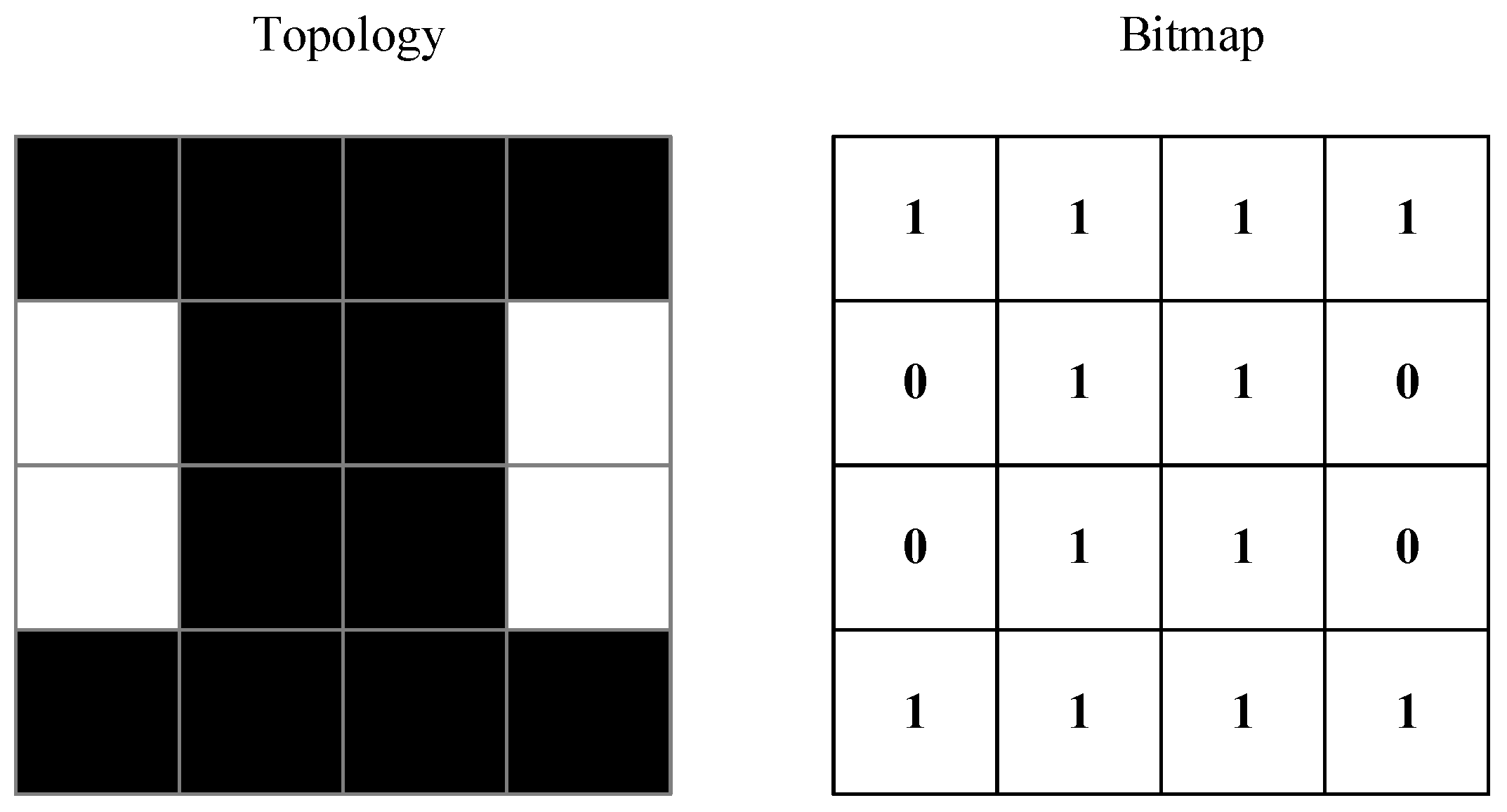
A broken feature only has some of the useful features and can lead to poor convergence characteristics. Therefore, 2D encoding became an alternative solution for certain problems. A demonstration of 2D encoded topology is shown in Figure 2. The bitmap matrix only has 0 and 1 values, a binary-encoded bitmap.
Cohoon and Paris first proposed 2D encodings and demonstrated moderate success in solving such a problem [16]. This approach led to the development of various crossover methods, which will be described in the following subsection.
2.2. Two-Dimension Genetic Operation
Compared with one-dimension encoding, 2D encoding consists of more graphic information [14,16,17]. In this study, 2D binary crossover and mutation are proposed.
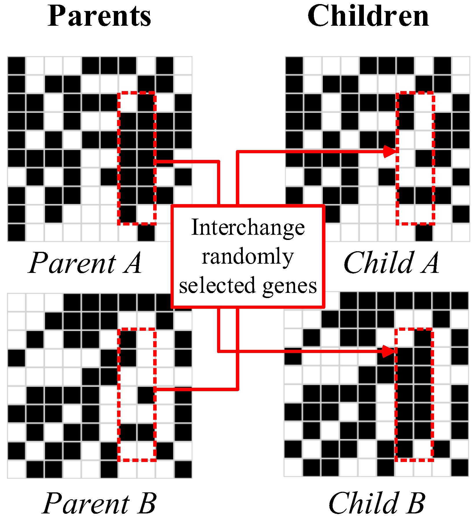
A crossover operator conventionally exchanges some information between two chromosomes with probability Pc. For 2D binary crossover, the input is two binary-encoded chromosomes cp1 and cp2. The output is two-binary encoded chromosomes co1 and co2. The 2D crossover is described as follows:
Step 1: Generate a random number R to represent the 2D crossover probability.
Step 2: If R < Pc, skip the crossover operation; otherwise, perform a 2D binary crossover.
Step 3: Generate four random int numbers x, y, dx, dy, representing the start position (x,y) in cp1 and cp2, and the horizontal and vertical distance of a small rectangular mask (dx,dy).
Step 4: The masked 2D rectangle will make a copy but only swap the masked area. Detailed operation can be found in Figure 3, the (x,y) = (6,1), (dx,dy) = (2,7), and the masked area size is 14.
Step 5: The content inside the masked area (inside the red box) will be interchanged; the interchanged outputs are co1 and co2.
The mutation is a genetic operator used to maintain the genetic diversity of a population of chromosomes between generations with the probability Pm. For a 2D binary mutation, the input is one binary-encoded chromosome cp. The output is one binary encoded chromosome co. The 2D mutation is described as follows.
Step 1: Generate a random number R representing the 2D mutation probability.
Step 2: If R < Pm, skip the mutation operation; otherwise, perform a 2D binary mutation.
Step 3: Generate four random int numbers x, y, dx, dy, representing the start position (x,y) in cp1 and cp2, and the horizontal and vertical distance of a small rectangular mask (dx,dy).
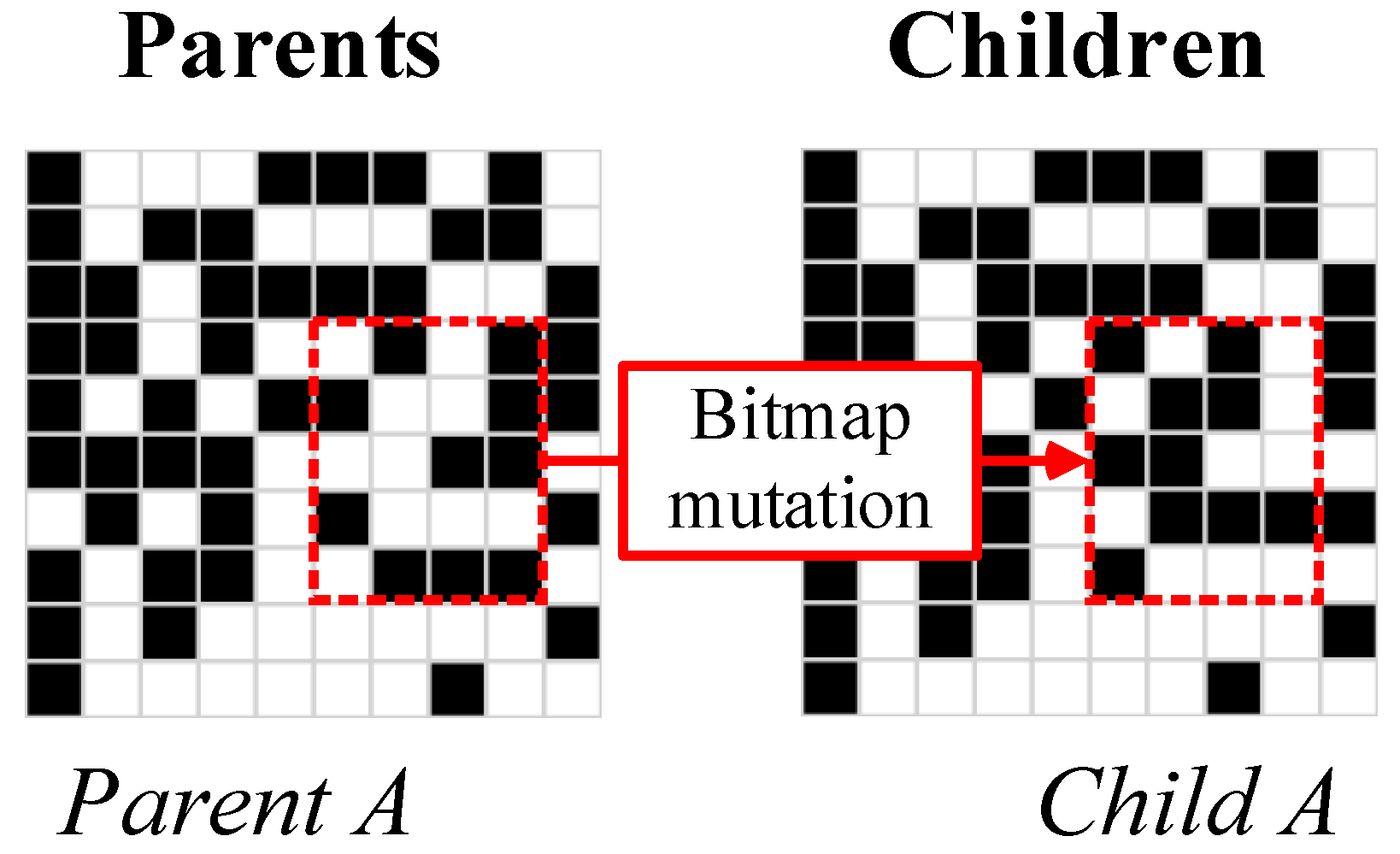
Step 4: The masked 2D rectangle will make a copy, the new copy is the unprocessed output co. Detailed operation can be found in Figure 4, the (x,y) = (5,2), (dx,dy) = (3,4), and the masked area size is 12.
Step 5: The content inside the masked area (inside the red box) will be flipped in co, and the interchanged output is the flipped co.
2.3. High-Resolution Interpolation
Although 2D encoding could solve real problems, Sigmund points out that for non-gradient topology optimization (NGTO) problems, coarse elements in the design domain cannot correctly represent the underlying physical problems [18]. Moreover, the coarse element will not cover optimal solutions with a fine scale. However, in TO for electric motors, the number of holes inside the rotor is relatively small. Therefore, though fine mesh with additional elements is needed for the TO of electric motors, the topology is simpler than mechanical TO. The binary-encoded GA can be a potential solution for TO.
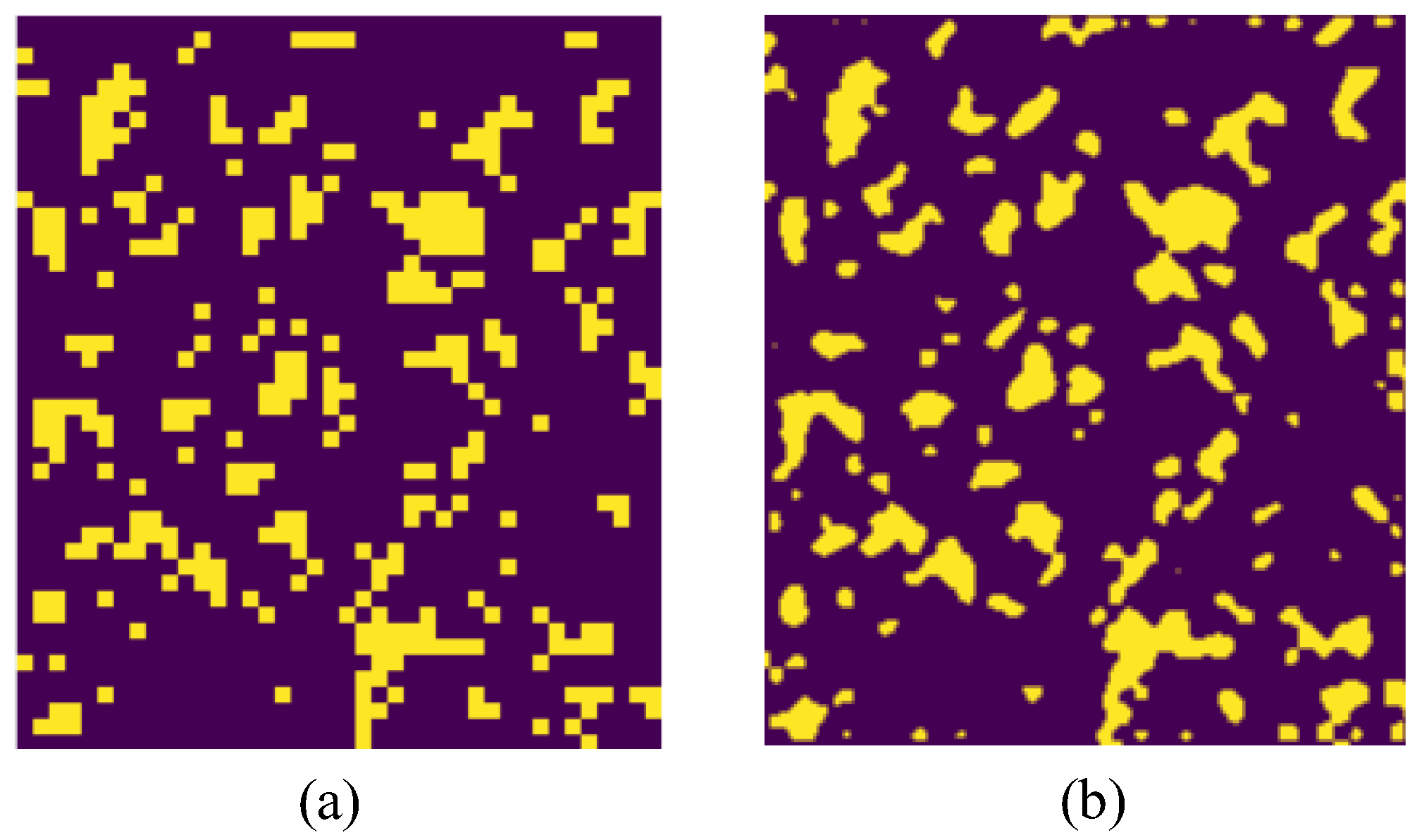
This section uses an interpolation method to make the bitmap, i.e., the 2D coarse topology, into a high-resolution topology. The interpolation method is B-spline interpolation with a smoothing factor of zero. Figure 5 shows a demonstration of 2D topology interpolation.
The level of the interpolated topology is determined by a constant c.
3. Convert CAD Model Using Edge Smoothing Method
Most topology results obtained using density-based methods are described in matrix-based elemental densities during topology optimization. Since the 2D matrix-based topology describing the finite element model is based on a constructed mesh, this introduces a jagged shape that leads to inaccurate results, making it difficult to evaluate some critical properties of the motor, such as cogging torque, with this approach.
Therefore, manual interventions are required to process the topology optimization results to produce accurate computer-aided design (CAD) models. The density threshold method is the most widely used; in this method, the contours of the density matrix are used to extract the boundaries.
However, this method requires a suitable density threshold to obtain valid results. Moreover, if this method is used to obtain CAD models of complex structures, fragile parts, rough surfaces, and disconnected structural components (isolated islands) may appear.
This section proposes an automatic process of converting bitmap topologies into DXF models. After the generated topologies, the small-sized topologies are removed, and the large ones are kept. This method is described as follows:
Step 1: Find the boundaries of the topologies.
Step 2: Extract the boundary points and use a cubic uniform B-spline curve to obtain the fitting curves of the topology.
Step 3: Identifying the small features. Find the small, closed, disconnected structural topologies and remove them based on the predefined threshold.
Step 4: Approximate the B-spline curve using a two-point line to reduce model complexity when generating mesh in finite element analysis.
The whole process can be found in Figure 6.
4. Two-Stage Simulation
Two-stage simulation is proposed to acquire the accurate torque angle for rotors with PM inside, such as IPMSM and PM-assisted SynRM.
The output torque of an interior permanent magnet (IPM) motor is composed of two components, namely the PM torque and the reluctance torque. The output torque can be expressed as:
where, , , and are the synthetic torque, the PM torque, and the reluctance torque, respectively; is the pole-pair number; is the PM flux linkage; is the amplitude of phase current; is the current advancing angle; and and are d- and q-axis inductances, respectively.
As clearly shown in (1), the frequencies of the PM torque and the reluctance torque waveform are different, where the frequency of the reluctance torque is twice that of the PM torque [19]. The synthetic torque represents the actual output torque of the IPMSM. The maximum value of synthetic torque occurs at a current advancing angle between the maximum values of the PM torque and the reluctance torque.
As the current advancing angle of the maximum value of the synthetic torque of an IPM SM is uncertain due to the variation of machine topology and the initial rotor position, it is vital to perform the simulation of machine performance in two steps. The initial current advancing angle of maximum synthetic torque is captured in the first step, and the full-load simulation is conducted to obtain the average torque and torque ripple in a subsequent step. In the following sections, the principle of MTPA control strategy is introduced first, and the detailed operation method of obtaining the maximum value of average torque and minimum value of torque ripple in the full-load operation of an IPMSM is described in a later section.
4.1. MTPA Control Strategy
In the IPMSM system, the transformation of coordination systems is usually performed to convert the static three-phase coordination system to the rotational two-phase coordination system. Clarke transformation and Park transformation are applied in this process. As a result, the three-phase armature currents can be decoupled to d- and q-axis currents, and a vector control (VC) can be realized.
MTPA is the abbreviation of maximum torque per ampere, which is a common control strategy in IPMSM. Compared to the id = 0 control strategy, MTPA is suitable for electric machines with a notable difference between d- and q-axis inductances, including IPM SMs, PM-assisted synchronous reluctance machines (PMA-SynRM), and so on. With a suitable distribution of d-axis and q-axis currents, the output torque over the unit armature current can be maximized. Ref. [20] presents the current torque characteristics of PMSM machines. The MTPA curve is obtained by connecting the closest point to the origin of the constant torque curves.
The MTPA curve can also be obtained by using the concept of the current limit circle, as shown in (2)–(5):
where is is the vector expression of stator current. When the magnitude of is remains constant, the MTPA control strategy can realize a maximum output torque. Meanwhile, the MTPA control strategy can improve the system’s dynamic response and overall efficiency.
4.2. Realization of MTPA in the Simulation of AIPMSM
As stated in previous sections, the MTPA control strategy is suitable for IPMSMs to generate the largest torque with stator armature currents with a constant magnitude. In the machine optimization process, the maximum value of output torque and minimum value of torque ripple are usually taken as the objectives. Therefore, it is necessary to perform the simulation in two steps. Figure 7 shows the workflow for the two-stage simulation during the MOGA.
4.2.1. Simulation of Output Torque under Locked Rotor Operation
In the first simulation, the rotational speed of the IPMSM rotor is set to zero, and the armature current is input as normal three-phase currents for the generation of a rotational magnetic field, as shown in (6)–(8).
where is the amplitude of stator phase currents, and is the electric frequency of armature currents. The maximum output torque of the machine occurs at a certain electric angle between the magnetic fields generated by the armature currents on the stator and the excitation PM on the rotor, which is the initial current advancing angle that we would like to capture in this step. Ansys Maxwell is used in the simulation process. The initial current advancing angle is obtained as a value of the initial time of the current phase, where the initial current advancing angle can be obtained by . The output torque at the initial current advancing angle is the maximum torque that can be generated at a stator current with a constant magnitude, which conforms to the working principle of the MTPA control strategy.
4.2.2. Simulation of Output Torque under Full-Load Operation
As the initial current angle is obtained in the previous step, and the full-load simulation of output torque is conducted in the subsequent step. The initial phase of the current angle is modified by inserting the time into the expression of phase currents, as shown in (9)–(11):
Meanwhile, the machine’s rotor is set to rotate at the rated operation speed. With a corresponding frequency of the armature three-phase currents, the rotor excitation field and the stator armature field are coupled, and stable output torque is produced. The machine’s average torque and torque ripple are obtained in this second step simulation process, and the optimization is proceeded according to the results of machine performance.
5. Results
5.1. Machine Configuration
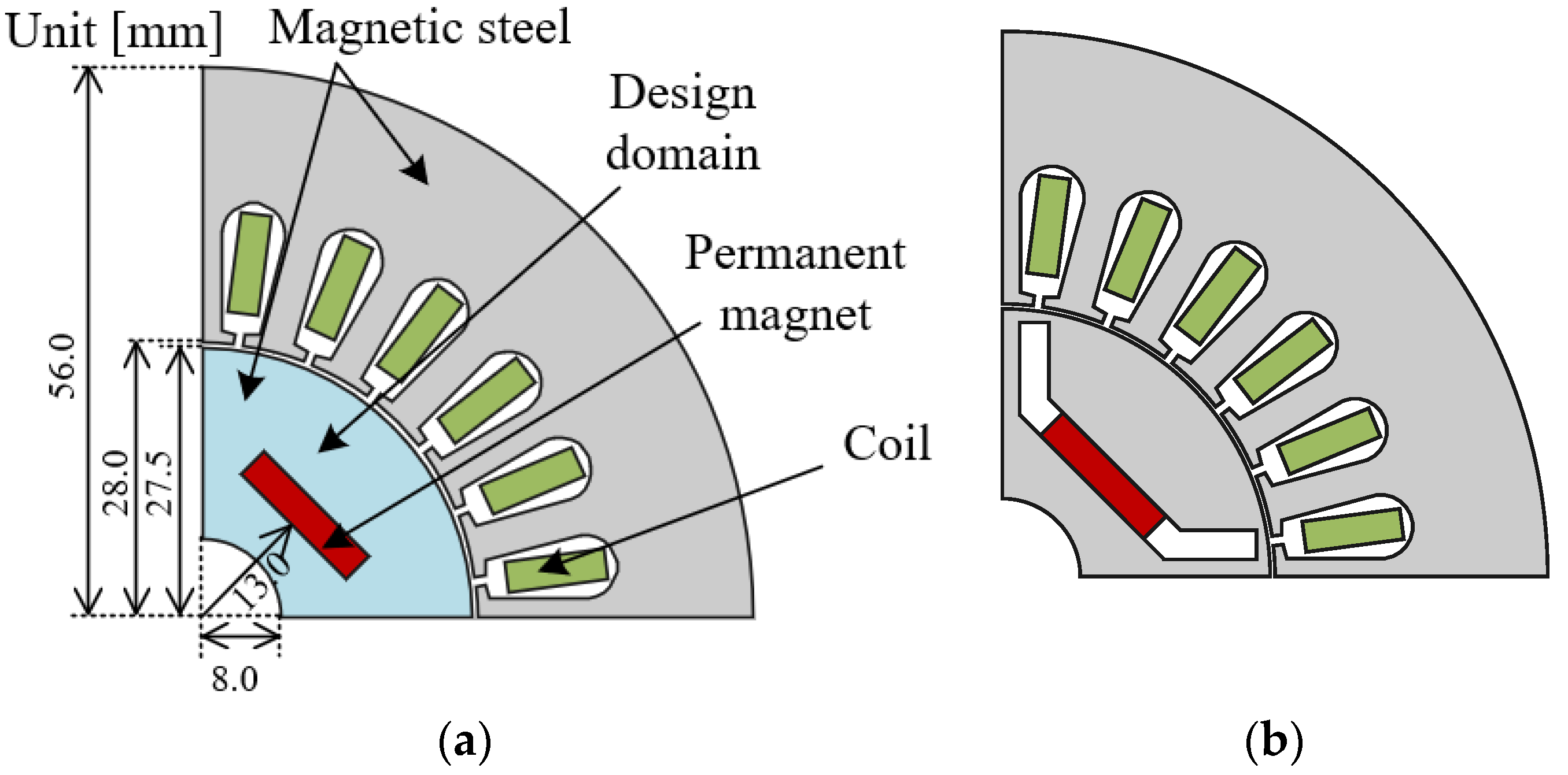
The design object is the rotor of a 24-slot 4-pole AIPMSM. The motor characteristics are as follows: the stator outer diameter is 246 mm, the stator inner diameter is 112 mm, the stator stack length is 50 mm, the outer rotor diameter is 56 mm, the inner diameter of rotor lamination is 16 mm, and the lamination thickness is 0.35 mm. The number of stator slots is twenty-four. The design region is not one-eighth but one-quarter of the rotor region, as shown in Figure 8, because we assume that the rotor shape is asymmetric in one pole region. The material is distributed in 1840 cells at the first iteration, composed of 46 by 40 parts.
This optimization aims to maximize the torque average and minimize the torque ripple of the AIPMSM.
The two objective functions are defined by:
F1 and F2 are minimized, which are the average torque and torque ripple.
This study applies a modified non-dominated sorting genetic algorithm II (NSGA-II) method with a two-stage torque angle evaluation process. Two objective functions, including maximizing average torque (F1) and minimizing torque ripple (F2), are evaluated using finite element analysis (FEA).
The population with a high ranking is reproduced in the next generation. We adopted 2D binary crossover and 2D binary mutation to produce a diversified population. The number of populations and generations are 40 and 250, respectively. The crossover factor is 0.9, and the mutation factor is 0.1. The optimization process is shown in the flowchart in Figure 9.
5.2. Design Domain of Asymmetric Rotor
5.3. Experimental Environments
The FE software used in this study is Ansys Maxwell, and the optimization framework is developed based on Python combined with Platypus [21] and NumPy [22].
This study shows that for the 100th generation, the computation time on a workstation with two Intel Xeon Gold [email protected] GHz is about 144 h, with the number of cells and generations set to 46 × 40 = 1840 and 10,000, respectively.
5.4. Optimal Solution for Asymmetric Rotor
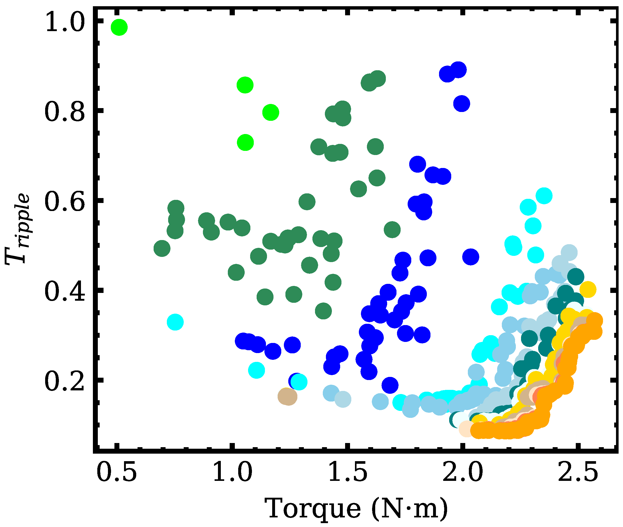
Final optimization results are obtained by the topology optimization framework using the proposed methods. The obtained Pareto-front solution is shown in Figure 11. The point set with orange color is the final solution set after the 100th generation.
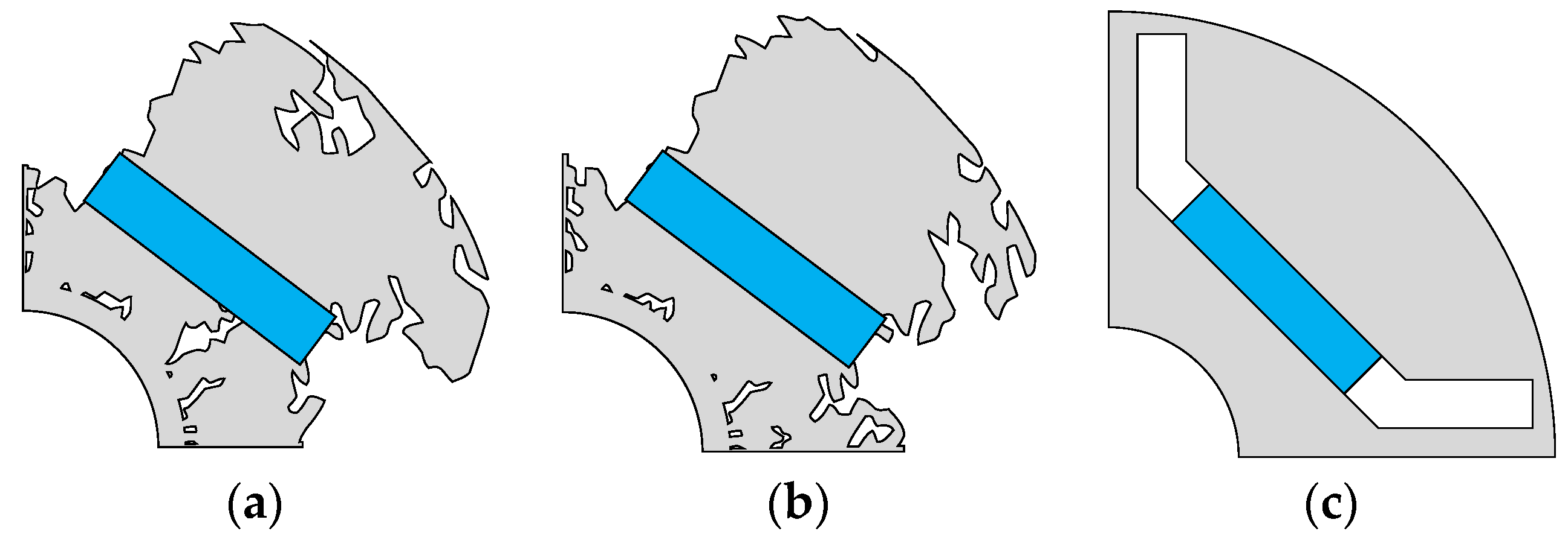
The values of and of the selected optimized models are shown in Figure 12. It can be observed from these results that both and are improved by the proposed method. As a result, the solution obtained by this present method has a smaller objective function value than the conventional method.
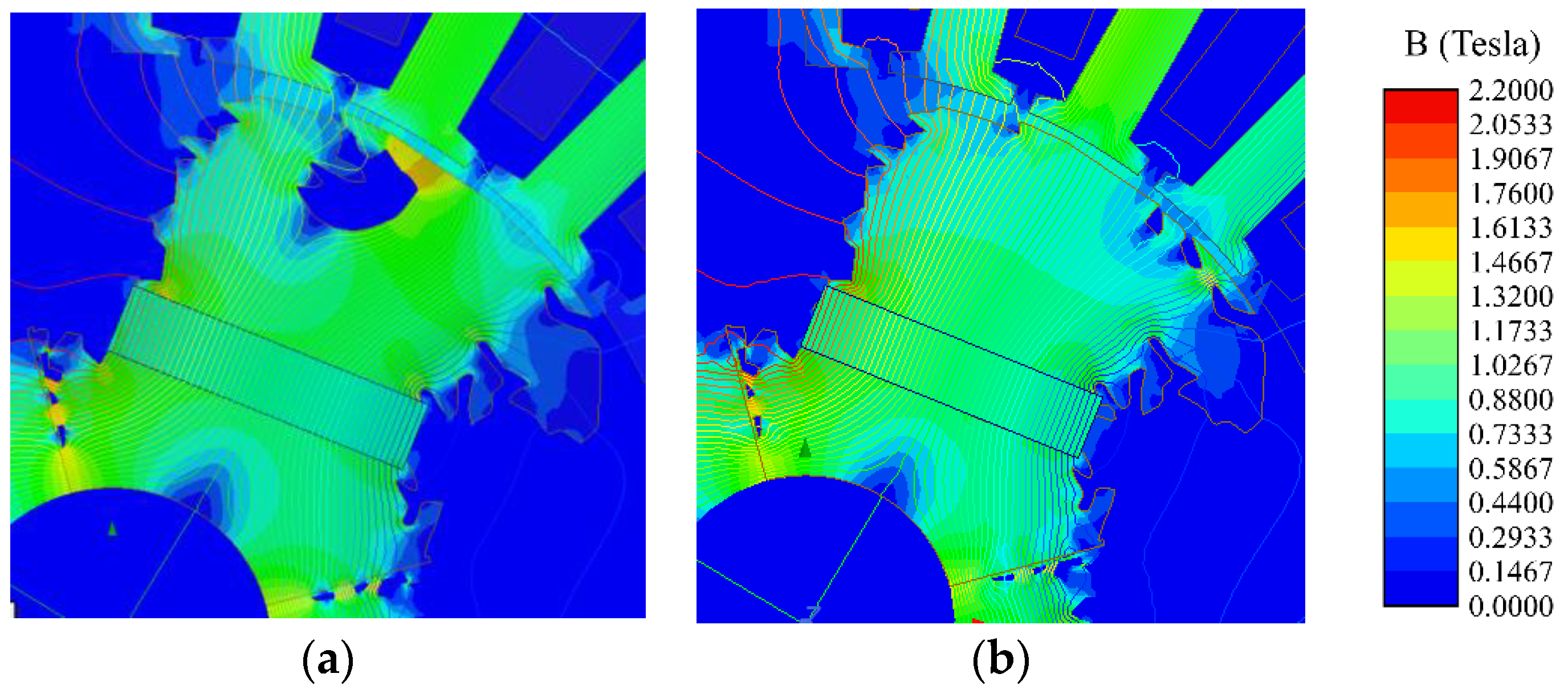
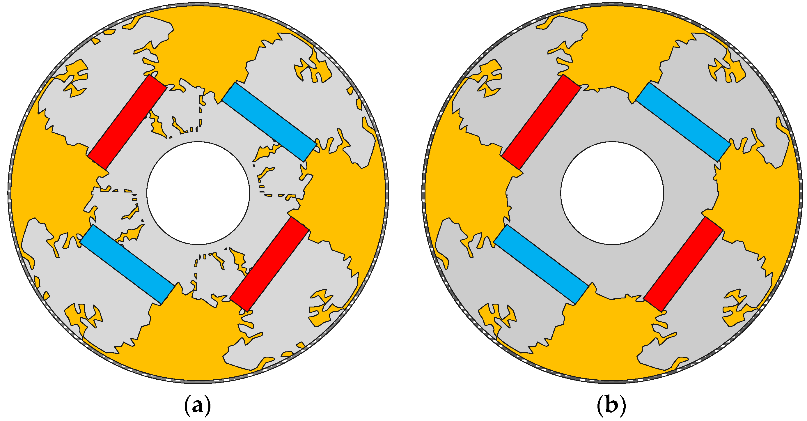
Figure 13 shows the flux density distribution and flux lines of the two selected optimized raw designs. According to the topology optimization, the design domain of low flux density has been deleted to meet the requirement of the constraints for higher torque and lower torque ripple. Model 0 forms a hole or a flux barrier in the rotor, and the torque ripple of model 0 is smaller than model 1.
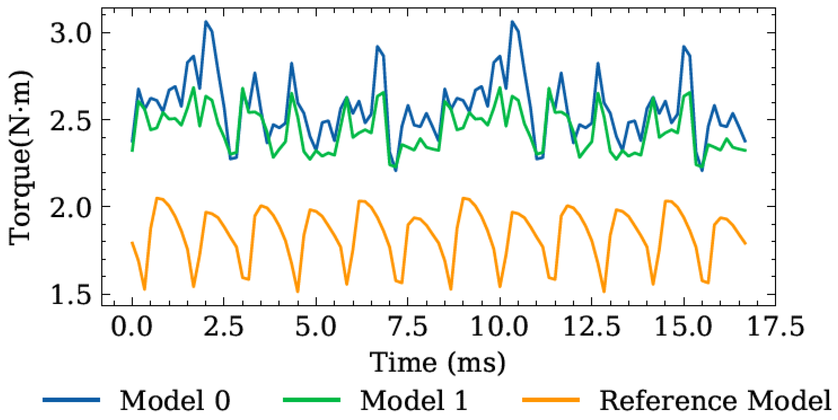
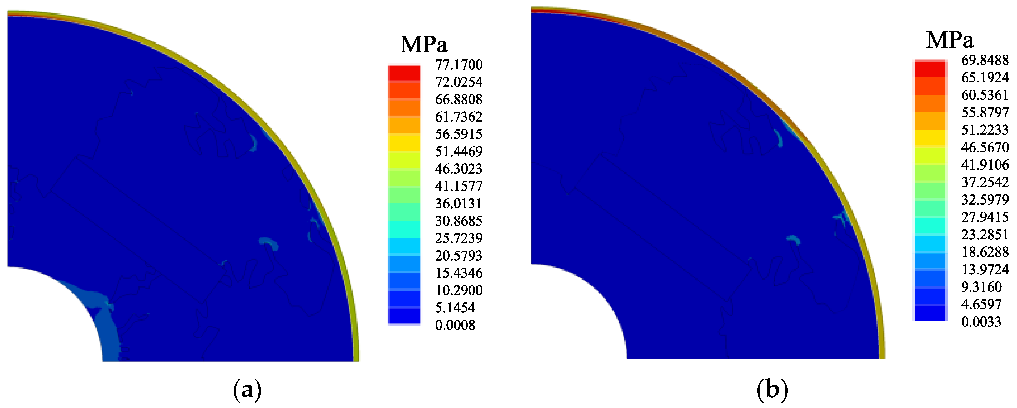
Figure 14 shows the comparison of torque waves of the proposed method and the conventional method. Model 0 has lower torque and lower torque ripple, while model 1 has higher torque and higher torque ripple. Compared with the reference model, both selected optimized models have at least a 30% torque increment. However, the torque ripple of model 1 is 60% larger than the reference model. Therefore, regarding the topological structure’s feasibility and performance, model 0 is selected for further simplification. Figure 15 shows the complete mechanical structure of the original model 0 and simplified model 0. Resin epoxy is used to fill the empty parts. A 0.25 mm thick carbon fiber sleeve prevents the optimized AIPMSM rotor from expanding, due to radical acceleration. The performance of simplified model 0 is slightly better than the original one. The von Mises stress distributions of the original model 0 and the simplified model 0 is shown in Figure 16.
6. Conclusions
A novel topology optimization method for AIPMSM based on two-stage simulation, high-resolution encoding, and edge smoothing is presented in this paper. In this present method, the global search is conducted using modified binary-encoded NSGA-II. Then, the solution obtained by the global search is improved by the post-processing method to simplify the optimized model. The topology of the rotor of AIPMSM has been optimized to test this present method. Compared with the reference model, we have found that the quality of the optimized solutions is much improved by this present method. Despite the increased computational time of the model, better results are obtained with the help of the CAD model during the TO, representing a more feasible electromagnetic structure.
Author Contributions
Conceptualization, H.W., S.N., and W.F.; methodology, H.W.; software, H.W.; validation, H.W.; formal analysis, H.W.; investigation, H.W.; resources, H.W.; data curation, H.W.; writing—original draft preparation, H.W.; writing—review and editing, S.N.; visualization, H.W.; supervision, S.N.; project administration, S.N.; funding acquisition, S.N. All authors have read and agreed to the published version of the manuscript.
Funding
This work was supported by the Research Grant Council of the Hong Kong Government under Project PolyU 152109/20E.
Data Availability Statement
Not applicable.
Conflicts of Interest
The authors declare no conflict of interest.
References
- Eschenauer, H.A.; Olhoff, N. Topology Optimization of Continuum Structures: A Review*. Appl. Mech. Rev. 2001, 54, 331–390. [Google Scholar] [CrossRef]
- Sigmund, O.; Maute, K. Topology Optimization Approaches: A Comparative Review. Struct. Multidisc. Optim. 2013, 48, 1031–1055. [Google Scholar] [CrossRef]
- Bendsøe, M.P.; Kikuchi, N. Generating Optimal Topologies in Structural Design Using a Homogenization Method. Comput. Methods Appl. Mech. Eng. 1988, 71, 197–224. [Google Scholar] [CrossRef]
- Okamoto, Y.; Hoshino, R.; Wakao, S.; Tsuburaya, T. Improvement of Torque Characteristics for a Synchronous Reluctance Motor Using MMA-Based Topology Optimization Method. IEEE Trans. Magn. 2018, 54, 1–4. [Google Scholar] [CrossRef]
- Lee, C.; Lee, J.; Jang, I.G. Topology Optimization for the Manufacturable and Structurally Safe Synchronous Reluctance Motors with Multiple Iron Webs and Bridges. IEEE Trans. Ind. Electron. 2022, 70, 678–687. [Google Scholar] [CrossRef]
- Lee, C.; Jang, I.G. Topology Optimization Framework for Simultaneously Determining the Optimal Structural Design and Current Phase Angle of the IPMSMs for the MTPA Control. IEEE Trans. Ind. Electron. 2022, 1. [Google Scholar] [CrossRef]
- Choi, J.S.; Yoo, J. Structural Topology Optimization of Magnetic Actuators Using Genetic Algorithms and ON/OFF Sensitivity. IEEE Trans. Magn. 2009, 45, 2276–2279. [Google Scholar] [CrossRef]
- Chapman, C.D. Structural Topology Optimization via The Genetic Algorithm, Massachusetts Institute of Technology. 1994. Available online: https://core.ac.uk/download/pdf/4400373.pdf (accessed on 1 October 2022).
- Chapman, C.D.; Saitou, K.; Jakiela, M.J. Genetic Algorithms as an Approach to Configuration and Topology Design. J. Mech. Des. Trans. ASME 1994, 116, 1005–1012. [Google Scholar] [CrossRef] [Green Version]
- Çunkaş, M.; Akkaya, R. Design Optimization of Induction Motor by Genetic Algorithm and Comparison with Existing Motor. Math. Comput. Appl. 2006, 11, 193–203. [Google Scholar] [CrossRef]
- Tai, K.; Prasad, J. Target-Matching Test Problem for Multiobjective Topology Optimization Using Genetic Algorithms. Struct. Multidiscip. Optim. 2007, 34, 333–345. [Google Scholar] [CrossRef]
- Lee, T.-H.; Lee, J.-H.; Yi, K.-P.; Lim, D.-K. Optimal Design of a Synchronous Reluctance Motor Using a Genetic Topology Algorithm. Processes 2021, 9, 1778. [Google Scholar] [CrossRef]
- Ruzbehi, S.; Hahn, I. Two-Level Topology Optimization of an Electromagnetic Actuator Based on Genetic Algorithm and Neighbourhood Method. In Proceedings of the 2020 IEEE International Conference on Industrial Technology (ICIT), Buenos Aires, Argentina, 26–28 February 2020; pp. 230–233. [Google Scholar] [CrossRef]
- Im, C.H.; Jung, H.K.; Kim, Y.J. Hybrid Genetic Algorithm for Electromagnetic Topology Optimization. IEEE Trans. Magn. 2003, 39, 2163–2169. [Google Scholar] [CrossRef]
- Xue, S.; Acharya, V. Topology Optimization Empowers the Design of Interior Permanent Magnet (IPM) Motors. In Proceedings of the 2020 IEEE Transportation Electrification Conference & Expo (ITEC), Chicago, IL, USA, 23–26 June 2020. [Google Scholar] [CrossRef]
- Cohoon, J.P.; Paris, W.D. Genetic Placement. IEEE Trans. Comput. -Aided Des. Integr. Circuits Syst. 1987, 6, 956–964. [Google Scholar] [CrossRef]
- Anderson, C.A.; Jones, K.F.; Ryan, J. A Two-Dimensional Genetic Algorithm for the Ising Problem. Complex Syst. 1991, 5, 327–333. [Google Scholar]
- Sigmund, O. On the Usefulness of Non-Gradient Approaches in Topology Optimization. Struct. Multidisc. Optim. 2011, 43, 589–596. [Google Scholar] [CrossRef]
- Zhu, Z.Q.; Xiao, Y. Novel Magnetic-Field-Shifting Techniques in Asymmetric Rotor Pole Interior PM Machines with Enhanced Torque Density. IEEE Trans. Magn. 2021, 58, 9464. [Google Scholar] [CrossRef]
- Ni, R.; Xu, D.; Wang, G.; Ding, L.; Zhang, G.; Qu, L. Maximum Efficiency Per Ampere Control of Permanent-Magnet Synchronous Machines. IEEE Trans. Ind. Electron. 2015, 62, 2135–2143. [Google Scholar] [CrossRef]
- Hadka, D. Platypus 2021. Available online: https://github.com/Project-Platypus/Platypus (accessed on 1 October 2022).
- Harris, C.R.; Millman, K.J.; van der Walt, S.J.; Gommers, R.; Virtanen, P.; Cournapeau, D.; Wieser, E.; Taylor, J.; Berg, S.; Smith, N.J.; et al. Array Programming with NumPy. Nature 2020, 585, 357–362. [Google Scholar] [CrossRef] [PubMed]
Figure 1.
A 1D encoding bit-array and equivalent topology.

Figure 2.
An example of topology bitmap representation (1–filled, 0–void).

Figure 3.
Illustration of 2D binary crossover.

Figure 4.
Illustration of 2D binary mutation.

Figure 5.
A demonstration of a bitmap using 2D interpolation with the contour parameter c = 0.5. (a) original topology (40 × 46), (b) interpolated topology (200 × 230).
Figure 5.
A demonstration of a bitmap using 2D interpolation with the contour parameter c = 0.5. (a) original topology (40 × 46), (b) interpolated topology (200 × 230).

Figure 6.
The overall process of high-resolution interpolation and edge smoothing method. (a) is binary encoded topology (10 × 10) for genetic algorithm, (b) is interpolated bitmap topology (50 × 50), (c) is smoothed edge based on using suitable density threshold, i.e., 0.5 in this figure, and (d) is the vectorized boundary (closed curve in red) for FE model.

Figure 7.
Workflow of two-stage simulation to get the accurate degree of torque angle for symmetric and asymmetric IPMSMs.
Figure 7.
Workflow of two-stage simulation to get the accurate degree of torque angle for symmetric and asymmetric IPMSMs.

Figure 8.
The design domain of the rotor.

Figure 9.
The flowchart of modified NSGA-II for TO. The two-stage simulation is performed in the evaluation process in the red box.
Figure 9.
The flowchart of modified NSGA-II for TO. The two-stage simulation is performed in the evaluation process in the red box.

Figure 10.
(a) is the configuration of the 24-slot 4-pole IPMSM, and (b) is the reference model.

Figure 11.
Obtained Pareto-front solution of every ten iterations.

Figure 12.
Selected optimized rotor topologies and the reference model. (a) is Model 0, the is 2.41 Nm, and the is 0.38 Nm. (b) is Model 1, the is 2.57 Nm, and the torque ripple is 0.85 Nm. (c) is the reference model, the is 1.83 Nm, and is 0.53 Nm.
Figure 12.
Selected optimized rotor topologies and the reference model. (a) is Model 0, the is 2.41 Nm, and the is 0.38 Nm. (b) is Model 1, the is 2.57 Nm, and the torque ripple is 0.85 Nm. (c) is the reference model, the is 1.83 Nm, and is 0.53 Nm.

Figure 13.
Magnetic flux line of optimal model 0 (a) and model 1 (b).

Figure 14.
Comparison of torque performance among Model 0, Model 1, and reference model.

Figure 15.
The whole model of the selected topology optimized AIPMSM rotors. The yellow parts are filled with resin epoxy, and a carbon fiber sleeve protects the whole rotor. (a) is the original model 0, the torque is 2.419 Nm, and the torque ripple is 0.308 Nm; (b) is the simplified model 0, the torque is 2.452 Nm, and the ripple is 0.366 Nm.

Figure 16.
The von Mises stress distributions at 3600 rpm for topology-optimized AIPMSM rotors, (a) is distribution of the original selected model 0, and the maximum von Mises stress is 77.1700 MPa, and (b) is the distribution of the simplified model, and the maximum von Mises stress is 69.8488 MPa.


Table 1.
Specification of reluctance motor.
| Property | Value |
|---|---|
| Number of Slots | 24 |
| Number of Poles | 4 |
| Type | Reluctance Motor |
| Design Domain Materials | Iron or Air |
| Speed | 3600 RPM |
| Air Gap Length | 0.5 mm |
| Excitation Source | Ideal Current Source |
Publisher’s Note: MDPI stays neutral with regard to jurisdictional claims in published maps and institutional affiliations. |
© 2022 by the authors. Licensee MDPI, Basel, Switzerland. This article is an open access article distributed under the terms and conditions of the Creative Commons Attribution (CC BY) license (https://creativecommons.org/licenses/by/4.0/).
Share and Cite
MDPI and ACS Style
Wu, H.; Niu, S.; Fu, W. Optimal Design of Asymmetric Rotor Pole for Interior Permanent Magnet Synchronous Motor Using Topology Optimization. Energies 2022, 15, 8254. https://doi.org/10.3390/en15218254
AMA Style
Wu H, Niu S, Fu W. Optimal Design of Asymmetric Rotor Pole for Interior Permanent Magnet Synchronous Motor Using Topology Optimization. Energies. 2022; 15(21):8254. https://doi.org/10.3390/en15218254
Chicago/Turabian StyleWu, Huihuan, Shuangxia Niu, and Weinong Fu. 2022. "Optimal Design of Asymmetric Rotor Pole for Interior Permanent Magnet Synchronous Motor Using Topology Optimization" Energies 15, no. 21: 8254. https://doi.org/10.3390/en15218254
Note that from the first issue of 2016, this journal uses article numbers instead of page numbers. See further details here.