
Implementation and Design of FREEDM System Differential Protection Method Based on Internet of Things


1
Department of Electrical Engineering, College of Engineering, Shaqra University, Al-Dawadmi, Riyadh 11911, Saudi Arabia
2
Electrical Engineering Department, Faculty of Engineering, Mansoura University, Mansoura 35516, Egypt
3
Department of Mechanical Engineering, College of Engineering, Shaqra University, Al-Dawadmi, Riyadh 11911, Saudi Arabia
4
Department of Mechanical Power Engineering, Faculty of Engineering, Zagazig University, Zagazig 44519, Egypt
*
Author to whom correspondence should be addressed.
Energies 2022, 15(15), 5754; https://doi.org/10.3390/en15155754
Submission received: 13 July 2022
/
Revised: 2 August 2022
/
Accepted: 6 August 2022
/
Published: 8 August 2022
(This article belongs to the Special Issue Modern Technologies for Renewable Energy Development and Utilization)
Abstract
:This paper introduces an enhancement of the protection and operation of the Future Renewable Electric Energy Delivery and Management (FREEDM) system. It uses the solid-state transformers to connect the residential A.C. and D.C. microgrids to the distribution system and fault isolation devices for faulty line isolation. In this paper, a current differential protection scheme has been proposed to detect faults in the FREEDM-based microgrid network. This method is based on the current measurement at the two-line terminals using phasor measurement units to ensure data synchronization and minimize the measuring error. Also, a communication scheme that is based on the Internet of things technology and Wi-Fi is constructed for data monitoring and interlinking between the relays, transducers, and the fault isolation devices in the two-terminals lines. A hypothetical FREEDM system has been used for the verification and testing of the proposed method. Different fault types at different locations and fault resistances have been applied to prove the effectiveness of the proposed protection method in detecting the fault condition. The performance of the proposed method is investigated using the security, dependability, and accuracy indices. A prototype of the FREEDM system is designed, implemented, and tested using the Proteus software simulator and in the laboratory. The results prove the efficiency of the proposed protection method in detecting and isolating the fault conditions in a fast, reliable, and accurate manner. Moreover, the protection scheme achieved high accuracy for all faults, equal to 98.825%.
1. Introduction
The electrical energy system is generally complex; it consists of generation, transmission, distribution, and load demands. Integrated small renewable energy sources with the electrical energy system are expected to significantly affect the distribution system management, protection, and operation [1]. Renewable energy resources are contributed to the electrical grids to satisfy the continuously increasing energy demand. Different renewable energy resources such as solar, wind, biomass, geothermal, and tidal are available nowadays [2,3].
Recently, distributed renewable energy (DRE) sources are increasing rapidly at the distribution grid with small penetration [4]. So, the DRE sources are considered economical energy sources because the transmission cost is reduced [5,6]. Moreover, the reliability of the electric power system will be increased by installing multi-DRE sources to feed the load demands [7]. The distribution system needs optimal operation of multi-DRE sources to satisfy the minimum energy and emission costs [8]. Moreover, the electrical faults can cause severe damage to various electrical power components [9]. Many methods were used to operate the power system securely during faults at the distribution networks [10]. Connecting the DRE sources to the radial distribution networks changes the power flow direction from uni-directional to bi-directional. The bi-directional flow of power has seriously impacted the efficiency of voltage regulation, operation, and protection systems [11,12]. Moreover, changing the levels of short circuits will lead to the loss of protective relays coordination causing maloperation for the protection system [13,14].
The DRE systems can be integrated with the conventional distribution systems in a microgrid (M.G.) or installed as an independent energy source [15,16,17]. The M.G. is a reliable and effective technique for increasing the reliability of the DER resources. However, the design and plan of the M.G.s are complicated due to the significant number of conditions that are required to improve the performance and cost. Each M.G. consists of several DRE sources that are connected to loads through single or three-phase feeders (lines/cables). They have several advantages, such as increasing system reliability, reducing energy costs, improving the voltage profile, and improving the distribution system efficiency. However, high DRE penetrations in the M.G.s negatively affect the operation, design, and protection of the distribution networks [16,17,18,19].
Several recent M.G.s protection methods have been presented to solve the abovementioned problems [20,21,22,23,24,25,26,27,28,29,30,31,32,33]. M.G. The protection scheme that was based on the dynamic security model included real-time protection, online calculation, and offline analyses [20]. The directional over current relay was used to protect the feeders. However, it required a long time to detect the fault [21]. Instead of the phase current, the negative and positive sequence currents were used to design the protection scheme [22,23]. But the coordination of the relays was complex due to the multiple settings. The magnitude of the transient voltage signal was utilized to locate the faults in the single-phase M.G.s [24]. A digital protection-based wavelet transform was applied to enhance the protection of M.G.s from different transient disturbances [25]. However, selecting the essential functions of the wavelet is complex. To avoid selecting the essential functions of the wavelet, the generalized S-transform [26] and the Hilbert–Huang transform [27,28] were applied to protect the M.G.s. The three-phase voltages’ amplitude and total harmonic distortion were used to design classifiers, including Naiva Bayes and Decision Tree, to protect only the islanded M.G.s [29,30]. A hybrid decision tree and the wavelet transform method were presented to detect the faults and classify them [31]. An intelligent differential relay-based data mining was applied to protect the M.G.s [32]. It used many feature components such as differential reactive power change and the rate-of-change of frequency. However, this method required a high sampling rate. The differential protection scheme and the feature cosine were used to protect the M.G.s [33].
Several adaptive protection schemes were proposed to protect the M.G.s [34,35,36,37,38,39,40,41,42,43,44]. An adaptive overcurrent protection scheme that was based on the setting group and programmable logic methods for an M.G. that was connected to the synchronous generators was proposed in [34]. The Internet of things (IoT)-based protection scheme was presented for protecting the multi-terminal high voltage direct current (MT-HVDC) [35]. There were two protection schemes that were presented: primary di/dt overcurrent protection and backup dv/dt under-voltage/overcurrent for the AC side. In Ref. [36], the feeders’ currents were continuously monitored then the protection center collected the data by communication links to protect them. The settings of the overcurrent relays were adaptively changed to obtain the optimum protection of the M.G.s [37]. However, this protection scheme is complicated due to the many uncertainty factors that are associated with the M.G.s. The fuzzy logic system-based M.G. protection was proposed in [38].
The method considered different types of uncertainty factors. Moreover, the phase angle between the current and voltage was used to detect the direction of the faults. An adaptive protection-based wavelet transform protects the M.G.s for various fault types [39,40]. These protection schemes required synchronization signals with a high sampling frequency. A differential protection method was presented in [41] to detect faults in the off-grid M.G.s only. This method was based on the current frequency components difference. Moreover, the convolution neural network and Gorilla Troops optimization algorithm was used as an adaptive protection relay for fault detection, identification, and localization [42]. Although this method has high accuracy and reliability, it requires a large amount of fault information to train the neural network. In [43], an intelligent distance protection scheme that is based on IEC 61850 communication channel is presented for the D.C. zonal shipboard M.G. However, an adaptive pilot distance protection scheme-based Fourier transform and communication channel was represented for ship M.G. in [44].
The Future Renewable Electric Energy Delivery and Management (FREEDM) system is an M.G. that depends mainly on the evolution of information technology, internet applications in power systems, power electronics, and communication systems [45,46]. The DRE sources can be solar panels, wind turbines, fuel cells, hydro turbines, biomass, or geothermal energy. Distributed energy storage (DES) devices such as batteries are applied to manage the available energy by an interface system. The FREEDM system integrates the DRE sources with DES devices to ensure dynamic system stability [47]. The integration between the DRE sources and the DES devices produced a stable and flexible system, either on-grid or off-grid. Also, in this system, the consumers can contribute to managing and regulating their energy requirements. They can reschedule the electrical loads using the central controller [46,48]. Moreover, integrating the DRE sources that are linked with the power electronic devices needs fault ride through to ensure that the electrical network is not affected by faults [49].
Several researchers have applied the differential protection method for the M.G. and FREEDM system. Authors in [50] introduced a differential protection method that was based on S transform for extracting the energy of the signal of current that was measured at the two Line’s terminals versus the time to detect the fault and identify the faulty phases. In [51], the fault data self-synchronization method is proposed for the current differential protection method using the current amplitude ratio on the two protected feeder terminals to reduce the time synchronization error and enhance the current differential performance. Authors in [52] demonstrated an adaptive differential protection method with directional protection based on incremental transient energy and the rate of change of current protection. In contrast, a current differential protection method was presented based on two-terminal percentage current differential relays and multiple time-delayed differential elements to ensure the coordination between different protection zones and sensitivity against the high fault resistance [53]. The fault classification process was enhanced with the current differential, its derivative, and the K-nearest neighbor method in the low voltage D.C (LVDC) network [54]. In [55], the fault data self-synchronization method was improved using the current slope’s polarity and the current zero-crossing time, indicating the starting delay difference at the two-terminal lines in the current differential protection. Besides, the fault detection process was enhanced by estimating the line resistance by local measurements at the bus terminals. The estimated resistance sign at the two-terminal lines indicated the fault condition [56]. The support vector machine method was applied for detecting the faults in an LVDC network [57]. Also, the fault detection and localization were determined using the fuzzy logic and the voltage transients-based differential protection scheme [58]. In [59], a differential protection scheme was investigated using the dynamic state estimation for radial M.G.s. In [60], the authors introduced a differential protection method that was based on the rate of change of power at the two- terminals lines in-ring M.G. for the fault condition identification. According to the literature review [50,51,52,53,54,55,56,57,58,59,60], the use of phasor measurement units (PMUs), applying the fault isolating devices (FIDs) and the use of an appropriate communication channel between the relay and the two FIDs in the two terminals of the protected line has not been considered.
This paper proposes a novel differential protection scheme for the FREEDM-based M.G. system. This method enhances the current measurement at the two-terminals of lines using the PMUs. The PMUs provide accurate current monitoring at the line terminals to achieve data synchronization and minimize the error in the measured current values. Also, the FIDs are applied at the two-terminals of the lines with the ability to isolate the faulty line in the system. FIDs are solid-state breakers with the advantages of fast switching and are more accurate than the other mechanical breakers. A solid-state transformer (SST) is implemented for the three stages D.C./A.C., D.C./D.C., and A.C./D.C. converters with communication capability. The IoT is applied for data monitoring/processing and provides an appropriate communication channel between the relay, transducers, and the FIDs based on the Wi-Fi channel. The proposed protection method is implemented and tested using a hypothetical FREEM-based M.G. system in MATLAB/Simulink. Different fault conditions have been tested, i.e., three-phase fault, single phase to ground fault, phase to phase fault, and double phase to ground fault. Also, the performance of the proposed method is investigated based on security, dependability, and accuracy indices. A prototype is designed and implemented using the Proteus software simulator and the laboratory.
The main contributions of this article could be listed as follow;
- Proposing a novel differential protection method for the FREEDM-based M.G. network.
- Using the FIDs in the two-terminals for the faulty line’s fast and accurate fault isolation process.
- Applying the IoT technology for the interlinking between the relay, transducers, and the FIDs in the two terminals of the protected line based on the Wi-Fi channel.
- Investigating the effectiveness of the proposed protection scheme using four fault conditions with different locations.
- Performing a performance analysis for the proposed protection method using security, dependability, and accuracy indices.
- Constructing a prototype of the FREEDM system and applying the protection method using the Proteus software simulator and in the laboratory.
The article organization is as; Section 2 illustrates the FREEDM system architecture, Section 3 introduces the proposed current differential protection scheme, Section 4 represents the simulation results and discussion, and Section 5 demonstrates the implementation of the prototype. Finally, the conclusion is presented in Section 6.
2. FREEDM System Architecture
FREEDM is a smart distribution grid that is integrated with highly DRE sources and distributed energy systems with the existing distribution systems. It has many DREs types and energy management solutions to minimize the losses and improve the flexibility of operation. Furthermore, it is equipped with a plug-and-play technique to integrate and control the different DRE resources in the distribution systems. FREEDM systems have high reliability and power quality [43].
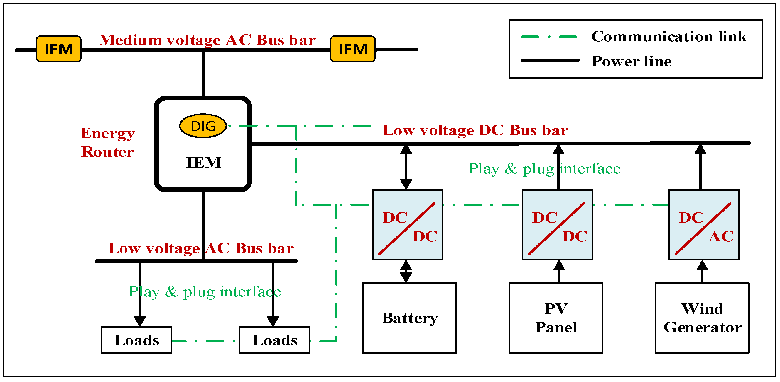
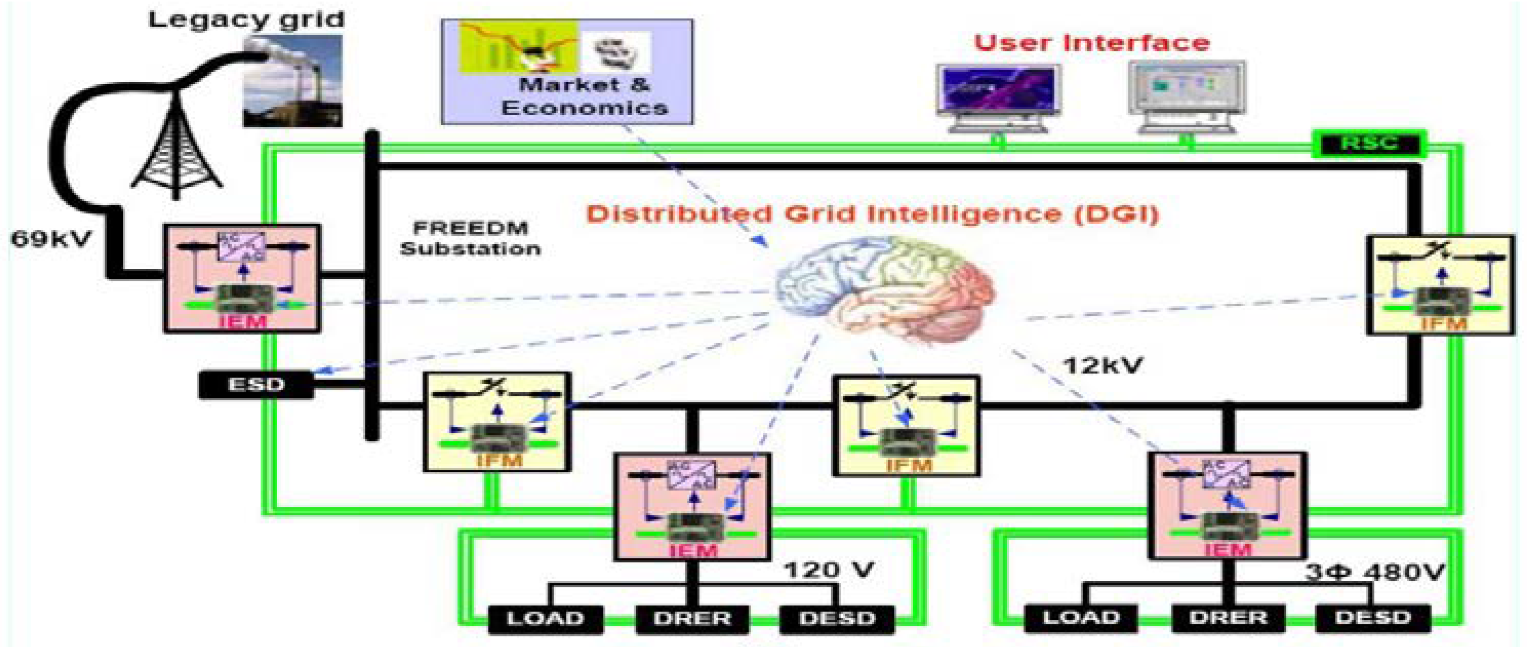
The conceptualized grid that is integrated with the future smart home or other types of loads in distribution voltage level is illustrated in Figure 1. There are three main components of the FREEDM system that are presented in Figure 2; the first component is the plug-and-play interface, which includes D.C. and A.C. buses and a communication interface. The second component is intelligent energy management (IEM) which connects and regulates the low and medium voltage buses (D.C. and A.C.). It also manages the devices that are connected to the low voltage D.C. and A.C. buses. Finally, the third component is the distributed grid intelligence (DGI), an open standard operating system that is integrated into the IEM device [44,45].
2.1. Distributed Grid Intelligence
Microgrid (M.G.) distribution operation consists of energy, power electronics management, and fault detection and recovery devices. Recently, supervisory control and data acquisition (SCADA) systems have been applied to control and manage the resources of energy systems. However, these centralized systems may not achieve full energy systems reliability and ownership. The distributed system structure is presented to control and manage the electric power resources within a smart microgrid. As such, control elements are installed in the M.G.s, which are not presented in the conventional distribution systems. This operating system is connected with the IEM devices and uses communication methods to manage the system with other energy routers. The DGI is built to implement the distributed operation algorithms for power device control in the smart grid (SG) [43], such as scheduling in real-time for the execution of distributed algorithms by using an integrated scheduler, detecting/configuring the DGI processes automatically, managing/integrating the devices with simulation programs, and capturing the SG state using a method that compensates for latency.
2.2. Fault Isolation Device
The solid-state circuit breakers (SSCBs) provide more accurate and fast switching operations than the mechanical circuit breakers to isolate the faults of the power systems. These SSCBs potentially improve the reliability of the electric distribution systems by reducing the power outage times and minimizing the possible damages to utilities or loads. The major challenge of applying the SSCBs in electric distribution systems is the large fault current interruption capability. For this reason, utilizing the SSCBs is desirable in the distribution systems having inherent current limitations. As the SSCB no longer needs extremely high interruption current capability, this type of SSCB called FID. The fault currents of the FREEDM system are often limited due to the use of power electronic devices. The FREEDM medium voltage A.C. bus is powered by an SST substation from the transmission grid [45,46].
2.3. Distributed Energy Resources and Storage Devices
The spread of renewable energy in the electricity sector has increased over the past few years. It represents any system that allows the generation of clean energy from sustainable sources which can constantly be replenished. The FREEDM system allows DRE sources such as PV panels and wind turbines, and DES such as batteries to be plugged and played through a protocol that achieves the system’s most economical and efficient results [61].
2.4. Solid-State Transformer
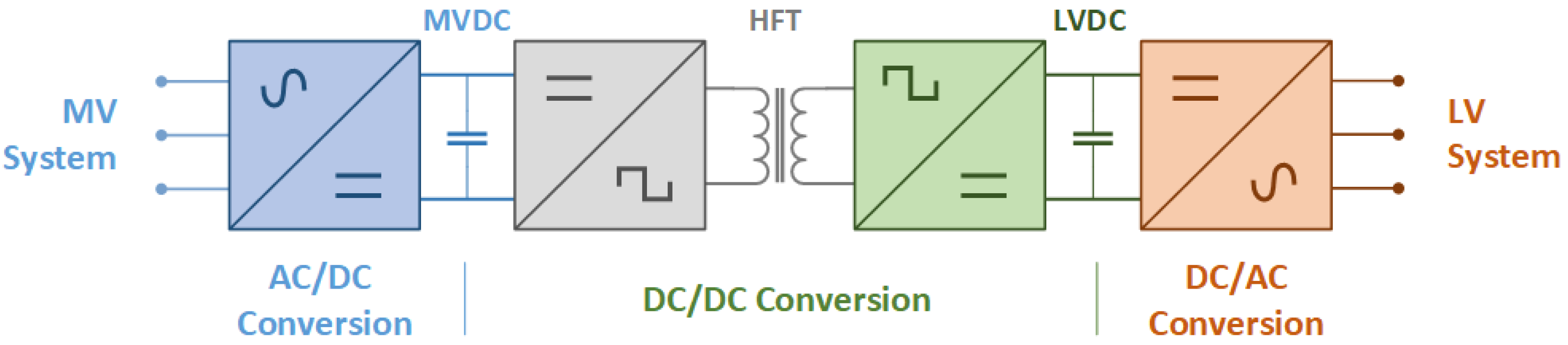
SST, alternately known as “smart transformer”, is a collection of high-powered semiconductors, high-frequency transformers control circuits, and communication capability. SST is a power electronics technology that can influence the developments in SGs. The SST can step-down or step-up A.C. voltages similar to a traditional transformer. Numerous SST topologies can be classified according to the number of stages; single-stage, two-stage, and three-stage [62,63]. Figure 3 illustrates the block diagram of the three-stage SST that can be described as follows.
2.4.1. A.C.–D.C. Stage
This stage is connected to a three-phase A.C. grid via R.L. filters. It can be considered a rectifier if the power moves from the MV to LV side of the SST. However, in the case of power flow reversal, this stage acts as an inverter.
2.4.2. D.C.–D.C. Isolation Stage
This stage includes three sections: D.C.–A.C. conversion stage, high-frequency transformer (HFT), and A.C.–D.C. conversion stage. The first stage is considered an inverter that can produce a high frequency to the HFT. The second stage is the HFT which is applied as electric isolation. It is the main reason for the size reduction compared to the conventional transformer. Therefore, HFT must be optimally designed to enhance the performance of the SST. The third stage is considered a rectifier that controls the HFT output current and the D.C.-link voltage at the LV-side to the nominal value.
2.4.3. D.C.–A.C. Stage
This stage is applied for the SST-LV side to ensure an optimal and balanced capacitor terminal voltage with a stable frequency, independently of the LV-side currents unbalance and the level of load/generation.
3. Proposed Protection Scheme
This section illustrates the structure and design procedures of the differential protection for the FREEDM system.
3.1. Design of the Differential Protection Scheme
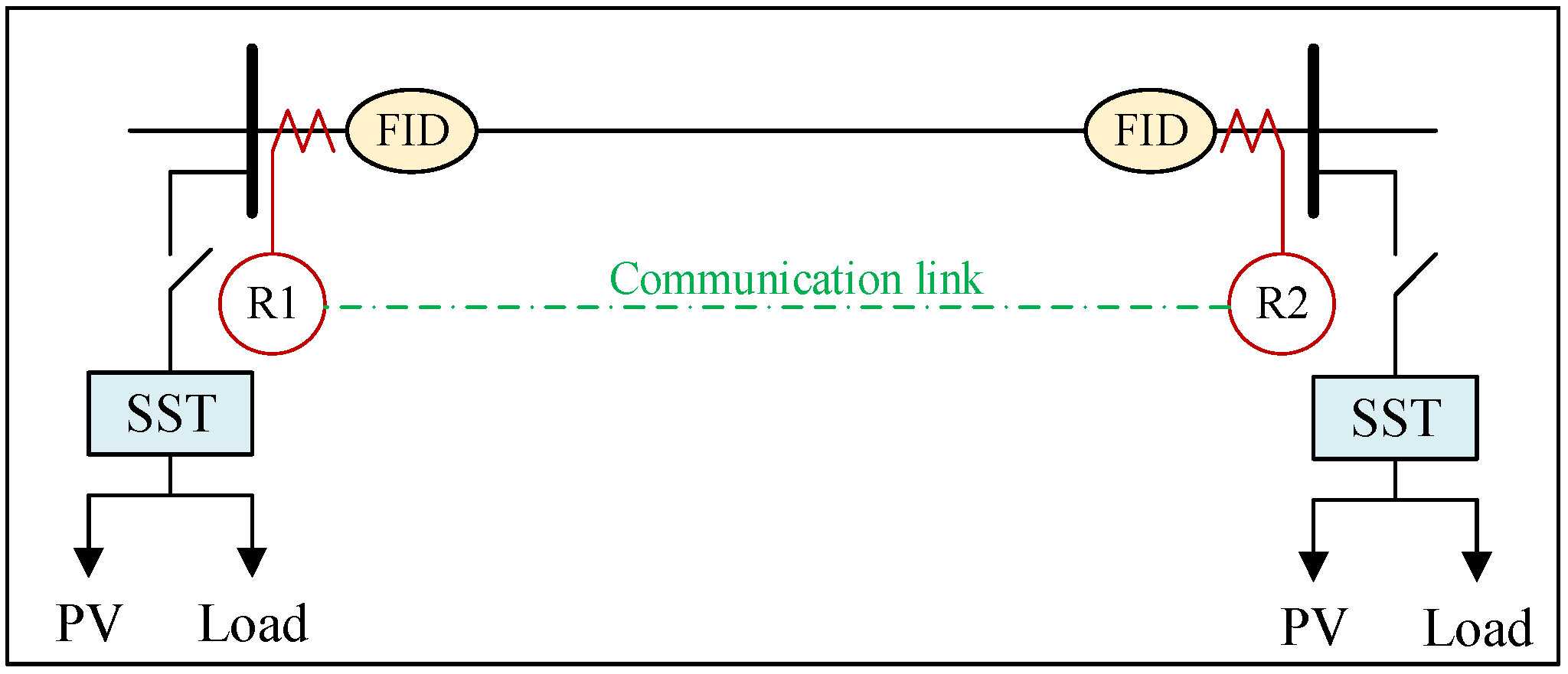
Each line in the M.G. is protected by measuring the currents and/or voltages at the two ends of the line. The current measurement is conducted using PMUs where the current at the two terminals of the protected lines is measured simultaneously. Hence, the data synchronization is enhanced, and the measurement errors are decreased. Current entering and leaving the line should be equal in normal operating conditions. However, this condition is not achieved during line faults. So, the current differential protection is used to protect the lines. The one-line diagram of the current differential protection scheme for line protection is illustrated in Figure 4. The two relays at the feeder ends are connected through a communication link that is based on the IoT protocol for a differential protection scheme.
This study proposes a complete protection scheme to protect the M.G. feeders for the two modes of operation (isolated and grid-connected) from various fault types. The bus voltages and fault currents are processed at the two feeder ends to detect the faults. The designed protection scheme uses the root mean square value of the voltage (RMS) and the positive sequence component of the fault current magnitude to detect the fault in M.G. feeders. The RMS value of voltage is used to prevent maloperation of the relay due to the transient overvoltage during the operating and fault conditions. Furthermore, the differential positive sequence currents are used to detect the faults.
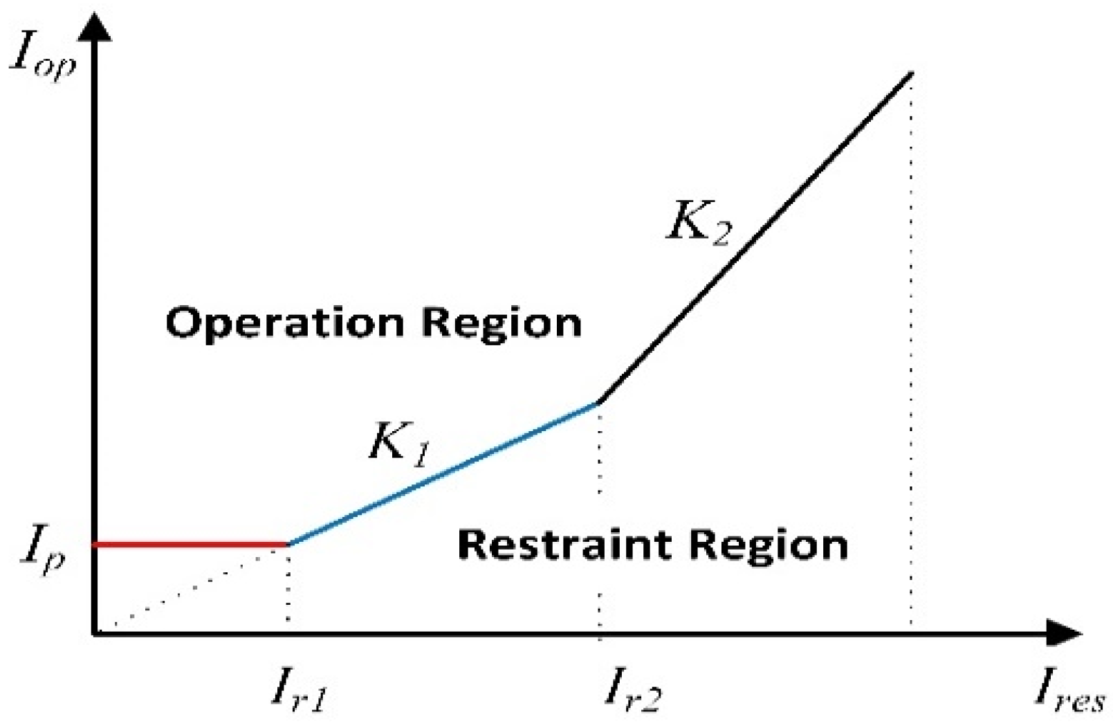
In percentage differential relays, the most common maloperation can occur due to the saturation and mismatch of the current transformer (CT). This maloperation current is a function of the restraint current. A dual slop percentage differential relay characteristic is used to overcome this problem, as shown in Figure 5. The operating current, Iop, and restraint current, Ires, can be expressed by [64];
where and are the positive sequence current magnitude of feeder currents. According to Figure 5, the characteristics of the percentage differential relay can be divided into three intervals; interval_1 (), interval_2 (), and interval_3 (). The principle of fault detection in each interval can be defined by:
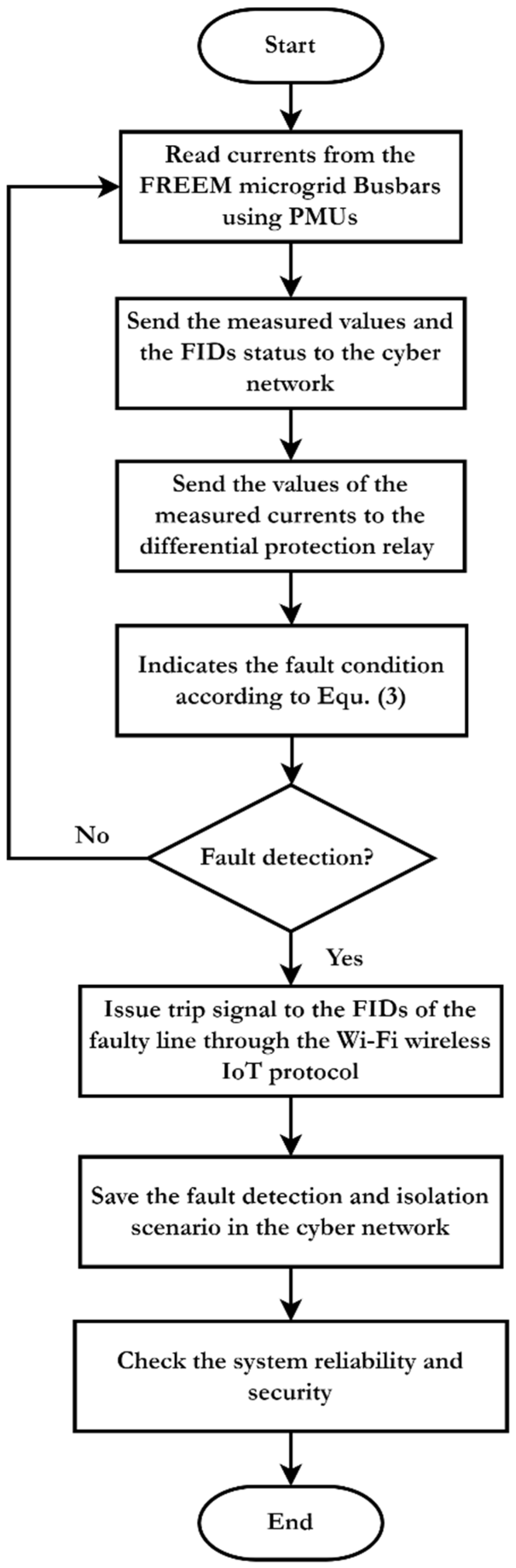
The proposed protection scheme procedures have been presented in Figure 6. Firstly, the currents at the line terminals are measured using the PMUs. Then, the measured data are processed to identify the fault condition using the differential protection principles. The information and data are stored in the IoT platform using memory. The stored data are the measured current at the line terminals, the relay decisions, the FIDs status, and the values of the transducers. After that, if there is a fault condition, the relay sends a tripping signal to the FIDs in the terminals of the faulty line to isolate it. The communication channel between the relays, transducers, and the FIDs are implemented using Wi-Fi and data distribution service (DDS) messaging protocol. The proposed protection method is illustrated using the flowchart in Figure 6.
3.2. Implementation of the Communication Channel-Based IoT Technology
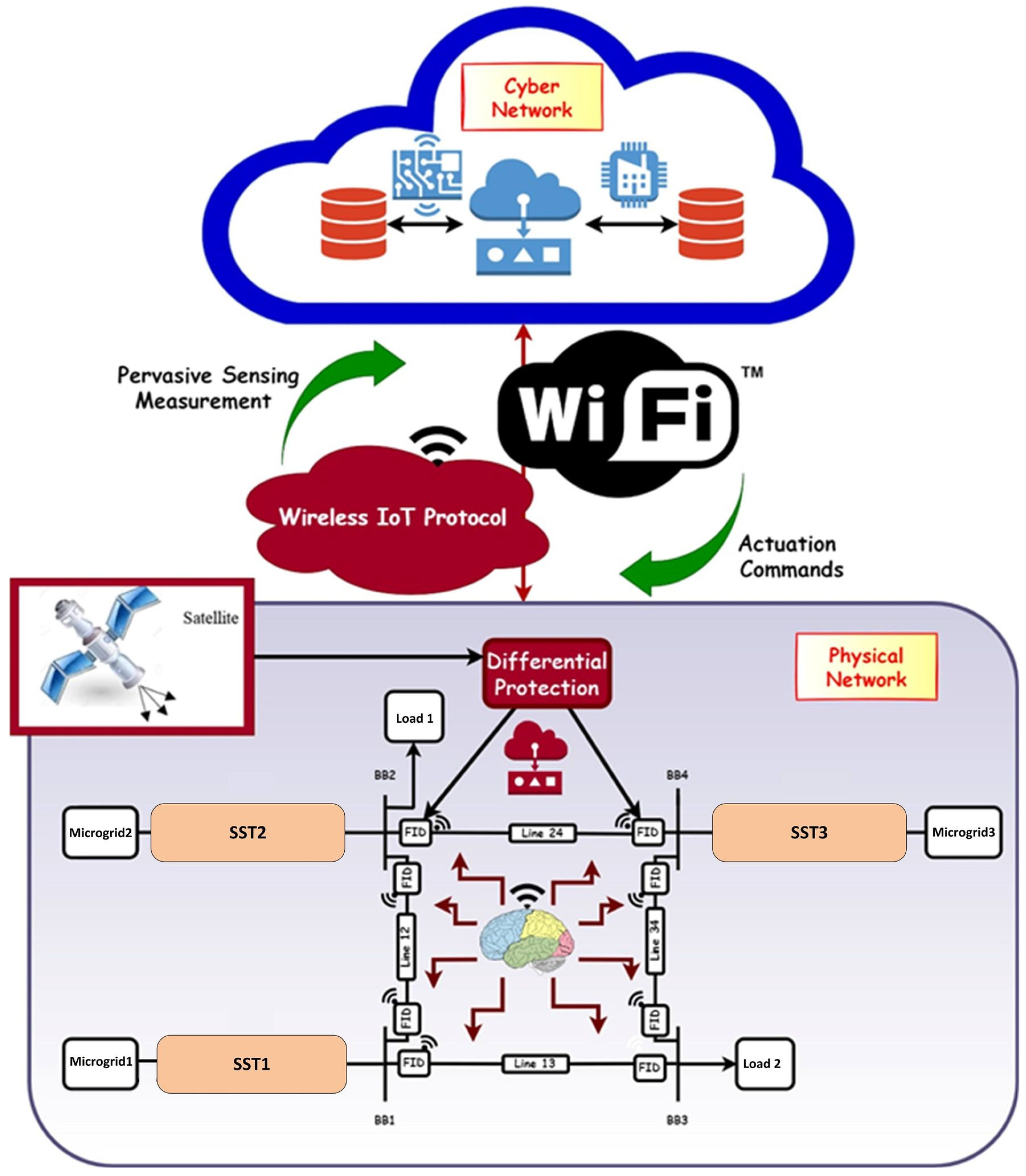
The IoT is applied to the protection method that is based on the Wi-Fi communication channel. It is applied for monitoring and data processing of the measured currents at the two terminals of the protected line. The Wi-Fi communication method has advantages of more flexibility, more extended range than Bluetooth and ZigBee, low power communication channel, and being closer to the network. It is applied to coordinate the protective devices: relays, transducers, and FIDs. As in the IEC61850 standard, the manufacturing message specification (MMS) communication protocol is applied for the local area network (LAN) and the DDS communication protocol is used in the wide-area network (WAN). This paper applies the DDS protocol for data middleware sharing among the protection system devices. It ensures real-time communication, reduces data access latency, increases communication performance, and enhances the transferred data reliability, scalability and dependability. This decentralized method can interlink and share the data and information between the relays, transducers, and FIDs in the protection scheme. The fault detection and system protection have been provided using Ethernet with the IEC 61850 standard or IEEE 802.11ah WLAN. The programming interface is Net, Java, C, and C++ for achieving the flexibility to integrate with different applications. The proposed IoT architecture is represented in Figure 7.
In this article, sampling frequency of the model is 100 kHz hence the sampling time is 10 µs. Also, the switching frequency of the FIDs is 10 kHz hence the switching time is 100 µs. The frequency rate of the Wi-Fi communication channel is 900 MHz. The communication channel and the DDS protocol enhance the monitoring of the FIDs status, the current magnitudes at the two line ends using the transducers and the relay at each protected line.
4. Simulation Results and Discussion
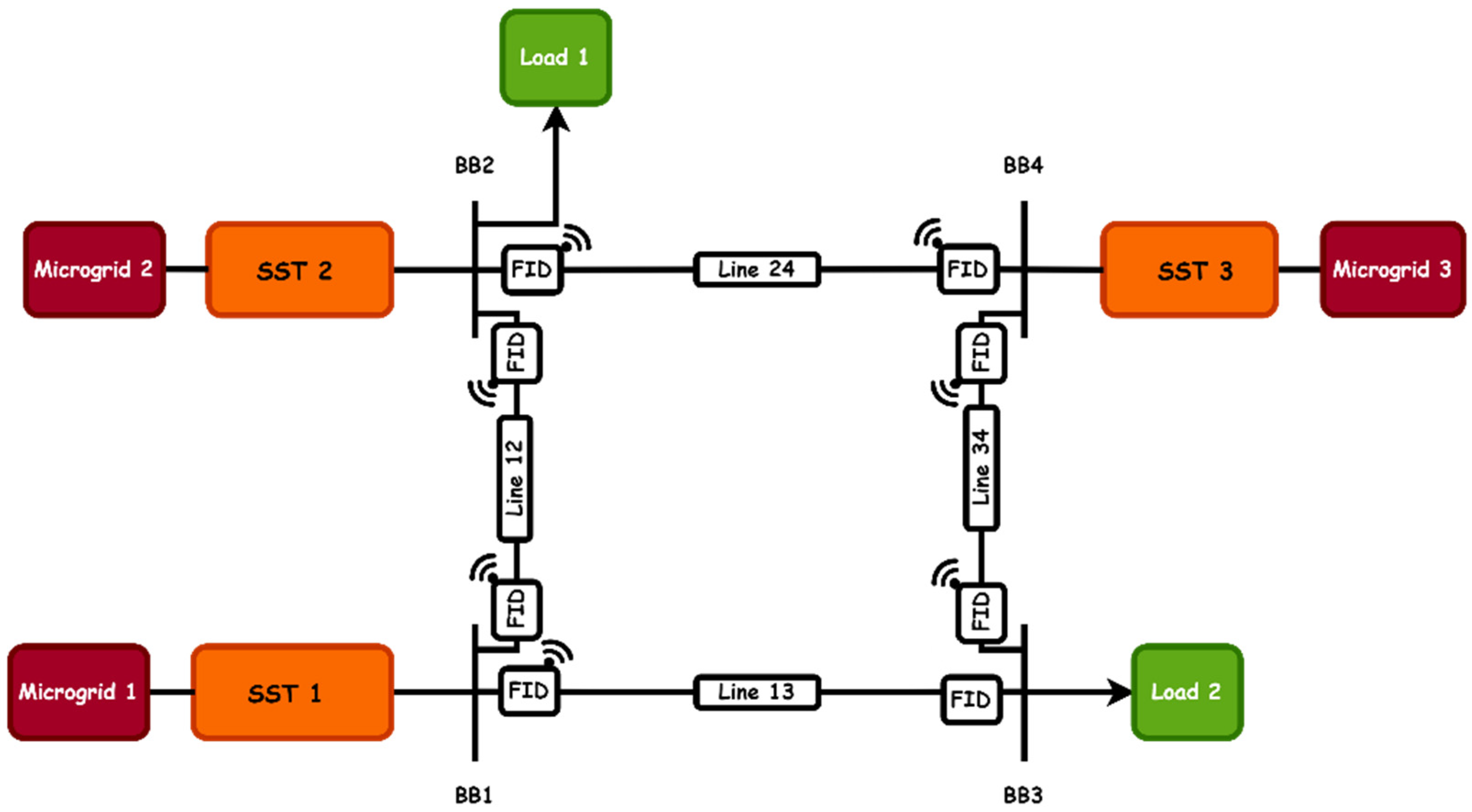
The proposed protection method is verified and tested by applying it to a hypothetical FREEDM system. Figure 8 illustrates the system architecture of the proposed FREEDM system. It consists of four buses and four lines. There are three microgrids sources that are connected to busses; BB1, BB2 and BB4. Two electric loads are connected to buses; BB2 and BB3. The sources in the microgrids are based on the RESs such as wind energy (WE) and photovoltaic (PV). These sources are connected to three stages SST with two D.C. links called LVDC and MVDC. Each transmission line has two FIDs and SSCBs at its ends. The applied communication platform is based on the IoT. The IoT platform includes two layers; the physical layer represents the FREEDM system and the cyber layer for data analysis, processing, and storage. The communication between the cyber and physical layers is based on Wi-Fi. The FREEDM system parameters are represented in Table 1.
Three cases are applied to the FREEDM system as follows:
- Normal operation
- Fault condition
- Applying the proposed protection scheme
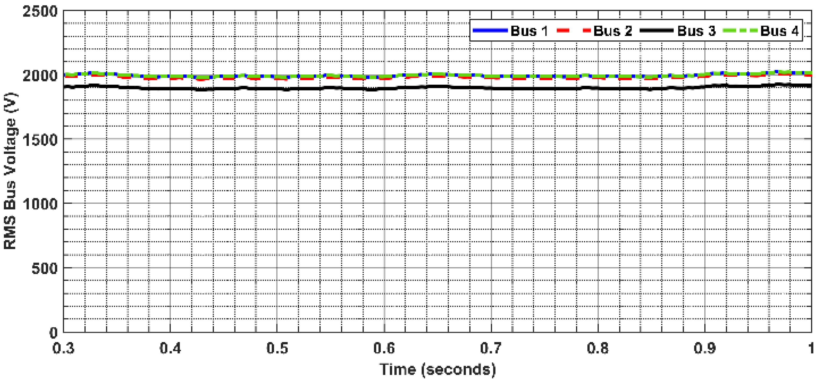
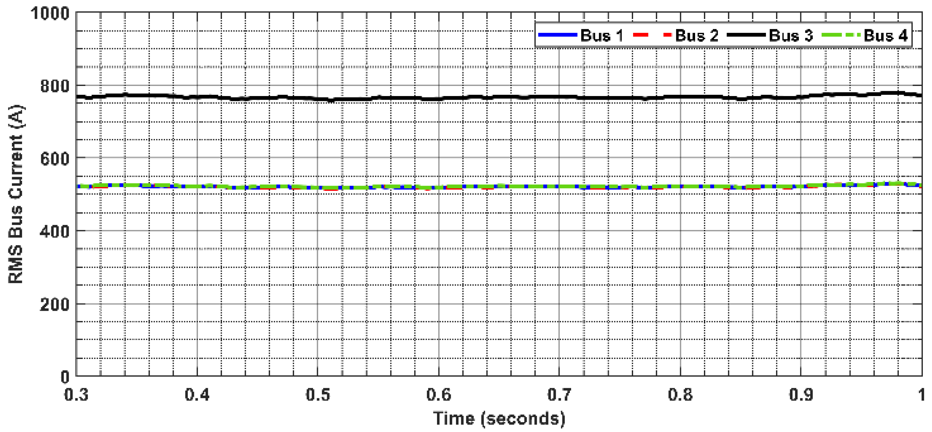
4.1. Normal Operation
4.2. Fault Condition
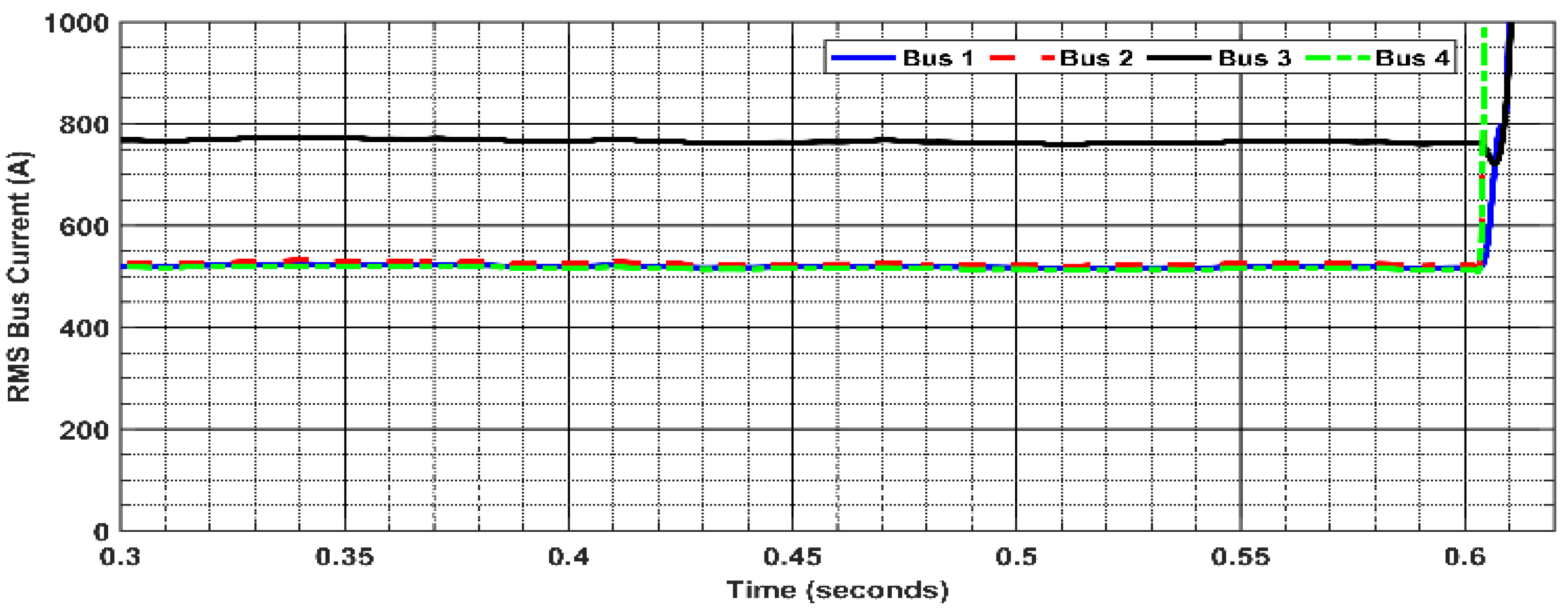
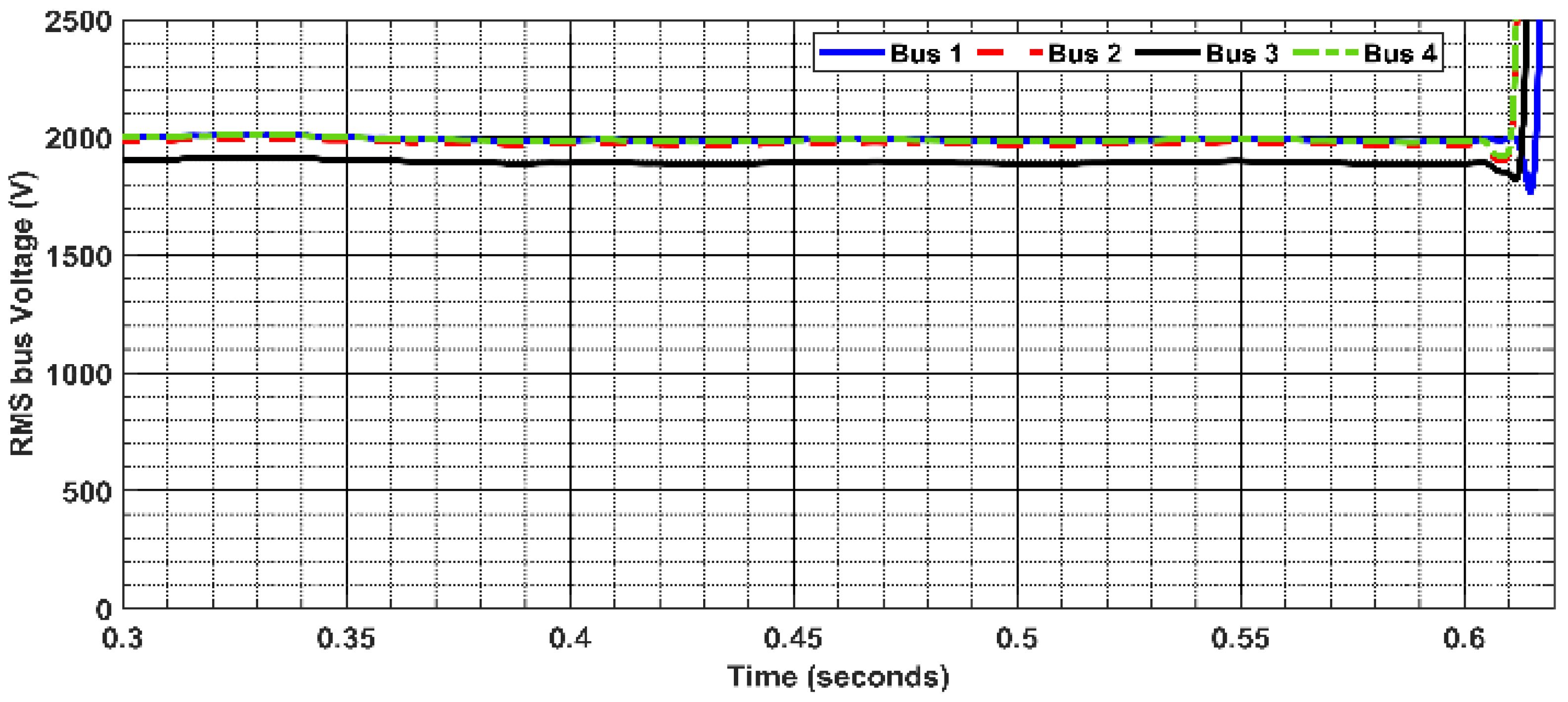
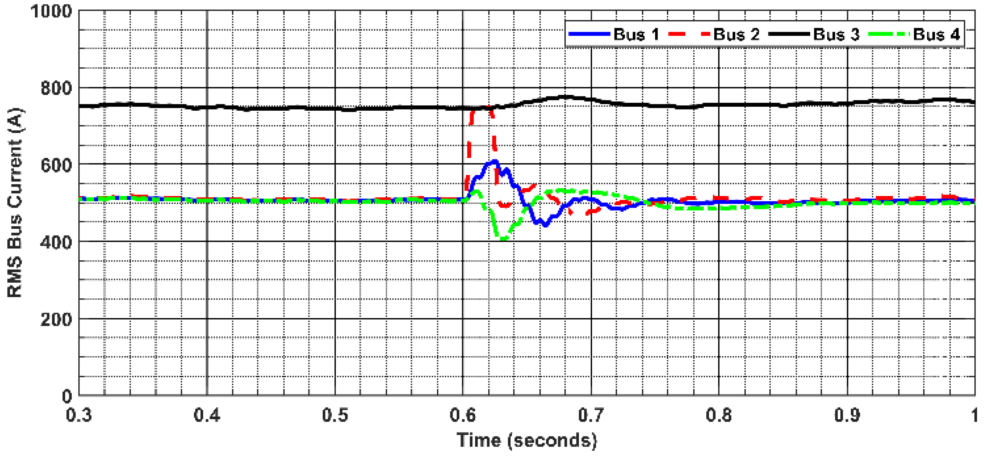
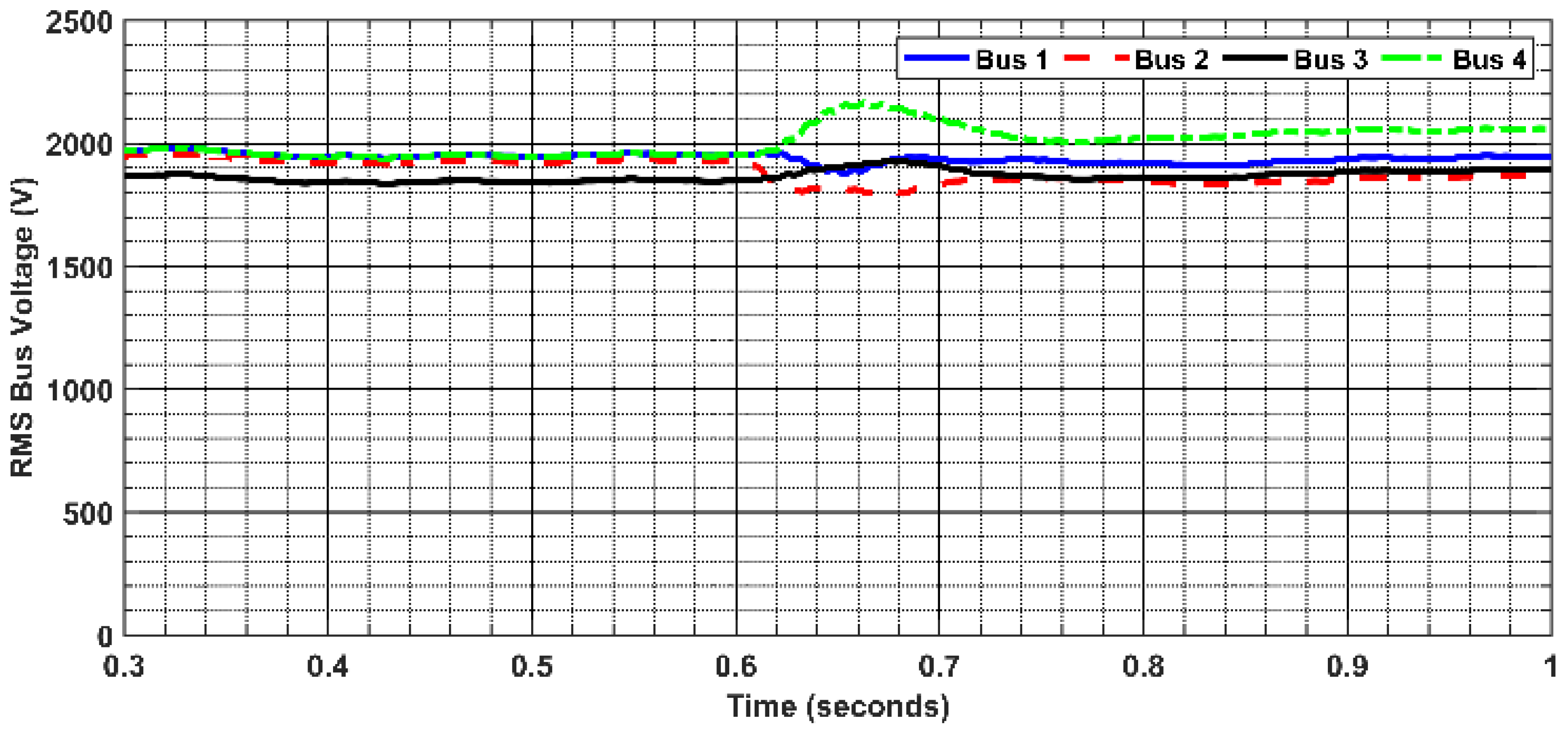
During the faults, the system current and voltage at each bus are deviated from their rated values. Figure 11 and Figure 12 show the currents and voltages at the FREEDM system buses in the presence of the system fault. The applied fault is the single line to ground fault (SLG) at 0.6 s in the line between bus 2 and bus 4, L2–4. From these figures, it can be concluded that the current and voltage at each bus are affected by the fault’s presence. Hence, the protection scheme is essential for this condition to clear the system fault and isolate the faulty element.
4.3. Applying the Proposed Protection Scheme
Different fault cases have been applied to test and evaluate the proposed protection method. A total of four different fault types are SLG, Line–Line (LL), Line–line to ground (LLG), and three-lines to ground (3LG) faults. These faults are applied to different locations of the lines in the FREEDM system at different fault resistance.
There were two fault cases that were selected to be illustrated in detail as an example for testing and verifying the proposed protection scheme. These cases are the SLG fault and LL faults at the line between bus 2 and bus 4, L2–4. After the fault occurred, the system currents and voltages are violated from their rated values. The protection method can detect the faulty line and the fault type by monitoring all the system voltage and currents. Hence, the differential protection method sends a trip signal to open the FIDs which are installed at the two ends of the faulty line to disconnect them from the FREEDM system and restore the normal operation of the system. The DGI sends the tripping signal to the FIDs using Wi-Fi communication and then the information and data are saved in the cyber layer of the IoT platform.
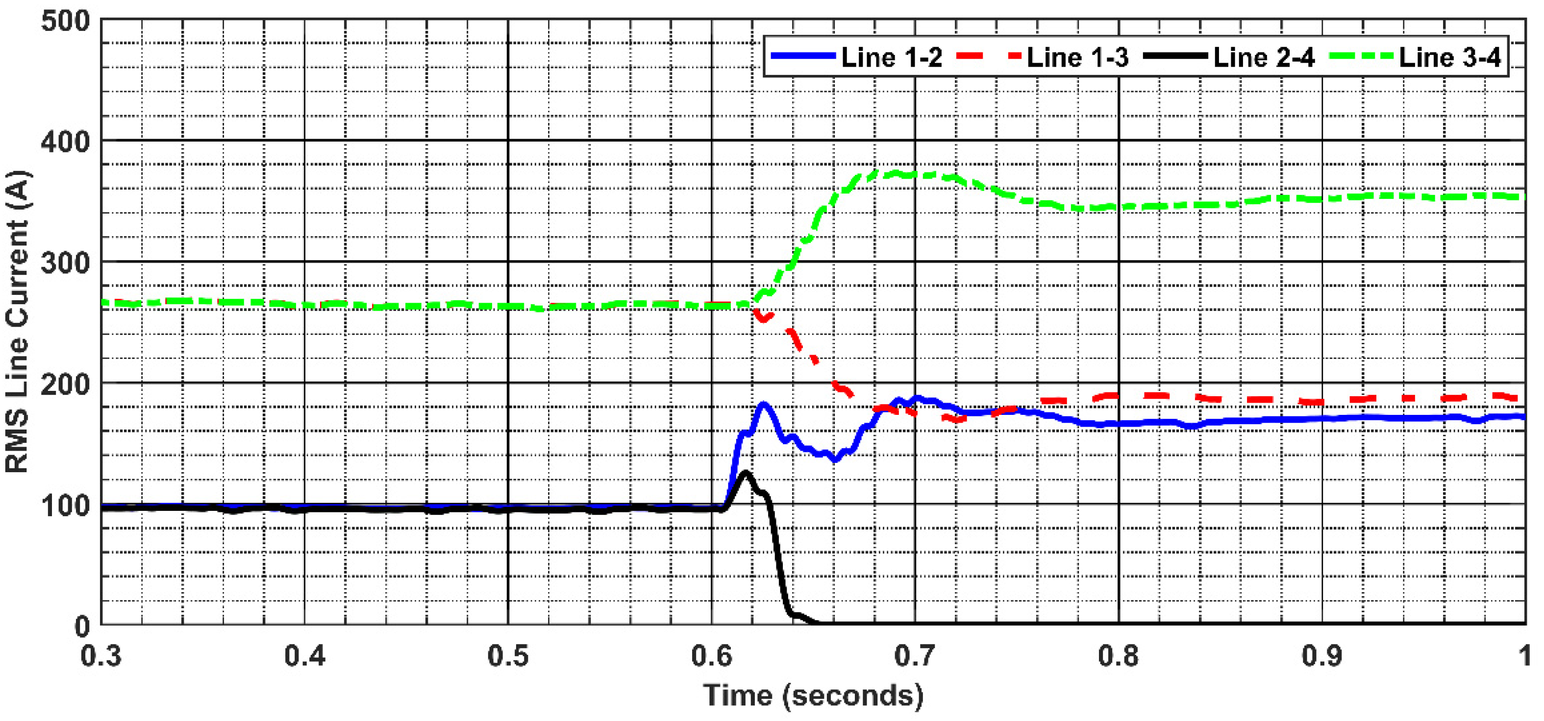
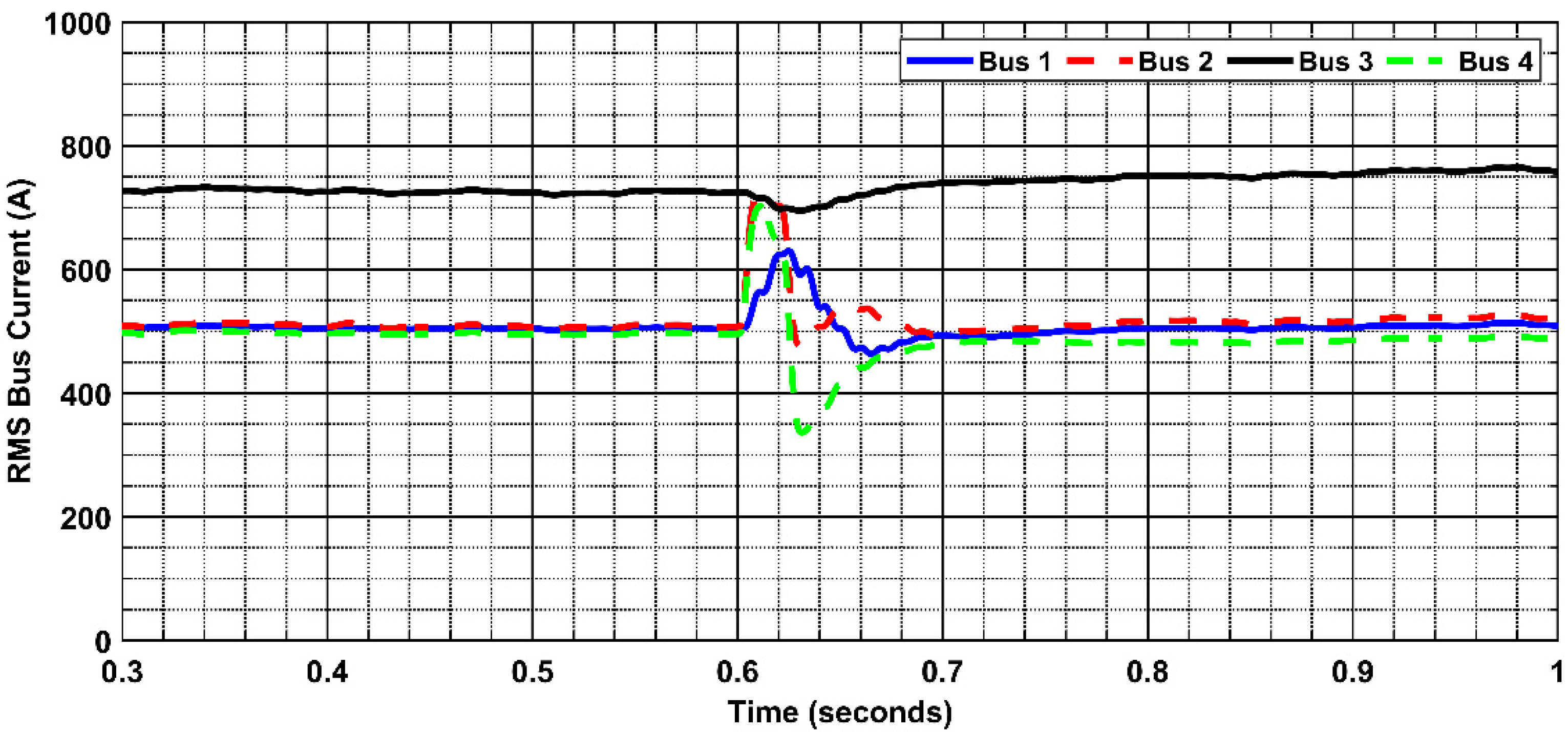
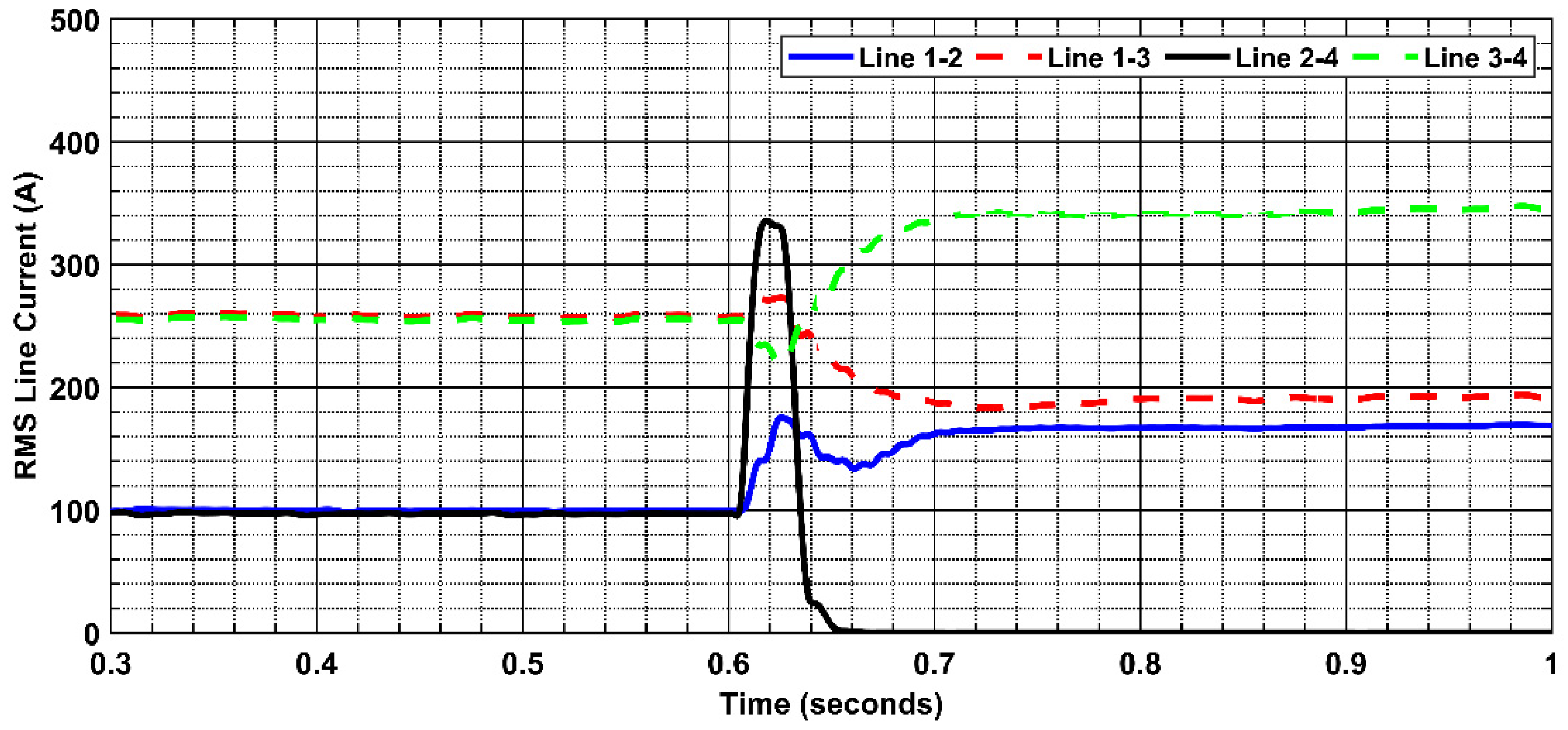
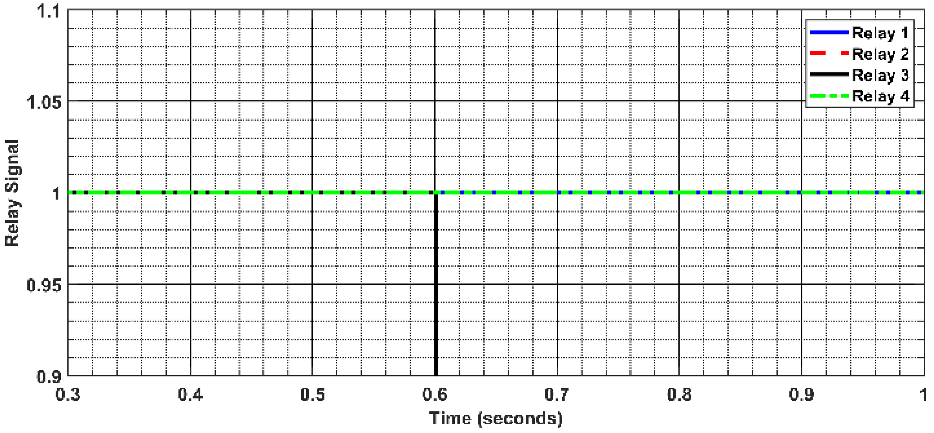
Figure 13 and Figure 14 demonstrate the RMS values of the current and voltage at all the buses of the FREEDM system in case of SLG fault. As observed from these figures, the currents and voltages at all the buses are violated and affected by the fault. After clearing the fault by disconnecting the faulty line using the FIDs, the system is restored to its normal operation. The RMS values of the currents in all the system lines are illustrated in Figure 15. This current in line L2-4 becomes zero after the line is disconnected using the FIDs at the two terminals and all other lines in the system are in service. For the LL fault applied to the line L2–4, the current and voltage at all buses of the system are represented in Figure 16 and Figure 17. The currents in the system lines are illustrated in Figure 18. Figure 19 demonstrates the tripping signal that sends to the FIDs.
Generally, the proposed differential protection method can be applied to detect the faults in the system and restore the normal operation after the fault occurrence. It is based on the differential protection that uses the FIDs in the two ends to disconnect the faulty line. The system measurement data are monitored and processed using the DGI and hence identify the faulty line and clear it. The proposed method depends on the IoT platform with a Wi-Fi protocol for the interlinking between the DGI and all the FIDs in the system. The proposed method achieves an average fault clearing time of 0.001 s.
4.4. Performance Evaluation of the Proposed Differential Protection Scheme
The proposed protection scheme’s performance has been evaluated using three indices of security, dependability, and accuracy as illustrated in Table 2. The dependability index can be expressed as the ratio between the number of detected, corrected faults and the total number of corrected faults, so it calculates the mis-detected faults. It can be improved by increasing the level of relay sensitivity. The security index can be expressed as the ratio between the number of incorrectly detected faults and the total number of faults (correct and incorrect), so it calculates the falsely detected faults. Finally, the accuracy index represents the accuracy of the proposed differential protection scheme to detect the faults and no faults cases. As illustrated in Table 2, the performance of the proposed differential protection scheme is calculated for various fault types (SLG, LL, LLG, and 3LG faults). These fault cases are applied at different line locations and fault resistances. Moreover, these cases are repeated for the four lines; L1–2, L2–3, L3–4, and L1–3. The total number of simulated fault cases is 1943 cases. Based on these fault cases, the overall performance of the proposed protection scheme is efficient and effective. In contrast, the average dependability and security of the protection scheme are 99.25% and 99.401%. Moreover, the protection scheme achieved high accuracy for all the faults, equal to 98.825%.
5. Prototype Design and Implementation
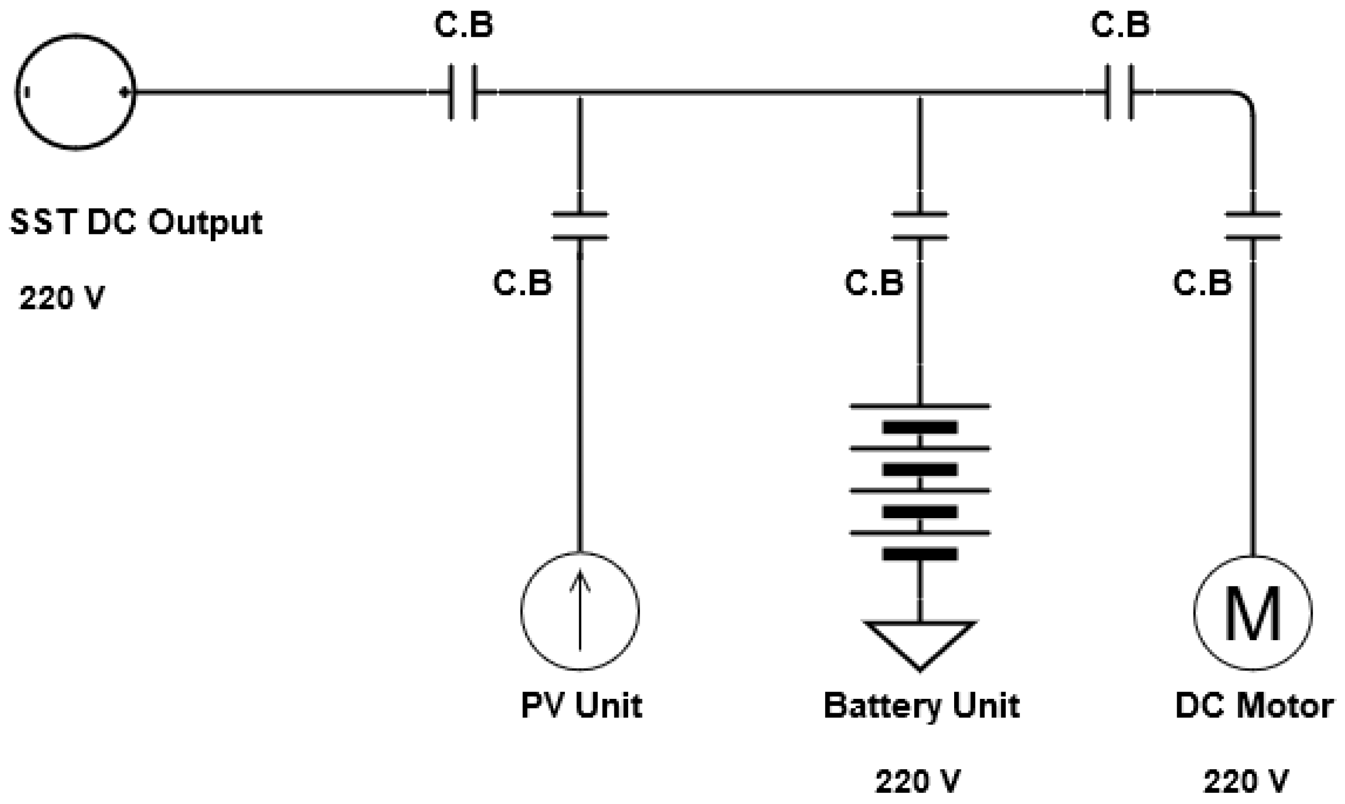
In this section, a prototype of the FREEDM system is designed. Moreover, the operation and the proposed protection scheme have been tested using the FREEDM prototype. The FREEDM prototype is designed as a D.C. grid as shown in Figure 20. It consists of SST as a D.C. source and a P.V. unit as a current source.
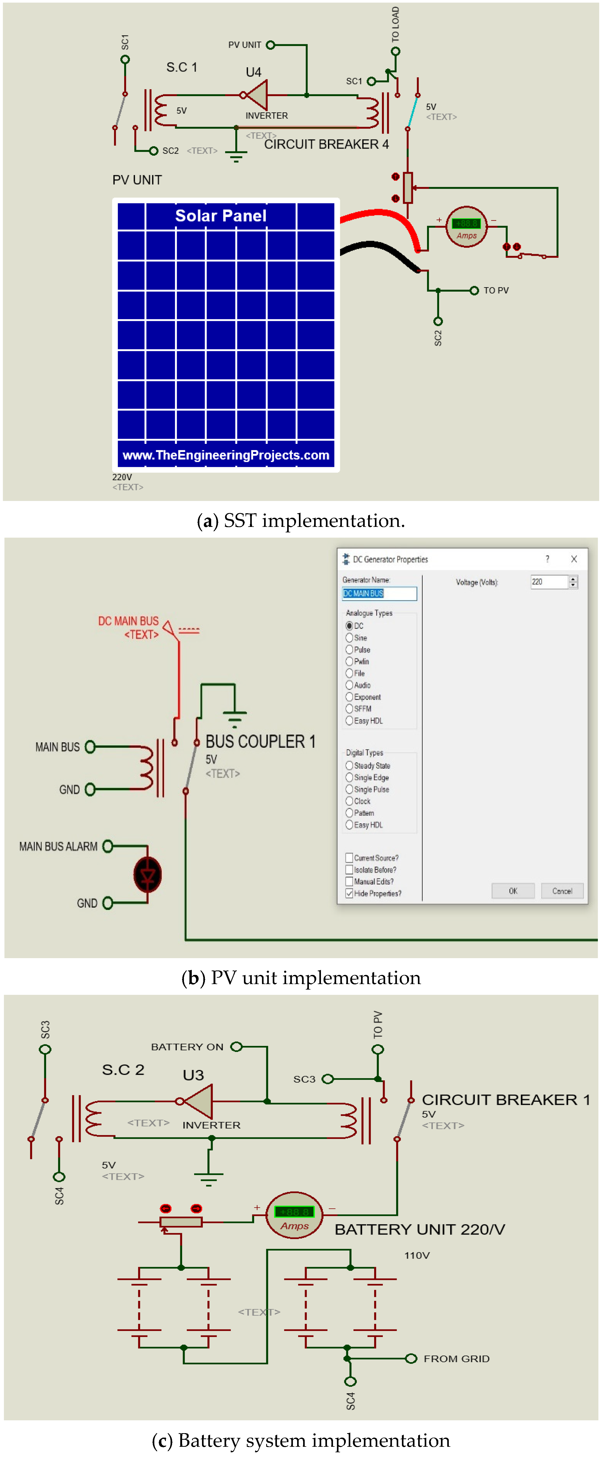
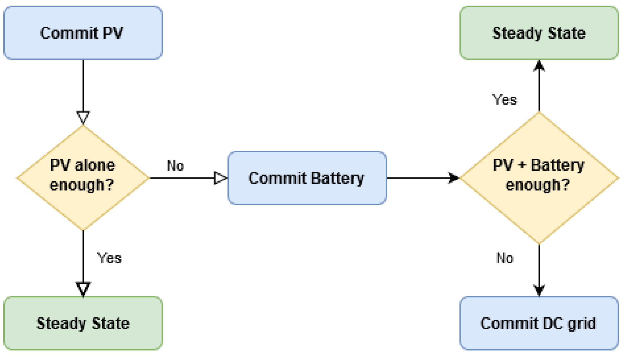
This circuit has been implemented using Proteus software. The A.C. current is converted into D.C. using SST that I implemented in the Proteus simulator as a D.C. generator with 220 V, as shown in Figure 21a. The P.V. unit is implemented as shown in Figure 21b. The battery unit is designed as four 110 V batteries that are connected in series with a potentiometer to simulate its power fluctuations (Figure 21c). The system load power supply is done according to a priority P.V. unit, battery system, and grid. This criterion of using the battery storage with the P.V. system is described in Figure 22.
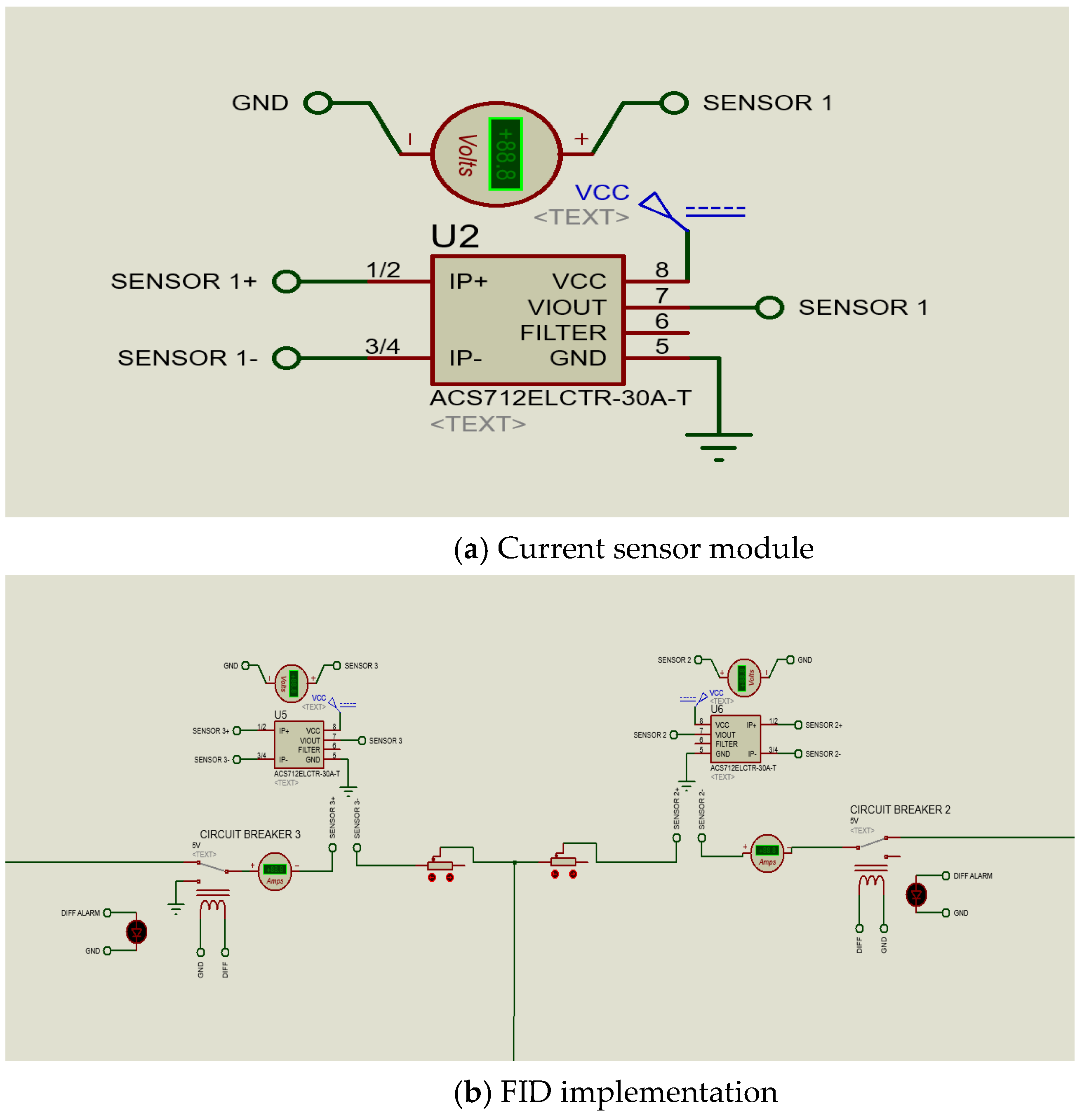
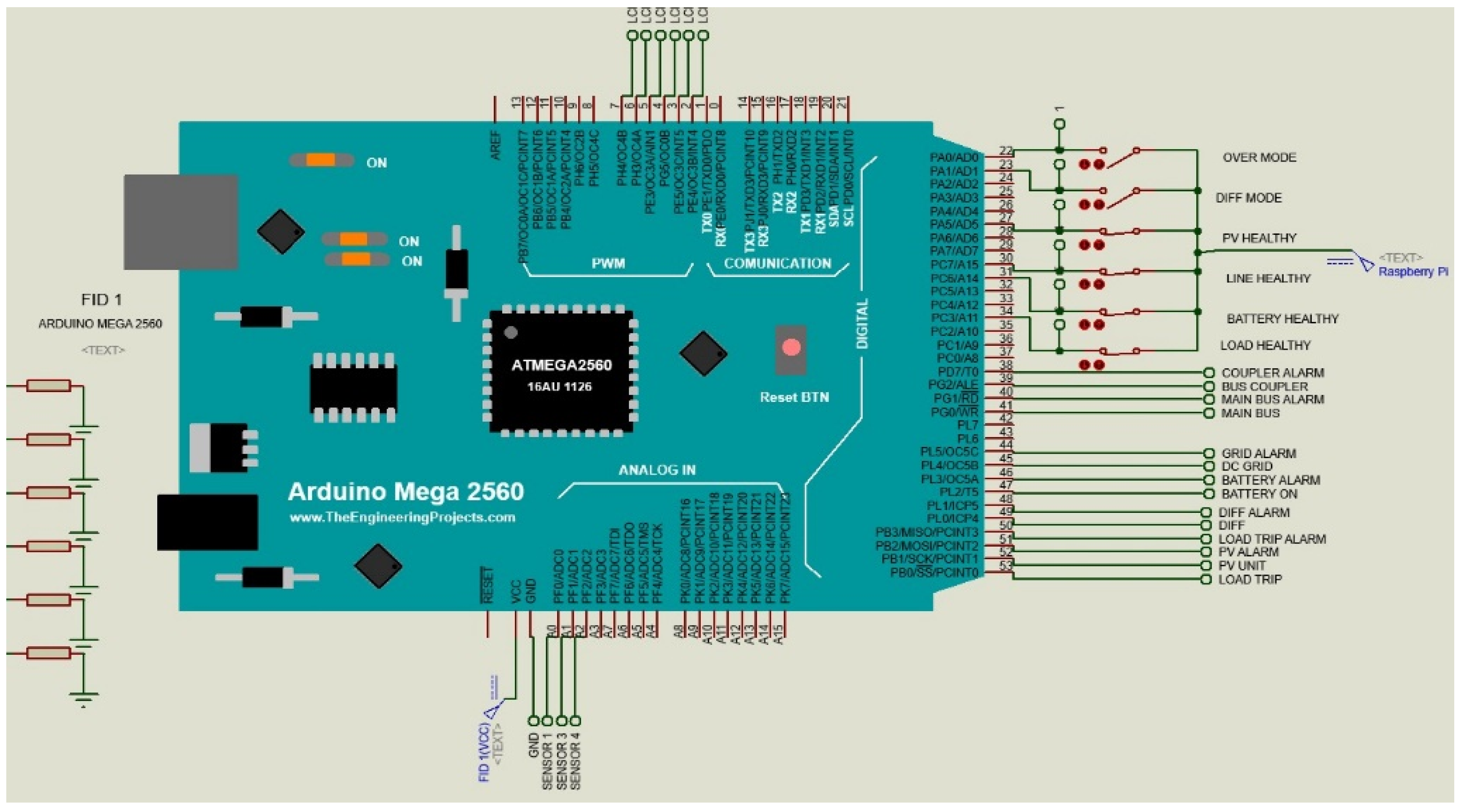
The proposed protection method is implemented using current sensors, FIDs, and differential protection through the Proteus simulator. The current sensor ACS712 is used to measure the current in the FREEDM system as shown in Figure 23a. The output of the current sensors is sent to the FID. The FID is implemented in the program with the Arduino Mega 2560 that is applied to take the signal of the current sensor and then tripping the system or not according to the system’s current measurement as shown in Figure 23b. It is connected to the main DGI in the system that is implemented by a Raspberry PI 3 Model B+ for direct control commands such as enabling and disabling the protection modes.
The schematic diagram of applying the differential protection in the transmission line of the FREEDM system is shown in Figure 24. It can be noticed that the current is measured using the two current sensors at the two terminals of the line. Then, the difference between the two measured currents is compared with a pickup value to indicate the fault condition.
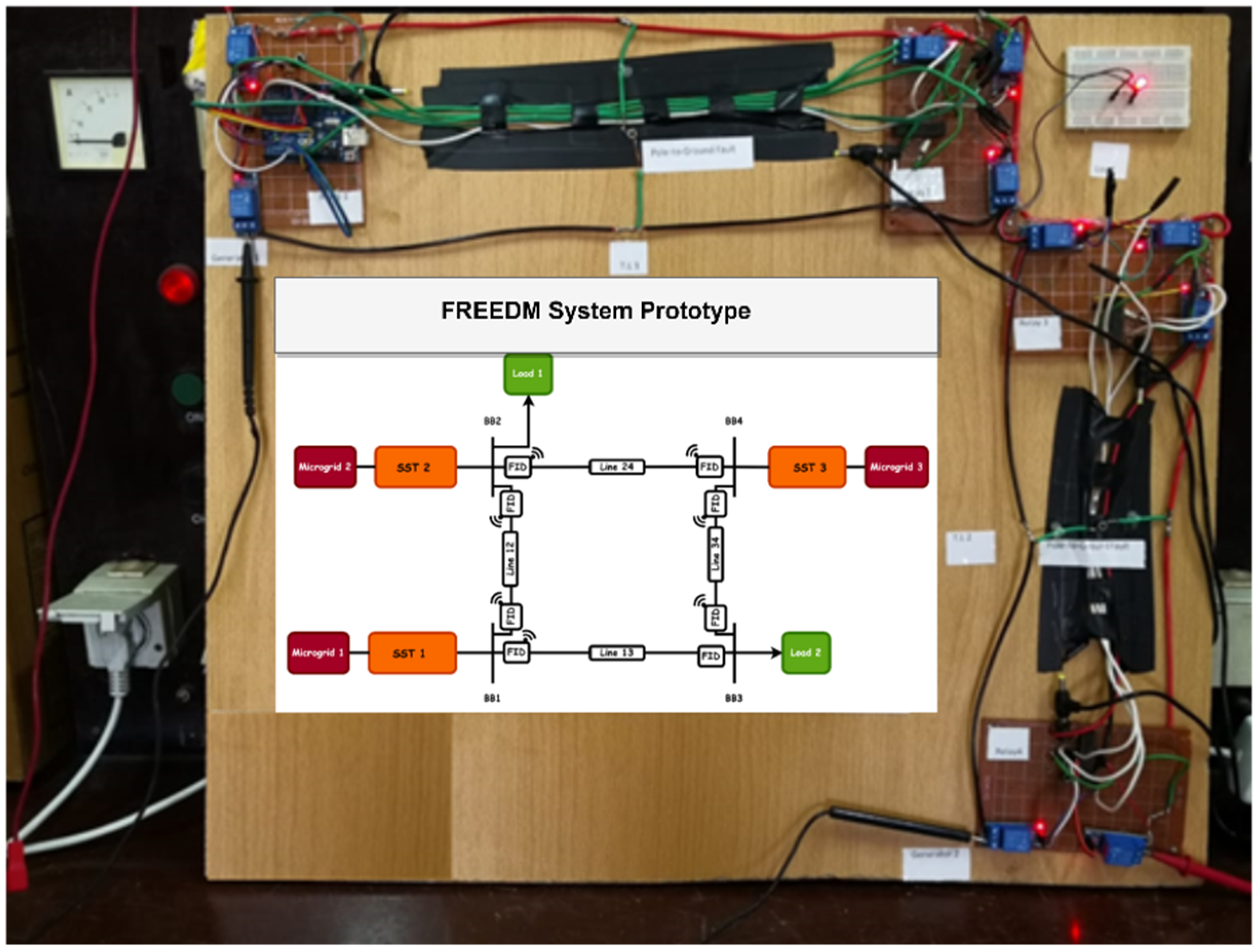
The implementation of the prototype in the laboratory is shown in Figure 25. The system is constructed from the Arduino® Mega 2560, three microcontrollers, relays, and current sensors to control and protect in FREEDM-based M.G. system.
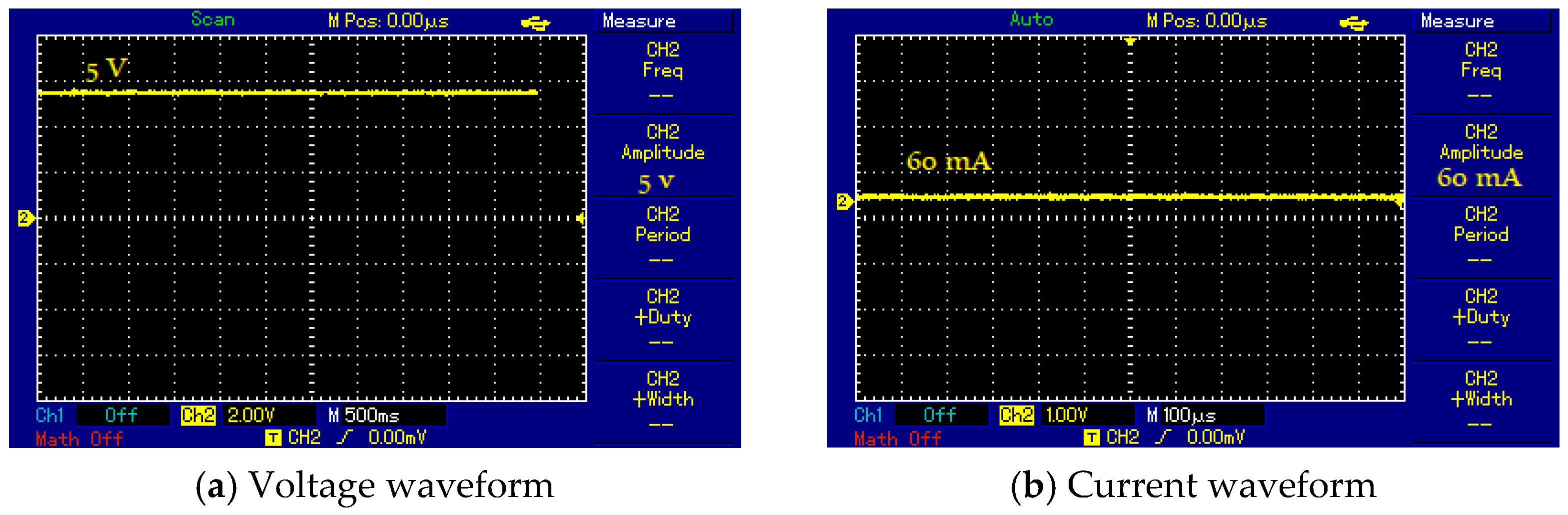
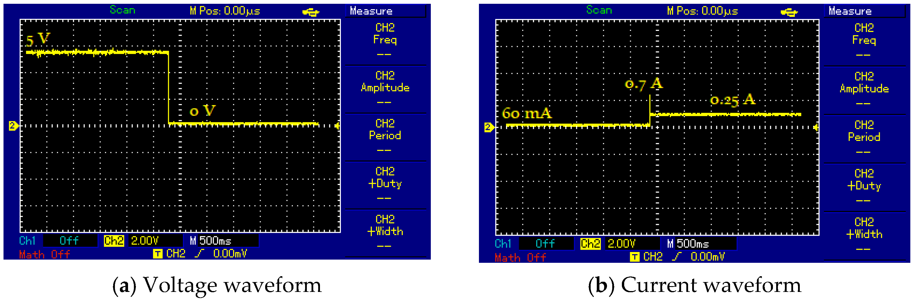
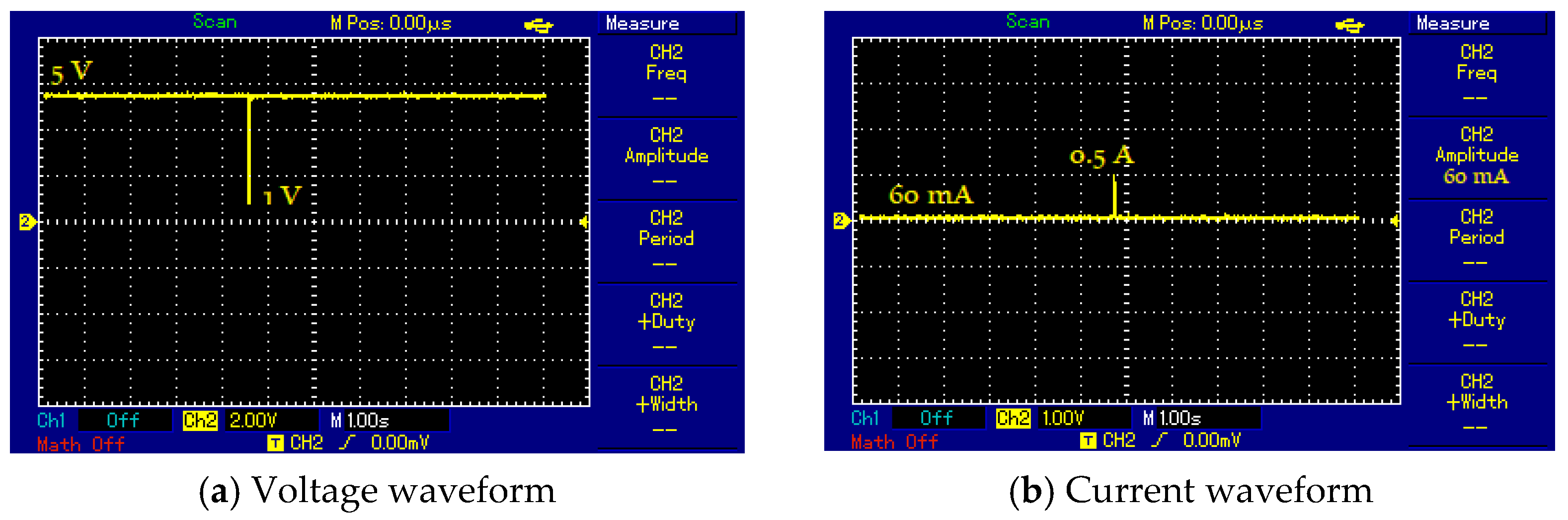
The system voltage and current results at normal operating conditions are shown in Figure 26. The voltage is 5 V and the current is 60 mA. At the fault condition (SLG fault), the voltage and current waveforms are shown in Figure 27. The voltage decreases to zero and the current increases to 0.7 A. However, after applying the proposed protection method, the faulty line is isolated, and the system is retained in a steady-state condition as shown in Figure 28. The results show the effectiveness of the proposed protection method in detecting and isolating the faulty line and retaining the steady-state operation in the system.
6. Conclusions
This paper proposed a protective scheme that is based on differential protection for the FREEDM system. The proposed method applies the IoT communication channel for the interlinking between the two relays in the transmission lines. It has been applied and tested using a hypothetical FREEDM system in MATLAB/Simulink. The results under different operating conditions are obtained: normal operation, fault conditions, and the proposed protection scheme. The results show the proposed protection scheme’s effectiveness and ability to detect and isolate the system fault. Also, a prototype of the FREEDM system is designed and implemented using the Proteus software simulator. The prototype is implemented in the laboratory to verify the applicability of the proposed method. The proposed protection method has the ability to clear the system fault within 0.001 s while achieving 98.825% accuracy for all fault types and different fault resistances. Also, the average dependability and security of the protection scheme are 99.25% and 99.401%, respectively.
Author Contributions
Conceptualization, A.Y.H. and B.E.S.; methodology, A.Y.H.; software, B.E.S.; validation, A.Y.H., M.A.E. and B.E.S.; formal analysis, M.A.E.; investigation, B.E.S.; resources, A.Y.H.; data curation, B.E.S.; writing—original draft preparation, M.A.E.; writing—review and editing, B.E.S.; visualization, M.A.E.; supervision, A.Y.H.; project administration, A.Y.H.; funding acquisition, A.Y.H. All authors have read and agreed to the published version of the manuscript.
Funding
The Deputyship for Research and Innovation, Ministry of Education in Saudi Arabia, through the project number IFP2021-032.
Institutional Review Board Statement
Not applicable.
Informed Consent Statement
Not applicable.
Data Availability Statement
Not applicable.
Acknowledgments
The authors extend their appreciation to the Deputyship for Research and Innovation, Ministry of Education in Saudi Arabia, for funding this research work through the project number IFP2021-032.
Conflicts of Interest
The authors declare no conflict of interest.
Nomenclature
| DES | Distributed energy storage |
| DGI | Distributed grid intelligence |
| DRE | Distributed renewable energy |
| CT | Current transformer |
| FREEDM | Future Renewable Electric Energy Delivery and Management |
| FID | Fault isolation device |
| IEM | Intelligent energy management |
| IoT | Internet of things |
| LAN | Local area network |
| LL | Line to line |
| LLG | Line to line to ground |
| 3LG | Three-lines to ground |
| LVDC | Low voltage D.C |
| MVDC | Medium voltage D.C |
| M.G. | Microgrid |
| MT-HVDC | Multi terminal high voltage direct current |
| PMU | Phasor measurement unit |
| RMS | Root mean square |
| SG | Smart grid |
| SLG | Single line to ground |
| SSCB | Solid-state circuit breakers |
| SST | Solid-state transformer |
| SCADA | Supervisory control and data acquisition |
| WAN | Wide-area network |
References
- Hafez, A.A.; Hatata, A.Y.; Aldl, M.M. Optimal sizing of hybrid renewable energy system via artificial immune system under frequency stability constraints. J. Renew. Sustain. Energy 2019, 11, 015905. [Google Scholar] [CrossRef]
- Wang, J.; Yang, F. Optimal capacity allocation of standalone wind/solar/battery hybrid power system based on improved particle swarm optimisation algorithm. IET Renew. Power Gener. 2013, 7, 443–448. [Google Scholar] [CrossRef]
- Khan, M.; Iqbal, M. Dynamic modeling and simulation of a small wind–fuel cell hybrid energy system. Renew. Energy 2005, 30, 421–439. [Google Scholar] [CrossRef]
- Tailor, J.; Osman, A. Restoration of Fuse-Recloser Coordination in Distribution System with High DG Penetration. In Proceedings of the 2008 IEEE Power and Energy Society General Meeting—Conversion and Delivery of Electrical Energy in the 21st Century, Pittsburgh, PA, USA, 20–24 July 2008; pp. 1–8. [Google Scholar]
- Brahma, S.; Girgis, A. Development of Adaptive Protection Scheme for Distribution Systems with High Penetration of Distributed Generation. IEEE Trans. Power Deliv. 2004, 19, 56–63. [Google Scholar] [CrossRef]
- Plaza, C.; Gil, J.; De Chezelles, F.; Strang, K.A. Distributed Solar Self-Consumption and Blockchain Solar Energy Exchanges on the Public Grid Within an Energy Community. In Proceedings of the 2018 IEEE International Conference on Environment and Electrical Engineering and 2018 IEEE Industrial and Commercial Power Systems Europe (EEEIC/I&CPS Europe), Palermo, Italy, 12–15 June 2018; pp. 1–4. [Google Scholar]
- Brahma, S.; Girgis, A. Microprocessor-based reclosing to coordinate fuse and recloser in a system with high penetration of distributed generation. In Proceedings of the 2002 IEEE Power Engineering Society Winter Meeting, New York, NY, USA, 7–10 November 2003; pp. 453–458. [Google Scholar]
- Yan, B.; Di Somma, M.; Luh, P.B.; Graditi, G. Operation Optimization of Multiple Distributed Energy Systems in an Energy Community. In Proceedings of the 2018 IEEE International Conference on Environment and Electrical Engineering and 2018 IEEE Industrial and Commercial Power Systems Europe (EEEIC/I&CPS Europe), Palermo, Italy, 12–15 June 2018. [Google Scholar] [CrossRef]
- Zhang, X.; Ruiz, H.S.; Geng, J.; Shen, B.; Fu, L.; Zhang, H.; Coombs, T.A. Power Flow Analysis and Optimal Locations of Resistive Type Superconducting Fault Current Limiters. SpringerPlus 2016, 5, 1972. [Google Scholar] [CrossRef] [Green Version]
- Firuzabad, M.; Aminifar, F.; Rahmati, I. Reliability Study of H.V. Substations Equipped with the Fault Current Limiter. IEEE Trans. Power Deliv. 2012, 27, 610–617. [Google Scholar] [CrossRef]
- Razavi, S.; Rahimi, E.; Javadi, M.S.; Nezhad, A.E.; Lotfi, M.; Shafie-khah, M.; Catalão, J.P.S. Impact of Distributed Generation on Protection and Voltage Regulation of Distribution Systems: A review. Renew. Sustain. Energy Rev. 2019, 105, 157–167. [Google Scholar] [CrossRef]
- Mahmud, M.A.; Hossain, M.J.; Pota, H.R. Voltage Variation on Distribution Networks With Distributed Generation: Worst Case Scenario. IEEE Syst. J. 2014, 8, 1096–1103. [Google Scholar] [CrossRef]
- Firouz, Y.; Farhadkhani, S.; Lobry, L.; Vallée, F.; Khakpour, A.; Durieux, O. Numerical Comparison of The Effects of Different Types of Distributed Generation Units on Overcurrent Protection Systems in MV Distribution Grids. Renew. Energy 2014, 69, 271–283. [Google Scholar] [CrossRef]
- Costa, F.B.; Monti, A.; Paiva, S.C. Overcurrent Protection in Distribution Systems With Distributed Generation Based on the Real-Time Boundary Wavelet Transform. IEEE Trans. Power Deliv. 2017, 32, 462–473. [Google Scholar] [CrossRef]
- Gamarra, C.; Guerrero, J. Computational optimization techniques applied to microgrids planning: A review. Renew. Sustain. Energy Rev. 2015, 48, 413–424. [Google Scholar] [CrossRef] [Green Version]
- Hirsch, A.; Parag, Y.; Guerrero, J. Microgrids: A review of technologies, key drivers, and outstanding issues. Renew. Sustain. Energy Rev. 2018, 90, 402–411. [Google Scholar] [CrossRef]
- Jung, J.; Villaran, M. Optimal planning and design of hybrid renewable energy systems for microgrids. Renew. Sustain. Energy Rev. 2017, 75, 180–191. [Google Scholar] [CrossRef]
- Ceglia, F.; Marrasso, E.; Pallotta, G.; Roselli, C.; Sasso, M. The State of the Art of Smart Energy Communities: A Systematic Review of Strengths and Limits. Energies 2022, 15, 3462. [Google Scholar] [CrossRef]
- Zahraee, S.; Assadi, M.K.; Saidur, R. Application of Artificial Intelligence Methods for Hybrid Energy System Optimization. Renew. Sustain. Energy Rev. 2016, 66, 617–630. [Google Scholar] [CrossRef]
- Teimourzadeh, S.; Aminifar, F.; Davarpanah, M.; Shahidehpour, M. Adaptive Protection for Preserving Microgrid Security. IEEE Trans. Smart Grid 2019, 10, 592–600. [Google Scholar] [CrossRef]
- Laaksonen, H.J. Protection Principles for Future Microgrids. IEEE Trans. Power Electron. 2010, 25, 2910–2918. [Google Scholar] [CrossRef]
- Muda, H.; Jena, P. Superimposed Adaptive Sequence Current Based Microgrid Protection: A New Technique. IEEE Trans. Power Deliv. 2017, 32, 757–767. [Google Scholar] [CrossRef]
- Mirsaeidi, S.; Said, D.M.; Mustafa, M.W.; Habibuddin, M.H. A protection strategy for micro-grids based on positive sequence component. IET Renew. Power Gener. 2015, 9, 600–609. [Google Scholar] [CrossRef] [Green Version]
- Duan, J.; Zhang, K.; Cheng, L. A novel method of fault location for single-phase microgrids. IEEE Trans. Smart Grid 2016, 7, 915–925. [Google Scholar] [CrossRef]
- Saleh, S.A.; Ahshan, R.; Abu-Khaizaran, M.S.; Alsayid, B.; Rahman, M.A. Implementing and testing d-q WPT-based digital protection for microgrid systems. IEEE Trans. Ind. Appl. 2014, 50, 2173–2185. [Google Scholar] [CrossRef]
- Kar, S.; Samantaray, S.R. Time-frequency transform-based differential scheme for microgrid protection. IET Gener. Transm. Distrib. 2014, 8, 310–320. [Google Scholar] [CrossRef]
- Gururani, A.; Mohanty, S.R.; Mohanta, J.C. Microgrid protection using Hilbert-Huang transform based-differential scheme. IET Gener. Transm. Distrib. 2016, 10, 3707–3716. [Google Scholar] [CrossRef]
- Abdulwahid, A.H.; Wang, S. A new differential protection scheme for microgrid using Hilbert space based power setting and fuzzy decision processes. In Proceedings of the 2016 IEEE 11th Conference on Industrial Electronics and Applications (ICIEA), Hefei, China, 5–7 June 2016; pp. 6–11. [Google Scholar] [CrossRef]
- Casagrande, E.; Woon, W.L.; Zeineldin, H.H.; Kan’An, N.H. Data mining approach to fault detection for isolated inverter-based microgrids. IET Gener. Transm. Distrib. 2013, 7, 745–754. [Google Scholar] [CrossRef]
- Casagrande, E.; Woon, W.L.; Zeineldin, H.H.; Svetinovic, D. A Differential Sequence Component Protection Scheme for Microgrids With Inverter-Based Distributed Generators. IEEE Trans. Smart Grid 2014, 5, 29–37. [Google Scholar] [CrossRef]
- Mishra, D.P.; Samantaray, S.R.; Joos, G. A combined wavelet and data-mining based intelligent protection scheme for microgrid. IEEE Trans. Smart Grid 2016, 7, 2295–2304. [Google Scholar] [CrossRef]
- Kar, S.; Samantaray, S.R.; Zadeh, M.D. Data-mining model based intelligent differential microgrid protection scheme. IEEE Syst. J. 2017, 11, 1161–1169. [Google Scholar] [CrossRef]
- Lei, L.; Wang, C.; Gao, J.; Zhao, J.; Wang, X. A Protection Method Based on Feature Cosine and Differential Scheme for Microgrid. Math. Probl. Eng. 2019, 2019, 7248072. [Google Scholar] [CrossRef] [Green Version]
- Piesciorovsky, E.C.; Schulz, N.N. Comparison of Programmable Logic and Setting Group Methods for adaptive overcurrent protection in microgrids. Electr. Power Syst. Res. 2017, 151, 273–282. [Google Scholar] [CrossRef]
- Eladl, A.A.; Saeed, M.A.; Sedhom, B.E.; Guerrero, J.M. IoT Technology-Based Protection Scheme for MT-HVDC Transmission Grids With Restoration Algorithm Using Support Vector Machine. IEEE Access 2021, 9, 86268–86284. [Google Scholar] [CrossRef]
- Swathika, O.V.G.; Hemamalini, S. Prims-Aided Dijkstra Algorithm for Adaptive Protection in Microgrids. IEEE J. Emerg. Sel Top. Power Electron. 2016, 4, 1279–1286. [Google Scholar] [CrossRef]
- Coffele, F.; Booth, C.; Dysko, A. An Adaptive Overcurrent Protection Scheme for Distribution Networks. IEEE Trans. Power Deliv. 2015, 30, 561–568. [Google Scholar] [CrossRef] [Green Version]
- Bukhari, S.B.; Haider, R.; Zaman, M.S.; Oh, Y.; Cho, G.; Kim, C. An interval type-2 fuzzy logic-based strategy for microgrid protection. Int. J. Electr. Power Energy Syst. 2018, 98, 209–218. [Google Scholar] [CrossRef]
- Li, X.; Dysko, A.; Burt, G.M. Traveling Wave-Based Protection Scheme for Inverter-Dominated Microgrid Using Mathematical Morphology. IEEE Trans. Smart Grid 2014, 5, 2211–2218. [Google Scholar] [CrossRef] [Green Version]
- Yu, J.J.Q.; Hou, Y.; Lam, A.Y.S.; Li, V.O.K. Intelligent Fault Detection Scheme for Microgrids With Wavelet-Based Deep Neural Networks. IEEE Trans. Smart Grid 2017, 10, 1694–1703. [Google Scholar] [CrossRef]
- Soleimanisardoo, A.; Karegar, H.K.; Zeineldin, H.H. Differential Frequency Protection Scheme Based on Off-Nominal Frequency Injections for Inverter-Based Islanded Microgrids. IEEE Trans. Smart Grid 2019, 10, 2107–2114. [Google Scholar] [CrossRef]
- Hatata, A.Y.; Essa, M.A.; Sedhom, B.E. Adaptive Protection Scheme for FREEDM Microgrid Based on Convolutional Neural Network and Gorilla Troops Optimization Technique. IEEE Access 2022, 10, 55583–55601. [Google Scholar] [CrossRef]
- Aboelezz, A.; Sedhom, B.; El-Saadawi, M. Intelligent distance relay based on IEC 61850 for D.C. zonal shipboard microgrid protection. In Proceedings of the 2nd International Conference on Power, Control and Computing Technologies (ICPC2T), Raipur, India, 1–3 March 2022. [Google Scholar]
- Aboelezz, A.; Sedhom, B.; El-Saadawi, M. Pilot distance protection scheme for D.C. zonal shipboard microgrid. In Proceedings of the 4th International Symposium on Advanced Electrical and Communication Technologies (ISAECT), Alkhobar, Saudi Arabia, 6–8 December 2021. [Google Scholar]
- Sharma, N. Novel Directional Protection Scheme for the FREEDM Smart Grid System. Master′s Thesis, Arizona State University, Tempe, AZ, USA, August 2015. [Google Scholar]
- Alex, Q.H.; Mariesa, L.C.; Gerald, T.H.; Jim, P.Z.; Steiner, J.D. The future renewable electric energy delivery and management (FREEDM) system: The energy internet. Proc. IEEE 2011, 99, 133–148. [Google Scholar]
- Romero, J.G.; Cisneros, R.; Khan, M.T.; Mendez, C.F. Adaptive observer—Based tracking controller designs for a distributed energy storage. IFAC 2018, 51, 615–620. [Google Scholar] [CrossRef]
- Adetokunbo, A. Intelligent Home Energy Management Systems for Distributed Renewable Generators, Dispatchable Residential Loads and Distributed Energy Storage Devices. Master’s Thesis, University of Michigan-Dearbor, Dearborn, MI, USA, 2017. [Google Scholar]
- Lasantha, M.; Manoj, D.; Inam, N.; James, C. Role of fault ride—Through strategies for power grids with 100% power electronic—Interfaced distributed renewable energy resources. WIREs Energy Environ. 2018, 7, e292. [Google Scholar]
- Langarizadeh, A.; Hasheminejad, S. A new differential algorithm based on S-transform for the micro-grid protection. Electr. Power Syst. Res. 2021, 202, 107590. [Google Scholar] [CrossRef]
- Zhou, C.; Zou, G.; Du, X.; Zang, L. Adaptive current differential protection for active distribution network considering time synchronization error. Int. J. Electr. Power Energy Syst. 2022, 140, 108085. [Google Scholar] [CrossRef]
- Adewole, A.; Rajapakse, A.; Ouellette, D.; Forsyth, P. Protection of active distribution networks incorporating microgrids with multi-technology distributed energy resources. Electr. Power Syst. Res. 2022, 202, 107575. [Google Scholar] [CrossRef]
- Nikolaidias, C.; Michaloudis, G.; Tsimtsios, A.; Tzelepis, D.; Booth, C. A coordinated multi-element current differential protection scheme for active distribution systems. IEEE Trans. Power Deliv. 2022. [Google Scholar] [CrossRef]
- Saxena, A.; Sharma, N.; Samantaray, S. An enhanced differential protection scheme for LVDC microgrid. IEEE J. Emerg. Sel. Top. Power Electron. 2022, 10, 2114–2125. [Google Scholar] [CrossRef]
- Zhou, C.; Zou, G.; Zang, L.; Du, X. Current Differential Protection for Active Distribution Networks Based on Improved Fault Data Self-Synchronization Method. IEEE Trans. Smart Grid 2022, 13, 166–178. [Google Scholar] [CrossRef]
- Rao, G.; Jena, P. Fault detection in D.C. microgrid based on the resistance estimation. IEEE Syst. J. 2022, 16, 1009–1020. [Google Scholar] [CrossRef]
- Sharma, N.; Saxena, A.; Samantaray, S. An intelligent differential protection scheme for D.C. microgrid. In Proceedings of the 9th IEEE International Conference on Power Systems (ICPS), Kharagpur, India, 16–18 December 2021. [Google Scholar]
- Dashtdar, M.; Rubanenko, O.; Danylchenko, D.; Sadegh, S.; Sharma, V.; Baiai, M. Protection of D.C. microgrids based on differential method by fuzzy systems. In Proceedings of the IEEE 2nd KhPI Week on Advanced Technology (KhPIWeek), Kharkiv, Ukraine, 13–17 September 2021. [Google Scholar]
- Barnes, A.; Mate, A. Dynamic state estimation for radial microgrid protection. In Proceedings of the IEEE/IAS 57th Industrial and Commercial Power Systems Technical Conference (I&CPS), Las Vegas, NV, USA, 27–30 April 2021. [Google Scholar]
- Zhang, W.; Zhang, H.; Zhi, N. Novel protection scheme for ring D.C. microgrids. In Proceedings of the IEEE 12th Energy Conversion Congress & Exposition—Asia (ECCE-Asia), Singapore, 24–27 May 2021. [Google Scholar]
- Asuhaimi, F.A.; Bu, S.; Nadas, J.P.B.; Imran, M.A. Delay-Aware Energy-Efficient Joint Power Control and Mode Selection in Device-to-Device Communications for FREEDM Systems in Smart Grids. IEEE Access 2019, 7, 87369–87381. [Google Scholar] [CrossRef]
- Ronan, E.; Sudhoff, S.; Glover, S.; Galloway, D. A power electronic-based distribution transformer. IEEE Trans. Power Deliv. 2002, 17, 537–543. [Google Scholar] [CrossRef]
- Falcones, S.; Mao, X.; Ayyanar, R. Topology comparison for Solid State Transformer implementation. In Proceedings of the Power and Energy Society General Meeting, Minneapolis, MN, USA, 25–29 July 2010. [Google Scholar]
- Hossain, M.; Leevongwat, I.; Rastgoufard, P. Design and testing of a bus differential protection scheme using partial operating current (POC) algorithm. Electr. Power Syst. Res. 2018, 157, 29–38. [Google Scholar] [CrossRef]
Figure 1.
The interface of DESs, DRE sources, and loads in FREEDM.

Figure 2.
FREEDM concept model.

Figure 3.
Stages of the SST.

Figure 4.
Current differential protection scheme for line protection.

Figure 5.
Dual slop restraint characteristics.

Figure 6.
Flowchart of the proposed protection method.

Figure 7.
Schematic diagram of the proposed communication platform.

Figure 8.
FREEDM system structure.

Figure 9.
Bus voltages at normal operating conditions.

Figure 10.
Bus currents at normal operating conditions.

Figure 11.
Bus currents at the fault condition.

Figure 12.
Bus voltages at the fault condition.

Figure 13.
Bus currents after applying the proposed protection scheme for the SLG fault.

Figure 14.
Bus voltages after applying the proposed protection scheme for the SLG fault.

Figure 15.
Line currents after applying the proposed protection scheme for the SLG fault.

Figure 16.
Bus currents after applying the proposed protection scheme for the LL fault.

Figure 17.
Bus voltages after applying the proposed protection scheme for the LL fault.

Figure 18.
Line currents after applying the proposed protection scheme for the LL fault.

Figure 19.
Tripping signal for the relays.

Figure 20.
Schematic diagram of the FREEDM prototype.

Figure 21.
FREEDM system implementation in the Proteus simulator.

Figure 22.
Load supply criteria.

Figure 23.
Protection system devices implementation.

Figure 24.
Schematic diagram of the differential protection for FREEDM prototype.

Figure 25.
Prototype of the FREEDM protection in the laboratory.

Figure 26.
Results of the voltage and current waveforms at normal operating conditions.

Figure 27.
Results of the voltage and current waveforms at SLG fault conditions.

Figure 28.
Results of the voltage and current waveforms after applying for the proposed protection.


Table 1.
Parameters of the FREEDM network.
| Item | Value |
|---|---|
| Line length | 1000 m |
| Line inductance | 1.8674 mH |
| Line resistance | 0.0254 Ω |
| Rated voltage of system | 380 V |
| Frequency of microgrids | 50 Hz |
| Rated voltage of microgrids | 6.6 kV (L-L) |
| Active load | 100 kW |
| Reactive load | 10 kVAr |
Table 2.
Dependability, security, and accuracy of the proposed protection scheme based the FEEDM system.
Table 2.
Dependability, security, and accuracy of the proposed protection scheme based the FEEDM system.
| Fault Types | Number of Cases | Dependability | Security | Accuracy |
|---|---|---|---|---|
| SLG | 621 | 99.103 | 98.821 | 97.371 |
| LL | 621 | 100 | 99.643 | 99.126 |
| LLG | 621 | 98.17 | 99.14 | 97.882 |
| 3L | 80 | 100 | 100 | 100 |
| Overall | 1943 | 99.25 | 99.401 | 98.825 |
Publisher’s Note: MDPI stays neutral with regard to jurisdictional claims in published maps and institutional affiliations. |
© 2022 by the authors. Licensee MDPI, Basel, Switzerland. This article is an open access article distributed under the terms and conditions of the Creative Commons Attribution (CC BY) license (https://creativecommons.org/licenses/by/4.0/).
Share and Cite
MDPI and ACS Style
Hatata, A.Y.; Essa, M.A.; Sedhom, B.E. Implementation and Design of FREEDM System Differential Protection Method Based on Internet of Things. Energies 2022, 15, 5754. https://doi.org/10.3390/en15155754
AMA Style
Hatata AY, Essa MA, Sedhom BE. Implementation and Design of FREEDM System Differential Protection Method Based on Internet of Things. Energies. 2022; 15(15):5754. https://doi.org/10.3390/en15155754
Chicago/Turabian StyleHatata, Ahmed Y., Mohamed A. Essa, and Bishoy E. Sedhom. 2022. "Implementation and Design of FREEDM System Differential Protection Method Based on Internet of Things" Energies 15, no. 15: 5754. https://doi.org/10.3390/en15155754
Note that from the first issue of 2016, this journal uses article numbers instead of page numbers. See further details here.