
Design and Control of a Multi-Axis Servo Motion Chair System Based on a Microcontroller


1
Aeronautical System Research Division, Simulation System Section, National Chung-Shan Institute of Science and Technology, Taichung 407, Taiwan
2
Department of Mechanical Engineering, National Chin-Yi University of Technology, Taichung 411, Taiwan
3
Department of Intelligent Automation Engineering, National Taipei University of Technology, Taipei 106, Taiwan
*
Author to whom correspondence should be addressed.
Energies 2022, 15(12), 4401; https://doi.org/10.3390/en15124401
Submission received: 17 May 2022
/
Revised: 10 June 2022
/
Accepted: 14 June 2022
/
Published: 16 June 2022
(This article belongs to the Special Issue Design and Control of Electrical Motor Drives II)
Abstract
:In this study, we present a design and a control based on a microcontroller for a multi-axis servo motion chair. The main purpose was to provide the pilot with the tactile sensations required by the human body to increase the immersion of simulation training. With high system control reliability and multi-functionality, the proposed architecture was built with an effective split of the control tasks involved between a master controller and five slave drivers. To assess the effectiveness of the proposed control system, RS485 and RS232 communication transmission interfaces were provided for the control system to obtain related movement information. The performance of the motion chair was assessed through various experimental tests. The results confirmed that the proposed multi-core system-on-chip microcontroller (MCU) with independent communication and real-time control subsystems was feasible to control a multi-axis servo motion chair system.
1. Introduction
Due to the scarcity of energy, the increase in its cost and its wide range of applications, the use of other types of renewable resources for power generation is a primary concern. One of the renewable energy sources used for power generation is solar energy. A solar tracking system increases the efficiency of solar panels by converting them into a source of electricity [1]. The way sunlight is detected can be improved by using the system so that more electrical energy can be collected. Climate change causes changes in sunlight availability, leading to higher temperatures; this can affect the performance efficiency of PV modules. Sun-tracking technology has emerged to help photovoltaic systems capture maximum solar irradiance, thereby increasing the power output. To avoid human error, the concept of the Internet of Things (IoT) has been incorporated. The ability to transmit data over a network has no requirement of human–human or human–machine interactions. This is an effective competitive solution for an evolving technology using solar power [2]. It can also provide a power source for the simulators used for pilot training.
The training period for pilots around the world is usually lengthy. Hence, flight training simulators are in high demand and are an indispensable tool for flight training. As mentioned in [3], a motion simulation system with comprehensive high fidelity was first established in the 1950s. In 1954, the General Precision Equipment Corporation of the United States developed a motion simulation system that could perform three-degree pitch, roll and yaw. Through continuous improvement, the system achieved 10-degree pitch, roll and yaw [4]. Stewart proposed a six-axis parallel motion platform structure in 1965 [5]. Subsequently, a hydraulic drive has been used in civil aviation simulators with six degrees of freedom to control the movement of each axis. The basic framework design of a simulator is as shown in [6]. However, the sense of contact of the human body is different from the sense of space produced by a platform with six degrees of freedom. Several researchers have investigated and improved this framework, including a discussion identifying the relationship of six-axis motion with each actuator based on kinematics [7,8] and a discussion of how compensating for the perturbation rate of the load improves positioning accuracy [9].
The gravity pressure on human bodies can be simulated by contact with an exercise chair. In the study by Gum [10], a test of the research model showed that there was a time delay between the applied forces and the perceptions of various mechanisms. The results showed that pressure-sensing structures and intramuscular senses applied forces at a faster rate than the vestibular system. Cardullo et al. [11] engaged with this type of chair design, hoping to stimulate a haptic system with the chair. The objective was that the seat could independently produce the expected changes in skeletal posture, mimic the areas associated with the changes in skin contact and reflect the changes in muscle pressure gradients. In addition, the seat was designed to simulate the effects of acceleration variation. The chair included two airbags, which led to the seat and back cushions. Consequently, a control approach was utilized to independently actuate the airbags to manipulate the height, position and shape of the supporting surface. In the design, the tactile feel of bodies changed with the airbags. In [12], Berger et al. presented a study on perceptions and visual sensations. The results demonstrated that perception had qualitative matching in the magnitude of visual acceleration that could enhance the information transfer between them. The findings displayed that the use of the visual effect in building a motion notification of an early warning algorithm could increase the linear acceleration motion effect of the simulator. Bruschetta et al. [13] utilized a Stewart platform with the seat as a motion platform. Specifically, they produced the sensation of sustained acceleration with a low frequency by placing eight inflators on the chair. Four were equipped on the seatback, two were placed on the seat pan and one was placed on either side of the seatbelt. The sense of restraint exerted by the inflatable device through the seatbelt created a sense of sustained low frequency acceleration after the device was inflated. In [14], Toda et al. designed a single degree of freedom seat simulator to examine the fatigue that bodies perceive after a long period of driving. The simulator consisted of a single degree of freedom chair and a steering wheel as well as visual effects; tests for physical fatigue were performed by adjusting the impact axis on the back. In [15], Ishii et al. developed a dual DOF (roll and pitch axes) seat where they used the rotation in the seat roll and the shock axis to investigate whether self-driving cars could predict the position and behavior of other cars after few seconds. In [16], a vibration table was designed that consisted of a linear servo motor to test the perceived riding comfort of drivers. Berthoz et al. [17] investigated different motion scaling factors in a driving simulator. With motion feedback, the participants drove more carefully and had better control of the cars. As a result, they could better predict the dynamic behavior of the car and were not surprised when the car crashed. Greatly reduced or absent motion cues significantly reduced the drivability.
Most simulators are designed based on the Stewart platform with a 6 DOF structure [18,19,20], which simulates and presents the global motion of 6 DOF. However, the Stewart platform cannot offer the kinematic sensations pilots experience whilst flying. Therefore, the purpose of this work was to design a four DOF chair system for motion simulation, providing pilots with tactile sensations related to motion. The physical sensations experienced by the pilots during flight were converted into data. This enabled the pilots to experience relevant haptic sensations and ensure that the flight simulation was a more immersive experience. The design and control of the chair were based on mathematical modeling. A kinematic model was used to describe the relationship between the motion position of the simulator in space and the rotation angle of each joint via a structural analysis; the limitations of the motion space were then observed. The seat plate assembly was composed of a heave shaft and a roll shaft. The back pad assembly included a swing axis and a surge axis. The seat height structure had an adjustable vertical structure for the entire seat. As each component had a single DOF motion, we referred to the methods used in [21,22,23] to determine the kinematic model based on the geometric relationship between the links. In contrast, inverse kinematics involves obtaining displacements or angles of each joint based on the reverse engineering of the moving position of a simulator and its attitude in space.
It is challenging to train pilots using the Stewart platform as a simulator, especially for a sense of gravity with short distance movements. We designed a chair with four degrees of freedom as the gravitational motion required for flight. An electromechanical integrated control architecture combined with an MCU was proposed. Motion simulation helps to achieve the highly sensitive human perception of motion through platform motion and enhances the effect of virtual reality. The whole controlled system comprised a dual-core master controller combining a C2000 Texas Instruments (TI) MCU for real-time control tasks with an Arm Cortex-M3 processor for communication purposes. To the best of our knowledge, the above-mentioned ideas were original as they have not been presented in previously published papers [1,2,3,4,5,6,7,8,9,10,11,12,13,14,15,16,17,18,19,20,21,22,23,24].
The rest of the article is organized as follows. Section 2 introduces the system architecture and the control strategy process is explained. Section 3 discusses the kinematics of the motion chair system. The implemented system and the experimental results are shown in Section 4 and Section 5, respectively, and Section 6 presents the conclusions.
2. System Architecture
2.1. System Overview
The mechanism of the motion chair system was divided into three layers: a monitor layer, a control layer and an execution layer. The overall structure is shown in Figure 1. The execution layer was the verification platform of the motion chair system, which mainly comprised the servo motors, a toggle joint mechanism, a slider-crank mechanism, a four-link mechanism and an adjustable height mechanism. The control layer was the hardware aspect of the control system and included a dual-core MCU, five drivers and an RS485 communication transmission interface. The monitor layer was part of a host monitoring system with the monitoring software written by C# in the Windows system as the control core. The monitor layer communicated with the control layer through the RS232. RS232 and RS485 serial communications remain in use at present because they are more immune to electromagnetic interference. Most of the older available devices/equipment only support one of the communication standards: the RS232 is used to program servo drivers and computerize numerical control equipment; the RS485 is used in many automation systems. The basic functions and the operating procedure of our motion chair system were as follows. The user operated the monitoring software to plan the trajectory, generate the trajectory of the discrete point data and then analyze the equivalent impulse control data of the servo motors, which was transmitted to the controller through the RS232. The controller generated five commands, directional signals and enabled signals based on the control data. The five drivers then received the signals to drive the servo motors according to the control requirements. The servo motor drove the chair for motion control. At the same time, the encoder fed back the angular displacement information of the servo motors to the drivers. The drivers then executed the position regulation according to the feedback signals. The motor angular displacements were uploaded to the monitoring software in the host computer through the RS485. Eventually, the real-time tracking control of the mechanism based on the angular displacement information was realized. During the process, the controller could also respond to relevant operation commands from the host computer.
2.2. Closed-Loop Control Strategy
In the axis synchronous frame, the differential equations of the axis voltage equations could be expressed as [25]:
and:
where and are the axis voltages, is the stator resistance, and are the axis currents, and are the axis inductances, is the electrical rotor speed and is the flux linkage generated by the permanent magnet material, which was placed in the rotor. Through realizing = 0 by applying a field-oriented control, Equations (1) and (2) could be rewritten as:
and:
The electromagnetic torque could then be given by:
where represents the torque constant and is the number of poles of the motor. The dynamic mechanical equations of the rotor speed and rotor position were expressed as:
and:
where is moment of inertia of the motor, is the viscous coefficient of the motor and is the external load. The electrical rotor position and speed were, respectively, expressed as follows:
and:
The PID control law was designed as:
where , , and are the proportional, integral and differential coefficients and the control error, respectively. The closed-loop control system was designed and independently applied to each of the five actuators. In Figure 2, the control blocks , and represent the PID controller for the current loop, speed loop and position loop functions, respectively.
3. Inverse Kinematics Solutions
The execution layer of the motion chair included the three components shown in Figure 1. The seat pan assembly consisted of the roll and heave structures. The back assembly of the chair consisted of the surge and sway structures. For the seat height, the whole chair was equipped with an adjustable height structure. The process used to discover the inverse kinematics solutions of the motion chair system is described below.
3.1. Kinematics of the Seat Pan
3.1.1. Roll Axis Design
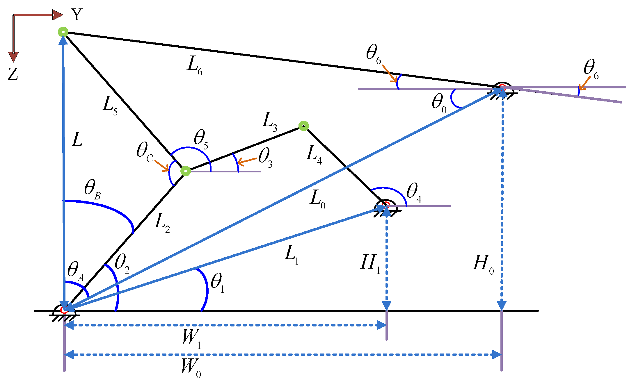
The roll structure of the seating plate was a toggle joint structure and is shown in Figure 3. , , , and represent the link lengths, where is the length of the driving link and is the seat length. In addition, , and represent the distances between the rotation axes and and are known. The constraint equations were required to satisfy the geometric relationship in the following Equations (11)–(14).
For the inverse kinematics of the roll axis, the angles of each link and the turning angle of the seating plate were obtained starting from . First, we determined and then solved in terms of and as:
could then be obtained from and . In addition, the following equation was satisfied:
According to (18), we obtained:
Based on , and , could be expressed as follows:
could then be calculated and given as:
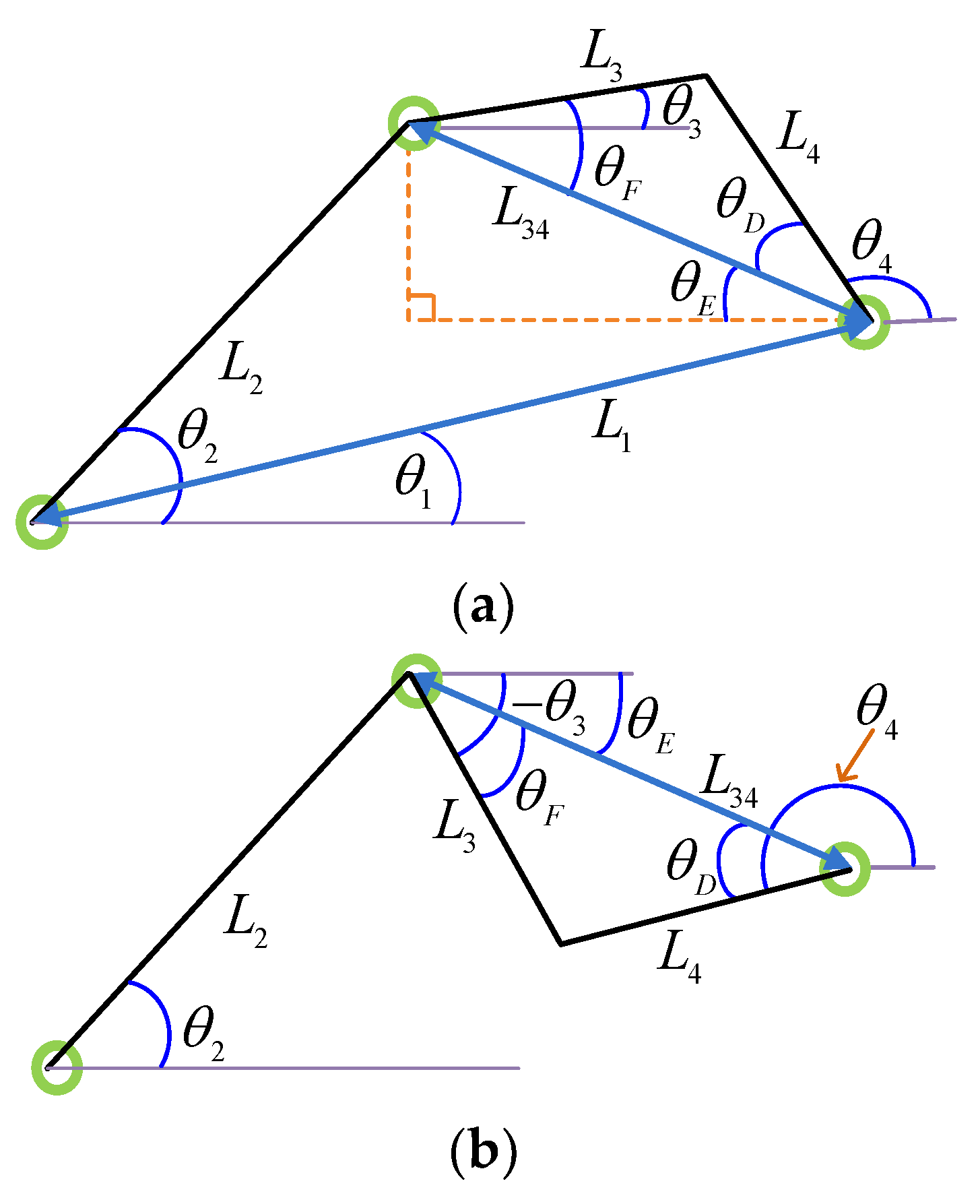
and were then solved. As shown in Figure 4a,b, there were two solutions for and .
Based on Figure 3 and Figure 4a, could be obtained from solution 1. was solved first and expressed as:
could be obtained from , and :
As shown in Figure 3, could be expressed as:
From Equations (25) and (26), could be obtained:
Similarly, could be obtained from , and ; could then be calculated as:
The next step was to solve . Given that , and had only one solution. could be obtained according to , and whereas could be obtained according to and :
From Equations (21), (27), (30), (31) and (33), the link angles could be obtained as control commands to realize the seating plate control in the roll region.
3.1.2. Heave Axis Design
In the heave axis, the seating plate structure was designed as a slider-crank mechanism, as shown in Figure 5, which was similar to the press machine in [19,20]. In Figure 5, represents the driving link, represents the initial height of the seating plate and z is the displacement of the seating plate. The displacement and the angles of each link were required to satisfy the constraints of Equations (34) and (35).
The inverse kinematics of the heave axis and the angles of each link from the z-axis displacement of the seating plate were first obtained. There were two solutions for this relationship, these are represented in Figure 6a,b.
and could then be obtained as:
By combining (40) and (41), we obtained:
Through this observation, the connecting rod angles in Equations (40) and (42) could be acquired as control commands and further realized the control of the seating plate of the heave region.
3.2. Kinematics of the Back Pad
3.2.1. Surge Axis Design
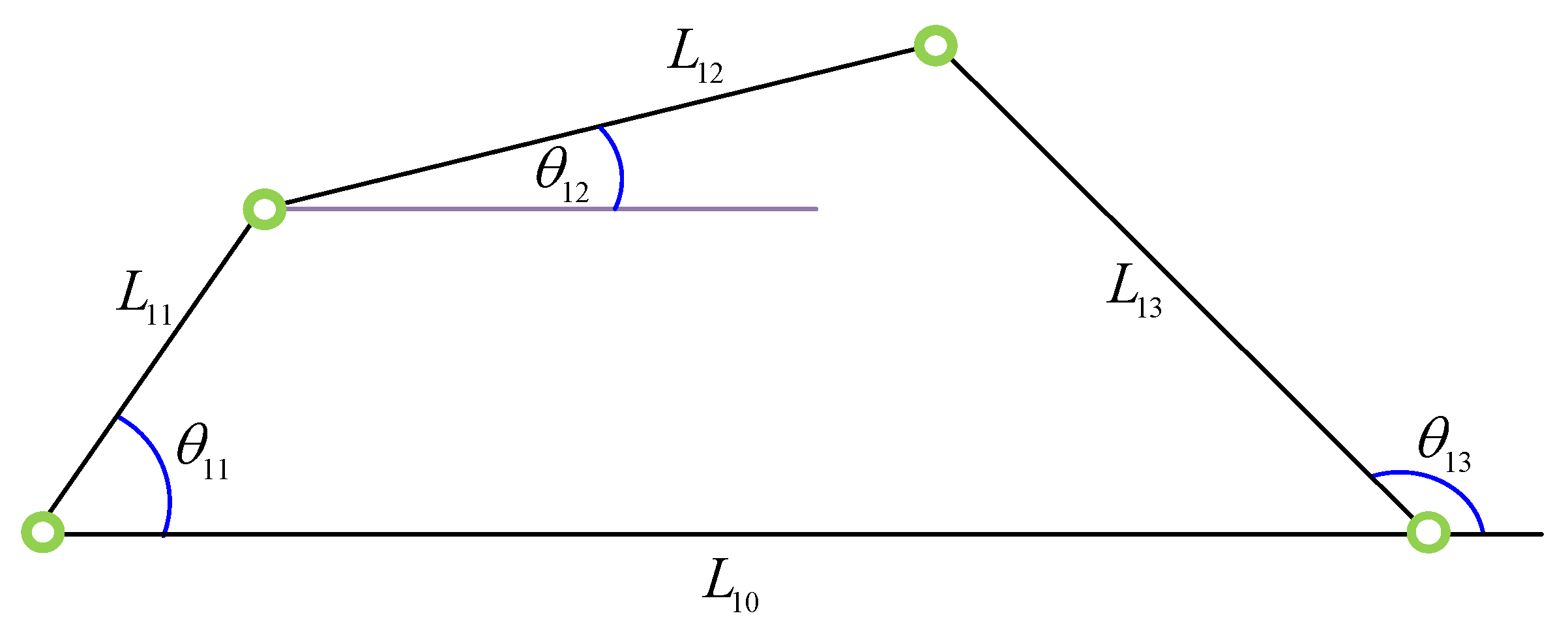
As shown in Figure 7, the surge axis structure of the back of the chair adopted a four-bar linkage mechanism. In Figure 7, represents the driving link and is the back of the chair. The angles of each link were required to satisfy Equations (43) and (44).
The inverse kinematics in the surge axis involved obtaining and from the turning angle and from the rear panel. As shown in Figure 8a,b, there were two solutions with the collinear boundaries of links and .
Based on Figure 8a, solution 1 was obtained from , , and where was first solved and represented as:
, ,
, and could then be obtained as follows:
The geometric relationship for Figure 8b was another solution. , and could be solved by the same method. and could then be found as follows:
From Equations (49)–(52), the angles of each link could be obtained as the control commands. In this way, the real-time panel control of the surge region was achieved.
3.2.2. Sway Axis Design
The sway axis structure design of the back pad was the same as that of the heave axis. Both were designed as the slider-crank mechanism shown in Figure 5. Hence, Equations (30) and (32) could be acquired according to the same derivation.
3.3. Kinematics of the Seat Height
The seat height design involved a ball screw that was employed as the adjustable height structure of the whole chair. Assuming that the lead of the ball screw was (m/rev), the relationship between the displacement and rotating angle was:
4. Implementation
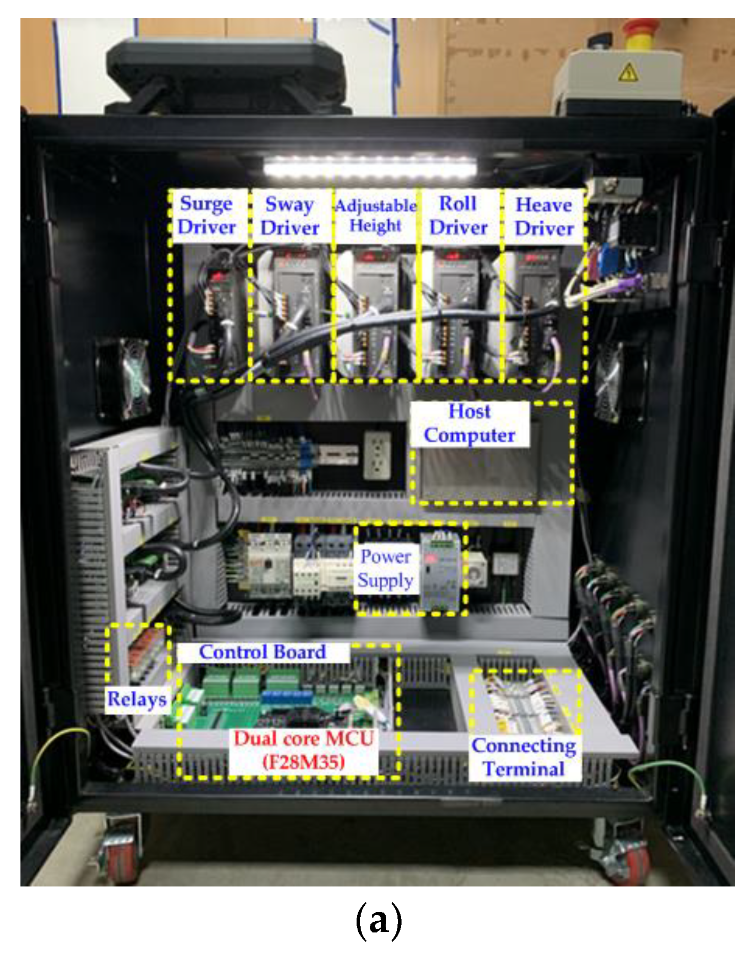
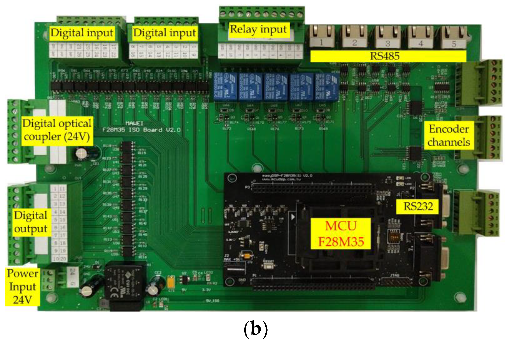
In this research, the main power was three-phase 220 volts used as the power supply source for the control box. The implemented circuit of the control box is shown in Figure 9a. The hardware circuit included a control board, a host computer, an AC to DC power supply, five sets of servo drivers, a set of relays, a connecting terminal and related components. The output of the AC to DC power supply was 24 V, which was used as the power supply of the control board. As shown in Figure 9b, the control board adopted a dual-core control processing chip (F28M35) produced by Texas Instruments for the implementation of the proposed control system. The F28M35 had an embedded Cortex-M3-based ARM processor as well as a C28 DSP core. The frequency of the ARM Cortex-M3 could reach 100 MHz, with 5 groups of UART and 74 individually programmable GPIOs. This research used five UART channels to perform the control mode release, command and servo status return to five sets of servo drivers. The frequency of the DSP 32-bit CPU was 150 MHz. It was integrated by digital input and digital output channels, including five servo motor signals, upper and lower limit signals and external button signals. The RS232 communication interface communicated with a host computer that was used to design the user interface.
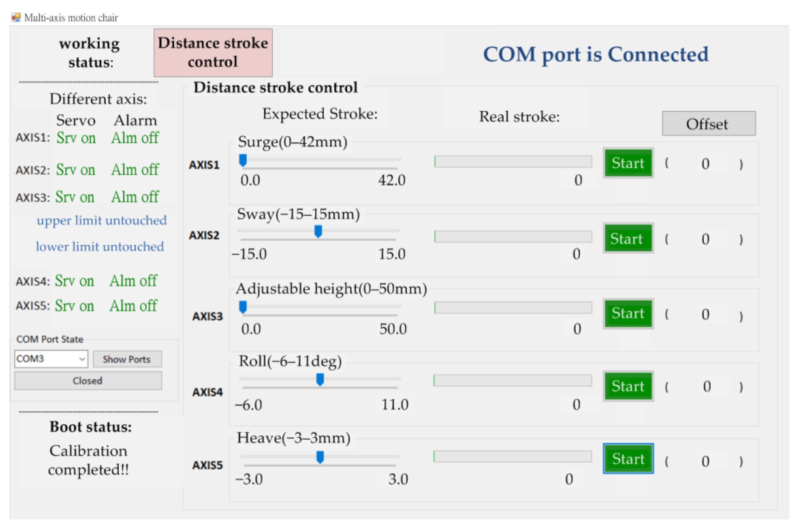
A user interface for the PC was established by C# software with a stroke control mode, as shown in Figure 10. The stroke mode adjusted the desired commands to be executed by sliding according to the selected number of servo axes. The commands were transmitted to the DSP through the digital communication interface to execute the kinematics and calculate the control commands sent to the drivers through the ARM to the selected number of servo axes. In this way, it realized multi-axis distance stroke control and achieved a closed-loop control. The block diagram of the control system is shown in Figure 11. It consisted of four parts. Part A was the control box, which provided a dual-core control processing chip and a host computer to communicate with five sets of servo motors through the serial communication RS485 interface. Part B was the back pan that could control the surge axis and the sway axis. Part C was the seat pan that could control the roll axis and the heave axis. Part D was the seat height that could adjust the height of the chair by servo motors. On the PC side, the RS232-to-USB device used a standard RS232 protocol with baud rates of up to 921,600 bit/s. The device could be controlled and configured over a serial interface by a set of control commands. According to the data processing on the PC side, a stable sampling rate above 100 Hz could be achieved in practice.
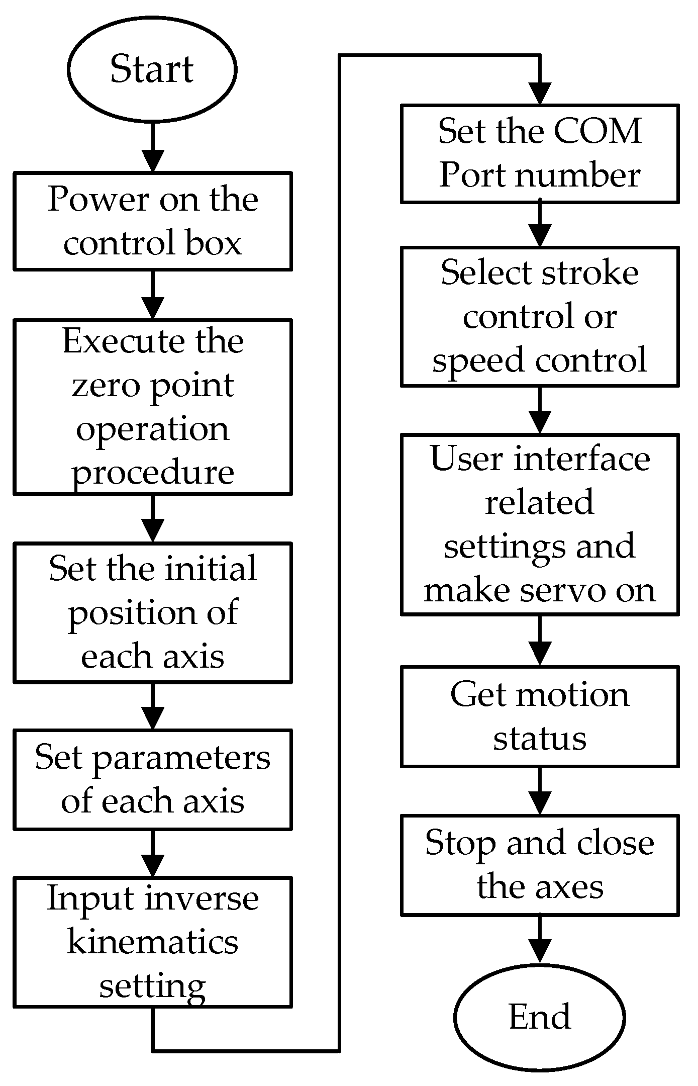
The control flowchart of the motion chair is shown in Figure 12. After starting the power supply, it performed an automatic zero-point procedure for each axis to obtain the correct initial position of the servo motors. After reading the parameters of the chair mechanism, executing the kinematics and selecting the COM port of the host computer to connect to, the user interface then generated the commands and monitored the operation status of each axis. The DSP used (TI F28M35; 150 MHz) worked with a control frequency of 100 Hz on the computational limit. The actual computation time required was 80 μs with an additional 10 μs for safety checks. The experimental motion chair is shown in Figure 13a. The dimensions of the chair are listed in Table 1. The chair was connected to the control box by five power lines, encoder lines and signal lines, as shown in Figure 13b. The layout in the control box is shown in Figure 9a. According to the proposed control scheme, user interface and software-embedded program, the dual-core control processing chip achieved the purpose of the system integration of the multi-axis servo motion chair. The servo motor parameters are listed in Table 2.
5. Experimental Results
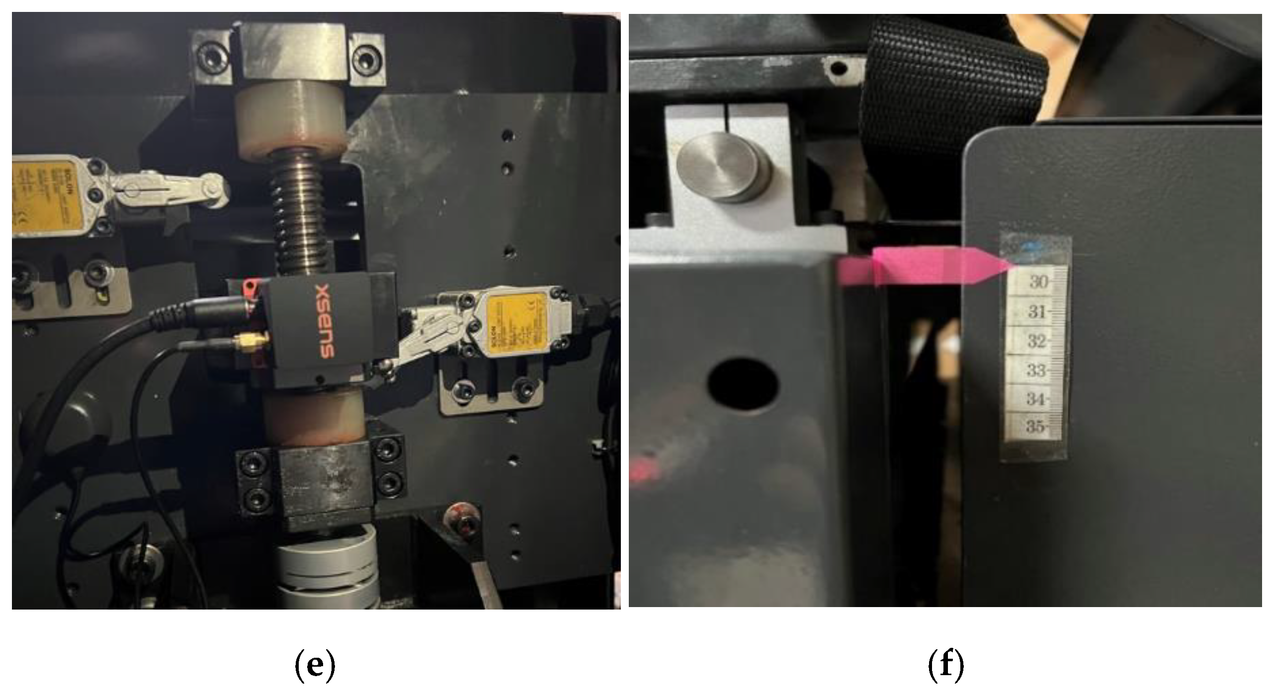
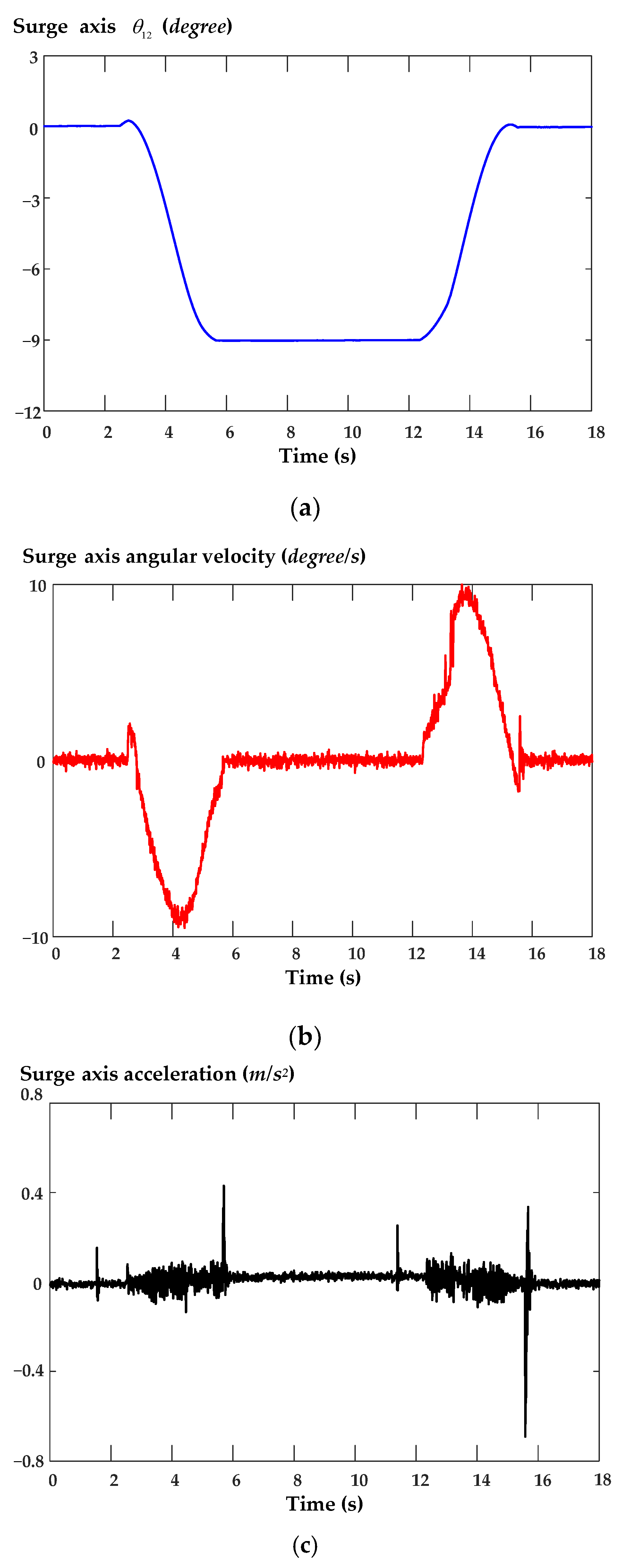
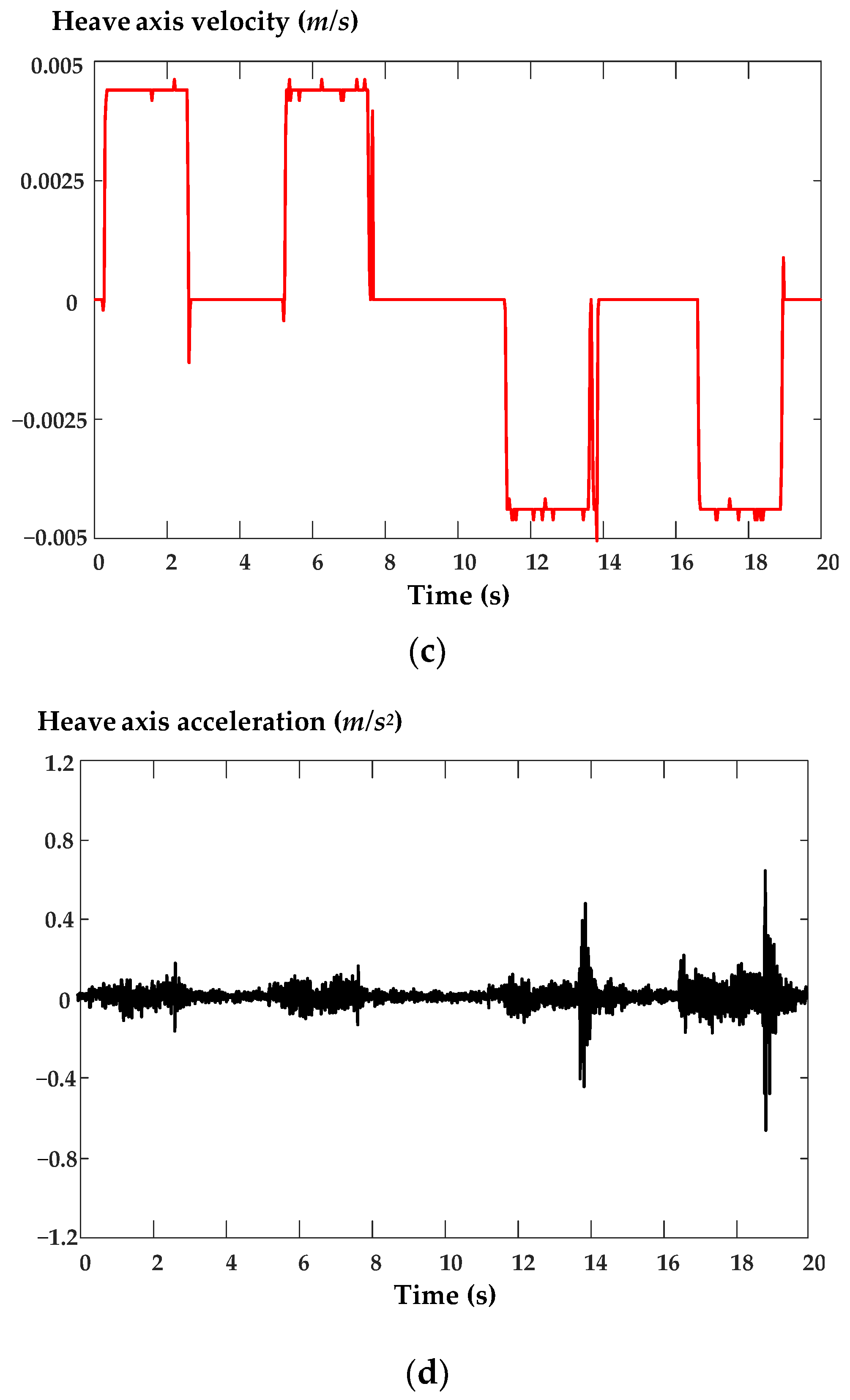
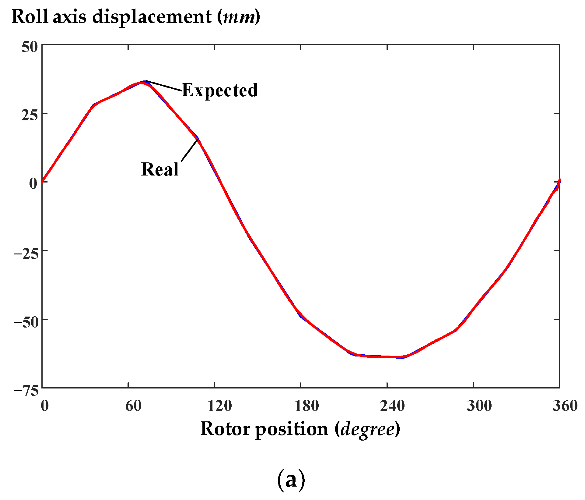
The measured steps for the components and the development of a four-axis chair motion system are described next. In terms of displacement measurements, we measured the total maximum displacement. The used tools were a vernier caliper, a metal ruler and a height gauge. The measurements for the four DOFs and the adjustable height conditions were as follows. The ball screw was FSIW-R25-5T4-172-265 with a lead of 5 mm. The total displacement of the adjustable height structure was 55 mm and the movable displacement was 50 mm. The total displacement of the surge axis was 42 mm. The total displacement of the sway axis was 30 mm. The total displacement of the heave axis was 6 mm. The total displacement of the roll axis was 100 mm. In addition, the used sensor was an MTi-680G inertial navigation system (INS), produced by Xsens Co; the INS uses an accelerometer and a gyroscope to measure the acceleration and angular velocity of objects. The transmission time was 10 ms. The output channel was an RS232 interface and the data were transmitted to the PC device through the RS232 to a USB. The characteristics of the sensor are shown in Table 3. The sampling rate of the sensor was selected as 100 Hz. The angles of the roll axis and pitch axis were in the range of ±90 degrees. The angle of the yaw axis was in the range of ±180 degrees; the angular velocity could reach ±2000 degree/s. The measurement reference point is shown in Figure 14a–f. Figure 15a shows that the measured displacement of the surge axis motor moved between 0 and 360 degrees, with a total displacement of about 42 mm. Figure 15b shows that the error between the two in Figure 15a was about 0.9 mm. Figure 16a–c show the tuning angle , relative angular velocity and acceleration responses measured using the INS. Figure 16a shows the surge axis from the zero point to the highest point. The corresponding tuning angle was about −9 degrees at this stroke. Figure 16b shows that the angular velocity of the surge axis was about ±10 degrees at this stroke. Figure 16c shows the x-axis acceleration of the surge axis, which ranged from −0.6 m/s2~0.4 m/s2. Figure 17a shows that the measured displacement of the sway axis motor was between 0 and 360 degrees and the total displacement in the observation figure was ±15 mm. Figure 17b shows that the error response was about 0.3 mm. Figure 17c shows the movement of the sway axis from the center point to the left and right limits. The speed of this stroke was about ±0.01 m/s with a maximum value around zero. In addition, Figure 17d exhibits the y-axis acceleration of the sway axis. Figure 18a shows that the measured displacement of the heave axis motor was between 0 and 360 degrees and the total displacement was about ±3 mm. Figure 18b shows that the error of the heave axis was about ±0.1 mm. Figure 18c shows that the heave axis moved from the center point to the upper and lower limits. The velocity was about ±0.004 m/s at this stroke. Figure 18d shows the z-axis acceleration of the heave axis. Figure 19a shows the measured displacement responses of between 0 and 360 degrees for the roll axis motor with displacements of about +35 mm and −65 mm; Figure 19b shows the error response. The roll structure of the seating plate was the toggle joint structure. As can be seen from the figure, the seat plate assembly tolerance error was about 0.7 mm. Figure 20a shows the response of the electrical angle of the roll axis motor. As the servo motors of the chair were 8-pole, the electrical angle of the roll axis for 4 revolutions corresponded with a mechanical angle of 360 degrees. Figure 20b shows that the stroke of the roll axis was from −6 to +11 degrees. Figure 20c shows that angular velocity of the roll axis was about ±70 degrees. Figure 21a shows that the displacement of the adjustable height motor was between 0 and 360 degrees with a total displacement of about 50 mm. Figure 21b shows that the error response was about 0.02 mm. Figure 21c shows the adjustable height from the lowest point to the highest point. The velocity was about ±0.014 m/s. It can be seen from the figure that the speed transient and steady state were relatively smooth; the reason was that the height adjustment of the seat was driven by the servo motor directly connected to the screw. Figure 21d shows the measured acceleration was close to 0.6 m/s2.
6. Conclusions
In this paper, the design, control and implementation of a digital control system for a four DOF adjustable-height chair were discussed. The architecture proposed consisted of a dual-core master controller and five slave drivers communicating together with RS485 and RS232 communication transmission interfaces. The first was used for the host computer and the digital control of the whole chair as well. The second one performed each axis drive of the motion chair mechanism such as the seat pan, back pad and seat height. The digital control systems of today have revolutionized the industrial world to virtually eliminate the typical drawbacks of analog systems and allow the diffusion of sophisticated control techniques that are not applicable without them. In order to achieve the predetermined motion path, the design and control of the chair structure as well as the mathematical model establishment, simulation and multi-axis servo drive technology were undertaken. The aim of the study was to develop a verification platform with a mathematical derivation, four DOFs, an adjustable height, software/hardware integration and relative control methods. An analysis of each component was conducted to gain an understanding of the structure assembly and further complete its production. The experimental results showed that the proposed multi-axis servo motion chair could bear a weight of about 90 kg.
Author Contributions
Conceptualization, M.-Y.W. and Y.-L.Y.; methodology, M.-Y.W. and Y.-L.Y.; software, J.-W.L.; validation, M.-Y.W., Y.-L.Y., J.-W.L. and H.-M.W.; resources, M.-Y.W. and Y.-L.Y.; writing—original draft preparation, M.-Y.W., J.-W.L. and H.-M.W.; writing—review and editing, M.-Y.W. and Y.-L.Y.; supervision, M.-Y.W.; funding acquisition, M.-Y.W. All authors have read and agreed to the published version of the manuscript.
Funding
This research received no external funding.
Institutional Review Board Statement
Not applicable.
Informed Consent Statement
Not applicable.
Data Availability Statement
This study did not report any data.
Conflicts of Interest
The authors has no conflict of interest to declare.
References
- Hammoumi, A.E.; Motahhir, S.; Ghzizal, A.E.; Chalh, A.; Derouich, A. A simple and low-cost active dual-axis solar tracker. Energy Sci. Eng. 2018, 6, 607–620. [Google Scholar] [CrossRef] [Green Version]
- Hammoumi, A.E.; Motahhir, S.; Ghzizal, A.E.; Chalh, A.; Derouich, A. Internet of Things-based solar tracker system. In Advanced Technologies for Solar Photovoltaics Energy Systems; Springer: Berlin/Heidelberg, Germany, 2021; pp. 75–95. [Google Scholar]
- Page, R.L. Brief history of flight simulation. SimTecT 2000 Proc. 2000, 1, 11–17. [Google Scholar]
- Available online: https://en.wikiversity.org/wiki/Flight_Simulator (accessed on 28 April 2022).
- Stewart, D. A platform with six degrees of freedom. Proc. Inst. Mech. Eng. 1965, 180, 371–386. [Google Scholar] [CrossRef]
- Gerathewohl, S.J. Fidelity of Simulation and Transfer of Training: A Review of the Problem; Federal Aviation Administration, Office of Aviation Medicine: Washington, DC, USA, 1969.
- Wei, M.Y. Design and implementation of inverse kinematics and motion monitoring system for 6DoF platform. Appl. Sci. 2021, 11, 9330. [Google Scholar] [CrossRef]
- Wei, M.Y. Design of a DSP-based motion-cueing algorithm using the kinematic solution for the 6-DoF motion platform. Aerospace 2022, 9, 203. [Google Scholar] [CrossRef]
- Lin, H.; Mcinroy, J.E. Adaptive sinusoidal disturbance cancellation for precise pointing of Sewart platforms. IEEE Trans. Control Sys. Technol. 2003, 11, 267–272. [Google Scholar]
- Gum, D.R. Modeling of the Human Force and Motion Sensing Mechanisms; Technical Report AFHRL-TR-72-54; Air Force Human Resources Laboratory: Dayton, OH, USA, 1973. [Google Scholar]
- Cardullo, F.M. Advanced G Seat for Aircraft Simulation. U.S. Patent 3,983,640, 5 October 1976. [Google Scholar]
- Berger1, D.R.; Pelkum, J.S.; Bulthoff, H.H. Simulating believable forward accelerations on a Stewart motion platform. ACM Trans. Appl. Percept. 2010, 7, 1–27. [Google Scholar] [CrossRef] [Green Version]
- Bruschetta, M.; Chen, Y.; Cunico, D.; Mion, E.; Beghi, A. A nonlinear MPC based motion cueing strategy for a high performance driving simulator with active seat. In Proceedings of the IEEE 15th International Workshop on Advanced Motion Control (AMC), Tokyo, Japan, 9–11 March 2018; pp. 23–28. [Google Scholar]
- Toda, Y.; Asano, K.; Yamamoto, K.; Yamamoto, F.; Hayakawa, S.; Tsutsumi, S.; Ikeura, R.; Yamakawa, T.; Yoshida, M.; Tsutsui, T.; et al. Verification of reducing effect of driver fatigue increase by using the driver’s seat with two support mechanisms. In Proceedings of the IEEE International Conference on Robotics and Biomimetics (ROBIO), Kuala Lumpur, Malaysia, 12–15 December 2018; pp. 1569–1573. [Google Scholar]
- Ishii, Y.; Ikeda, T.; Kobayashi, T.; Kato, Y.O.; Utsumi, A.; Nagasawa, I.; Iwaki, S. Investigation of the driver’s seat that displays future vehicle motion. In Proceedings of the IEEE 28th International Conference on Robot and Human Interactive Communication (RO-MAN), New Delhi, India, 14–18 October 2019; pp. 1–6. [Google Scholar]
- Halicioglu, R.; Dülger, L.C.; Bozdana, A.T. An automation system for data processing and motion generation. In Proceedings of the International Artificial Intelligence and Data Processing Symposium (IDAP), Malatya, Turkey, 16–17 September 2017; pp. 1–9. [Google Scholar]
- Berthoz, A.; Bles, W.; Bülthoff, H.H.; Grácio, B.C.; Feenstra, P.; Filliard, N.; Hühne, R.; Kemeny, A.; Mayrhofer, M.; Mulder, M.; et al. Motion scaling for high-performance driving simulators. IEEE Trans. Hum. Mach. Syst. 2013, 43, 265–276. [Google Scholar] [CrossRef]
- Fu, K.S.; Gonzalez, R.C.; Lee, C.S.G. Robotics Control, Sensing, Vision, and Intelligence; Mcgraw-Hill Book Co.: New York, NY, USA, 1987. [Google Scholar]
- Wang, F.; Qian, Z.; Yan, Z.; Yuan, C.; Zhang, W. A novel resilient robot: Kinematics analysis and experimentation. IEEE Access 2019, 8, 2885–2892. [Google Scholar] [CrossRef]
- Zhang, J.; Wei, H.; Shan, Y.; Li, P.; Zhao, Y.; Qi, L.; Yu, H. Modeling and experimental study of a novel multi-DoF parallel soft robot. IEEE Access 2020, 8, 62932–62942. [Google Scholar] [CrossRef]
- Mabie, H.H.; Reinholtz, C.F. Mechanisms and Dynamics of Machinery; Wiley: New York, NY, USA, 1987. [Google Scholar]
- Halicioglu, R.; Dülger, L.C.; Bozdana, A.T. Modeling, design, and implementation of a servo press for metal-forming application. Int. J. Adv. Manuf. Technol. 2017, 91, 2689–2700. [Google Scholar] [CrossRef]
- Cvok, I.; Hrgetić, M.; Hoić, M.; Deur, J.; Ivanovic, V. Design of a linear motor-based shaker rig for testing driver’s perceived ride comfort. Mechatronics 2021, 75, 102521. [Google Scholar] [CrossRef]
- Wei, M.Y.; Yeh, Y.L.; Chen, S.W.; Wu, H.M.; Liu, J.W. Design, Analysis, and Implementation of a Four-DoF Chair Motion Mechanism. IEEE Access 2021, 9, 124986–124999. [Google Scholar] [CrossRef]
- Bose, B.K. Technology trends in microprocessor control of electrical machines. IEEE Trans. Ind. Electron. 1988, 35, 160–177. [Google Scholar] [CrossRef]
- Xsens. MTi-680G RTK GNSS/INS. Available online: https://www.xsens.com/mti-680g (accessed on 10 June 2022).
Figure 1.
Schematic operation of the proposed multi-axis motion chair.

Figure 2.
The block diagram of the proposed servo drive system. The superscript “*” represent the reference command.
Figure 2.
The block diagram of the proposed servo drive system. The superscript “*” represent the reference command.

Figure 3.
Schematic of the seat plate rolling mechanism.

Figure 4.
and solutions: (a) solution 1; (b) solution 2.

Figure 5.
Schematic of the seating plate for the heave axis mechanism.

Figure 6.
and solutions: (a) solution 1; (b) solution 2.

Figure 7.
Schematic of a four-link mechanism.

Figure 8.
and solutions: (a) solution 1; (b) solution 2.

Figure 9.
Implemented circuit of motion chair drive system: (a) hardware circuit; (b) control board.
Figure 9.
Implemented circuit of motion chair drive system: (a) hardware circuit; (b) control board.


Figure 10.
The user interface.

Figure 11.
Configuration of a multi-axis motion chair control system.

Figure 12.
Control flowchart of the implementation.

Figure 13.
Details of the implemented system: (a) photo of the motion chair; (b) schematic of the wiring between the motion chair and electric control box.
Figure 13.
Details of the implemented system: (a) photo of the motion chair; (b) schematic of the wiring between the motion chair and electric control box.

Figure 14.
The measurement reference points: (a) surge axis; (b) sway axis; (c) heave axis; (d) roll axis; (e) adjustable height (front view); (f) adjustable height (side view).
Figure 14.
The measurement reference points: (a) surge axis; (b) sway axis; (c) heave axis; (d) roll axis; (e) adjustable height (front view); (f) adjustable height (side view).


Figure 15.
Measured responses of the surge axis: (a) displacement; (b) error.

Figure 16.
Measured responses of the surge axis: (a) tuning angle; (b) angular velocity; (c) acceleration.
Figure 16.
Measured responses of the surge axis: (a) tuning angle; (b) angular velocity; (c) acceleration.

Figure 17.
Measured responses of the sway axis: (a) displacement; (b) error; (c) velocity; (d) acceleration.
Figure 17.
Measured responses of the sway axis: (a) displacement; (b) error; (c) velocity; (d) acceleration.


Figure 18.
Measured responses of the heave axis: (a) displacement; (b) error; (c) velocity; (d) acceleration.
Figure 18.
Measured responses of the heave axis: (a) displacement; (b) error; (c) velocity; (d) acceleration.


Figure 19.
Measured responses of the roll axis: (a) displacement; (b) error.


Figure 20.
Measured responses of the roll axis: (a) electrical angle; (b) stroke; (c) angular velocity.
Figure 20.
Measured responses of the roll axis: (a) electrical angle; (b) stroke; (c) angular velocity.


Figure 21.
Measured responses of the adjustable height: (a) displacement; (b) error; (c) velocity; (d) acceleration.
Figure 21.
Measured responses of the adjustable height: (a) displacement; (b) error; (c) velocity; (d) acceleration.


Table 1.
Dimensions of the chair.
| 10 mm | |
| 180 mm | |
| 3 mm | |
| 10 mm | |
| 22.5 mm | |
| , | 15 mm, 3 mm |
| , | 75 mm, 70 mm |
| 388.5 mm | |
| 52.5 mm | |
| 192.2 mm | |
| 224 mm | |
| 16 mm | |
| 4.5 mm | |
| 22.5 mm | |
| 122.5 mm |
Table 2.
Parameters of the motor.
| DOF | Surge | Sway | Roll/Heave | Adjustable Height | |
|---|---|---|---|---|---|
| Item | |||||
| Power dissipation | 0.75 kW | 1.3 kW | 3.0 kW | 2.0 kW | |
| Rated voltage | 220 V | 220 V | 220 V | 220 V | |
| Rated current | 4.3 A | 11.4 A | 14 A | 9 A | |
| Rotor inertia | 1.03 kg-cm2 | 20.77 kg-cm2 | 18.62 kg-cm2 | 12.84 kg-cm2 | |
| Rated speed | 3000 r/min | 1500 r/min | 2000 r/min | 2000 r/min | |
| Maximum speed | 5000 r/min | 3000 r/min | 2500 r/min | 2500 r/min | |
| Rated torque | 2.39 N.m | 8.34 N.m | 14.327 N.m | 9.55 N.m | |
| Maximum torque | 7.16 N.m | 23.3 N.m | 42.96 N.m | 28.65 N.m | |
Table 3.
Specifications of gyroscope and accelerometer of Xsens MTi enclosure [26].
Table 3.
Specifications of gyroscope and accelerometer of Xsens MTi enclosure [26].
| Gyroscope | Acceleration | |
|---|---|---|
| Range | ±2000 degree/s | ±10 g |
| In-run bias stability | 4 degree/h | 15 μg |
| Bandwidth (−3 dB) | 500 Hz | 500 Hz |
| Operating Temperature | −40 to 85 °C | |
| Input voltage | 4.5 to 24 V | |
| Power consumption | <1 W | |
Publisher’s Note: MDPI stays neutral with regard to jurisdictional claims in published maps and institutional affiliations. |
© 2022 by the authors. Licensee MDPI, Basel, Switzerland. This article is an open access article distributed under the terms and conditions of the Creative Commons Attribution (CC BY) license (https://creativecommons.org/licenses/by/4.0/).
Share and Cite
MDPI and ACS Style
Wei, M.-Y.; Yeh, Y.-L.; Liu, J.-W.; Wu, H.-M. Design and Control of a Multi-Axis Servo Motion Chair System Based on a Microcontroller. Energies 2022, 15, 4401. https://doi.org/10.3390/en15124401
AMA Style
Wei M-Y, Yeh Y-L, Liu J-W, Wu H-M. Design and Control of a Multi-Axis Servo Motion Chair System Based on a Microcontroller. Energies. 2022; 15(12):4401. https://doi.org/10.3390/en15124401
Chicago/Turabian StyleWei, Ming-Yen, Yen-Liang Yeh, Ji-Wei Liu, and Hsiu-Ming Wu. 2022. "Design and Control of a Multi-Axis Servo Motion Chair System Based on a Microcontroller" Energies 15, no. 12: 4401. https://doi.org/10.3390/en15124401
Note that from the first issue of 2016, this journal uses article numbers instead of page numbers. See further details here.