
The Architecture Optimization and Energy Management Technology of Aircraft Power Systems: A Review and Future Trends
by
 , ,
, ,
Tao Lei
1,2,* ,
,
Zhihao Min
2,
Qinxiang Gao
1,2,
Lina Song
1,2,
Xingyu Zhang
2 and
Xiaobin Zhang
1,2 1
Department of Electrical Engineering, School of Automation, Northwestern Polytechnical University, Xi’an 710129, China
2
Key Laboratory of Aircraft Electric Propulsion Technology, Ministry of Industry and Information Technology of China, Xi’an 710072, China
*
Author to whom correspondence should be addressed.
Energies 2022, 15(11), 4109; https://doi.org/10.3390/en15114109
Submission received: 17 April 2022
/
Revised: 22 May 2022
/
Accepted: 24 May 2022
/
Published: 2 June 2022
(This article belongs to the Special Issue Power System Dynamics and Renewable Energy Integration)
Abstract
:With the development of More/All-Electric Aircraft, especially the progress of hybrid electrical propulsion or electrical propulsion aircraft, the problem of optimizing the energy system design and operation of the aircraft must be solved regarding the increasing electrical power demand-limited thermal sink capability. The paper overviews the state of the art in architecture optimization and an energy management system for the aircraft power system. The basic design method for power system architecture optimization in aircraft is reviewed from the multi-energy form in this paper. Renewable energy, such as the photo-voltaic battery and the fuel cell, is integrated into the electrical power system onboard which can also make the problem of optimal energy distribution in the aircraft complex because of the uncertainty and power response speed. The basic idea and research progress for the optimization, evaluation technology, and dynamic management control methods of the aircraft power system are analyzed and presented in this paper. The trend in optimization methods of engineering design for the energy system architecture in aircraft was summarized and derived from the multiple objective optimizations within the constraint conditions, such as weight, reliability, safety, efficiency, and characteristics of renewable energy. The cost function, based on the energy efficiency and power quality, was commented on and discussed according to different power flow relationships in the aircraft. The dynamic control strategies of different microgrid architectures in aircraft are compared with other methods in the review paper. Some integrated energy management optimization strategies or methods for electrical propulsion aircraft and more electric aircraft were reviewed. The mathematical consideration and expression of the energy optimization technologies of aircraft were analyzed and compared with some features and solution methods. The thermal and electric energy coupling relationship research field is discussed with the power quality and stability of the aircraft power system with some reference papers. Finally, the future energy interaction optimization problem between the airport microgrid and electric propulsion aircraft power system was also discussed and predicted in this review paper. Based on the state of the art technology development for EMS and architecture optimization, this paper intends to present the industry’s common sense and future trends on aircraft power system electrification and proposes an EMS+TMS+PHM to follow in the electrified aircraft propulsion system architecture selection
1. Introduction
Traditionally, the energy or power system in aircraft can be classified as the primary power system and secondary power system. The primary power is thrust mainly provided by the petroleum oil engines, the secondary power can be divided into hydraulic, pneumatic, and electrical power, which can extract mechanical energy from the engine for control and maneuverability. There is a growing trend toward electrification of the aircraft power system for various aircraft segments. The major motivation for this includes increased efficiency, reduced CO2 emissions, and lower operating costs [1]. In the electrified aircraft concept, the duct or propeller fan is driven by an electric motor, whereas, in a conventional aircraft, a gas turbine engine drives the duct fan. Secondary power systems allow for aircraft safe operation and ensure passengers’ comfort. For conventional aircraft, secondary power systems combined pneumatic, hydraulic, mechanical, and electric power, and their energy consumption represents approximately 5% of the total fuel burned during the flight stage [2].
With the advent of the More Electric Aircraft (MEA) and All-Electric Aircraft (AEA) initiatives, electric power systems are progressively taking the place of pneumatic, hydraulic, and mechanical power systems [3]. Electric power is the only energy form on board. In recent years, with the development of green and clean aviation, electric aircraft is a path to zero-emission air travel [4]. In particular, the aims of this research are focused on the onboard power systems of new All-Electric Aircraft and electrical propulsion aircraft, where a crucial design point is related to the electrical energy optimization management and power control [5,6,7].
In the “all-electric” concept, where pneumatic and hydraulic power systems are eliminated to improve aviation costs and environmental impact, the dynamics of electrical power balance are to be characterized and managed to avoid excessive peaks with respect to generators’ limited capabilities. Especially for electric propulsion aircraft (EPA), the thrust force can be partly or completely provided by an electric power system [8]. With the development of power electronics, the HVDC system is becoming a trend for MEA/AEA and EPA [9]. The energy storage system such as the Lithium-ion battery is often integrated into the electrical power system to improve the performance of the power system. The aircraft’s electrical power system is a “flying microgrid” to realize the different flight functions.
Renewable energy, such as the fuel cell and the photovoltaic battery, has been integrated into the aircraft electrical power system as the auxiliary power unit [10], emergency power [11], or main propulsion hybrid energy source [12]; the output power characteristics of renewable energy further degraded the power quality of the electrical power system on board. The necessity of energy and power management is obvious to the engineering designer. In recent years, the aircraft electric propulsion has become an important research topic, this trend gives a higher requirement for the energy system, especially for the electric power system in the aircraft. Due to their performance variation with power and energy requirements and the size of the components, a mix of chemical, electrical and mechanical components can be integrated in aircraft electric propulsion systems [13,14]. To evaluate the mass and performance index of these systems, one method is to use a constant specific power density, or power-to-mass ratio, and efficiency for each device in the aircraft power system for economic issues [15]. The stability and power quality of aircraft power systems must be considered with the optimization of energy management, while the thermal energies are generated and transmitted onboard due to power loss from the typical energy component.
The optimization of energy onboard the aircraft can be classified into two main fields: (1) Static architecture and configuration optimization, evaluation for power system; (2) Dynamic energy and power planning or management methods to fulfill the real-time requirement of efficiency, stability, reliability, and safety for the power system. It is not similar to the terrestrial energy system which is mainly focused on the efficiency and cost, and reliability of system operation without considering the weight, volume and power loss, and security of the energy system [16,17]. The power system in aircraft must have very high reliability and safety; there is a lot of research regarding the fault tolerance, safety, and reliability of power systems in aircraft [18,19,20,21,22,23]. Compared with vehicle and ship power systems, the safety requirement for aircraft is more stringent. So the energy optimization for aircraft must include health management and fault analysis, considering the different voltage levels, load characteristics, and architecture, compared with ground vehicles and ships [24].
For the static optimization and assessment of the energy and power system of aircraft, there are component levels [25,26], subsystem levels [27,28,29,30,31], and system levels [32,33,34,35] in the design optimization and evaluation. The number of main designing parameters of typical energy conversion devices, such as the generator and motor, and power converter, is very high and the coupling relationship of different energy is very complex [36]. So the methods of evaluation and optimization in the energy system in the MEA/AEA or EPA must be built based on the mathematical multi-parameter programming [37] and power flow analysis [38]. In some situations, the designing variable and optimization variable parameters include the integer number, for example, some of the optimization Boolean variables are 0 or 1, such as the switching operating status decision, and the integer number of the battery’s cell or generator in a power system [39,40]. Therefore, these optimization problems can also be changed into multi-parametric mixed-integer linear programming (MILP). To formulate and solve an optimization problem in energy systems, there are numerous elements that need to be defined, including the system’s parameter boundaries, optimization criteria, decision variables, and objective functions according to different energy architectures of aircraft. Assessment tools are developed for the overall MEA power system [41].
In addition, for dynamic energy and the power management system onboard, traditional MEA power demands are not changed greatly because of the small percentage of electrical power out of the overall power from the engine [2], so the energy management framework and control methods are simple. However, for all-electric and electrical propulsion aircraft, the energy demand from the EPA is greatly variable during the flight stage; according to the aerodynamic control requirements, the power balance must be maintained in every time instant [42], so the real-time dynamic energy and power management strategies must be considered. Although the dynamic energy management methods are very conservative in traditional aircraft power systems, the regenerated energy is not allowed to feed into the aircraft electric power system. Furthermore, the fixed priority of the electrical load and the active energy management strategies are still beneficial to the aircraft, while considering the demand of EPA [43,44,45]. Many energy and power management system architectures are proposed from the power source, power distribution network, and power load side to coordinate these components [46,47,48,49,50,51,52,53]. The energy and power management control methods are elaborated upon to realize the optimization objective such as fuel consumption minimization, flight cost minimization, system reliability maximum, quick power response, stability enhancement, and power quality improvement. The energy and power optimization is applied to flight control subsystem [47], environmental control system [46], electrical power generation and distribution system [49,50,51,53], and load management system [48,52].
This article aims to present a comprehensive review of electrified aircraft electric power and propulsion systems. The key technology progress and trends such as architecture optimization and energy management control were discussed here. The major topic items can be listed as follows:
- (1)
- Architecture evaluation and optimization of the aircraft power systems;
- (2)
- Energy power source analysis for power systems with different sizes of aircraft;
- (3)
- Power load characteristic and requirements analysis for aircraft power system;
- (4)
- Energy management strategies and control architecture for aircraft power systems;
- (5)
- Electrical thermal coupling and integrated control methods for aircraft power system;
- (6)
- The energy or power interaction analysis and control between the electric aircraft power system and airport microgrid can improve the performance of both systems;
In this paper, the architecture research and design methods of the aircraft system are reviewed in Section 2 The characteristics of energy power for aircraft, especially with renewable energy integrated, has been analyzed, and the challenging problem for energy source and power management strategies of the electric power system was presented, regarding the uncertainty from the power source and load power demand, in Section 3 and Section 4. The optimization problem of energy efficiency and power distribution systems in aircraft was discussed in Section 5. Research progress of different energy and power management architecture and strategies are also presented in Section 5. Section 6 gives a review of thermal and electrical coupling issues in aircraft power systems. The developing trend for the connection of the airport microgrid and EPA is provided in Section 7, the energy management control research issues can be derived from their interaction. Finally, the conclusion of the state art EMS was presented, to predict the arriving era of EPA, in Section 8.
2. The Review of Power Architecture Research of Aircraft Power Systems
In this section, the definition of the power system consists of a system in which a group of components works together as a system and delivers electric power and thrust power to the aircraft. The aircraft power system is sometimes split in to two different categories: the electric propulsion system responsible for providing the electric thrust power and the electric power system response for supplying electric power for avionic equipment or an electric actuator.
2.1. The Selection of the Architecture of Aircraft Power Systems
The typical power system architecture of aircraft is shown in Figure 1a. The power flow of multiple energy domains at the system level, for a generic aircraft power architecture, illustrates the decomposition that will be utilized to cope with the complexity of this multi-physics domain model. Traditionally, the power subsystem design is independently carried out by different single energy forms, leading to overly conservative system sizing results [54]. Except for generating the thrust force for aircraft, the engine model also provides mechanical, hydraulic, and pneumatic power from shaft power, while also acting as a sink for waste heat via bypass duct heat exchangers. The electrical system converts mechanical power to electrical power with power loss or waste heat as a byproduct. The thermal management system uses electrical and pneumatic power to move and reject thermal energy around the aircraft. With the development of renewable energy, the PV and fuel cell, or hydrogen energy, can be used for the aircraft electrical power system [12,13]. Compared with engine-driven generators, the energy efficiency of green power energy is a big advantage. However, their energy density is limited, so these kinds of energy are often used with the oil-engine-driven generator. For future aircraft power systems, renewable energy such as photovoltaic (PV) systems and fuel cells can be integrated into the power system of aircraft, while the energy extraction from the engine can be reduced to improve the overall efficiency of aircraft power systems. The architecture of more electrical aircraft power systems is shown in Figure 1b. In this architecture, the bleed air system can be eliminated, and the ECS and ice protection system can get the electrical energy from the electrical power systems [2]. All-electric and electrical propulsion aircraft are presented in Figure 1c. This is the turbo electrical power system architecture for medium- and large-size aircraft [42]. A typical power system architecture of unmanned air vehicles (UAV), and small size or light aircraft integrated with renewable energy power sources, is given in Figure 1d [55,56]. In some situations, the different configurations of the renewable power source, such as PV or fuel cell, can be realized depending on the size of the aircraft and the power demand from the load [57].
As power systems become more integrated, traditional design silos are being broken down in favor of cooperative design between thermal, electrical, and mechanical engineers [8]. The optimization design of aircraft power system structure is basically a complex optimization problem, which is to find the optimal solution in a huge parameter space. The selection of architecture for power systems must be regarded with volum e, weight, reliability, and efficiency. According to the above constraints, the evaluation and optimization methods can be applied to be an iterative process to find the optimal structure of the aircraft power system.
2.2. The Optimization and Evaluation of Architecture for Aircraft Power Systems
In the aircraft power system architecture design, the modeling of typical components is very important, where power equipment/subsystems coming from different physical energy domains (thermodynamic, aerodynamic, hydraulic, electrical, etc.) work and interact with each other [58]. It is clearly concerned with finding the initial equilibrium condition and defining solver settings, such as the numerical method and the chosen time step [59], while regarding the integration of complex power models describing various physical phenomena with respect to quite different frequency contents.
The basis of the analysis tool for different architectures of AEPS is a library of component models covering the main power subsystems; these component models can be integrated to form user-defined power system architectures, which can be quantitatively assessed about some performance index, such as both mass and energy or exergy efficiency, throughout various operating modes, or flight cycles, of the aircraft power system [58]. According to the second law of the thermodynamic system, the energy is the available energy of the working medium, and it is used to determine the portion of given energy that is likely to be useful in a given state of a thermodynamic system.
The traditional small-signal modeling methods are often used for power system stability analysis and control loop design [16]. However, these methods are not fit for the multi-source microgrid application; some methods are given in some papers to overcome this obstacle to meet the demands from the AEA and EPA [59]. Although the multi-generator VF electric power system, based on the dynamic phasor model, is provided [60], this is very difficult to integrate with thermal energy flow analysis.
In [54,58], posing the problem of safe, robust, and efficient design and control, it needs a new method or idea for a basic multi-layered modeling framework that may lend itself to ripping potential benefits from the electrification of terrestrial power systems, ships, or aircraft. The modeling methods, based on exergy analysis with the second law of thermodynamics, were presented for the power system. For the multi-physical systems, such as terrestrial energy systems, aircraft, and ship power systems, the interconnected systems are modeled as dynamically interacting power modules with different time scales. This approach is shown to be particularly well-suited for the scalable optimization of large-scale complex power systems. The proposed multi-layered modeling of system dynamics in the energy and exergy space offers a promising basic method for modeling and controlling inter-dependencies across multi-physics subsystems, for ensuring both feasible and near-optimal operation.
From an operational research point of view, architecture optimization of the power system is the process of maximizing or minimizing a linear or nonlinear analytical objective function, regarding various equality or inequality constraints, for a number of design variables or parameters; for each of these, a range of value exists. Set more simply and practically, optimization design problem involves finding the best possible configuration and variables solution for a given problem with reasonable constraints.
Optimal conditions are generally strongly dependent on the chosen objective function, which can involve the figure of merits (FOM) for the aircraft power system. However, several aspects of the performance index are often important in practical applications for the aircraft power system. In aircraft thermal and energy systems design, efficiency (energy and/or exergy), power production rate, reliability, power quality, and heat transfer rate are common quantities or FOM that are to be maximized, while cost, weight, fuel consumption, environmental impact, and power loss are quantities to be minimized. Any of these can be chosen as the objective function for an optimization problem, but it is usually more meaningful and useful to consider more than one objective function. In a common situation, several optimization objects maybe contradictory to each other, while one objective function is optimal and the other is not optimal under the same operating points. The minimum and maximum of a single variable function are able to be determined by users of simple linear optimization, and first or second derivative techniques to find the optimal value of a given function can be utilized. At the advanced level, an optimum value of multivariable nonlinear functions can be found by users of optimization. In addition, multivariable optimization problems with nonlinear constraints can be solved. A constrained optimization problem is an important research subject in scientific practice since most real-world problems contain constraints [61].
Multi-objective optimization has been extensively used and studied for aerospace power systems [12,14,21,28,33]. There exist many algorithms and application case studies involving the multi-objective optimization of aircraft power systems [30,35,37].
One of the common approaches for dealing with multiple objective functions is to combine them with some weighting factor into a single objective function that is then minimized or maximized. For example, in the optimal design of heat exchangers and cooling systems for electronic equipment in aircraft power systems, it is desirable to minimize the exergy destruction rate and maximize the heat transfer rate [62]. However, this often comes at the price of increased fluid flow rates and corresponding frictional pressure losses for cooling systems. A multi-objective optimization problem has objective functions that are either minimized or maximized [54]. As with single-objective optimization, multi-objective optimization involves several linear or nonlinear constraints that any feasible solution, including the optimal solution, must satisfy. In addition, electric, hydraulic, and pneumatic energy are integrated into aircraft power systems [63]. The heterogeneous energy optimization problem often makes the objective function very complex and parameter normalization is not very easy to tackle. The electrification trend of the aircraft power system can mitigate the complexity.
The power management optimization problem is formulated as Equation (1).
Minimize/maximize
Subject to
In the above equation, is the objective function, the inequality constraints, and the equality constraints. A solution to this problem is , which is a vector of n decision variables or design parameters. The last set of constraints in Equation (4) is called the variable bounds, which restrict the boundary of searching space. Any solution of the decision variables should be within limits with a lower bound and upper bound . To illustrate this problem, consider this situation: the multi-objective optimization model has two objective functions, and [61]. It is assumed that these two functions are to be minimized (although maximization can be similarly handled since it is equivalent to the minimization of the negative of the function). The values for the two objective functions at five different design points are shown in Figure 2A. Design point 2 in this figure is clearly found to be preferable to design 4 because both objective functions and are smaller for design 2 compared to design 4. Similarly, objective functions in design 3 are optimal for design 5. In addition, designs 1, 2, and 3 are not predominated, by any other parameter design variation.
The aggregation of non-dominated designs is formed as the Pareto frontier curve, representing the best collection of design parameter points of the aircraft power system. Figure 2B shows this curve. Note that an optimal design condition can be selected from any point on the Pareto frontier. The choice of a specific design from the set of points forming the Pareto frontier curve is at the experience and judgment of the optimal decision maker. The aircraft power system maybe has many optimization objectives from the energy or power field such as weight, reliability, efficiency, volume and cost for fuel consumption, which can be expressed in Equation (1). The power flow balance relationship is shown in Equation (3). Some variation rates of power output for the generator or battery can be formatted in inequality constraints (2). The decision variable or design variable in the optimization model is sometimes stochastic, such as the load power demand or some power source like PV, so the stochastic optimization and robust optimization methods must be provided.
For the aircraft electrical power system, the energy efficiency function of power generators can be written in the following equation [41]:
where are the coefficients for the efficiency of the power generator from the polynomial fitting according to the data from the experiments and simulations. The different typical efficiency curves of power converter components in aircraft power systems are shown in Figure 3a–d. By using this method, the model of the auto-transformer rectifier unit (ATRU), dual active bridge (DAB) converter, some DC–DC converters, and a voltage source inverter (VSI) can be built to achieve the power system level efficiency optimization [53]. From Equation (5), the efficiency of the power converter is nearly the convex function, and this will reduce the difficulty of the optimization problem.
Optimization problem reformulation of the architecture of the aircraft power system can be expressed by the following, with regard to the system’s power efficiency:
Problem: PMS with multiple objective optimization for the aircraft power system
Minimize
where the is the efficiency function of power generators, , the g is the set of power generators in EPS; , the is the set of power converters in EPS. is the efficiency function of power converters for an aircraft power system.
In an aircraft power system, the energy static optimization problem formation must be regarded with many constraints such as volume, weight, heat dissipation, and reliability. The optimal architecture and configuration for aircraft power systems can be derived based on optimal parameters and optimal distribution from the different power source. The power optimal scheduling problems to achieve a good balance on multiple objectives include ensuring optimal operating ranges for generators, obtaining a higher efficiency area of generators and power converters by utilizing the electric storage system according to variation in the power demand, and also maintaining the power priority in the connections of generators, power buses, and electric loads at the optimal performance index. There are several equipment examples in AEPS to explain these constraints [64].
- Power Bus and Load Priority Constraints: Two kinds of priority constraints in the traditional AEPS can be regarded: the electric load priority constrants in the matter of critical and noncritical electric loads, and bus priority constraints in the matter of preset priority lists or the connections between each generator and primary power buses, and between each primary bus and secondary distributed power buses. The priority constraints are realized by adding a sequence of penalty factors in an objective function for different power buses and loads—the higher the priority, the larger the penalty factors [64].
- Generator and Bus Power Capacity Constraints: The power generated by each generator must be held within its limits of power rating change and capacity, while the power transferred through each bus should not exceed the upper bound. In some situations, this constraint is formed as the combined optimization problem [65].
- Power Balance Constraints With Consideration of Power Efficiency: The required power to the main power buses may only be supplied by one main generator. Similar to the secondary bus power allocation, a redundant or emergency bus should be considered in case of a failure of the first allocated generator. In addition, the power balance equation is normally a quadratic function; this can reduce the convexity of the objective function [66].
- Bus Connection Constraints: At each time instant, the main bus should only be connected to one generator. According to the optimization model of the aircraft power system, the objective function, decision variables, and constraints have been presented based on the above consideration. The distributed solid-state power distribution system can control the load by connecting or disconnecting the secondary bus by a discrete switching signal. The optimization objective function is a nonlinear function and is non-differential in parameter space [67].
In general, classical optimization techniques are useful to search for the optimum solution or unconstrained maximum or minimum of continuous and differential functions. It is very easy to find the optimal value. Some specifications for numerical optimization can be selected based on this understanding, as described below briefly:
- Linear programming (LP). The optimization objective function is a linear function for decision variation, while the constraints for variables are linear. Basically, this optimization model is a convex optimization. The simplex methods and interior points methods can solve this problem. For AEPS’s simple architecture or small-size dc power system, the optimization of energy efficiency can be realized as the LP problem [12,45].
- Quadratic Programming (QP): Allows the objective function to have quadratic terms, while set A must be specified with linear equalities and inequalities. Although some optimization models are not convex optimization, the relaxation and approximation of non-convex optimization can achieve the optimal solution accurately. For the AC power system of large-sized aircraft, the power scheduling optimization can be regarded as the QP problem [30,64].
- Nonlinear programming: Applies to the general case in which the objective function, or the constraints, or both, contain nonlinear parts. Regarding aircraft multi-energy power systems including electric power systems, hydraulic systems, and thermal management systems, the energy optimization problem is a nonlinear programming problem [27,37].
- Combinatorial optimization: Concerns problems where the set of feasible solutions is discrete or can be reduced to a discrete one. For example, some power loads with a different priority can be connected to a secondary power bus with limited power capacity, the optimal configuration of the electric load must be found with the different flight stages. In this situation, the aircraft power system optimization problem is a mixed integer linear programming problem (MILP) [31,48], which can be solved by some mature solver such as Gurobi, CPLEX, GAMS, and the special power system planning software.
- Evolutionary algorithm: Involves numerical methods based on a random search. Other heuristic-based methods such as particle swarm optimization (PSO), fuzzy logic-optimization, simulated annealing methods (SA), and the genetic algorithm (GA) can be used to find the optimal value space in aircraft power system architecture design [68]. While the optimization function of aircraft power systems is nonlinear and non-convex, heuristic methods can be applied to solve this problem. The solution to this optimization maybe not a global optimal solution, but a sub-optimal solution. The static optimization of the architecture of the power system is not enough, while the system’s configuration is optimal in terms of the size of the overall system. Therefore, the dynamic optimization of energy management for aircraft power systems is introduced in part 5.
3. The Energy Power Source Onboard the Aircraft (Uncertainty Analysis)
The different kinds of power sources can be configured into an integrated power system according to the flight mission and the type of aircraft. The load power profile is changed with different flight stages shown in Figure 4a. For EPA, this power profile is shown in Figure 4b, for different power architectures such as CFAC or HVDC. From this figure, it can be seen that the power demand is very large at the climbing and descending stages, and the power is very stable during the cruising periods; therefore, the reasonable power supply configuration and the combination become very important for aircraft.
- Small aviation aircraft and UAV
The power demand is comparably low for small size aircraft and unmanned air vehicles (UAVs), so the new renewable energy, such as PV and the fuel cell, can be applied to this type of aircraft because of limited power density and power response speed. When the aircraft is at a high altitude, there are many environmental factors that affect the operating characteristics of a PV cell and its power generation capability [12]. The two main environmental parameters are solar irradiance G, measured in W/m2, and ambient temperature T, measured in degrees Celsius (°C). The relationship between these two factors and the operating electric characteristics for PV can be modeled mathematically [69]. The power–voltage curve can be calculated based on the I–V curve of a PV cell or panel. Figure 5a presents the power–voltage curve for the P–V curve under different ambient temperature, and Figure 5b is given in different solar irradiances, where the MPP is the maximum power point labeled with a circle in this curve. For the solar aircraft or UAV, both the solar irradiance, angle, and temperature will change with the aircraft’s altitude, sometimes gradually (minutes to hours) and sometimes quickly (seconds), for example, passing clouds and temperature variation affect the aircraft’s roll angle. Considering the I–V curves as the characteristics for just an instant of time, the PV system must be integrated with the other storage energy system to meet the requirements of aircraft power systems [12]. Two different design methods must be considered to enhance the performance of a solar-powered aircraft: (1) Collection of more solar energy for a given wing area and application of gravitational potential energy; (2) Better utilization of collected solar power. The collection of solar radiation can, thus, be increased if the solar cells placed on the wing of the aircraft are tilted toward the sun. This is realized by light control and attitude adjustment. However, this will add a penalty in the form of air drag, resulting in a higher power requirement to fly. This penalty can be minimized or traded off if the optimal value of the PV bank angle is considered dynamic and the optimal flight route or trajectory is determined. This is still an open research topic. Solar energy is not fit for the medium- and large-type aircraft because of the limited energy density and power density of traditional energy storage devices.
For fuel cell UAV, an unmanned aerial vehicle (UAV) in a mission that may be flying at a high altitude, this will cause a change in environmental temperature and air pressure. The temperature, for each rise of 1000 m above sea level, will reduce by approximately 6 degrees Celsius, and for every rise of 900 m above sea level, the air pressure will reduce by approximately 10 kpa (0.1 bar). Therefore, in the study of unmanned aerial vehicle (UAV) hybrid power supply, EMS will not be able to ignore environmental factors due to altitude change and the effects on the output power characteristics of PEMFC. The characteristics of a fuel cell are shown in Figure 6 [69]. In order to maintain the optimal operation or high efficiency area of a fuel cell, It is important to design the proper energy management strategies and power control methods to tackle the variation in the environment during the flight.
- 2.
- Regional aircraft refers to short-haul aircraft flights
Regional aircraft refers to short-haul flights with up to 100 passengers. In the traditional MEA and future mid-size or large electrical propulsion aircraft, the main electrical energy source is the engine-driven generators. The power source is mainly for a generator which can provide the large proportional electric energy for the power load. The battery packs are often used as an energy storage system to regulate the operation points of the engine. The fuel cell provides the electric energy for the auxiliary power unit (APU) and will act as an emergency power source in the future because of the green energy demand [70,71,72]. Due to the slower internal electro-chemical and mechanical dynamics of fuel cells, the response to the fast electrical load transients is slow. Load transient variation or power disturbance during the flight of an aircraft produces a harmful low-reactant condition inside the fuel cells and shortens their life cycle. The difference between the time constants of the fuel cell and electrical load calls for an electric energy storage unit that would supplement the peak power demand for the fuel cell during transient states for an aircraft such as takeoff, climbing and yaw control. An auxiliary electric energy source, such as a battery or super-capacitor, has the following functions: (1) Compensating for the slow power dynamics of a main power source like fuel cells; (2) Reducing the response time to the fast-changing electrical load during transient state; and (3) Supplying power to the load until the output power of the fuel cell is adjusted to match the new steady-state average power demand.
Although fuel cells have a higher energy density compared with batteries, they are very sensitive to low-frequency ripple currents [73]. While providing the low-frequency alternating current to the AC electric load from a fuel-cell-based power source, a second harmonic component of the AC current may appear at the fuel cell stack [13]. The low-frequency ripple current reaching the fuel cell may move the operating point from the region of ohmic polarization to the region of concentration polarization, thus leading to the unstable operation of the fuel cell system. This may result in the malfunction of the fuel cell power unit, and hence, the system may shut down and be damaged. Therefore, this low-frequency current should be absorbed and eliminated by the power electronic converter. The high power density DC–DC interleaved boost converter can be used to realize this aim to be interfaced with the DC bus. In some situation, the multi-cell or multiple parallel power converter maybe a better choice to solve this problem.
- 3.
- Narrowbody and widebody or two-aisle aircraft
Aircraft with up to 295 passengers are referred to as narrowbody or single-aisle aircraft, while widebody or two-aisle aircraft refers to aircraft that can carry between 250 and 600 passengers. Lifting electrical power consumption from a hundred kilowatts in MEA toward MW-level AEA EPS design is extraordinary work. This variation translates to tackling several technological challenges: high voltage transmission and distribution [74], superconductivity [75], thermal management and cooling [76], and large power generation. The large power, high temperature, super-conductive generation system is the only viable path to reduce the high losses in MW-level architectures and increase power density of the whole aircraft EPS [77]. However, there are still several drawbacks and challenges for superconducting architectures. For example, to achieve superconductive effect, a cryogenic cooling system is needed to affect size or volume, weight, efficiency, and the specific power of the material or electric components. Due to the uncertainty of the power source, there is no clarity when it comes to the operation of such devices at high altitude for the aircraft power system. In order to reduce the emissions of CO2, as an alternative to the direct burning of hydrogen, a turbo electric propulsion system (TEPS) can be utilized [74]. The turbo electric distributed propulsion can be applied to aircraft, which has the potential to be the next disruptive technological breakthrough for aircraft. The turbo electric propulsion solution can minimize the overall fuel or gas consumption by letting the hydrogen turbine operate at its optimum efficiency point during the whole flight stage (improved gas turbine cycle). Combined with the fuel cell, the TEPS based on LH2 can take better advantage of the high level of synergy of LH2 as a fuel and as a cryogenic cooling medium for superconducting power conversion [13]. It also can be integrated with a fuel cell as the emergency power source or APU.
The uncertainty of a renewable energy source integrated with the aircraft power system must be considered; the safety and reliability of the power source is the most important performance index. Onboard electrical power source systems (EPSs) undergo significant changes in order to provide substantially increased power demands while meeting extremely strict requirements for weight and volume, safety and reliability, electric power quality, availability, etc. In the future, the aircraft electric power system must meet the requirements of green aviation and environmental protection.
Regardless of the EPS architecture, it should provide the loads of electric power with better power quality according to the established aerospace standards. One should note that for new power platforms, updated standardization documents are required since many requirements of MIL-STD-704F [73] are of a legacy nature (distortion harmonic spectrums, electric-magnetic emissions, voltage modulation envelopes, etc.) and certain aspects of future power architectures, such as higher voltage levels or grid frequency range, are not covered.
4. The Power Characteristic of Load in Aircraft (Load Stochastic Analysis)
The loads on an air vehicle power system occur with a variety of time scales:
- Continuous-steady (e.g., avionics equipment)
- Occasional-steady (e.g., landing gear retract and the braking system engages)
- Impulsive (e.g., radar, electronic warfare, DEW)
- Continuous-variable (e.g., flight controls, fuel pump)
The basic characteristic power load of traditional aircraft is basically fixed in priority, and changes with the flight profile. The loads have changing priority (landing gear, de-icing system), and the load is commonly linear. When the aircraft is in the different flight stages such as taxing, take off, and cruising, the load characteristic is the summation of different duty cycle loads. This mixed load adds to the design sizing challenges for power and thermal management systems. This is displayed in Figure 7a. Therefore, how to distribute the power energy onboard optimally to the load is a very important problem of optimization. As shown in Figure 7b, some optimal management load methods can alleviate the peak and valley value of power demand.
Two typical loads are constant power load (CPL) and pulse power load (PPL), whose dynamics cause critical issues in the stable and reliable operation of aircraft DC microgrids.
- CPL
Power electronic converter and power electric drive loads, when tightly controlled, behave as CPLs. CPLs are extensively integrated into a DC microgrid. Typical examples of CPLs are a DC/DC converter feeding resistive loads and DC/AC inverter-driven electric motors. The flight control electric actuator is a typical CPL load. Figure 8 demonstrates the latter example as a demonstration of the characteristics of CPL. When driving an electric motor with a rotating load, the DC/AC inverter has a one-to-one torque speed characteristic.
In the distributed electrical propulsion aircraft, the thrust power load is variable with the flight control requirements. The load power consumption and waste heat profile are in the stochastic distribution. The probability analysis methods for the power demand loads are very necessary to save the design space for the power system. The load power flow onboard is followed by the normal, or Gauss distribution density function [29]. So the load power peak demand and average value can be reduced greatly. In addition, if the coordinated energy flight scheduling of the aircraft is a highly nonlinear complicated multi-objective programming problem, which cannot be directly solved, stochastic characteristics of the load power must be considered [38]. The flight modeling and propulsion load modeling must be given for the energy optimization management system.
- 2.
- PPL
In some situations, especially for modern military aircraft, the largest pulsed power loads vary from new weapon technologies to advanced avionics and other electrical equipment [62,78]. Pulsing power loads emulate a pulse width modulated signal, which has non-linear destabilizing effects on the electrical system. The power and DC bus voltage characteristics of PPL can be shown in Figure 9. The different duty cycles of PPL can also affect the stability of aircraft electric power systems.
Next, the mean of the load flow can be found using a steady-state analysis of the mean inputs. With the mean and variance of the load flow in hand, all that remains is to find the mean and variance of the absolute value of the load flow. The stochastic modeling methods can describe the accurate changes for the load compared with traditional power load modeling, such as the ZIP model in power system. With the development of AI and machine learning technology, the power demand model of EPA can be represented by a long-time probability distribution function for the data set coming from the MCMC sampling methods to approximate the real flight power demand.
- 3.
- Electro-thermal load
Additionally, these large power PPL have thermal properties that can induce electrical power stability issues at low and high temperatures and various pulsing load conditions according to the system cooling requirements. These research topics are investigated in [62,63,78,79]. Regions of complete stability, metastability, marginal metastability, and instability are determined by bus voltage transient tolerances. Analyzing the marginally metastable boundary layer, thermal analysis is performed at different points of equivalent average power and varying pulse energy for an aircraft power system. This topic is discussed in part VII of this paper.
5. Energy and Power Management System and Strategies for AEA/MEA and EPA Power Systems
5.1. Energy Management Optimization and Power Control Question Formation
Increasingly stringent demands have been placed on aircraft power systems. Larger power volume, higher efficiency, and a sufficient cooling capability are required, with constraints such as weight, physical volume, and power density. Coordinated control between thermal and electrical power system is very necessary for managing the generation units, distribution units, and consumption of power onboard the aircraft. Coordinated power control and energy management can benefit from reducing the gap between performance demands and capabilities of current generation aircraft, or contributing to improve the capability for the design and sizing of next generation aircraft. Furthermore, an aircraft is a system of systems with various energy flow being converted and consumed between multiple energy systems, as shown in Figure 10. The power flow in an aircraft coupled with thermal energy is very complex [62,63], and dynamic time scales from the sub-millisecond electrical voltage regulation to the minute level control for fuel tanks and passenger cabins are shown in Figure 11. Therefore, it is essential to design an optimization model and controller structures that can cope with the temporal and spatial disparity that exist within these complex power systems. The modeling of the power system in aircraft is a challenging task because of the disparity. Except for the volume and weight constraints, the optimization model for aircraft energy and power systems must be derived regarding many constraints such as the generator power limits, thermal capability, battery’s SOC, and PV power source power limitations [80]. Therefore, the power management architecture and strategies are also very important to realize energy generation and distributed optimization in aircraft. The problem of energy optimization and power control is basically a multi-spatiotemporal scale optimization problem with different constraints.
The energy dynamic management and control needs some special technology to be realized; the optimal control theory is often used with PMP and dynamic programming (DP). PMP is a common optimal method; it overcomes the defect that the variational method cannot find the extremum of constrained control variables and objective functions [81]. Compared with the dynamic programming algorithm, its computation is greatly reduced, but it is still only used in offline situations. In the process of energy management strategy research of electric power systems, the performance index of the energy management system, with the constraints described above, is transformed into a Hamilton function minimization problem [82,83], so as to obtain the optimal trajectory of control quantity. DP applies to the case in which the optimization strategy is based on dividing the problem into smaller sub-problems. DP strategy has been used by many scholars to develop a hybrid energy flow management strategy, and is recognized as a relatively ideal hybrid energy management method [84]. The results are often used in the offline optimization management calculation of fixed working conditions, and are also used to evaluate the merits of other control algorithms for energy management.
Table 1 presents the energy optimization index of the aircraft power system. The optimization index or multiple optimization objectives can be combined as the optimization objective function, and the multi-objective optimization model of the electric propulsion power system can be formed by combining the constraints of working characteristics and environmental constraints of different electric power systems.
5.2. Energy and Power Management System Structure and Architecture
The energy and power management problems in aircraft are often realized by the electrical power system because of the trend of More Electric and All-Electric Aircraft, especially for the electrical propulsion aircraft (EPA). So the architecture of the power system can become microgrids, similar to the terrestrial microgrid system. In order to describe the architecture of onboard microgrids in aircraft, the different kinds of the architecture of microgrids in aircraft are presented in Figure 12. There are a variety of architectures for the aircraft onboard microgrid, such as star architecture, multiple-star architecture, ring architecture, and hybrid architecture. In order to get the best architecture for a reliable electric power supply, evaluation methods for the aircraft onboard microgrid are needed to evaluate the performance of different architectures according to certain criteria. The criteria include energy system efficiency, reliability, and fuel consumption economy. The evaluation and selection of the most appropriate aircraft power system architecture is an interactive process, made of multiple trade-offs, detailed analyses using requirements and constraints as the input variables, and detailed analysis to feed a decision matrix that is used to compare the different architectures against the functional objectives. In considering the electrical propulsion needs, the load demand must be considered with the electrical propeller load characteristics. The energy management of the power system is referred to as the long time interval energy optimization problem, which can include the above criteria. The power management of the power system is relative to the short time scale and transient time power response optimization problem, which can include the system stability, transient power response, power quality, and fault protection. Moreover, aircraft microgrids have a variety of power supply types, operating and protective modes, control topologies, and power distribution network structures, which can strongly impact their dynamic characteristics, so it is very challenging to develop an accurate, complete energy, and power management model and strategies. The hierarchical microgrid energy and power management system contains three layers to achieve different control objectives: Level 1, for generation processes based on internal control, response speed, and for system stability based on the primary control; Level 2, for high power quality and power sharing based on the secondary control; Level 3, for power economic dispatching management based on the tertiary control, system reliability and economic planning based on policy control. This situation can be shown in Figure 13a.
Based on the optimal energy management and power system architecture, the dynamic power management strategies were very important for the operation of the aircraft power system. It is proposed to apply distributed control strategies to the power systems of aircraft, which allow information exchange among local controllers by establishing a communication network topology among them. In fact, distributed control strategies can be considered as a trade-off between centralized control and decentralized control by combining their advantages [85]. In aircraft, local subsystems are assumed to be developed independently by competing entities and companies, requiring that any coordination must consider the privacy of the controllers and account for differences in their update rates [86]. It is assumed that the subsystems are developed and manufactured by subcontractors who are potentially in competition with each other across various developing projects. Thus, the design details of the subsystems and their controllers may be regarded as intellectual property (IP) and their designers would be unwilling to using model-based coordination that could risk exposing it. Therefore, distributed control is better than centralized control methods just to exchange some interactive information or variables. For decentralized control architecture, the optimal performance of energy management is not as good as distributed control because of the absence of exchange information between subsystems [84]. Therefore, it is necessary to choose the proper controller architecture according to the energy system’s dynamic state trajectory and control input decision variations.
In Figure 13a, The tertiary control is mainly for the onboard microgrid energy optimal distribution among different power sources, with the power consumption minimization, and fuel economic optimal dispatch, with an additional object such as power stability, safety, and fault tolerance. The real and reactive power sharing accuracy is deteriorated when the ratio of line-resistance-to-line-reactance is high in an aircraft power system. The secondary control is proposed and applied to solve such problems. Its main objective is to restore the frequency and voltage to their nominal values in the aircraft ac power system. Additionally, appropriate control methods are also proposed to enhance the voltage quality including compensating for the voltage unbalance and harmonic distortion in the secondary control.
In aircraft power systems, the different power source subsystems such as an electrical generator, fuel cell, storage energy power system such as a lithium battery, and super-capacitor have different time and spatial scale dynamic characteristics. The centralized controller architecture is prone to single point fault from the different subsystem controller. The controlling real-time characteristic is very important for microgrid of aircraft. The typical management and controller architecture of power systems in aircraft can be shown in Figure 13b–d. Figure 13b shows the distributed controller architecture. Figure 13c shows the decentralized controller architecture. Figure 13d shows the centralized controller architecture. With more penetration of electrification in the aircraft power system, the linkage between different power electric subsystems is greater, and they are more interrelated with each other. The controller architecture for each subsystem must be chosen by considering different factors with the dynamic characteristic, communication capability, time scale, and exchanged information. The distributed energy and power management architecture is more promising as a multi-agent system for future controller architecture because of the reliability and safety benefit for power systems. Also, for the aircraft electric load system, during some typical operating scenarios such as the actuation of flight surfaces during takeoff, and performing evasive high-thrust turns while using DEW shots for a military aircraft or a hybrid-propulsion craft accelerating through both a jet engine and electric motors, all these operating modes can cause a large power transient and voltage bus stability issues. To mitigate the power disturbance from fast variation of power demand, controller’s architecture, or control or energy management strategies can be used.
5.3. The Strategies of Energy and Power Management
Traditionally, energy and power management strategies for power systems can be classified into two types: rule-based heuristic methods and optimization based methods. The dynamic energy optimization and power management is also very important for the micro grid in an aircraft [87]. As discussed above, renewable energy source integrated with the traditional aircraft EPS can improve the energy efficiency and reduce the oversize of electrical generators. However, the intermittent characteristic and electrical–chemical response from renewable energy make the power optimal distribution more complex. The load electrical power demand is very closely coupled with the flight control system, which often varies abruptly in different flight stages such as takeoff or landing. The stochastic changes in aircraft electric propulsion load makes the optimal power distribution control very difficult.
With the development of electrical propulsion and hybrid electrical propulsion aircraft, the aircraft power system can be viewed as a “multi-energy mobile microgrid.” It is distinct from the land-based microgrid and has multiple energy transformations, which are subject to complicated flight condition constraints, and its flight durability fully depends on its energy utilization efficiency [83]. While most of the existing research works focus on the hybrid-electric propulsion aircraft (HEPA)’s real-time power balancing control, rare research works have been reported on its energy optimization problem [88], i.e., how to optimally schedule its energy consumption to achieve the best techno-economic performance. This is also an advanced research topic for the aircraft power system. The energy management strategies must be designed with multi-disciplinary optimization contents. The following table lists the main energy and power management methods onboard with different control and optimization objects according to different platforms of the aircraft. The summarized energy and power management methods for different aircraft platforms are presented in Table 2.
From the above Table 2, energy and power management strategies are presented for a power generation system, power distribution system, and load-side control onboard. The load-side control is similar to the demand-side management (DSM) in terrestrial microgrid. Rule-based, fuzzy logic and MPC-based energy management strategies are often used for UAV, MEA, and EPA. The dynamic transient power management strategies are mainly relative to droop control methods. A new dynamic optimization strategy for energy management of More Electric Aircraft based on hybrid systems theory was examined in the paper [66]. An expressive MPC framework is developed to address the pertinent issues for energy management in aircraft systems, creation of optimization metrics, implementation of necessary computational tools, and initial verification through simulation. A hierarchical model predictive control (MPC) framework was presented in the paper [95] for hybrid power or electrical propulsion systems that can be used in future energy-optimized aerospace systems. This framework can cover a wide bandwidth of model fidelity and enforce all necessary physical laws in the models using both MPCs together. State variable constraints are explicitly included in the controller formulation by using the equality constraints (i.e., discrete time model or system state transfer equations) to transform the state constraints into the control constraints. The hierarchical MPC framework allows operational constraints to be assigned to different levels of MPC schemes. Simulation results show that the hierarchical control system operates well in optimizing for both energy flow and dynamic current/voltage regulations under the dynamic conditions of the aircraft power system.
In the optimization of energy management for the aircraft power system, the complex system’s state must be aggregated to overcome the problem of “curse of dimension” of DP. In addition, The traditional EMS, including MPC, is prone to the uncertainty or variation of the power system’s model, This can further deteriorate the performance of EMS. The model-free and AI-based EMS can effectively solve this problem. Therefore, reinforcement learning or approximated dynamic programming (ADP) can be applied to the optimization problem of the aircraft power system. The optimization value function can be approximated by different methods such as TD, NN methods to fetch. Some probability functions can be used to describe the stochastic characteristic of the power source and load variation for EPA. Deep reinforcement learning (DRL) is presented in [111] to develop EMSs for a series of HEVs. Due to DRL’s advantages of requiring no future driving information in derivation, good generalization in solving energy management problems can be formulated as a Markov decision process (MDP). As shown in Figure 14, The overall schematic of the proposed energy management method also can be realized for electric propulsion UAV. Generally, the implementation of this method is divided into three stages: This period is the training of EMSs. For the EPA, the EMS here is represented by a neural network, and the DDPG algorithm is adopted to update parameters of the EMS in a simulation environment. The update is based on data (state, action, reward) generated by iterative interactions among the hybrid electric UAV model, its history flighting cumulative trajectory information, flighting environment and EMS. When the training result achieves convergence, parameters and the structure of the neural network are saved as the trained EMS. The downloaded EMS can be directly used for online applications by simply mapping state-to-actions for energy optimization objects of the aircraft power system. The uncertainty and stochastic characteristic from the renewable energy and power load in the aircraft must be considered while designing the energy management strategies. The energy management strategies based on stochastic ADP methods were presented in tethered microgrid and a vehicle powertrain. These methods also can be extended to the aircraft microgrids [103].
For the electrical propulsion UAV or aircraft, the flight load power demand is stochastic in nature because of the external disturbance from wind turbulence or wind shear. In Figure 15, The flight dynamic power variation can be analyzed by the air dynamic flight equation of UAV which can describe the thrust power. The total thrust power includes the steady state thrust power and dynamic thrust power, in which the air density, area of airfoil, lift-to-drag ratio, climb angle, and roll (bank) angle can be integrated into the thrust force power equation. The experimental flight data such as the power demand of UAV can also be measured to verify the data from the digital simulation model. The transition between flight power demand can be regarded as the Markov decision process. Then, the probability model for the thrust power for UAV can be built with the nearest neighborhood methods; the transition probability matrix for the electrical propulsion power can be given for a three-dimensional dataset. The stochastic optimization model for the EMS of UAV can be derived according to Figure 15 to realize the optimal distribution of the energy of the powertrain with the Q-learning methods in reinforcement learning strategies for EPA. For large-and medium-size civil EPA, the power rating will increase greatly, so the thermal constraints caused by the power loss must be integrated with the EMS for the aircraft power system. This challenging topic must be tackled in EMS design.
6. The Electrical–Thermal Coupling Control and Energy Management of AEPS
Moving toward the MEA/AEA and EPA involves increasing the volume of electrical power generation, heat dissipation potential, and distribution capability of the aircraft to supply most of the loads. This electrification trends rests on the development of power electronics (PE) and thermal management. Enabling technology for power electronics can contribute to high-efficiency improvements in the aircraft power system, based on distinctive features such as high power capability and controllable system [112]. For the PE converter, the power loss from switching cannot be avoided, so thermoelectric coupling is a very important factor which can affect the stability and reliability of the power system. In another aspect, the large electrical power demand can also cause thermal stress in traditional electrical power generation systems such as PMSG and SRMG, due to the constraints of volume and weight in the aircraft. The cryogenic temperature for power electronics is a beneficial method. Some research has already shown that some power semiconductor devices have improved performance at low temperatures, such as lower on-resistance and a faster switching speed, which means that making power electronics systems work at cryogenic temperatures can contribute to lower power dissipation and a smaller volume and weight [76]. The phase change coolant from the waste heat also can be reused to form a re-circular energy source to provide the electrical energy for onboard equipment.
PE technology is laying a foundation for the more electric engine, more electric loads, and electric propulsion loads in the aircraft. One key shortcoming of PE-driven loads is that they are prone to instability as the aircraft electrical network becomes larger and more complex, and the multitude of PE-based loads such as CPL can challenge the stability of the electrical power system (EPS) [113]. The stability assessment is thus crucial in the design of PE systems. The system stability has to be analyzed both at the small- and large-signal level. Small-signal analysis investigates the stability of an EPS when it is subject to small disturbances such as input voltage modulation or frequency modulation. The analysis is performed on a linearized system model regarding a certain operating point. In contrast, large-signal stability analysis investigates the system’s behavior under large disturbances, including sudden large changes in loads. For small-signal analysis methods, the stability of EPS is generally assessed by using traditional stability analysis techniques. These include the eigenvalue root trajectory method and impedance methods based on the Nyquist stability criterion. The large signal stability is based on the mixed potential function, Lyapunov function theory, and a nonlinear dynamic system. An EPS can be viewed as a cascade of its source and load components. Plenty of papers were focused on this topic to analyze the stability and power quality issue of AEPS [79,114,115,116,117,118], but the thermal effect for the stability of AEPS was not fully studied in detail with the consideration of a high power pulse load and thermal storage couple in the aircraft power system.
The thermal question can cause damage to the distribution power system by the fault current onboard [119], and power loss and an overload situation may accelerate insulation aging of the aerospace motor [120]. This is a challenging issue for the stability of aircraft electrical power systems because of the limited volume and weight constraints in aircraft.
The energy optimization technology in aircraft must be focused on the exergy analysis according to the integration of the first and second laws of thermodynamics [121]. It can effectively reveal the irreversibility and inefficiencies of the thermodynamic processes, which provides a convenient approach to designing and optimizing the components and power systems in aircraft. Some thermal and electrical stability and power quality problems in local and subsystems of AEA and EPA were presented in [98,122,123,124]. In [123], thermal energy inherent in the cabin air and aircraft fuel, as a dynamic management solution to offset stochastic load power in the MEA power system, was introduced. The research focuses on a power electronic-controlled environmental control system (ECS), which can provide dynamic thermal inertia and act as an effective electric swing bus to mitigate power variability. The thermal and electrical coordinate control methods are proposed in [82,124]; this method can improve the stability area margin of the power system in aircraft for a high power pulse radar load. The hierarchical optimal control problem of aircraft electro-thermal systems was discussed in [82]. The coordination of these electrical and thermal systems is performed by using a hierarchical MPC control approach that decomposes the multi-energy domain and constrained optimization problems into smaller, more computationally efficient problems to cover the different timescale issues.
The larger pulsed power payloads were developed for the modern military aircraft varying from new DEW weapon technologies to advanced avionics such as radar and other electrical actuator equipment. A pulse width modulated power signal was emulated for pulsing power loads which have non-linear impairing effects on the stability of the electrical system. Additionally, these onboard devices have thermal flux properties during a very short time that can induce electrical stability issues at low and high temperatures and various pulsing load conditions due to the limiting capability of the heat sink of the aircraft. These non-linear electrical stability issues also transfer to the mechanical and thermal systems of the aircraft and can damage or degrade electronic components. The EMT model demonstrates the destabilizing effects caused by both the thermal coupling of the pulsing load and the large signal analysis of the PWM signal in [122]. The boundary conditions of stability for aircraft power systems were derived based on the Monte Carlo simulation method regarding the duty ratio and frequency. In the electric vehicle, the thermal–electrical component model such as ECS, and a battery can be built to analyze the energy relationship between the thermal and electrical energy [125,126,127]. This work can also be extended to the aircraft platform. It is very important to consider the coordinated energy management strategies or dynamic power control methods between electric and thermal energy to improve the stability and thermal ejective problem. A typical example of an aircraft power system based on an electric–thermal coupling control issue can be given in the next paragraph.
For the architecture of an aircraft networked microgrid in a single channel, shown at the top of Figure 16, minimizing the energy contribution from ESS and system-wide exergy destruction are reasonable optimization objects, in line with minimizing heat signature and maximizing flight endurance. The aircraft microgrid is comprised of power generator, power distribution system, and some electric load such as electrical actuator, avionic equipments, radar and pulse power load. The power consumption of each electric component generates heat loss, which is cooled or rejected by the onboard thermal management system as shown in Figure 16. In [121], there were three electrical power buses in the aircraft, the mission bus (MB), flight control (FC) bus and high power (HP) bus, operating at 270 V. Each bus has resistive storage elements RMB, RFC, and RHP and capacitive storage components CMB, CFC, and CHP. Two 480 V generators, VHPS and VLPS, were considered, located on the high pressure spool (HPS) and the low pressure spool (HPS) of a gas turbine, respectively. Through the buck power converters with duty ratio control inputs of DHPS and DLPS, generators are connected to the MB and HP power buses. The buck converters had been developed with resistive RHPS and RLPS and inductive energy storage elements LHPS and LLPS. The MB and HP bus were connected with each other through buck-boost bidirectional DC–DC converters, where control of the duty cycles was provided by DMBFC and DHPFC. The resistive and inductive elements of the connecting bidirectional DC–DC converters were RMBFC, RHPFC, and LMBFC, LHPFC, respectively.
An exergy optimal objective function based on ohmic losses within the power converters is given in Equation (7) as applied to the aircraft energy optimization problem. When minimizing object function , the optimal solution must satisfy the power flow equations constraints given in Equations (8) and (9), where the dynamics of the power system have been considered a steady state and the storage contributions set to zero.
where the , , , is the current for the MB and HP bus, FC bus, is the electrical current draw from the cooling system. VMB, VFC and VHP are the voltage for the MB and HP bus, FC bus, respectively.
The optimization problem of the electrical and thermal management problem for aircraft can be solved based on the model of Equations (8) and (9). A block diagram of the DNN deep Q-learning and optimization strategy are shown in Figure 17. Using this energy management strategy and controlling methods, the electric and thermal system model can be neglected. The critic, actor and environment can be built with the deep Q-learning methods, and the rewards function can be updated by the interactive learning scheme. This method enhances the robustness of the system in terms of uncertainty, which comes from the change of power load or power source and power conversion.
Based on the above example, The electric–thermal coordinated management or control research topics are carried out from the industrial and academic fields. Honeywell has developed aircraft power and a thermal management system (PTMS) for application in the future. This system combines the functions of an auxiliary power unit (APU), emergency power unit (EPU), environmental control system (ECS), and thermal management system (TMS) in one integrated system [6]. The power control and energy management between the electric and thermal subsystems is still an open topic. So the coupling relationship between the various energy sources must be considered with some optimal control or management methods in next-generation aircraft power systems.
7. The Developing Trends for EMS of EPA in the Future
Under the pressure of green aviation transportation and energy consumption, and environmental protection, the airport microgrid and an energy system with renewable energy such as PV, wind, or a fuel cell can be possible in the future. As for the aircraft, an electrical propulsion aircraft (EPA) was developed because of flexibility and efficiency of energy generation and distribution. For each EPA, the electrical power system onboard was regarded as a “flying microgrid”, in which the architecture of the power system is shown in Figure 18. This is the architecture of the power system for a hybrid electric propulsion aircraft, and the turbine-driven generator, hybrid energy storage, fuel cell emergency system, and HVDC power system can be combined together. The power allocation and energy optimization for the airport and EPA are necessary, similar to the terrestrial microgrid and smart grid [128]. The EPA powertrains include generators, power distribution subsystems, energy storage, and several distributed propulsion motors. Except for the EMS of the EPA on board, similar to the seaport and electrical propulsion ships [129,130], the electrification of airports and aircraft are both irreversible trends, which will greatly change the operating patterns of air transportation systems, i.e.,
The interaction between airport and EPA aircraft is no longer limited to passengers and logistics, but expands to the electric-side and energy-side, which makes future air transportation management a complex transportation power multi-microgrid coordination problem.
This multiple microgrid coordination problem generally has multiple objectives, i.e., the airport and EPA aircraft always have different operators and administrators, and involve great numbers of new subsystems and operation scenarios or modes that have not been ever considered in terrestrial power systems, such as the airport flight schedule, lounge bridge allocation, and aircraft route planning. The architecture of the airport microgrid is shown in Figure 19. The airport is connected with the utility grid, and different renewable energies such as PV, and fuel cell are integrated. When the aircraft arrives at the airport, the airport will provide the ground power supply and allocate the lounge bridge service to the aircraft. The airport power control central will give both power and logistic control signals to each subsystem and aircraft in the airport. In some situations, when the vacant location on the lounge bridge is not enough, the aircraft must be docked in the far parking yard. The passengers must be moved from the plane to the terminal by shuttle bus. Logistics tracks and shuttle buses can also be driven by electricity. The energy power supply must be provided by the airport energy system. The power demands of the airport will frequently change since the electric aircraft are continuously taking off and landing according to airport traffic flow. The system’s power control loop can be seen in Figure 20. The airport microgrid EMS and the electrical aircraft EMS can be controlled and managed in three-level-control architecture to assure the energy balance between the airport microgrid and electric aircraft, and power response characteristics for the onboard load.
In addition to the above analysis, deeper market penetration of greener and more silent electric ground and air vehicles will result in notable enhancements with regard to noise and pollution. The VTOL (vertical takeoff and landing) air vehicle will realize rapid, reliable transportation between suburbs and cities and, ultimately, within cities. The development of infrastructure to support the UAM (urban air mobility) will likely have significant cost advantages over charging stations, which can get electric energy from the microgrid in the airport. VTOL aircraft will make use of electric propulsion so they have zero operational emissions and will likely be quiet enough to operate in cities without disturbing the neighbors. The energy management and path optimization planning for electrical aircraft must be coordinated in some situations.
The verification of energy management of the airport and electrical aircraft can be carried out on HIL platforms. This situation is shown in Figure 21. Because of the size and complexity of the overall system, the algorithm of energy management must be tested in different operational scenarios, in which the digital simulation’s efficiency is very low [121]. Therefore, the real-time platform can be applied to realize the system’s simulation. In Figure 21, the airport microgrid virtual model can be built and dispatched in a typhoon-604 HIL terminal, the electrical aircraft also can be integrated into typhoon-HIL, and the EMS of airport microgrid can be formulated and solved in an RT-LAB 5700 platform. Based on this system configuration, the algorithm of EMS such as heuristic methods and optimization methods can be de applied to the overall energy system to improve the simulation speed and efficiency. The digital and analog signals can be transmitted between the typhoon HIL and the RT-LAB platform.
The typical operational mode of future fully electric airports and EPA must be summarized. The hierarchical control or energy management framework is needed to be proposed for future airports. The airport is actually a hybrid AC/DC microgrid power system. The power flow calculation and optimization [131,132], analysis and distributed control methods, adaptive energy management strategy, and multiple functional optimizations of the electric energy storage system are several promising research topics in this field.
8. Conclusions
In this review paper, the energy optimization and energy management problem for MEA/AEA and EPA aircraft power systems was discussed. The technology architecture for the aircraft power system was presented with the consideration of MEA/AEA and EPA technology trends. The optimization and evaluation of aircraft power systems also are analyzed with the state of art technology in this field. The architecture and strategies of the energy system are reviewed with the electrification trend for the aircraft power system. The uncertainty and stochastic changes from the renewable energy applied to aircraft power systems must be tackled with some useful energy management methods, the power demand resulting from the electrical propulsion of aircraft is basically stochastic because of the air turbulence movement for the flight control system in the aircraft. Thermal and electrical energy must be controlled coordinately in aircraft to achieve optimal energy application and stability. The EMS architecture must be considered with the power structure of the aircraft power system. The load-side or demand-side management for the aircraft’s EPS is also important to reduce the power generation mass. With the requirement of safety and energy efficiency of the electrical propulsion aircraft, the EMS must be integrated with the PHM and TMS of the power system on board. The PHM refers to the sense of the state of power system, predicting the fault or lifetime of the device or subsystem in an aircraft power system. This trend can form new conceptions such as “EMS+PHM+TMS” for an aircraft power system. This conception also brought new and significant technology challenges and architectural complexity for aircraft. The EMS strategies have also evolved from the traditional rule-based methods or analytic optimization into dynamic time horizon rolling optimization (MPC), artificial intelligence (AI) such as deep reinforcement learning (DRL), and stochastic optimization methods. The AI-based EMS can overcome the shortcomings of traditional EMS such as the accuracy of the model, uncertainty of parameters, and robustness against disturbance. It can be forecasted that AI-based EMS must be integrated with multi-physical domains such as an electric, thermal, hydraulic, and mechanic systems to solve the complexity of modeling these large-size complex power systems.
With the development of aircraft electrical propulsion technology in the future, the large-scale, multi-disciplinary, multi-temporal and spatial-scale energy management strategies for aircraft power systems is becoming the hottest research topic in this field. This trend will drive the advancement of energy management and optimization for More and All-Electric Aircraft technology. Furthermore, the energy management interaction relationship between the airport microgrid and electric propulsion aircraft must be considered to improve renewable energy penetration and enhance the grid storage capacity by selling the electricity to the market through the main grid. The EMS and coordinated control strategies of different microgrids are the research topics regarding the future technology roadmap.
Author Contributions
T.L. and X.Z. (Xiaobin Zhang) proposed the research for the Architecture Optimization and Energy Management Technology of Aircraft power systems and present the analysis of state of art for power system; Z.M. and L.S. collect the research papers about the EMS strategies for power system of aircraft and give the evaluation for different architectures of aircraft power system; Z.M., T.L. and X.Z. (Xingyu Zhang) presented the HIL experiments for aircraft hybrid power system of EPA aircraft for airport microgrid; Z.M., Q.G. and T.L. analyzed the merits of different EMS strategies for aircraft power system and electric thermal coupling of aircraft power system; T.L., Z.M. and L.S. wrote the paper. All authors have read and agreed to the published version of the manuscript.
Funding
This research work is supported by the National Natural Science Foundation of China Grant No: 51877178.
Conflicts of Interest
There is no conflict of interest.
Abbreviations
| Th ADP | Adaptive Dynamic Programming |
| ADMM | Alternating Direction Method of Multipliers |
| AEA | All-Electric Aircraft |
| AEPS | Aircraft Electrical Power System |
| AI | Artificial Intelligence |
| APU | Auxiliary Power Unit |
| ATRU | Auto Transformer Rectifier Unit |
| BPCU | Bus Power Control Unit |
| CPL | Constant Power Load |
| CFAC | Constant Frequency Alternating Current |
| DAB | Dual Active Bridge |
| DEW | Direct Energy Weapon |
| DDPG | Deep Deterministic Policy Gradient |
| DP | Dynamic Programming |
| DRL | Deep Reinforcement Learning |
| ECS | Environmental Control System |
| EPA | Electrical Propulsion Aircraft |
| EPS | Electrical Power System |
| EPU | Emergency Power Unit |
| EMA | Electrical Mechanical Actuator |
| EMS | Energy Management System |
| EMT | Electricity, machinery and heat |
| FC | Fuel Cell |
| GA | Genetic Algorithm |
| HEP | Hybrid Electric Propulsion Aircraft |
| HEV | Hybrid Electric Vehicle |
| HPS | High Pressure Spool |
| HSPMSM | High Speed Permanent Magnet Synchronous Machine |
| HSSPFC | Hamiltonian Surface Shaping Power Flow Control |
| HVAC | High Voltage Alternating Current |
| HVDC | High Voltage Direct Current |
| LPS | Low Pressure Spool |
| MB | Mission Bus |
| MCMC | Markov Chain–Monte Carlo |
| MDP | Markov Decision Process |
| MILP | Mixed Integer Linear Programming |
| MIQP | Mixed Integer Quadratic Programming |
| MPC | Model Predictive Control |
| PE | Power Electronics |
| PHM | Prognostics and Health Management |
| PMP | Pontryagin’s Minimum Principle |
| PMSG | Permanent Magnetic Synchronous Generator |
| PSD | Power Spectrum Density |
| PSO | Particle Swarm Optimization |
| PTMS | Power and Thermal Management System |
| PV | Photo Voltaic |
| PWM | Pulse Width Modulation |
| QP | Quadratic Programming |
| RL | Reinforcement Learning |
| RSS | Root Square Summation |
| SCDS | Stability Constraining Dichotomy Solution |
| SDP | Stochastic Dynamic Programming |
| SHEV | Series Hybrid Electric Vehicle |
| SRMG | Switched Reluctance Magnetic Generator |
| TMS | Thermal Management System |
| TD | Time Difference |
| NN | Neural Network |
| UAM | Urban Air Mobility |
| UAV | Unmanned Air Vehicle |
| VF | Variable Frequency |
| VSI | Voltage Source Inverter |
| VTOL | Vertical Takeoff and Landing |
| WIPS | Wing Ice Protector System |
| ZIP | Constant Impedance (Z), Constant Current (I), and Constant Power Loads (P) |
| Glossary | |
| the objective function | |
| the inequality constraints | |
| the equality constraints. | |
| a solution of this problem, which is a vector of n decision variable(s) or design parameters | |
| a lower bound | |
| upper bound | |
| power generator | |
| the coefficients for the efficiency of power generator from the polynomialfitting | |
| the efficiency function of power generators | |
| the is the set of power generators in EPS | |
| the is the set of power converters in EPS. | |
| the efficiency function of power converters for aircraft power system | |
| , , , and | resistive storage elements |
| , , and | capacitive storage components |
| and | two HVDC generators which are considered located on the high pressure spool (HPS) and the low pressure spool (HPS) of a gas turbine respectively |
| , , and | duty ratio control inputs |
| and | inductive energy storage elements |
| (x, u) | the minimizing object function for aircraft electric-thermal system |
| and | the equality constraints |
| , , , | the current for the MB and HP bus, FC bus |
| the electrical current draw from the cooling system. | |
| , and | the voltage for the MB and HP bus, FC bus. |
| the air density | |
| area of airfoil | |
| climb angle | |
| roll (bank) angle | |
| velocity | |
| velocity vector | |
| the steady state thrust power | |
| dynamic thrust power | |
| aircraft acceleration vector | |
| zero-lift drag coefficients | |
| the transition probability | |
| aircraft mass | |
| acceleration of gravity | |
| state variable of aircraft power system | |
| input control variable | |
References
- Duffy, M.; Sevier, A.; Hupp, R.; Perdomo, E.; Wakayama, S. Propulsion Scaling Methods in the Era of Electric Flight. In Proceedings of the 2018 AIAA/IEEE Electric Aircraft Technologies Symposium, AIAA Propulsion and Energy Forum, Cincinnati, OH, USA, 9–11 July 2018; pp. 1–23. [Google Scholar]
- Said, W. Powering Commercial Aircraft: The Next Logical Step in Vehicle Electrification. IEEE Electrif. Mag. 2017, 5, 4–8. [Google Scholar] [CrossRef]
- Emadi, A.; Ehsani, M.; Miller, J.M. Vehicular Electric Power Systems Land, Sea, Air and Space Vehicles; CRC Press: Boca Raton, FL, USA, 2003. [Google Scholar]
- Ansell, P.J.; Haran, K.S. Electrified Airplanes: A path to Zero-emission air travel. IEEE Electrif. Mag. 2020, 8, 18–26. [Google Scholar] [CrossRef]
- O’Connell, T.; Russell, G.; McCarthy, K.; Lucus, E.; Zumberge, J.; Wolff, M. Energy Management of an Aircraft Electrical System. In Proceedings of the 46th AIAA/ASME/SAE/ASEE Joint Propulsion Conference & Exhibit, Nashville, TN, USA, 25–28 July 2010. [Google Scholar]
- Ganev, E.; Koerner, M. Power and Thermal Management for Future Aircraft. In Proceedings of the SAE 2013 Aerotech Congress and Exhibition, Montreal, QC, Canada, 24–26 September 2013. [Google Scholar]
- Ganev, E.D. Electric Drives for Electric Green Taxiing Systems Examining and Evaluating the Electric Drive System. IEEE Electrif. Mag. 2017, 5, 10–24. [Google Scholar] [CrossRef]
- Buticchi, G.; Bozhko, S.; Liserre, M.; Wheeler, P.; Al-Haddad, K. On-Board Microgrids for the More Electric Aircraft-Technology Review. IEEE Trans. Ind. Electron. 2018, 66, 5588–5599. [Google Scholar] [CrossRef] [Green Version]
- Benzaquen, J.; Fateh, F.; Shadmand, M.B.; Mirafzal, B. Performance Comparison of Active Rectifier Control Schemes in More Electric Aircraft Applications. IEEE Trans. Transp. Electrif. 2019, 5, 1470–1479. [Google Scholar] [CrossRef]
- Fernandes, M.D.; Andrade, S.D.P.; Bistritzki, V.N.; Fonseca, R.M.; Zacarias, L.G.; Gonçalves, H.N.C. SOFC-APU systems for aircraft: A review. Int. J. Hydrogen Energy 2018, 43, 16311–16333. [Google Scholar] [CrossRef]
- Turpin, C.; Morin, B.; Bru, E.; Rallières, O.; Roboam, X.; Sareni, B.; Arregui, M.G.; Roux, N. Power for Aircraft Emergencies: A hybrid proton-exchange membrane H2/O2 fuel cell and ultracapacitor system. IEEE Electrif. Mag. 2017, 5, 72–85. [Google Scholar] [CrossRef]
- Dantsker, O.D.; Caccamo, M.; Imtiaz, S. Electric Propulsion System Optimization for Long-Endurance and Solar-Powered Unmanned Aircraft. In Proceedings of the AIAA Propulsion and Energy 2019 Forum, Indianapolis, IN, USA, 19–22 August 2019. [Google Scholar]
- Nøland, J.K. Hydrogen Electric Airplanes: A disruptive technological path to clean up the aviation sector. IEEE Electrif. Mag. 2021, 9, 92–102. [Google Scholar] [CrossRef]
- Riboldi, C.E.D. An optimal approach to the preliminary design of small hybrid-electric aircraft. Aerosp. Sci. Technol. 2018, 81, 14–31. [Google Scholar] [CrossRef]
- Goldberg, C.; Nalianda, D.; Sethi, V.; Pilidis, P.; Singh, R.; Kyprianidis, K. Assessment of an energy-efficient aircraft concept from a techno-economic perspective. Appl. Energy 2018, 221, 229–238. [Google Scholar] [CrossRef] [Green Version]
- Wu, Y.; Wu, Y.; Guerrero, J.M.; Vasquez, J.C.; Li, J. Ac Microgrid Small-signal Modelling-Hierarchical control structure challenges and solutions. IEEE Electrif. Mag. 2019, 7, 81–88. [Google Scholar] [CrossRef]
- Sahoo, S.K.; Sinha, A.K.; Kishore, N.K. Control Techniques in AC, DC, and Hybrid AC-DC Microgrid: A Review. IEEE J. Emerg. Sel. Top. Power Electron. 2018, 6, 738–759. [Google Scholar] [CrossRef]
- Sebastian, R.K.; Perinpinayagam, S.; Choudhary, R. Health Management Design Considerations for an All Electric Aircraft. In Proceedings of the 5th International Conference on Through-Life Engineering Services (TESConf 2016), Cranfield, UK, 1–2 November 2016; pp. 102–110. [Google Scholar]
- Flynn, M.; Sztykiel, M.; Jones, C.E.; Husband, M. Protection and Fault Management Strategy Maps for Future Electrical Propulsion Aircraft. IEEE Trans. Transp. Electrif. 2019, 5, 1458–1469. [Google Scholar] [CrossRef] [Green Version]
- Xiong, Q.; Feng, X.; Gattozzi, A.L. Series Arc Fault Detection and Localization in DC Distribution System. IEEE Trans. Instrum. Meas. 2020, 69, 122–134. [Google Scholar] [CrossRef]
- Wang, Y.S.; Lei, H.; Hackett, R.; Beeby, M. Safety Assessment Process Optimization for Integrated Modular Avionics. IEEE AE Syst. Mag. 2019, 34, 58–67. [Google Scholar] [CrossRef]
- Xing, L.; Wu, X.; Lents, C.E. Arc Detection for High Voltage Aircraft Distribution Systems. In Proceedings of the AIAA Propulsion and Energy Forum, Indianapolis, IN, USA, 19–22 August 2019. [Google Scholar]
- Kulkarni, C.; Corbetta, M. Health Management and Prognostics for Electric Aircraft Powertrain. In Proceedings of the AIAA Propulsion and Energy Forum, Indianapolis, IN, USA, 19–22 August 2019. [Google Scholar]
- Alexander, R.; Meyer, D.; Wang, J. A Comparison of Electric Vehicle Power Systems to Predict Architectures, Voltage Levels, Power Requirements, and Load Characteristics of the Future All-Electric Aircraft. In Proceedings of the 2018 IEEE Transportation Electrification Conference and Expo (ITEC), Long Beach, CA, USA, 13–15 June 2018. [Google Scholar]
- Ismagilov, F.R.; Kiselev, M.A. Design Algorithm of an Aircraft Power Generation System. IEEE Trans. Aerosp. Electron. Syst. 2019, 55, 2899–2910. [Google Scholar] [CrossRef]
- Vratny, P.C.; Hornung, M. Sizing Considerations of an Electric Ducted Fan for Hybrid Energy Aircraft. Transp. Res. Procedia 2018, 29, 410–426. [Google Scholar] [CrossRef]
- Recalde, A.A.; Bozhko, S.; Atkin, J. Design of More Electric Aircraft DC Power Distribution Architectures considering Reliability Performance. In Proceedings of the AIAA Propulsion and Energy Forum, Indianapolis, IN, USA, 19–22 August 2019. [Google Scholar]
- Dunker, C.; Bornholdt, R.; Thielecke, F.; Behr, R. Architecture and Parameter Optimization for Aircraft Electro-Hydraulic Power Generation and Distribution Systems. In Proceedings of the SAE 2015 AeroTech Congress & Exhibition, Seattle, WA, USA, 22–24 September 2015. SAE Technical Paper 2015-01-2414. [Google Scholar] [CrossRef]
- Schley, W. Electric versus Hydraulic Flight Controls: Assessing Power Consumption and Waste Heat Using Stochastic System Methods. SAE Int. J. Aerosp. 2017, 10, 32. [Google Scholar] [CrossRef]
- Annighöfer, B.; Kleemann, E. Large-Scale Model-Based Avionics Architecture Optimization Methods and Case Study. IEEE Trans. Aerosp. Electron. Syst. 2019, 55, 3424–3441. [Google Scholar] [CrossRef]
- Saenger, P.; Devillers, N.; Deschinkel, K.; Péra, M.C.; Couturier, R.; Gustin, F. Optimization of Electrical Energy Storage System Sizing for an Accurate Energy Management in an Aircraft. IEEE Trans. Veh. Technol. 2017, 66, 5572–5583. [Google Scholar] [CrossRef]
- Chen, J.; Wang, C.; Chen, J. Investigation on the Selection of Electric Power System Architecture for Future More Electric Aircraft. IEEE Trans. Transp. Electrif. 2018, 4, 563–576. [Google Scholar] [CrossRef]
- Lawhorn, D.; Rallabandi, V.; Ionel, D.M. Scalable Graph Theory Approach for Electric Aircraft Power System Optimization. In Proceedings of the AIAA Propulsion and Energy 2019 Forum, Indianapolis, IN, USA, 19–22 August 2019. [Google Scholar]
- Kuhn, M.R.; Otter, M.; Raulin, L. A Multi Level Approach for Aircraft Electrical Systems Design. In Proceedings of the 6th International Modelica Conference, Bielefeld, Germany, 3–4 March 2008. [Google Scholar]
- Ounis, H.; Sareni, B.; Roboam, X.; de Andrade, A. Multi-level integrated optimal design for power systems of more electric aircraft. Math. Comput. Simul. 2016, 130, 223–235. [Google Scholar] [CrossRef] [Green Version]
- Shang, Y.; Li, X.; Wu, S.; Jiao, Z. A Novel Electro Hydrostatic Actuator System with Energy Recovery Module for More Electric Aircraft. IEEE Trans. Ind. Electron. 2020, 67, 2991–2999. [Google Scholar] [CrossRef]
- Dowdle, A.P.; Hall, D.K.; Lang, J.H. Electric Propulsion Architecture Assessment via Signomial Programming. In Proceedings of the 2018 AIAA/IEEE Electric Aircraft Technologies Symposium, Cincinnati, OH, USA, 9–11 July 2018; pp. 1–22. [Google Scholar]
- Hendricks, E.S.; Chapman, J.W.; Aretskin-Hariton, E.D. Load Flow Analysis with Analytic Derivatives for Electric Aircraft Design Optimization. In Proceedings of the AIAA Propulsion and Energy 2019 Forum, Indianapolis, IN, USA, 19–22 August 2019. [Google Scholar]
- Misra, A. Energy Storage for Electrified Aircraft: The Need for Better Batteries, Fuel Cells, and Super-capacitors. IEEE Electrif. Mag. 2018, 6, 54–61. [Google Scholar] [CrossRef]
- Shibata, K.; Maedomari, T.; Rinoie, K.; Morioka, N.; Oyori, H. Aircraft Secondary Power System Integration into Conceptual Design and Its Application to More Electric System. In Proceedings of the SAE 2014 Aerospace Systems and Technology Conference, Cincinnati, OH, USA, 23–25 September 2014. SAE Technical Paper 2014-01-2199. [Google Scholar] [CrossRef]
- Telford, R.; Jones, C.; Norman, P.; Burt, G. Analysis Tool for Initial High Level Assessment of Candidate MEA Architectures. In Proceedings of the SAE 2016 Aerospace Systems and Technology Conference, Hartford, CT, USA, 27–29 September 2016. SAE Technical Paper 2016-01-2015. [Google Scholar] [CrossRef] [Green Version]
- Thalin, P. Electric Aircraft Series—Fundamentals of Electric Aircraft; SAE International: Warrendale, PA, USA, 2019. [Google Scholar]
- Maldonado, M.A.; Shah, N.M.; Cleek, K.J.; Korba, G.J. Power Management and Distribution System for a More-Electric Aircraft (MADMEL)- Program Status. In Proceedings of the 34th Intersociety Energy Conversion Engineering Conference Vancouver, British, Columbia, 2–5 August 1999. SAE Technical Paper 1999-01-2547. [Google Scholar]
- Schlabe, D.; Lienig, J. Energy Management of Aircraft Electrical Systems –State of the Art and Further Directions. In Proceedings of the 2012 Electrical Systems for Aircraft, Railway and Ship Propulsion, Bologna, Italy, 16–18 October 2012; pp. 1–6. [Google Scholar]
- Yang, Y.; Gao, Z. Power optimization of the environmental control system for the civil more electric aircraft. Energy 2019, 172, 196–206. [Google Scholar] [CrossRef]
- Bornholdt, R.; Thielecke, F. Optimization of the Power Allocation for Flight Control Systems. In Proceedings of the SAE 2014 Aerospace Systems and Technology Conference, Cincinnati, OH, USA, 23–25 September 2014. SAE Technical Paper 2014-01-2188. [Google Scholar] [CrossRef]
- Shahsavari, B.; Massoumy, M.; Sangiovanni, A.; Horowitz, R. Stochastic Model Predictive Control Design for Load Management System of Aircraft Electrical Power Distribution. In Proceedings of the American Control Conference (AACC), Palmer House Hilton, Chicago, IL, USA, 1–3 July 2015; pp. 3649–3665. [Google Scholar]
- Liu, Y.; Yang, S.; Wang, L. Dynamic Programming Algorithm for Management of Aircraft Power Supply System. In Proceedings of the International Conference on Electrical Systems for Aircraft, Railway, Ship Propulsion and Road Vehicles & International Transportation Electrification Conference, IEEE ESARS_ITEC, Nottingham, UK, 7–9 November 2018; pp. 1–6. [Google Scholar]
- Rubino, L.; Iannuzzi, D.; Rubino, G.; Coppola, M.; Marino, P. Concept of Energy Management for Advanced Smart-Grid Power Distribution System in Aeronautical Application. In Proceedings of the 2016 International Conference on Electrical Systems for Aircraft, Railway, Ship Propulsion and Road Vehicles & International Transportation Electrification Conference (ESARS-ITEC), Toulouse, France, 2–4 November 2016; pp. 1–6. [Google Scholar]
- Terorde, M.; Wattar, H.; Schulz, D. Phase Balancing for Aircraft Electrical Distribution Systems. IEEE Trans. Aerosp. Electron. Syst. 2015, 51, 1781–1792. [Google Scholar] [CrossRef]
- Terorde, M.; Schulz, D. New Real-Time Heuristics for Electrical Load Rebalancing in Aircraft. IEEE Trans. Aerosp. Electron. Syst. 2016, 52, 1120–1131. [Google Scholar] [CrossRef]
- Zhang, H.; Mollet, F.; Breban, S.; Saudemont, C.; Robyns, B. Power flow management strategies for a Local DC distribution system of More Electric Aircraft. In Proceedings of the 2010 IEEE Vehicle Power and Propulsion Conference, Lille, France, 1–3 September 2010; pp. 1–6. [Google Scholar]
- Donateo, T.; De Giorgi, M.G.; Ficarella, A.; Argentieri, E.; Rizzo, E. A General Platform for the Modeling and Optimization of Conventional and More Electric Aircrafts. In Proceedings of the SAE 2014 Aerospace Systems and Technology Conference, Cincinnati, OH, USA, 23–25 September 2014. SAE Technical Paper 2014-01-2187. [Google Scholar] [CrossRef]
- Lić, M.D.; Jaddivada, R. Multi-layered interactive energy space modeling for near-optimal electrification of terrestrial, shipboard and aircraft systems. Annu. Rev. Control. 2018, 45, 52–75. [Google Scholar]
- Rouser, K.; Lucido, N.; Durkee, M.; Bellcock, A.; Zimbelman, T. Development of Turboelectric Propulsion and Power for Small Unmanned Aircraft. In Proceedings of the AIAA Propulsion and Energy Forum, Cincinnati, OH, USA, 9–11 July 2018. [Google Scholar]
- Sliwinski, J.; Gardi, A.; Marino, M. Hybrid-electric propulsion integration in unmanned aircraft. Energy 2017, 140, 1407–1416. [Google Scholar] [CrossRef]
- Frosina, E.; Caputo, C.; Marinaro, G. Modelling of a Hybrid-Electric Light Aircraft. In Proceedings of the 72nd Conference of the Italian Thermal Machines Engineering Association, ATI2017, Lecce, Italy, 6–8 September 2017. [Google Scholar]
- Dong, Z.; Li, D.; Wang, Z.; Sun, M. A review on exergy analysis of aerospace power systems. Acta Astronaut. 2018, 152, 468–495. [Google Scholar] [CrossRef]
- Cao, Y.; Williams, M.A.; Kearbey, B.J.; Smith, A.T.; Krein, P.T.; Alleyne, A.G. 20x-Real Time Modeling and Simulation of More Electric Aircraft Thermally Integrated Electrical Power Systems. In Proceedings of the 2016 International Conference on Electrical Systems for Aircraft, Railway, Ship Propulsion and Road Vehicles & International Transportation Electrification Conference(ESARS-ITEC), Toulouse, France, 2–4 November 2016; pp. 1–6. [Google Scholar]
- Yang, T.; Bozhko, S.; Le-Peuvedic, J.M.; Asher, G.; Hill, C.I. Dynamic Phasor Modeling of Multi-Generator Variable Frequency Electrical Power Systems. IEEE Trans. Power Syst. 2016, 31, 563–571. [Google Scholar] [CrossRef] [Green Version]
- Dincer, I.; Rosen, M.A.; Ahmadi, P. Optimization of Energy Systems; John Wiley & Sons Ltd.: Chichester, UK, 2017. [Google Scholar]
- Williams, M.A. A Framework for the Control of Electro-Thermal Aircraft Power Systems. Ph.D. Thesis, University of Illinois, Urbana-Champaign, IL, USA, 2017. [Google Scholar]
- Williams, M.; Sridharan, S.; Banerjee, S.; Mak, C.; Pauga, C. PowerFlow: A Toolbox for Modeling and Simulation of Aircraft Systems. In Proceedings of the SAE AeroTech Congress and Exhibition, AEROTECH 2015, Seattle, WA, USA, 22–24 September 2015. SAE Technical Paper 2015-01-2417. [Google Scholar] [CrossRef]
- Zhang, Y.; Peng, G.O.H.; Banda, J.K.; Dasgupta, S.; Husband, M.; Su, R.; Wen, C. An Energy Efficient Power Management Solution for a Fault-Tolerant More Electric Engine/Aircraft. IEEE Trans. Ind. Electron. 2019, 66, 5663–5675. [Google Scholar] [CrossRef]
- Bongermino, E.; Mastrorocco, F.; Tomaselli, M.; Monopoli, V.G.; Naso, D. Model and energy management system for a parallel hybrid electric unmanned aerial vehicle. In Proceedings of the 2017 IEEE 26th International Symposium on Industrial Electronics (ISIE), Edinburgh, UK, 19–21 June 2017; pp. 1868–1873. [Google Scholar]
- Yasar, M.; Kwatny, H.; Bajpai, G. Aircraft Energy Management: Finite-time Optimal Control with Dynamic Constraints. In Proceedings of the AIAA Guidance, Navigation, and Control Conference, Kissimmee, FL, USA, 5–9 January 2015. [Google Scholar]
- Spagnolo, C.; Madonna, V.; Bozhko, S. Optimized low voltage loads allocation for MEA electrical power systems. In Proceedings of the AIAA Propulsion and Energy Forum, Indianapolis, IN, USA, 19–22 August 2019. [Google Scholar]
- Wang, R.; Liu, Y.; Lei, T.; Chang, J. A evaluation and optimization methods for electrical power system of large civil aircraft. In Proceedings of the CSAA/IET International Conference on Aircraft Utility Systems (AUS 2020), Online, 18–21 September 2020. [Google Scholar]
- Blaabjerg, F.; Ionel, D.M. Renewable Energy Devices and Systems with Simulations in Matlab and ANSYS; CRC Press: Boca Raton, FL, USA; Taylor & Francis Group: Boca Raton, FL, USA, 2017. [Google Scholar]
- Magne, P.; Nahid-Mobarakeh, B.; Pierfederici, S. Active stabilization of DC microgrids without remote sensors for more electric aircraft. IEEE Trans. Ind. Appl. 2013, 49, 2352–2360. [Google Scholar] [CrossRef]
- Motapon, S.N.; Dessaint, L.A.; Al-Haddad, K. A comparative study of energy management schemes for a fuel-cell hybrid emergency power system of more-electric aircraft. IEEE Trans. Ind. Electron. 2014, 61, 1320–1334. [Google Scholar] [CrossRef]
- Chen, J.; Song, Q. A Decentralized Energy Management Strategy for a Fuel Cell/Supercapacitor-Based Auxiliary Power Unit of a More Electric Aircraft. IEEE Trans. Ind. Electron. 2019, 66, 5736–5747. [Google Scholar] [CrossRef]
- Department of Defense. MIL-STD-704F. Aircraft Electric Power Characteristics; Department of Defense Interface Standard: Lakehurst, NJ, USA, 2004; 38p.
- Cano, T.C.; Castro, I.; Rodríguez, A.; Lamar, D.G.; Khalil, Y.F.; Albiol-Tendillo, L.; Kshirsagar, P. Future of Electrical Aircraft Energy Power Systems: An Architecture Review. IEEE Trans. Transp. Electrif. 2021, 7, 1915–1929. [Google Scholar] [CrossRef]
- Alrashed, M.; Nikolaidis, T.; Pilidis, P.; Jafari, S. Utilisation of turboelectric distribution propulsion in commercial aviation: A review on NASA’s TeDP concept. Chin. J. Aeronaut. 2021, 34, 48–65. [Google Scholar] [CrossRef]
- Gui, H.; Chen, R.; Niu, J.; Zhang, Z.; Tolbert, L.M.; Wang, F.; Blalock, B.J.; Costinett, D.; Choi, B.B. Review of Power Electronics Components at Cryogenic Temperatures. IEEE Trans. Power Electron. 2020, 35, 5144–5156. [Google Scholar] [CrossRef]
- Golovanov, D.; Gerada, D.; Sala, G. 4MW Class High Power Density Generator for Future Hybrid-Electric Aircraft. IEEE Trans. Transp. Electrif. 2021, 7, 2952–2964. [Google Scholar] [CrossRef]
- Herrera, L.; Tsao, B. Analysis and Control of Energy Storage in Aircraft Power Systems with Pulsed Power Loads. SAE Int. J. Aerosp. 2016, 9, 8. [Google Scholar] [CrossRef]
- Wen, B.; Boroyevich, D.; Burgos, R.; Mattavelli, P.; Shen, Z. Small-Signal Stability Analysis of Three-Phase AC Systems in the Presence of Constant Power Loads Based on Measured d-q Frame Impedances. IEEE Trans. Power Electron. 2015, 30, 5952–5963. [Google Scholar] [CrossRef]
- Schettini, F.; Denti, E.; di Rito, G. Development of a simulation platform of all-electric aircraft on-board systems for energy management studies. Aeronaut. J. 2017, 121, 710–719. [Google Scholar] [CrossRef] [Green Version]
- Zhou, Y.; Tao, L. The Testing Platform of Hybrid Electric Power System for a Fuel Cell Unmanned Aerial Vehicle. In Proceedings of the 2018 IEEE International Conference on Electrical Systems for Aircraft, Railway, Ship Propulsion and Road Vehicles & International Transportation Electrification Conference (ESARS-ITEC), Nottingham, UK, 7–9 November 2018. [Google Scholar]
- Zhang, Y.; Yu, Y.; Su, R.; Chen, J. Power Scheduling in More Electric Aircraft based on An Optimal Adaptive Control Strategy. IEEE Trans. Ind. Electron. 2020, 67, 10911–10921. [Google Scholar] [CrossRef]
- Wang, M.; Mesbahi, M. Energy Management for Electric Aircraft via Optimal Control: Cruise Phase. In Proceedings of the Aiaa Propulsion and Energy Forum, Virtual, 24–28 August 2020. [Google Scholar]
- Boukoberine, M.N.; Zhou, Z.; Benbouzid, M. A critical review on unmanned aerial vehicles power supply and energy management: Solutions, strategies, and prospects. Appl. Energy 2019, 255, 113823. [Google Scholar] [CrossRef]
- Guo, F.; Wen, C.; Song, Y. Distributed Control and Optimization Technologies in Smart Grid Systems; CRC Press: Boca Raton, FL, USA; Taylor & Francis Group: Boca Raton, FL, USA, 2017. [Google Scholar]
- Dunham, W.; Hencey, B.; Girard, A.R.; Kolmanovsky, I. Distributed Model Predictive Control for More Electric Aircraft Subsystems Operating at Multiple Time Scales. IEEE Trans. Control. Syst. Technol. 2020, 28, 2177–2190. [Google Scholar] [CrossRef]
- Tao, L.E.I.; Zhou, Y.A.N.G.; Zicun, L.I.N.; Zhang, X. The state of art on energy management strategy for hybrid-powered unmanned aerial vehicle. Chin. J. Aeronaut. 2019, 32, 1488–1503. [Google Scholar]
- Xie, Y.; Savvarisal, A.; Tsourdos, A.; Zhang, D.; Gu, J. Review of hybrid electric powered aircraft, its conceptual design and energy management methodologies. Chin. J. Aeronaut. 2021, 34, 432–450. [Google Scholar] [CrossRef]
- Motapon, S.N.; Dessaint, L.A.; Al-Haddad, K. A robust H2 consumption-minimization-based energy management strategy for a fuel cell hybrid emergency power system of more electric aircraft. IEEE Trans. Ind. Electron. 2014, 61, 6148–6156. [Google Scholar] [CrossRef]
- Lee, B.; Kwon, S.; Park, P.; Kim, K. Active Power Management System for an Unmanned Aerial Vehicle Powered by Solar Cells, a Fuel Cell, and Batteries. IEEE Trans. Aerosp. Electron. Syst. 2014, 50, 3167–3177. [Google Scholar] [CrossRef]
- Kratz, J.L.; Culley, D.E.; Thomas, G.L. A Control Strategy for Turbine Electrified Energy Management. In Proceedings of the AIAA Propulsion and Energy 2019 Forum, Indianapolis, IN, USA, 19–22 August 2019. [Google Scholar]
- Zhang, H.; Mollet, F.; Saudemont, C.; Robyns, B. Experimental validation of energy storage system management strategies for a local DC distribution system of more electric aircraft. IEEE Trans. Ind. Electron. 2010, 57, 3905–3916. [Google Scholar] [CrossRef]
- Xie, Y.; Savvaris, A.; Tsourdos, A. Fuzzy logic based equivalent consumption optimization of a hybrid electric propulsion system for unmanned aerial vehicles. Aerosp. Sci. Technol. 2019, 85, 13–23. [Google Scholar] [CrossRef] [Green Version]
- Zhao, J.; Ramadan, H.S.; Becherif, M. Metaheuristic-based energy management strategies for fuel cell emergency power unit in electrical aircraft. Int. J. Hydrogen Energy 2019, 44, 2390–2406. [Google Scholar] [CrossRef]
- Jiang, Z.; Raziei, S.A. Hierarchical Model Predictive Control for Real-Time Energy-Optimized Operation of Aerospace Systems. In Proceedings of the AIAA Propulsion and Energy 2019 Forum, Indianapolis, IN, USA, 19–22 August 2019. [Google Scholar]
- Nademi, H.; Burgos, R.; Soghomonian, Z. Power Quality Characteristics of a Multilevel Current Source with Optimal Predictive Scheme From More-Electric-Aircraft Perspective. IEEE Trans. Veh. Technol. 2018, 67, 160–170. [Google Scholar] [CrossRef]
- Ma, Z.; Zhang, X.; Huang, J.; Zhao, B. Stability-Constraining-Dichotomy-Solution-Based Model Predictive Control to Improve the Stability of Power Conversion System in the MEA. IEEE Trans. Ind. Electron. 2019, 66, 5696–5706. [Google Scholar] [CrossRef]
- Koeln, J.P. Hierarchical Power Management in Vehicle Systems. Ph.D. Thesis, University of Illinois at Urbana-Champaign, Urbana-Champaign, IL, USA, 2016. [Google Scholar]
- Koeln, J.P.; Pangborn, H.C.; Williams, M.A. Hierarchical Control of Aircraft Electro-Thermal Systems. IEEE Trans. Control. Syst. Technol. 2020, 28, 1218–1232. [Google Scholar] [CrossRef]
- Trawick, D.; Milios, K.; Gladin, J.C. A Method for Determining Optimal Power Management Schedules for Hybrid Electric Airplanes. In Proceedings of the AIAA Propulsion and Energy Forum, Indianapolis, IN, USA, 19–22 August 2019. [Google Scholar]
- Wu, D.; Todd, R.; Forsyth, A.J. Adaptive Rate-Limit Control for Energy Storage Systems. IEEE Trans. Ind. Electron. 2015, 62, 4231–4240. [Google Scholar] [CrossRef]
- Kamal, M.B. Intelligent Control of Emergency APU for More Electric Aircraft. Master’s Thesis, University of Akron, Akron, OH, USA, 2018. [Google Scholar]
- Gao, Q.; Lei, T.; Deng, F.; Min, Z.; Yao, W.; Zhang, X. A Deep Reinforcement Learning based energy management strategy for fuel-cell electric UAV. In Proceedings of the 2022 International Conference on Power Energy Systems and Applications (ICoPESA), Virtual, 25–27 February 2022. [Google Scholar]
- Misley, A.; D’Arpino, M.; Ramesh, P.; Canova, M. A Real-Time Energy Management Strategy for Hybrid Electric Aircraft Propulsion Systems. In Proceedings of the AIAA Propulsion and Energy Forum, Virtual, 9–11 August 2021. [Google Scholar]
- Raveendran, V.; Andresen, M.; Liserre, M. Improving Onboard Converter Reliability for More Electric Aircraft with Lifetime-Based Control. IEEE Trans. Ind. Electron. 2019, 66, 5787–5796. [Google Scholar] [CrossRef]
- Tseng, C.-H.; Chau, C.-H.; Elbassioni, K.; Khonji, M. Autonomous Recharging and Flight Mission Planning for Battery-operated Autonomous Drones. arXiv 2017, arXiv:1703.10049. [Google Scholar]
- Fang, S.; Xu, Y. Multiobjective Coordinated Scheduling of Energy and Flight for Hybrid Electric Unmanned Aircraft Microgrids. IEEE Trans. Ind. Electron. 2019, 66, 5686–5695. [Google Scholar] [CrossRef]
- Wang, X.; Atkin, J.; Hill, C.; Bozhko, S. Power Allocation and Generator Sizing Optimization of More-Electric Aircraft Onboard Electrical Power during Different Flight Stages. In Proceedings of the AIAA Propulsion and Energy Forum, Indianapolis, IN, USA, 19–22 August 2019. [Google Scholar]
- Karanayil, B.; Ciobotaru, M.; Agelidis, V.G. Power flow management of isolated multiport converter for more electric aircraft. IEEE Trans Power Electron. 2017, 32, 5850–5861. [Google Scholar] [CrossRef]
- Gao, F.; Bozhko, S.; Asher, G.; Wheeler, P.; Patel, C. An Improved Voltage Compensation Approach in a Droop-Controlled DC Power System for the More Electric Aircraft. IEEE Trans. Power Electron. 2016, 31, 7369–7383. [Google Scholar] [CrossRef]
- Li, Y.; He, H.; Peng, J.; Wang, H. Deep Reinforcement Learning-Based Energy Management for a Series Hybrid Electric Vehicle Enabled by History Cumulative Trip Information. IEEE Trans. Veh. Technol. 2019, 68, 5663–5675. [Google Scholar] [CrossRef]
- Sumsurooah, S.; Odavic, M.; Bozhko, S.; Boroyevic, D. Toward Robust Stability of Aircraft Electrical Power Systems—Using a μ-based structural singular value to analyze and ensure network stability. IEEE Electrif. Mag. 2017, 5, 62–71. [Google Scholar] [CrossRef] [Green Version]
- Areerak, K.N.; Bozhko, S.V.; Asher, G.M.; Lillo, L.D.; Thomas, D.W.P. Stability study for a hybrid ac-dc more-electric aircraft power system. IEEE Trans. Aerosp. Electron. Syst. 2012, 48, 329–347. [Google Scholar] [CrossRef]
- Mallik, A.; Khaligh, A. Intermediate DC-Link Capacitor Reduction in a Two-Stage Cascaded AC/DC Converter for More Electric Aircrafts. IEEE Trans. Veh. Technol. 2018, 67, 935–947. [Google Scholar] [CrossRef]
- Zadeh, M.K.; Gavagsaz-Ghoachani, R.; Nahid-Mobarakeh, B.; Pierfederici, S.; Molinas, M. Stability analysis of hybrid AC/DC power systems for More Electric Aircraft. In Proceedings of the 2016 IEEE Applied Power Electronics Conference and Exposition (APEC), Long Beach, CA, USA, 20–24 March 2016. [Google Scholar]
- Wen, B.; Burgos, R.; Boroyevich, D.; Mattavelli, P.; Shen, Z. AC Stability Analysis and dq Frame Impedance Specifications in Power-Electronics-Based Distributed Power Systems. IEEE J. Emerg. Sel. Top. Power Electron. 2017, 5, 1455–1465. [Google Scholar] [CrossRef]
- Gavagsaz-Ghoachani, R.; Saublet, L.M.; Martin, J.P.; Nahid-Mobarakeh, B.; Pierfederici, S. Stability Analysis and Active Stabilization of DC Power Systems for Electrified Transportation Systems, Taking into Account the Load Dynamics. IEEE Trans. Transp. Electrif. 2016, 3, 3–12. [Google Scholar] [CrossRef]
- Rygg, A.; Molinas, M. Apparent Impedance Analysis: A Small-Signal Method for Stability Analysis of Power Electronic-Based Systems. IEEE J. Emerg. Sel. Top. Power Electron. 2017, 5, 1474–1486. [Google Scholar] [CrossRef] [Green Version]
- Jones, C.E.; Norman, P.J.; Sztykiel, M.; Alzola, R.P.; Burt, G.M.; Galloway, S.J. Electrical and Thermal Effects of Fault Currents in Aircraft Electrical Power Systems with Composite Aerostructures. IEEE Trans. Transp. Electrif. 2018, 4, 660–670. [Google Scholar] [CrossRef]
- Madonna, V.; Giangrande, P.; Gerada, C.; Galea, M. Thermal Overload and Insulation Aging of Short Duty Cycle, Aerospace Motors. IEEE Trans. Ind. Electron. 2020, 67, 2618–2629. [Google Scholar] [CrossRef]
- Trinklein, E.H.; Cook, M.D.; Parker, G.G.; Weaver, W.W. Exergy optimal multi-physics aircraft microgrid control architecture. Int. J. Electr. Power Energy Syst. 2020, 114, 105403. [Google Scholar] [CrossRef]
- Ilic, M.D.; Jaddivada, R. Exergy/energy dynamics-based integrative modeling and control for difficult hybrid aircraft missions. In Proceedings of the AIAA Propulsion and Energy Forum, Indianapolis, IN, USA, 19–22 August 2019. [Google Scholar]
- Cao, Y.; Williams, M.A.; Krein, P.T. Mitigating Power Systems Variability in More Electric Aircraft Utilizing Power Electronics Implemented Dynamic Thermal Storage. In Proceedings of the Applied Power Electronics Conference and Exposition (APEC), Tampa, FL, USA, 26–30 March 2017; pp. 1412–1418. [Google Scholar]
- Dillon, J.A. Electro-Mechanical-Thermal Modeling and Stability of Pulsed Power Loads on a DC Network; Michigan Technological University: Houghton, MI, USA, 2018. [Google Scholar]
- Peng, Q.; Du, Q. Progress in Heat Pump Air Conditioning Systems for Electric Vehicles—A Review. Energies 2016, 9, 240. [Google Scholar] [CrossRef] [Green Version]
- Un-Noor, F.; Padmanaban, S. A Comprehensive Study of Key Electric Vehicle (EV) Components, Technologies, Challenges, Impacts, and Future Direction of Development. Energies 2017, 10, 1217. [Google Scholar] [CrossRef] [Green Version]
- Alhanouti, M.; Gießler, M.; Blank, T. New Electro-Thermal Battery Pack Model of an Electric Vehicle. Energies 2016, 9, 563. [Google Scholar] [CrossRef] [Green Version]
- Karapetyan, A.; Khonji, M.; Chau, C.K.; Elbassioni, K.; Zeineldin, H.H. Efficient algorithm for scalable event-based demand response management in microgrids. IEEE Trans. Smart Grid 2018, 9, 2714–2725. [Google Scholar] [CrossRef]
- Fang, S.; Wang, Y.; Gou, B.; Yu, Y. Toward Future Green Maritime Transportation: An overview of Seaport Microgrids and All-Electric Ships. IEEE Trans. Veh. Technol. 2020, 69, 207–219. [Google Scholar] [CrossRef]
- Li, Z.; Xu, Y.; Fang, S.; Wang, Y.; Zheng, X. Multiobjective Coordinated Energy Dispatch and Voyage Scheduling for a Multienergy Ship Microgrid. IEEE Trans. Ind. Appl. 2020, 56, 989–999. [Google Scholar] [CrossRef]
- Taheri, S.; Kekatos, V. Power Flow Solvers for Direct Current Networks. IEEE Trans. Smart Grid 2020, 11, 634–643. [Google Scholar] [CrossRef] [Green Version]
- Molzahn, D.K.; Hiskens, I.A. A survey of relaxations and approximations of the power flow equations. Found. Trends® Electr. Energy Syst. 2019, 4, 1–221. [Google Scholar] [CrossRef] [Green Version]
Figure 1.
(a) The traditional architecture of aircraft power systems; (b) The more electric architecture of aircraft power systems; (c) The all-electric and electrical propulsion architecture of aircraft power systems; (d) The unmanned air vehicle or small size aircraft integrated with renewable energy power source.

Figure 2.
Multi-objective optimization problem. (A) Shows values for the two objective functions at five design points. (B) The set of GA optimization designs is introduced as the Pareto frontier curve and represents the best collection of design parameter points for aircraft power systems.
Figure 2.
Multi-objective optimization problem. (A) Shows values for the two objective functions at five design points. (B) The set of GA optimization designs is introduced as the Pareto frontier curve and represents the best collection of design parameter points for aircraft power systems.

Figure 3.
The efficiency curve of typical electrical power converter components in aircraft. (a) ATRU efficiency curve. (b) DAB efficiency curve. (c) DC/DC converter efficiency curve. (d) Active converter efficiency curve.
Figure 3.
The efficiency curve of typical electrical power converter components in aircraft. (a) ATRU efficiency curve. (b) DAB efficiency curve. (c) DC/DC converter efficiency curve. (d) Active converter efficiency curve.

Figure 4.
The typical flight profile (a) and power demand (b) for the small size aircraft.

Figure 5.
The power characteristics of PV modules under different ambient temperatures (a) and solar irradiance (b).
Figure 5.
The power characteristics of PV modules under different ambient temperatures (a) and solar irradiance (b).

Figure 6.
The output power characteristics of fuel cell with different temperatures (a) and air pressure (b).
Figure 6.
The output power characteristics of fuel cell with different temperatures (a) and air pressure (b).

Figure 7.
The electrical load profile for the aircraft power system.

Figure 8.
Voltage–current characteristics of CPLs.

Figure 9.
The power and bus voltage characteristics of PPL under different pulse periods.

Figure 10.
The multi-energy domain interactions in an aircraft power system.

Figure 11.
Temporal scale separation of major thermal, hydraulic and electrical system devices in aircraft.
Figure 11.
Temporal scale separation of major thermal, hydraulic and electrical system devices in aircraft.

Figure 12.
The different architecture of electrical power system in aircraft microgrid. (a) The star architecture of aircraft microgrid structure; (b) The ring architecture of aircraft microgrid structure; (c) The hybrid architecture of aircraft microgrid structure.
Figure 12.
The different architecture of electrical power system in aircraft microgrid. (a) The star architecture of aircraft microgrid structure; (b) The ring architecture of aircraft microgrid structure; (c) The hybrid architecture of aircraft microgrid structure.

Figure 13.
Different controller architecture for the aircraft power system [31]. (a) The hierarchical structure of control method. (b) The distribution controller architecture. (c) The decentralized controller architecture. (d) The centralized controller architecture.
Figure 13.
Different controller architecture for the aircraft power system [31]. (a) The hierarchical structure of control method. (b) The distribution controller architecture. (c) The decentralized controller architecture. (d) The centralized controller architecture.

Figure 14.
The overall schematic of DRL-based EMS for the UAV model.

Figure 15.
The probability matrix of load power demand for EMS strategy of the electrical propulsion UAV.
Figure 15.
The probability matrix of load power demand for EMS strategy of the electrical propulsion UAV.

Figure 16.
The aircraft electrical power system architecture for large power pulse load with cooling function (single channel).
Figure 16.
The aircraft electrical power system architecture for large power pulse load with cooling function (single channel).

Figure 17.
The control loop for the exergy based optimal energy management system for large power pulse load of aircraft.
Figure 17.
The control loop for the exergy based optimal energy management system for large power pulse load of aircraft.

Figure 18.
The power system architecture of hybrid electric propulsion aircraft.

Figure 19.
The energy and power interaction between the airport microgrid and electric aircraft.

Figure 20.
The power control loop architecture between airport and electrical propulsion aircraft.

Figure 21.
The hard-in-loop test bench for the airport microgrid management system.


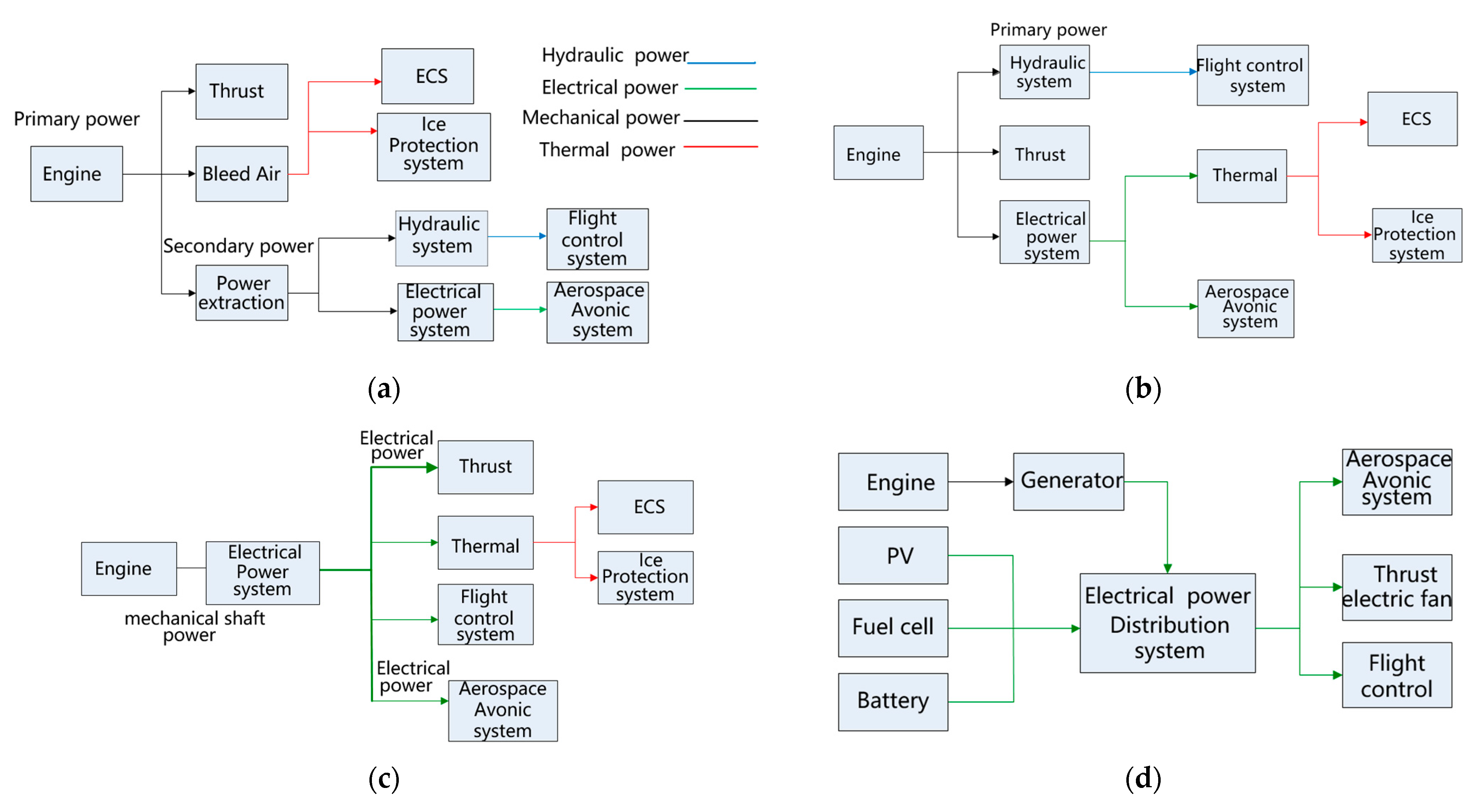
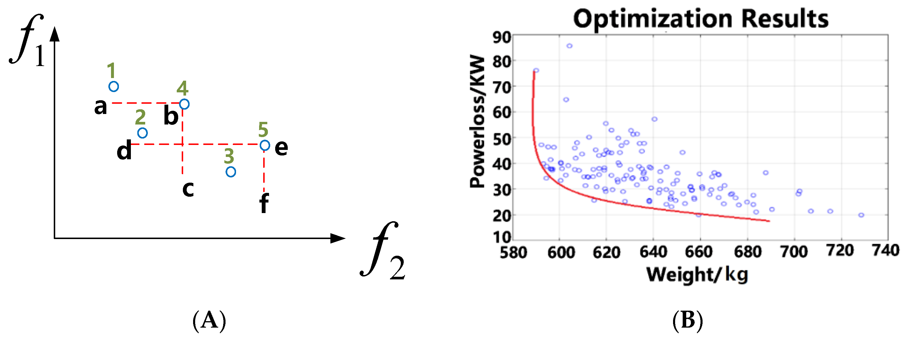
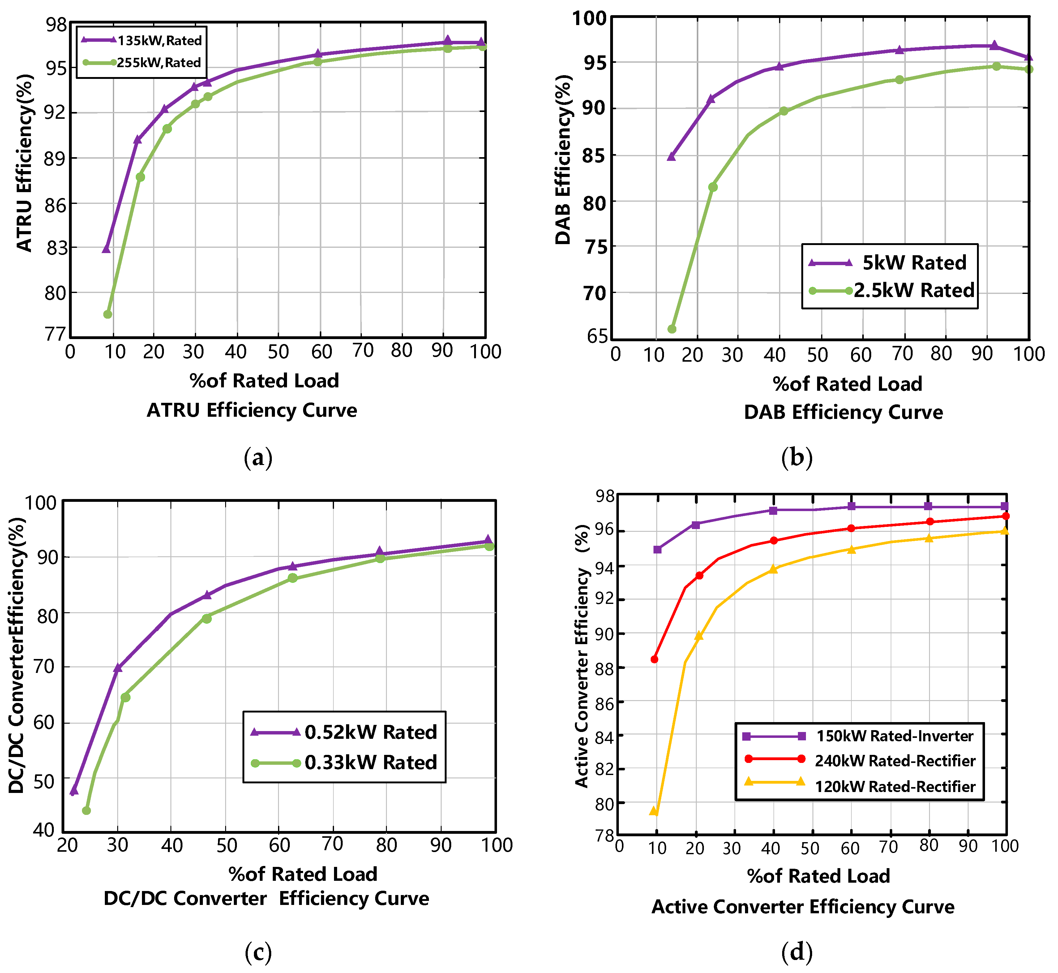
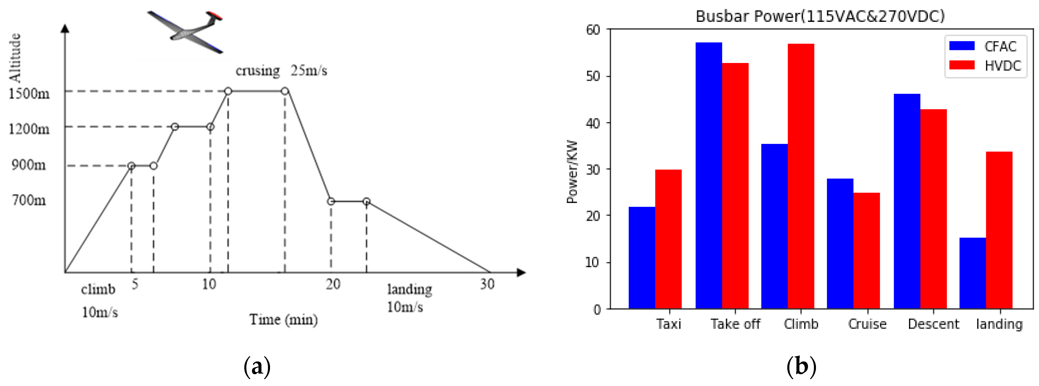
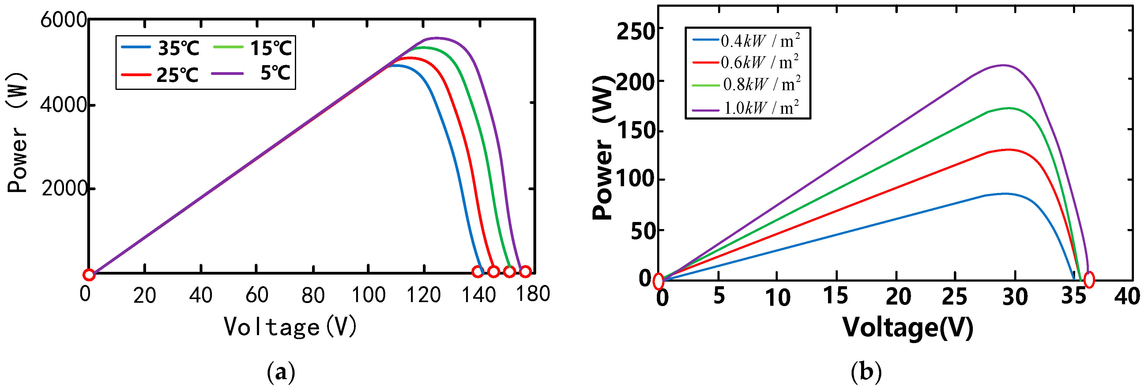
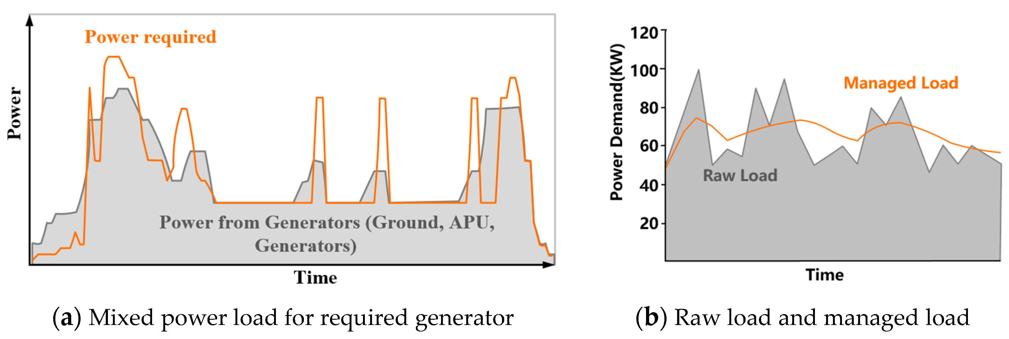
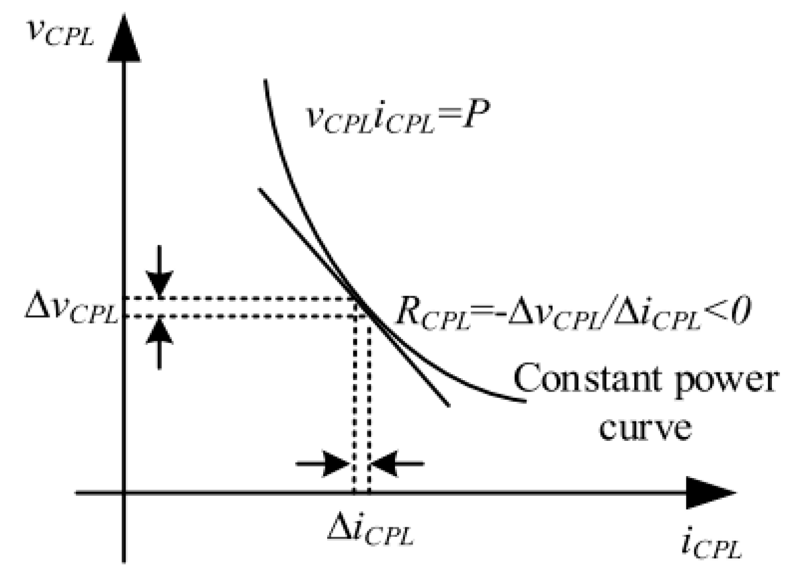
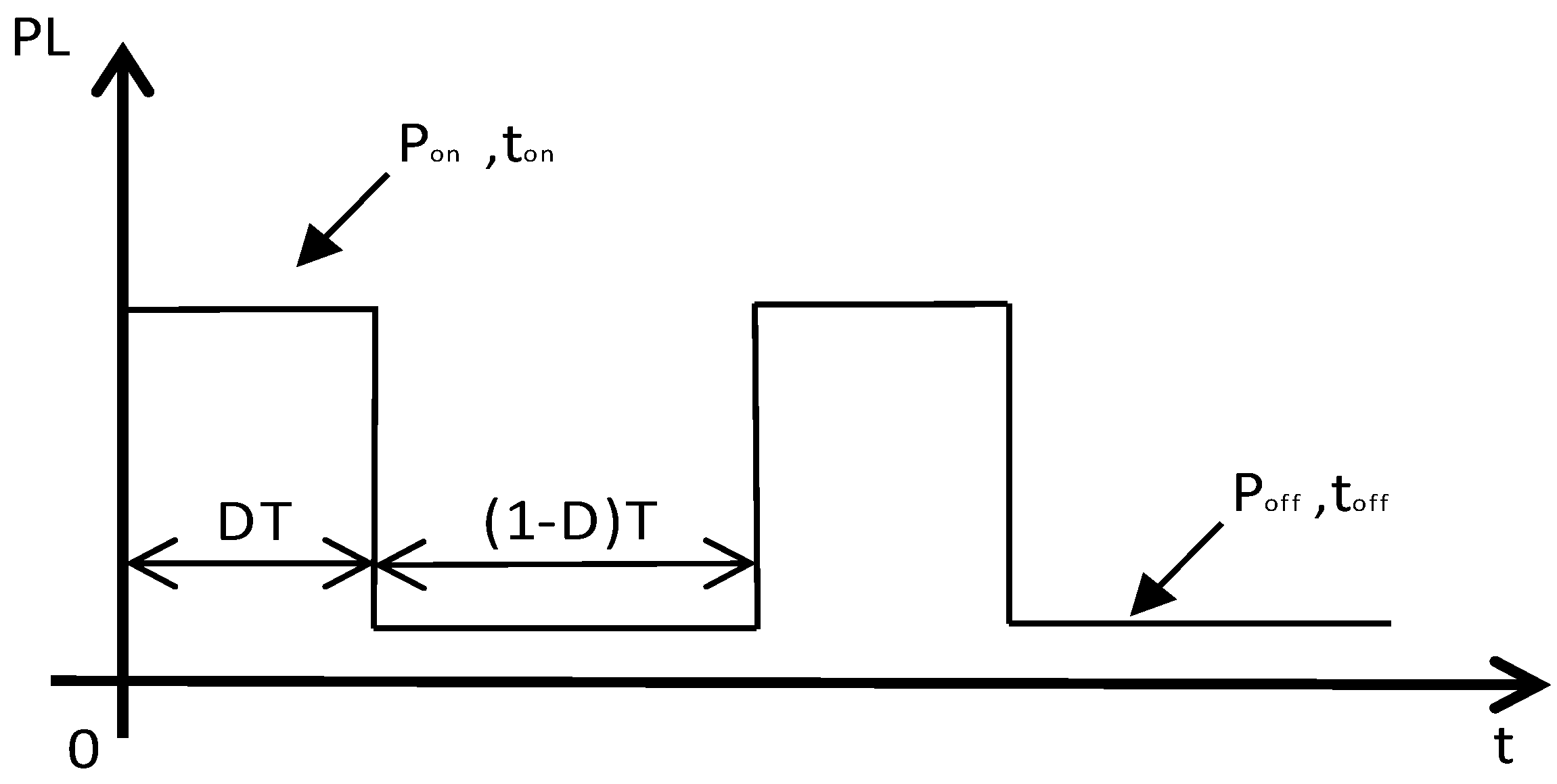
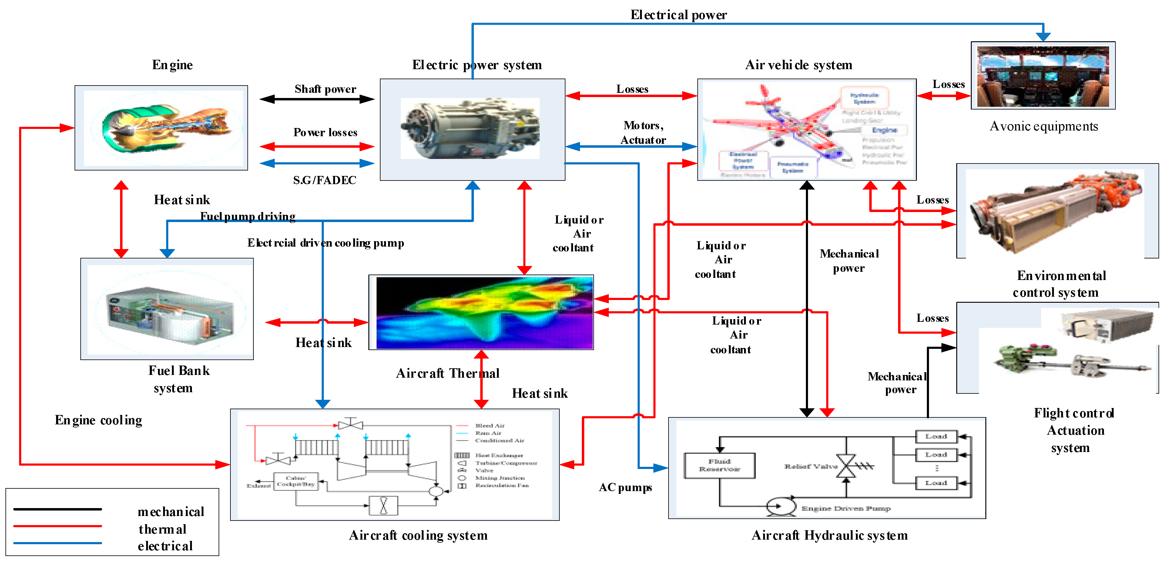
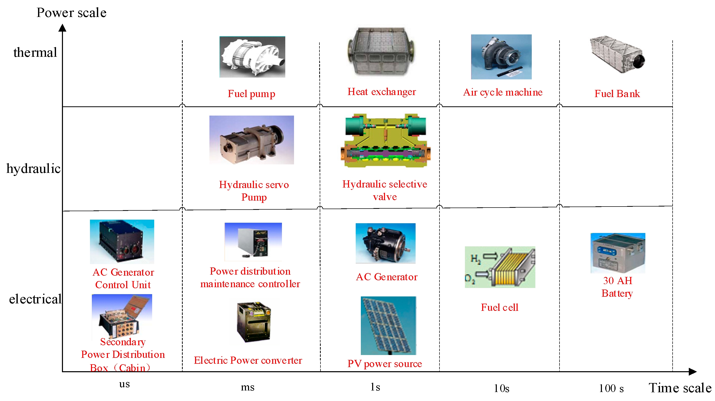
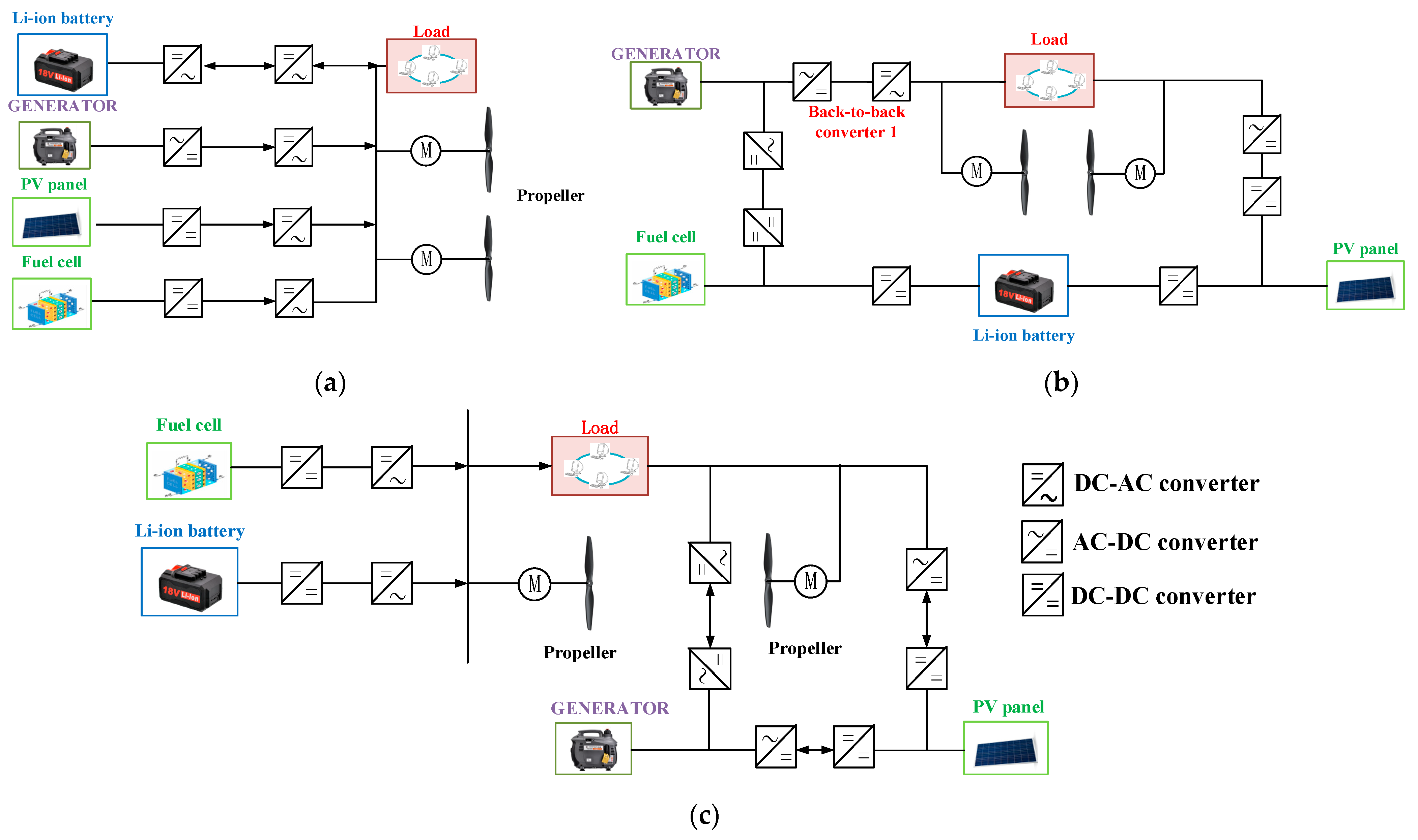
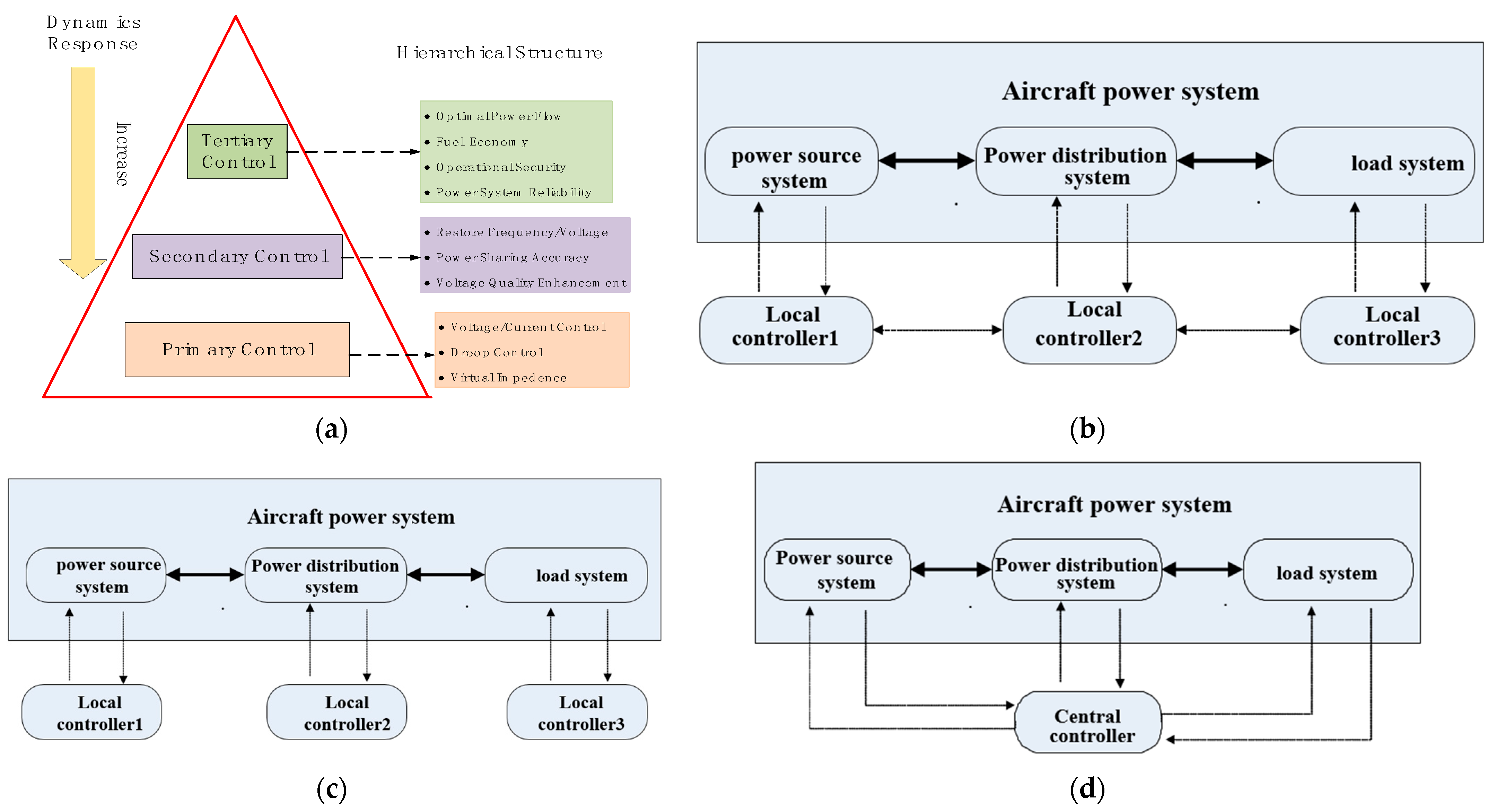
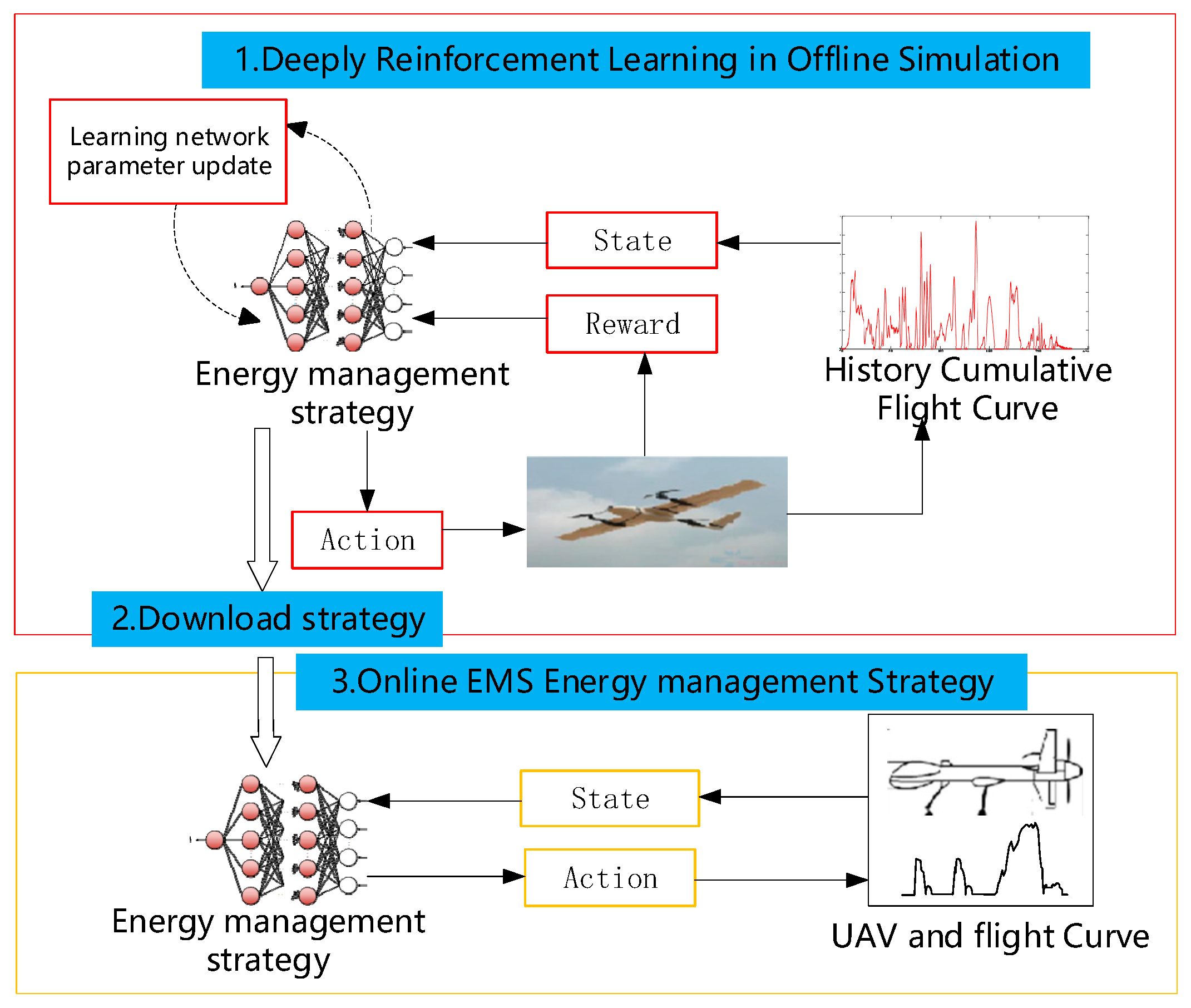
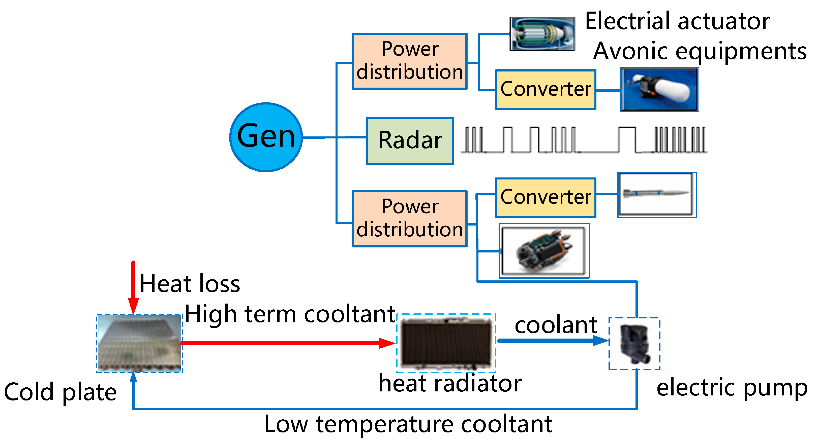
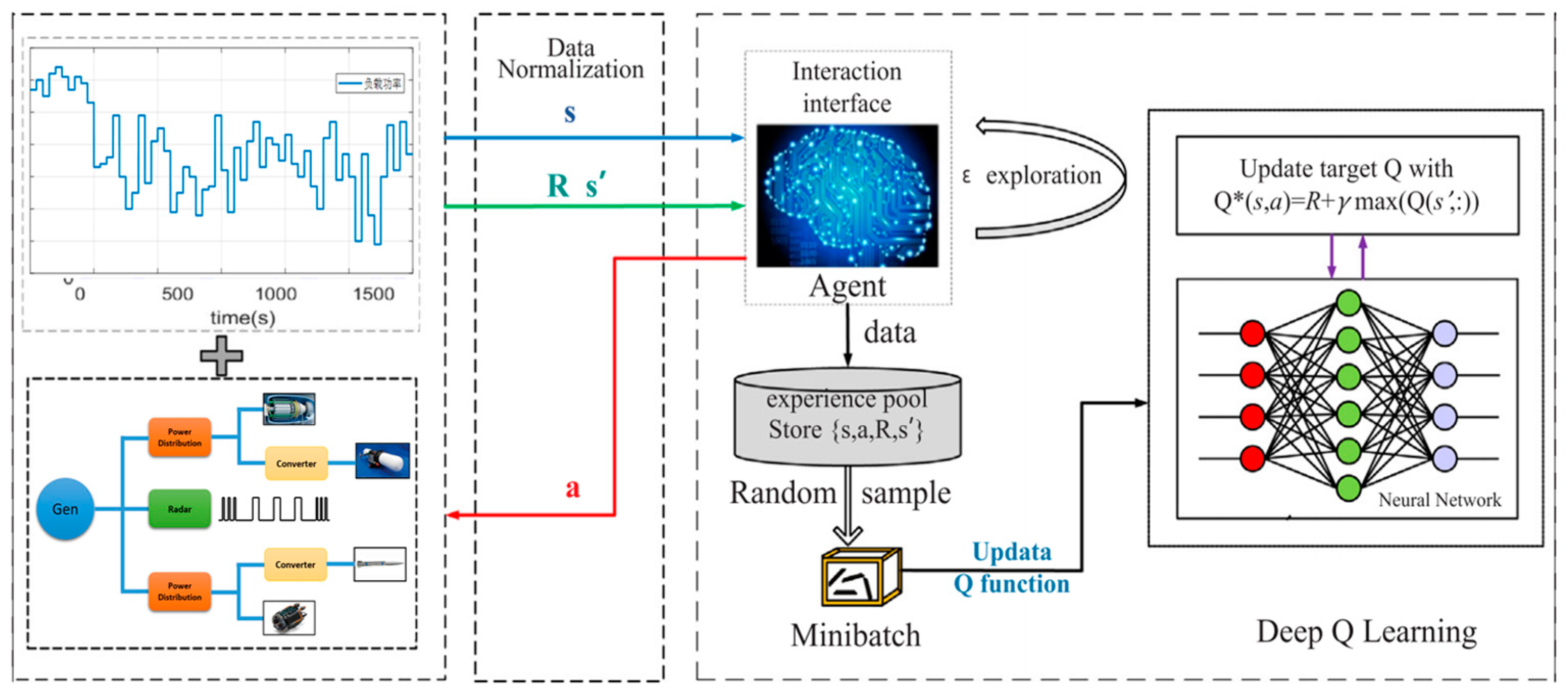
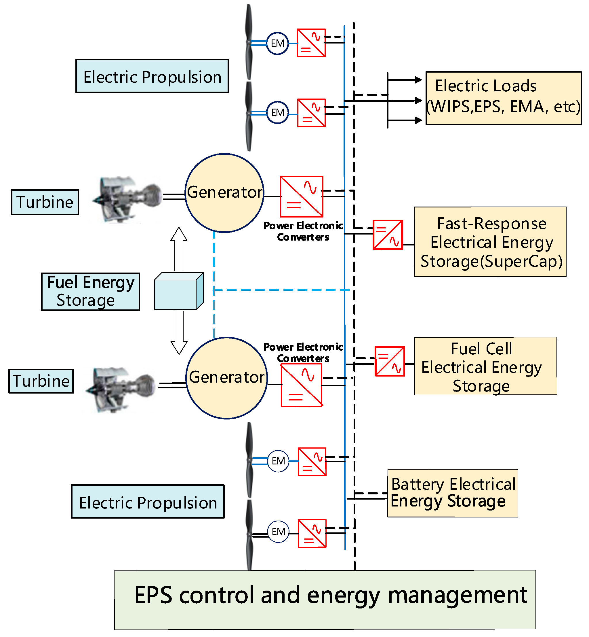
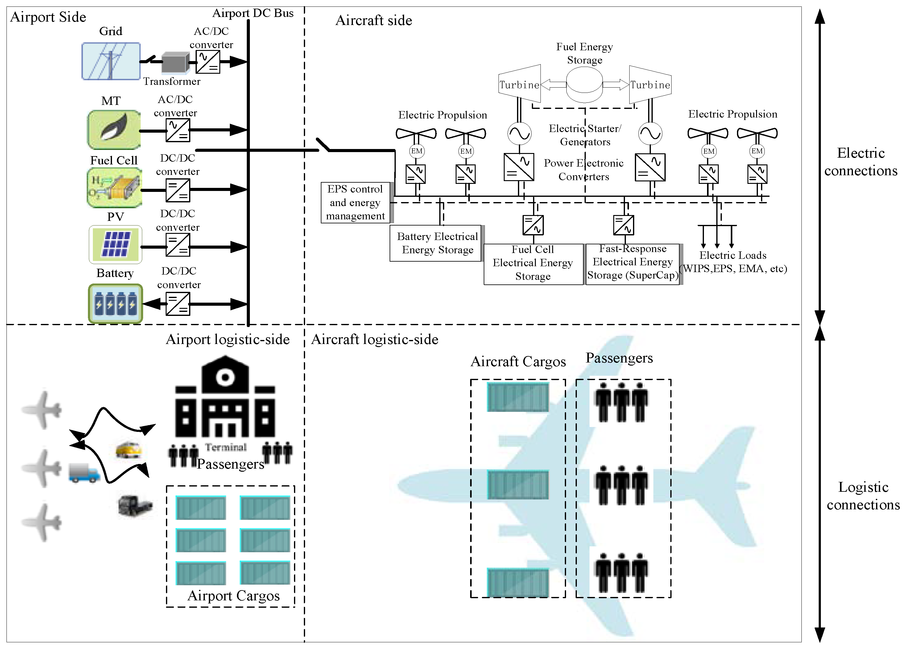
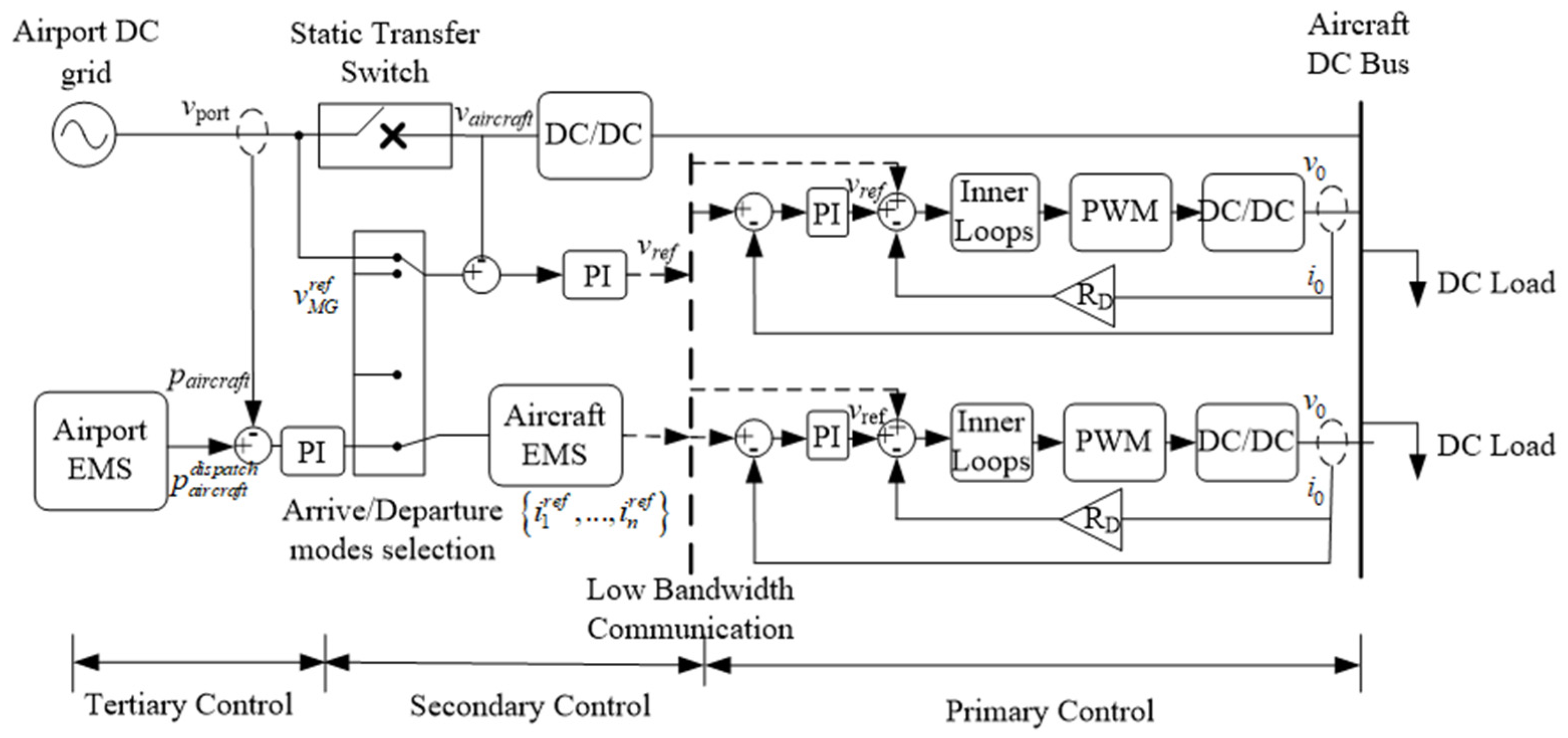
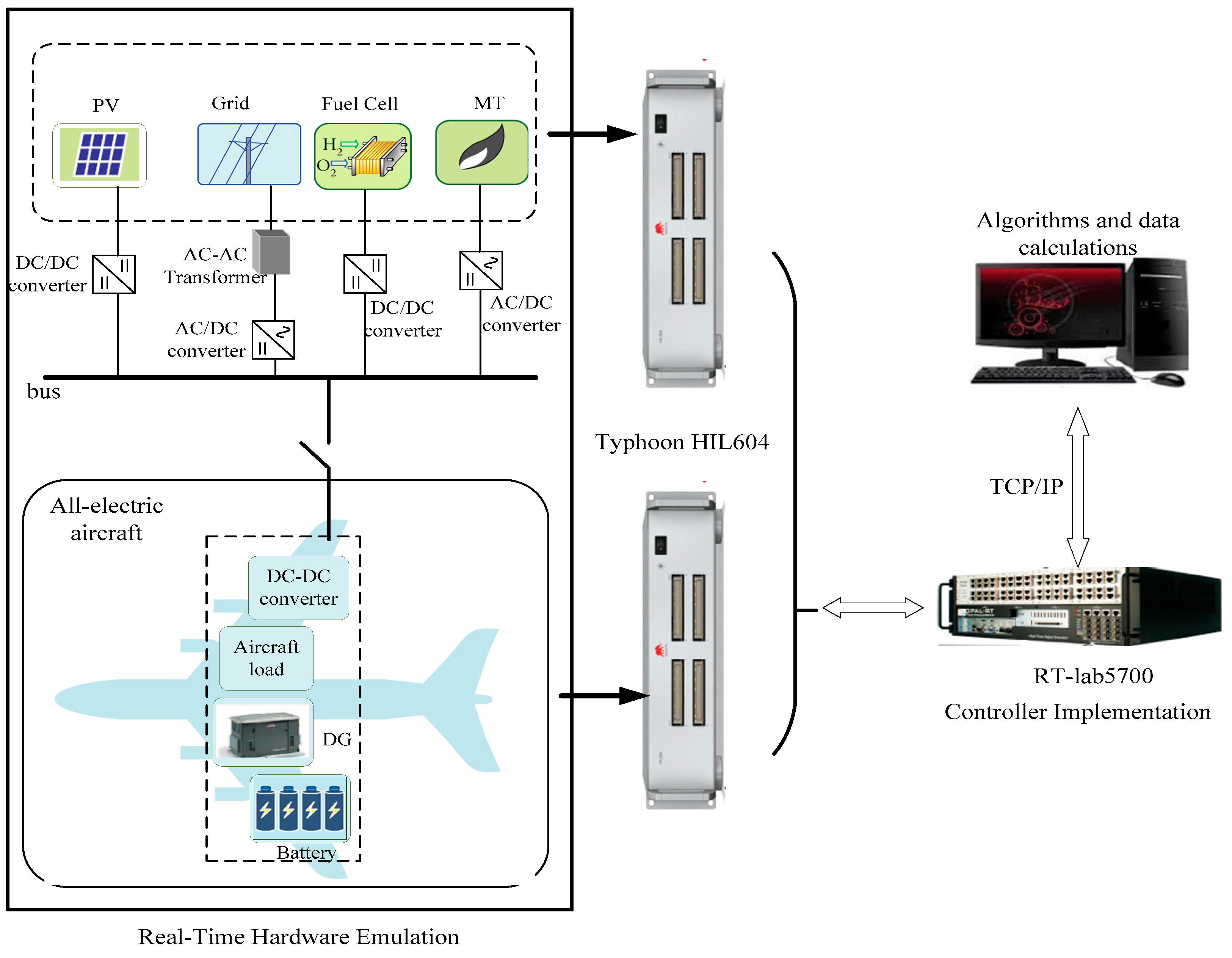
Table 1.
Optimization index of different electric power architecture.
| Energy and Power Architectural Form | Performance Index of Optimization Function |
|---|---|
| All types of electric power system architecture | The highest overall efficiency of the power system |
| Strong robustness, reliability, and fault tolerance | |
| Minimal emissions of pollutants such as carbon dioxide | |
| Lithium battery, fuel cell hybrid electric propulsion architecture | The longest service life of lithium batteries and fuel cells |
| Fuel cell, oil gas, battery hybrid-electric propulsion architecture | Minimization of fuel or hydrogen consumption |
| Solar and fuel cell electric propulsion architecture | Longest flight range and flight time |
Table 2.
The summarized energy and power management methods for different aircraft platforms.
| Energy and Power Management Strategies | Aircraft Platform | Control and Optimization Objective | Features | Reference Paper |
|---|---|---|---|---|
| Rule-based | UAV, Aircraft APU system; More electric engine | Fuel or hydrogen consumption minimization | State machine; Power distribution based on expert experience | [50,51,71,89,90,91] |
| Fuzzy logic | UAV, Aircraft APU system, Aircraft HVDC | Hydrogen consumption minimization, voltage stability | FLC to specific flight profile or APU load demand | [53,71,89,92] |
| Hybrid electrical propulsion UAV | Fuel Consumption minimization | Equivalent consumption minimization strategy plus FLC | [93] | |
| Fuel cell UAV | Hydrogen consumption minimization, voltage stability | PSO+FLC | [81,87] | |
| Meta-heuristic | Aircraft emergency power system | Less hydrogen consumed; Optimal life time of electrical sources; | Artificial bee colony algorithm; Grey wolf optimization algorithm | [94] |
| MPC-based | Hybrid-electrical propulsion aircraft | System efficiency Fuel-consumption Voltage stability | Conventional MPC | [66,95] |
| Aircraft APU system | System efficiency | Traditional MPC | [89] | |
| Aircraft distributed power system | Minimum switching of generator and power load shedding; power quality, minimization of THD | Stochastic MPC; INA-SQP MPC | [47,96] | |
| Aircraft energy storage system | Reduce the DC bus voltage transient; Minimization of current draw from the storage system | SQP solver | [78] | |
| MEA power system with PV | Stability of system; Steady and transient state Current control | FCS MPC + stability constraining dichotomy solution | [97] | |
| MEA Electrical power system and Fuel thermal management system | Fuel consumption minimization; Increased capability of thermal management | Hierarchy MPC control with thermal coupling | [98,99] | |
| Engines and electrical generation system in MEA | Fuel efficiency and emissions | Distributed MPC with ADMM algorithm | [86] | |
| DP | Small-size aircraft, UAV | Fuel consumption minimization | Lookup-table | [65] |
| Parallel hybrid-electric aircraft | Total mission fuel burn minimization over the flight envelope | Offline optimization | [100] | |
| MEA power distribution system | Power loss minimization Amount of switching is minimized | Optimal reliability configuration | [48] | |
| Adaptive energy management (ADP or RL) | more electrical aircraft with pulse load | Lowest possible rate of change of the main source of power or offers a fixed minimum rate of change in power | Integrated variable rate-limit of power | [101] |
| Electrical power system in MEA | Optimization problem for power scheduling and allocation; minimize the fluctuation in power generation system; bus voltage regulation | Optimal adaptive control with MIQP, off-policy integral reinforcement learning | [82] | |
| Electrical emergency power system in MEA | Fuel consumption and overall efficiency optimization under the false data injection attack and denial of service attack from the critical measurements | Adaptive neuro-fuzzy inference system and specific fuzzy deep belief network | [102] | |
| Fuel cell electric UAV | Hydrogen consumption and battery lifetime | ADP and RL | [103] | |
| Power decoupling methods based on filter frequency | Aircraft Fuel cell and battery hybrid emergency power system | Voltage stability; Minimization of power loss; Extend the lifetime of power source; | Slow power response for fuel cell; Fast power response for battery | [11] |
| Optimal control and PMP | All electrical Propulsion Aircraft | Combination of time-related and battery charge costs | Pontryagin’s Minimum Principle | [83] |
| Hybrid electrical aircraft | Minimization of fuel consumption with thermal management for the battery pack | Pontryagin’s Minimum Principle | [104] | |
| Combinatorial optimization | MEA aircraft ECS system | Electrical consumption minimization | MILP | [46] |
| MEA Power distribution | Three-phase load balanced; Increase the lifetime of power converter | Nonlinear optimization; Convex optimization | [51,105] | |
| UAV | Flight mission planning and recharging optimization | SDP and QP | [106] | |
| UAV | Minimize the fuel consumption (FC) and polluted gas emission | Bender decomposition-based method; (MIQP) | [107] | |
| MEA power generation and distribution system | Optimal power allocation; Optimal generator sizing | MILP | [108] | |
| MEA low voltage distribution system | Load allocation on the EPS | Knapsack problem | [67] | |
| Droop control methods | Aircraft HVDC system | DC bus stability | Active stabilization methods, load sharing | [70,109,110] |
| Aircraft APU | Dynamic response for power allocation optimization | Virtual impedance Droop control | [72] |
Publisher’s Note: MDPI stays neutral with regard to jurisdictional claims in published maps and institutional affiliations. |
© 2022 by the authors. Licensee MDPI, Basel, Switzerland. This article is an open access article distributed under the terms and conditions of the Creative Commons Attribution (CC BY) license (https://creativecommons.org/licenses/by/4.0/).
Share and Cite
MDPI and ACS Style
Lei, T.; Min, Z.; Gao, Q.; Song, L.; Zhang, X.; Zhang, X. The Architecture Optimization and Energy Management Technology of Aircraft Power Systems: A Review and Future Trends. Energies 2022, 15, 4109. https://doi.org/10.3390/en15114109
AMA Style
Lei T, Min Z, Gao Q, Song L, Zhang X, Zhang X. The Architecture Optimization and Energy Management Technology of Aircraft Power Systems: A Review and Future Trends. Energies. 2022; 15(11):4109. https://doi.org/10.3390/en15114109
Chicago/Turabian StyleLei, Tao, Zhihao Min, Qinxiang Gao, Lina Song, Xingyu Zhang, and Xiaobin Zhang. 2022. "The Architecture Optimization and Energy Management Technology of Aircraft Power Systems: A Review and Future Trends" Energies 15, no. 11: 4109. https://doi.org/10.3390/en15114109
Note that from the first issue of 2016, this journal uses article numbers instead of page numbers. See further details here.