1. Introduction
China’s coal reserves are mainly distributed in northwest regions, among which those in Shanxi, Shaanxi, Inner Mongolia and Xinjiang are the most abundant and account for nearly 70% of China’s total coal resources [
1]. With the depletion of coal resources in east China, the focus of coal mining has gradually shifted to northwest China with an arid and semi-arid climate. Northwest areas are already the main coal producing areas in China, where the proved reserves make up more than two-thirds of the country’s total [
2,
3,
4].
However, the main coal producing areas in northwest China feature a dry climate, sparse vegetation, land desertification and water shortage. The water resources account for only 3.9% of the total water resources [
5]. The Quaternary Salawusu formation aquifer is the only shallow aquifer with the significance of being a residential and ecological water supply [
6,
7,
8]. Large-scale and high-intensity coal mining has resulted in the movement and destruction of the overburden, and the fractures in the overlying layers are prone to occur. If the fissures act as a hydraulic exchange zone between the shallow aquifer and the goaf, a large amount of water in the aquifer will flow into the mined-out area, breaking the original supplement, runoff and discharge balance state of the aquifer, and thus lead to sharp water table lowering and large-range water resource loss [
9,
10]. Taking the water level statistics of the Yu-Shen coal area in Shaanxi Province as an example, an area where the water level drop is greater than 8 m and has exceeded 650 km
2, more than 70% is directly induced by high-intensity mining, which directly exacerbates the deterioration of the regional ecological environment [
11]. In-depth research on water resource preservation and conservation in the mining areas has been conducted locally and abroad. Foreign experts analyzed the relationship between the mining-induced groundwater flow and the overlying strata migration and fracture development [
12,
13,
14]. They studied the impact law of longwall mining on the water level of the overlying aquifer and the surrounding water environment, and evaluated the potential impact of mining on the surface and groundwater [
15,
16,
17,
18]. Additionally, the mining method was optimized according to the measured data of mining-induced groundwater level fluctuation obtained by the groundwater monitoring network [
19,
20,
21,
22]. The surface water and shallow aquifer were therefore protected from interference or damage, contributing to the realization of the sustainable and coordinative development of coal resources and shallow water resources [
23,
24,
25]. Aiming at the problem of shallow surface water leakage during the process of coal mining in the Yu-Shen mining area, domestic scholars put forward the concept of water-preserving mining, and expounded its scientific connotation systematically [
26]. They studied the stability of a water-resisting layer beneath the shallow water, and analyzed the relationship between the water table lowering and mining magnitude [
27,
28,
29]. Water conservation mining methods, such as backfill mining, harmonic mining, partial mining, curtain grouting, overburden bed separation grouting and coal mine underground reservoir construction, have been proposed and put into implementation [
30], the first of which is currently the most effective one for water preservation during coal extraction. Backfill mining includes longwall and shortwall backfill, and the former is confronted with the problems of insufficient filling time and filling space, and mutual impact and restriction between extraction and filling [
31,
32,
33,
34,
35]. In view of the aforementioned problems, a CECB water preservation mining method which can realize the parallel and coordinated operation of mining and filling was proposed, contributing to mitigating the overburden migration and thus achieving extracting coal body beneath the shallow water [
36,
37,
38,
39,
40,
41,
42].
On the other hand, the annual output of fly ash in 2018 in China exceeded 550 million tons, and the total storage volume was more than 3 billion tons [
43]. Large quantities of fly ash produced by the combustion of coal in power plants have been causing air and soil pollution [
44,
45]. Harmless and large-scale treatment of fly ash is therefore necessary and urgent. Meanwhile, CO
2 emissions from coal consumption account for 72% and 28% of Chinese and global CO
2 emissions, respectively. The combustion of 1 ton of coal produces 2.4 tons of CO
2 [
46]. In 2018, China’s coal combustion emitted around 7.2 billion tons of CO
2 and it strives to achieve a carbon peak by 2030 and be carbon neutral by 2060 [
47,
48,
49,
50]. In this context, carbon sequestration has attracted the attention of the Chinese government and emphasis has been put on it. However, the total amount of carbon sequestration is only about 300,000 t/a, which is not enough to provide effective support for this goal [
51]. In order to effectively cope with the continuous increase in CO
2 emissions and fly ash, sequestrating CO
2 to fly ash and developing CO
2 mineralized filling body (CMFB) is one of the most ideal and appropriate options [
52]. CMFB is employed and injected into the mined-out area of mining roadways (MRs) of the CECB mining method to realize CO
2 sequestration. In the meantime, solid CMFB replaces coal body to support the roof and mitigate the migration of the overburden and water-resisting layer, which can help to preserve the valuable shallow water resources and achieve green and sustainable development of coal areas. However, the mechanical properties of CMFB with various material ratios, and the influence of CMFBs on mining-induced aquifuge stability, which is of great importance for shallow water preservation, are not clear. The control mechanism of CMFBs on the shallow water level while using the CECB mining method requires further study. Further study to develop CMFB with different material ratios to not only sequestrate CO
2 but preserve and conserve the shallow water level, and thus protect and maintain the surface ecological environment, is necessary.
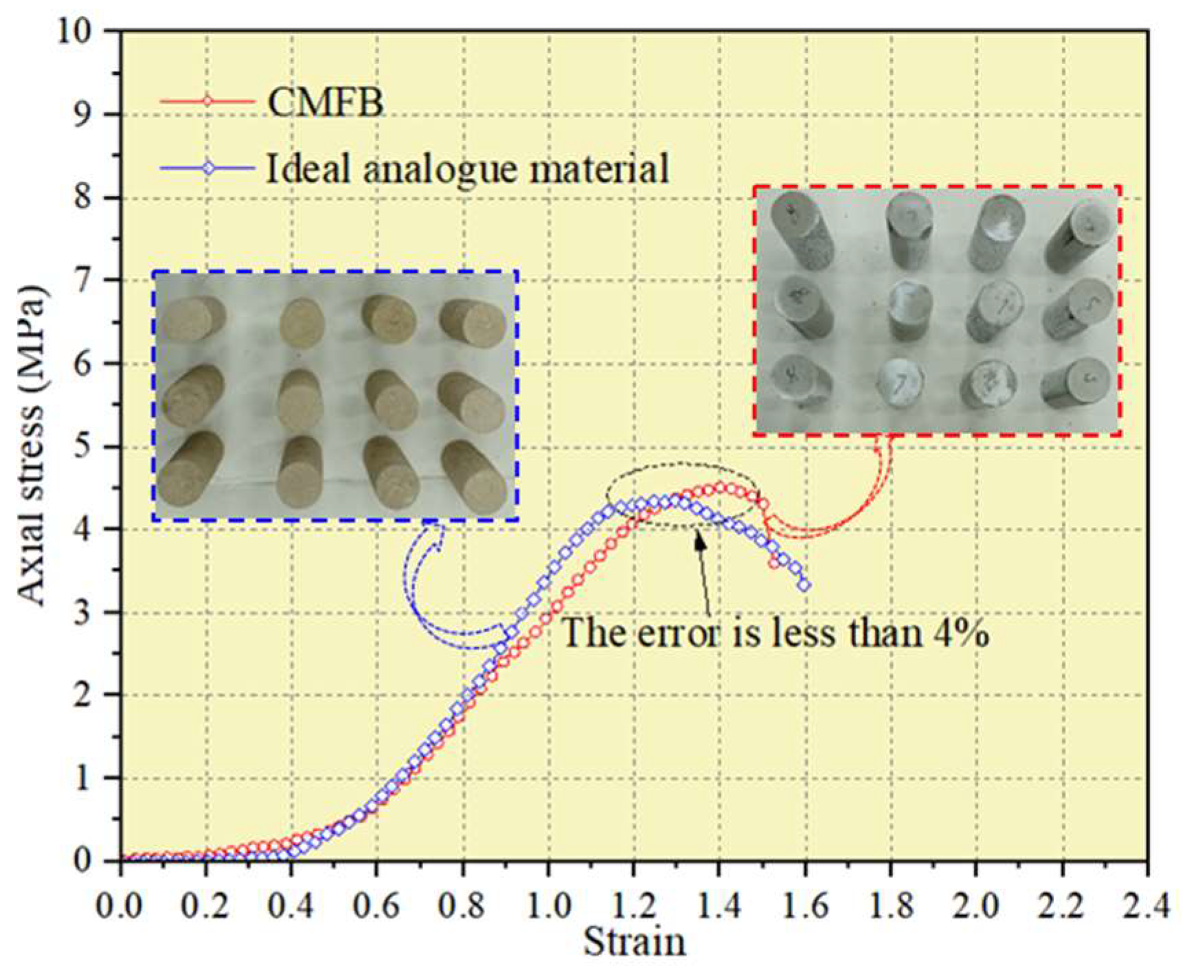
In view of the aforementioned problems, we carry out a prospective study on the development and application of CMFB at ambient pressure and temperature, with fly ash as aggregate and silicate additives, cement and CO2 gas as accessories. The indoor mechanical parameter test of the CMFB with different curing times and material ratios is carried out. Based on the stress–strain curve of the testing results, the proportion of analogue materials of CMFB is optimized and determined, and the physical similarity simulation of overburden movement while using the CECB mining method and CMFB is implemented. Additionally, the CMFB strain-softening parameters in the numerical simulation are calibrated systematically, and the FLAC3D numerical calculation model is then constructed to simulate the aquiclude movement corresponding to CMFB with different fly ash contents while using the CECB mining method. Subsequently, the fluid–solid coupling module is employed to reveal the influence mechanism of different material ratios of CMFB on the variation law of the shallow aquifer water level. This paper proposes a concept that employs the CECB water preservation coal mining method to sequestrate CO2 and replace the coal body to support the roof, contributing not only to the harmless treatment of fly ash, but also the achievement of shallow water preservation mining. The research results can provide a theoretical reference and guidance for the realization of CO2 mineralized filling in mines in the future, which is conducive to green and sustainable mining.
2. CECB Mining Method to Sequestrate CO2 and Preserve Shallow Water
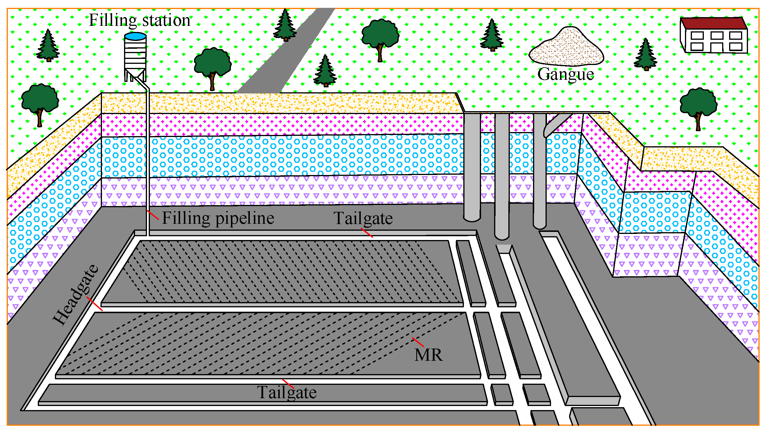
The confined room is necessary for the CO2 mineralization process and CECB mining is an ideal mining method to provide a closed space for CMFB since the MRs features good airtightness and flexible and adjustable dimensions. The CO2 can be mineralized with the solid waste in the long run and water preservation can be realized by optimizing the material ratio of the CMFB and the dimensions of MRs.
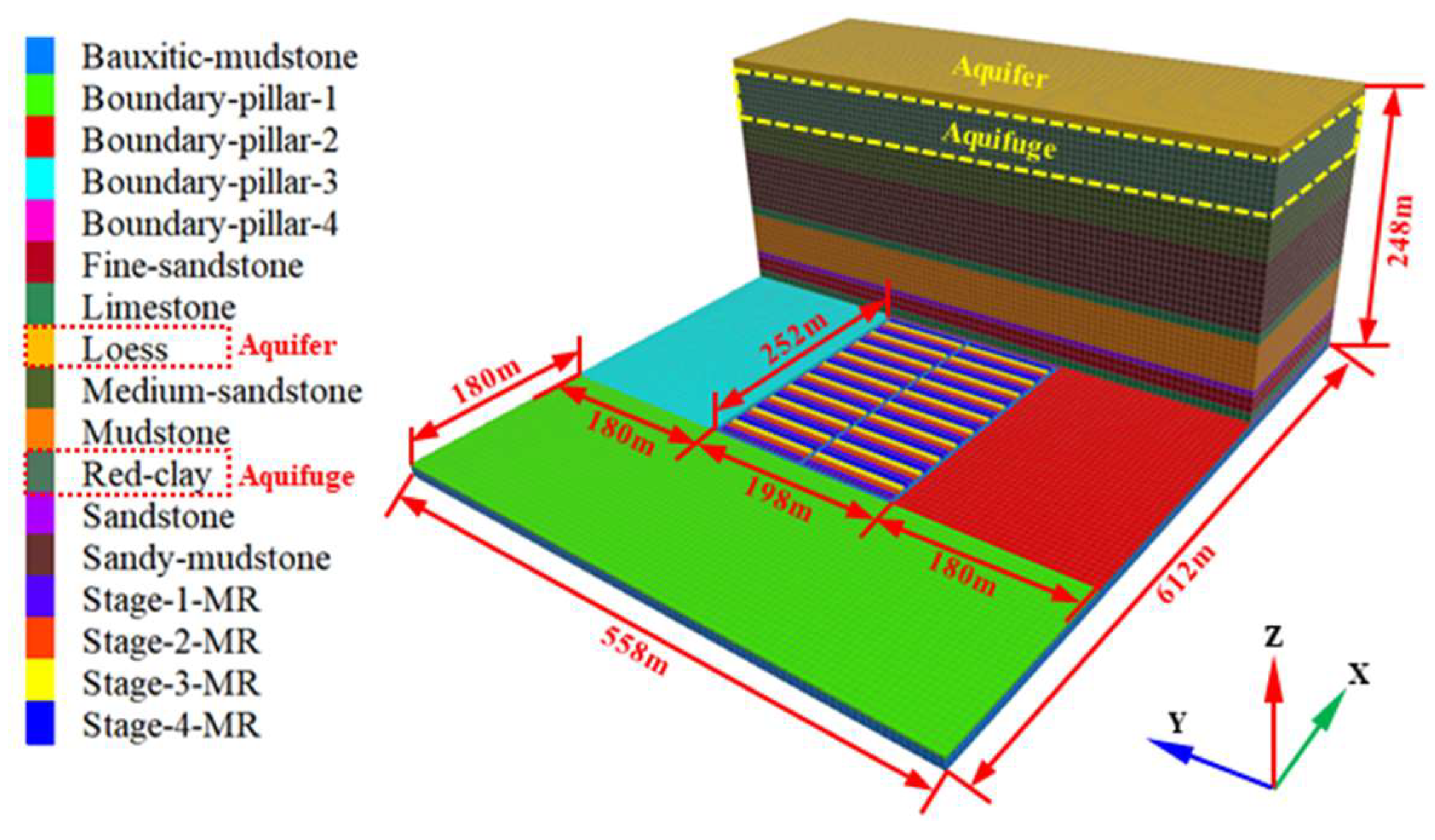
Prior to CECB mining, the mining panel is divided into many MRs along two sides of the headgate, and the MRs are then allocated to different mining phases (generally 3–5). The three-dimensional sketch map of the MR arrangement of the CECB method is shown in
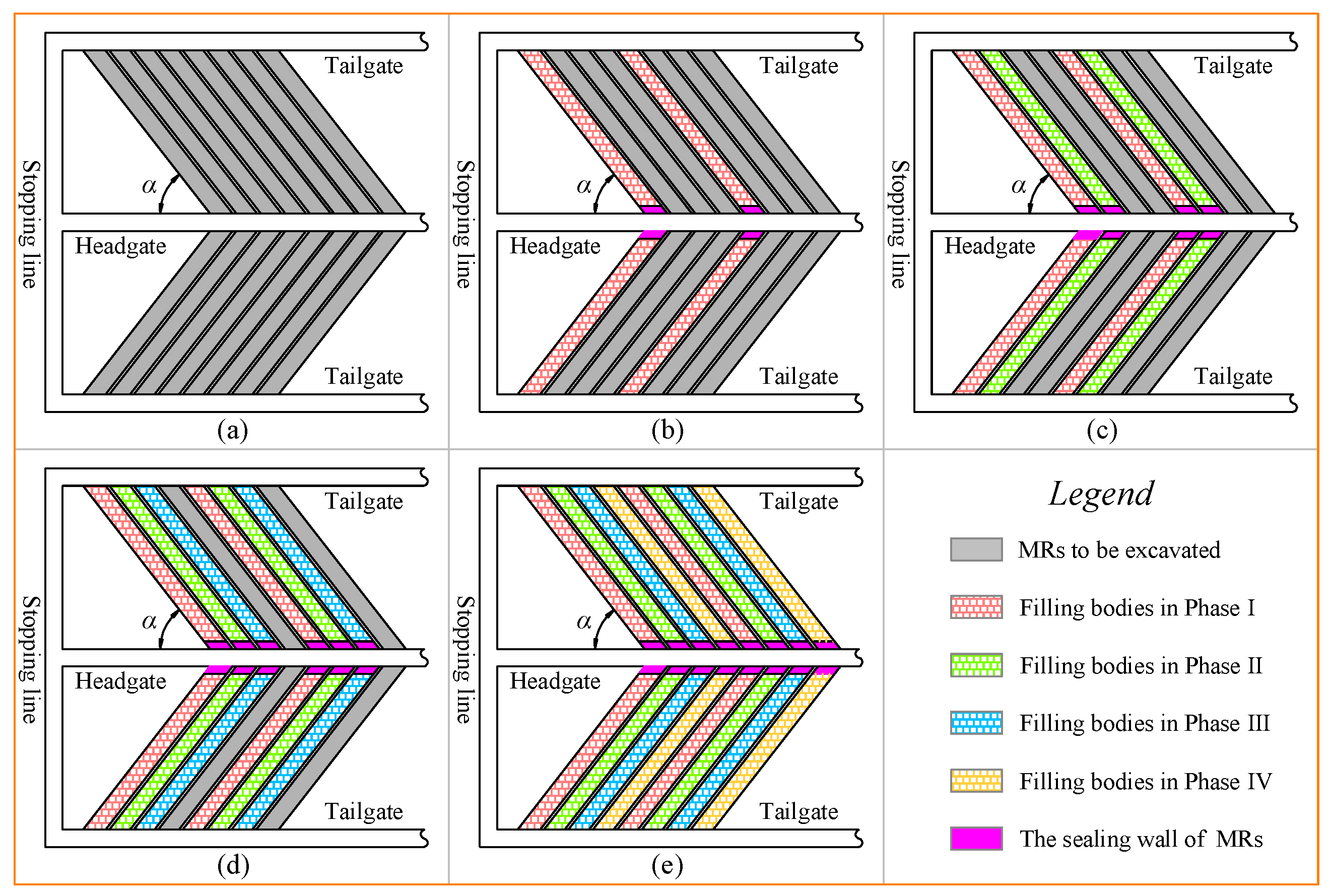
Figure 1. The schematic map of the mining processes of the CECB method is shown in
Figure 2.
In order to mitigate the mining disturbance and thus to make the CMFB conducive to being injected, the length of the MR is generally less than 150 m while the width varies from 4.0 m to 7.0 m. The angle α between the MR and the headgate usually ranges from 40 to 60°. Skip extraction enables the roof of each mined-out MR to be supported by the coal body or the CMFB which has reached the designed strength. Hence, the drastic overburden deformation caused by insufficient longwall filling time can be averted. This method avoids the problem of uncoordinated operations between mining and filling during the longwall filling process. In addition, skip mining and filling make it feasible for the CMFB to stay in the three-dimensional stress state, which can increase the support strength of the filling body before it reaches the final strength. Both sides of the MRs, having been extracted, are always coal body or filling body that have reached the designed strength, which is conducive to controlling the migration and deformation of the overlying strata. For the purpose of effectively mitigating the movement of the overlying layers and avoiding the instability of the aquifuge, each MR will be sealed by a sealing wall and backfilled immediately after it is extracted. The MRs in the second phase will be extracted and backfilled after all MRs in the first phase are mined and backfilled. Finally, coal body in the mining panel is completely substituted by the CMFB to support the roof and preserve the shallow water. The CO2 sequestration and coal extraction under shallow water bodies can be realized.
5. Numerical Simulation of Aquiclude Deformation Using CECB and CMFB
5.1. Construction of the Numerical Simulation Model
Fast Lagrangian Analysis of Continua (FLAC
3D), a three-dimensional finite difference program developed by ITASCA in the United States, is one of the most widely used pieces of numerical analogue software in underground mining and geological engineering. The physical similar simulation model only detects vertical displacement of the aquifuge while the horizontal displacement is too small to detect. In addition, only CMFB with 14 d curing time and 75% fly ash content was taken into consideration in the physical simulation, which cannot study the influence of CMFB with different material ratios on the migration and stability of the aquifuge. In order to supplement the undetected horizontal displacement and horizontal deformation of the water-resisting layer and verify the results of the physical analogue simulation, a FLAC
3D numerical calculation model was established to simulate the deformation and water table lowering of the aquiclude using CECB mining and CMFB with 14 d curing time and various fly ash proportions, as shown in
Figure 10. Based on the engineering and geological conditions of a colliery which are the same as the physical analogue simulation, the adjacent strata with similar lithology are properly simplified and merged, and 12 strata were identified from bottom to top. With due consideration of the boundary effect and full mining, the dimensions of the model are determined to be 612 m × 558 m × 248 m (X × Y × Z). The deformation and velocity of the four boundaries of the numerical model located at the starting and ending point of the
X and
Y axis remain immobile. Meanwhile, the boundary at the starting point of the
Z axis was fixed while the top surface was free without any restrictions.
The length of the four boundary coal pillars is 180 m. The mining panel whose dimensions are 240 m × 180 m (strike × dip) is surrounded by a haulage roadway with width of 6 m. The height and width of the MR are 2.6 m and 6 m, respectively. The CECB mining area is divided into four phases, and a total of 80 MRs are distributed on both sides of the main transportation roadway. There are 20 MRs in each phase, and skip and interval mining are adopted on the same side along the main haulage roadway. After one MR is mined, the next one on the other side of the main haulage roadway is extracted immediately and the mined-out MR is backfilled simultaneously. The third MR, which is 24 m (four times of the MR width) away from the first MR in the X direction, is extracted in the same way as the first MR. When the MRs in the first phase is mined and backfilled, the MRs in the second phase start being extracted and filled until all MRs in the four phases are extracted.
A Mohr–Coulomb constitutive model was chosen for the coal seam and its overlying and underlying strata. Therefore, it was employed to conduct uniaxial compression simulation tests of rock from various strata, so as to determine the mechanical parameters of different strata. The mechanical parameters of each stratum in the model are adjusted continuously, until the simulation results show good consistency with the stress–strain curve obtained from the laboratory test. The mechanical property parameters of various strata are listed in
Table 3.
5.2. Determination of the Simulation Parameters of CMFB
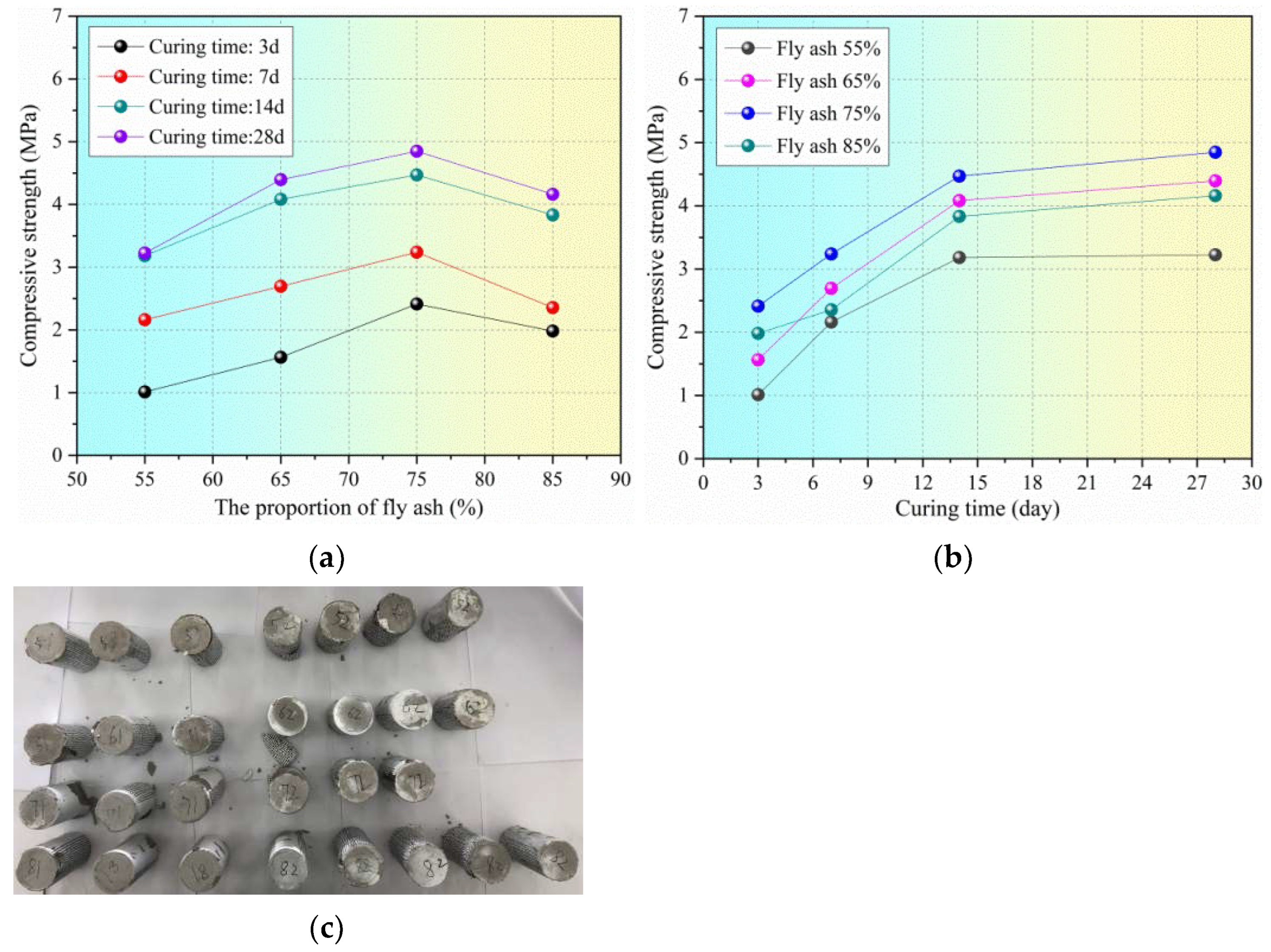
According to the research in
Section 3, the UCS of the CMFB increases rapidly when the setting time varies from 3 d to 14 d, while it slows down from 14 d to 28 d curing time, indicating that its strength and mechanical properties tend to be stable. Similarly, it takes 3 days to extract the coal body of each MR and 1 day to backfill it. The distance between the MR being extracted and the MR that was backfilled 14 days ago is generally greater than 70 m, so the filling body in the MR before day 14 is essentially immune to the current mining. It only bears the static load generated by ground pressure, and its mechanical environment is inclined to remain unchanged. Therefore, CMFB with 14 d curing time was selected for further analysis.
Moreover, the Young’s modulus of the backfill is a significant index reflecting its supporting capacity to the overburden and water-resisting layer. The filling body with large elastic modulus has better mechanical properties, which can effectively alleviate the deformation and fracture development of the overburden, so as to reduce the mining-induced impact on the shallow aquifer. Conversely, the backfill with small elastic modulus has greater deformation under the same load than that of the larger one, leading to the increasing subsidence of overlying layers. The water-flowing fractures will therefore be well developed, which may form a water-conducting channel between the mined-out area and the overlying aquifer and trigger a mine water inrush disaster. According to the UCS test results of CMFB from the laboratory, the proportion of fly ash has a great influence on the elastic modulus of the backfill, while the Poisson’s ratio is nearly unchanged and remains at 0.18 on average. The elastic modulus can be obtained by analyzing the slope of the stress–strain curve in the elastic deformation stage:
where
Ef is the elastic modulus of CMFB;
and
represent the stress of the starting and terminal point of the elastic deformation stage, respectively;
and
denote the strain of the origin and the end of the elastic deformation stage, respectively.
The bulk modulus and shear modulus can be calculated by:
where
Kf is the bulk modulus,
Gf is the shear modulus and
μ is the Poisson’s ratio.
Table 4 lists the mechanical property parameters such as elastic modulus, bulk modulus and shear modulus of CMFB with different fly ash contents after being cured for 14 days.
The strain-softening constitutive model was employed for CMFB. The cohesion, friction, dilation and tensile strength may soften after the beginning of plastic yield, while these properties are assumed to remain unchanged in the Mohr–Coulomb model. The strain-softening behavior of cohesion, friction angle and dilation based on plastic shear strain and plastic tensile strain were given in the form of specified table values, assuming that the two parameters in the table code are consecutive. The table values of these parameters were defined by the authors and they were obtained by back-analysis of the postfailure behavior of the CMFB.
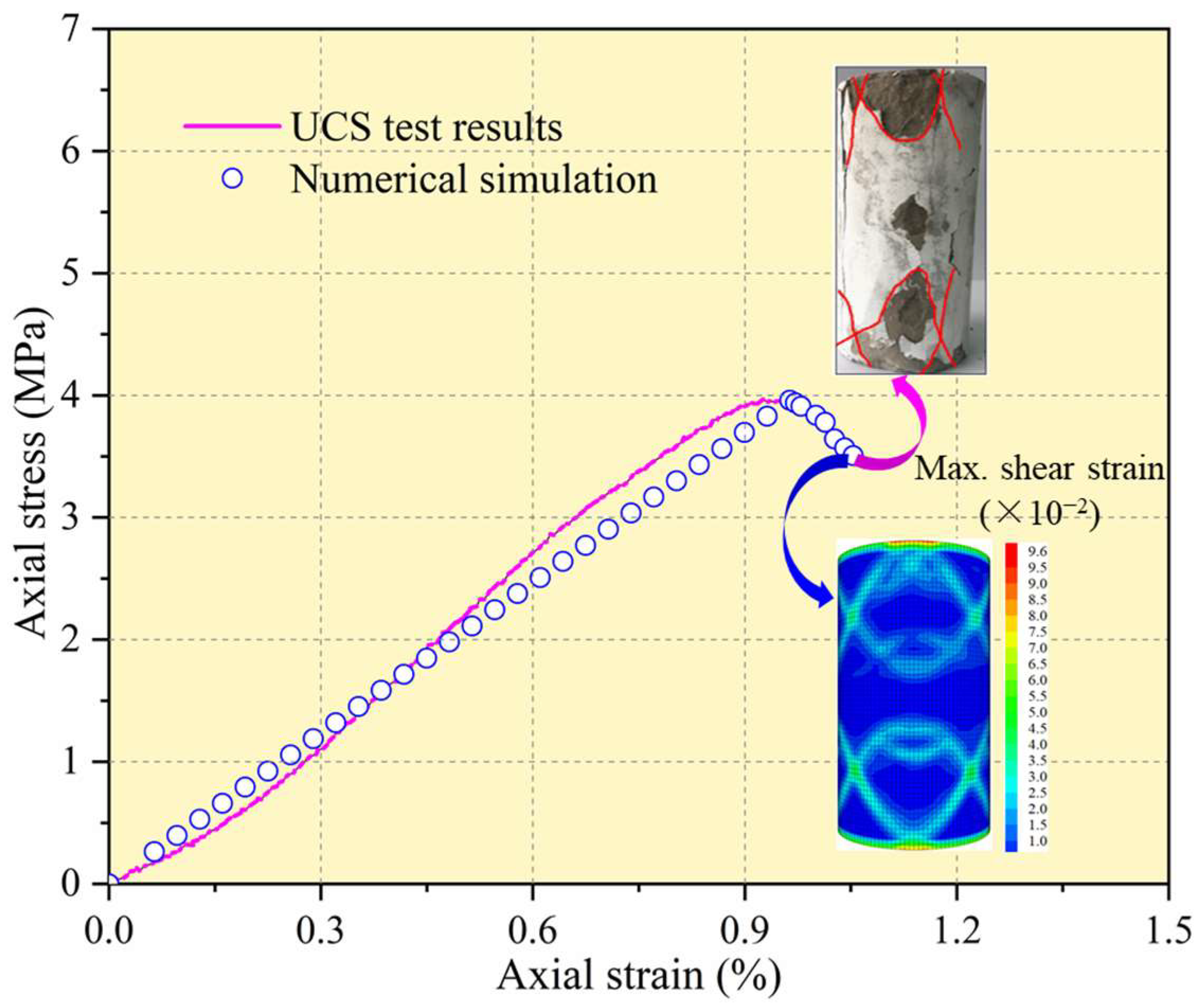
Taking the CMFB with 14 d curing time and 75% fly ash content as an example, the stress–strain curves of the UCS test from the laboratory test and the numerical simulation, as well as the failure form of the CMFB specimen and the maximum shear strain of the numerical simulation model, were compared and analyzed to systematically calibrate the aforementioned parameters of the strain-softening constitutive model. The calibration results are shown in
Figure 11.
This simulation considers that the cohesion and friction of CMFB decrease with the growing plastic shear strain, for the purpose of optimizing the numerical calculation steps. Their values are the residual value when the plastic shear strain is 0.01. The numerical results of the stress–strain curve and failure mode of the specimen were in good agreement with that of the indoor test results. In the numerical model, the maximum shear strain of the specimen shows an inclined and cross failure mode, which is consistent with that from the laboratory test. The parameters of the strain-softening model of the CMFB with various fly ash contents were calibrated and determined by the same means for the next study.
5.3. Mining-Induced Deformation of the Water-Resisting Layer
According to the calibrated strain-softening mechanical parameters of the CMFB, the numerical calculation of the movement of the water-resisting layer while using CECB mining and CMFB was carried out. After all MRs in the mining panel were extracted and backfilled and the maximum unbalance force was less than 10
−5 kN, the numerical calculation process ended. The bottom of the aquiclude was sliced, with the normal vector parallel to the
Z axis. Subsequently, the postprocessing software Tecplot was employed to extract the vertical and horizontal displacement values of the aquifuge in the section, and the extracted data were imported to another postprocessor Surfer. The Kriging interpolation method was adopted to draw the contour of the vertical displacement and the horizontal displacement of the aquiclude while using the CECB water-preserving mining. Then, the differential function built into the Surfer software was utilized and the contour map of the inclination, curvature and horizontal deformation of the aquifuge were derived, by executing the first-order and second-order differential functions embedded in the software.
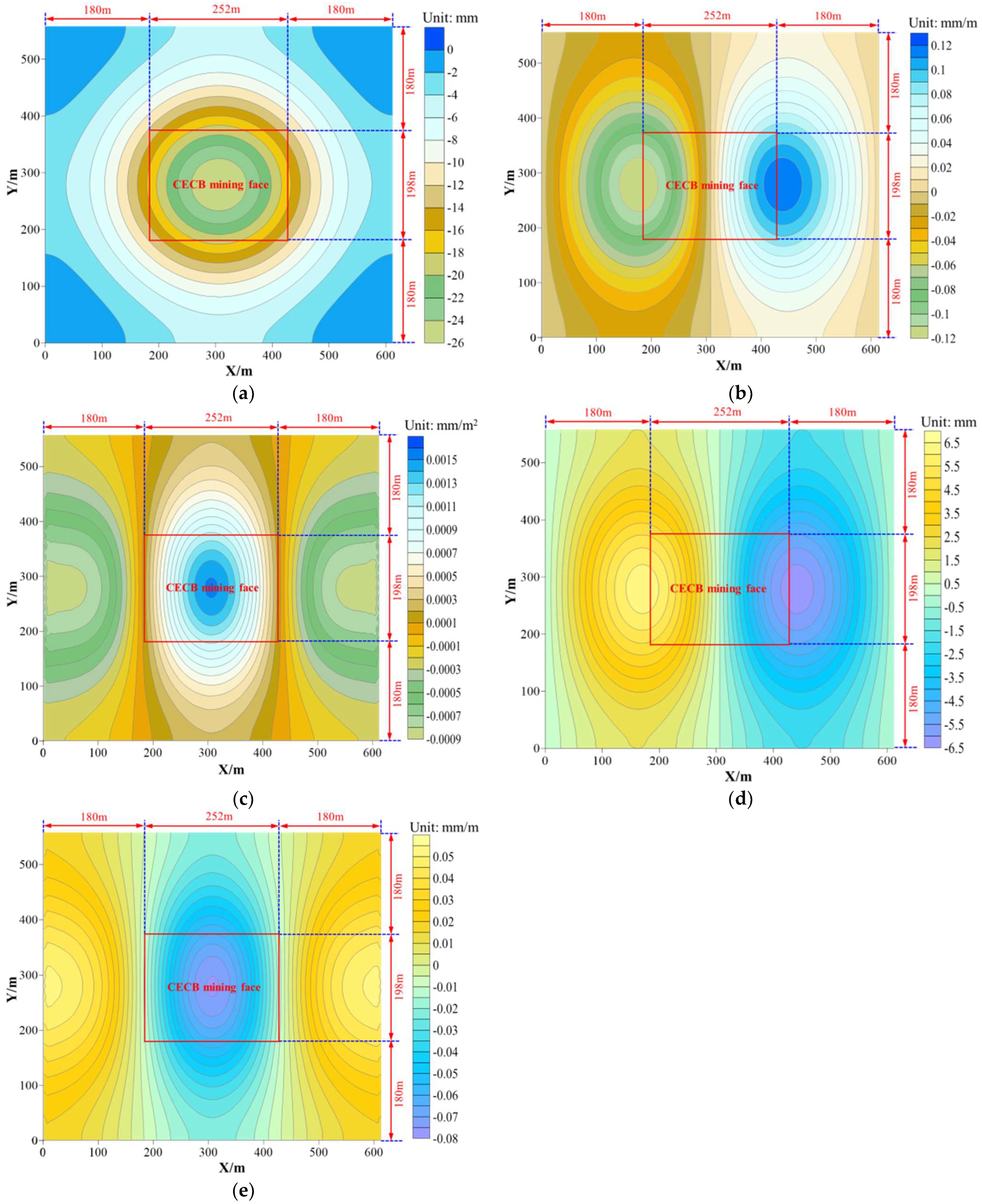
Figure 12 shows the contour map of the five deformation indicators of the overlying aquifuge while injecting the CMFB with a 75% fly ash proportion into the mined-out MRs.
Both the positive and negative deformation values can reflect the migration and damage degree of the rock stratum, so only the absolute value was analyzed. As
Figure 12 shows, under the conditions of injecting the CMFB, with the proportion of fly ash being 75%, into the mined-out MRs in the CECB mining panel, the maximum values of vertical displacement, horizontal displacement, inclination, horizontal deformation and curvature of the overlying aquifuge are 26 mm, 6.5 mm, 0.12 mm/m, the 0.08 mm/m and 0.0015 mm/m
2, respectively.
The maximum vertical judder of 26 mm is located in the middle of the aquifuge above the CECB mining panel and decreases up to its surrounding boundary, forming a typical subsidence basin. By contrast, the distribution of the tilt value is symmetrical with the perpendicular bisector of the X axis as the symmetrical point and the maximum values of 0.12 mm/m occur in the place of aquiclude over the two boundaries of the working face in the X direction, which is known as the open-off line and the stopping line. In addition, the maximum curvature of 0.0015 mm/m2 arises in the water-resisting layer above the center of the mining panel, which is similar to the vertical displacement. The lowest value is situated in the vicinity of the working face. Hence, the curvature decreases to the minimum value of 0.0001 mm/m2 first and then rises to 0.0009 mm/m2 in the boundary of the model. Furthermore, the contour map of the horizontal displacement is similar to that of the tilt, with the maximum size of 6.5 mm at the overlying aquifuge over both sides of the CECB face along the X direction. The maximum horizontal deformation of 0.08 mm/m is in the center of the aquifuge, indicating the high probability of the development of vertical tensile fractures.
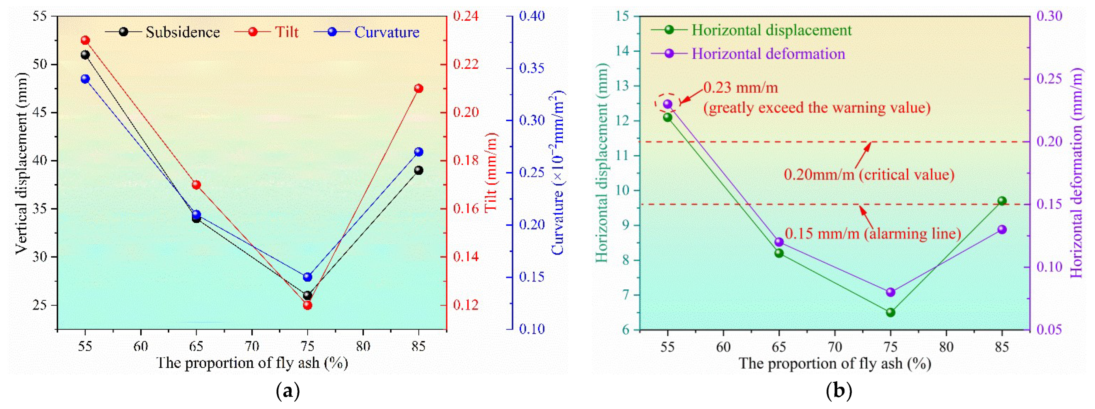
By using a similar method to the one above, the maximum values of the five deformation indexes of the water-resisting layer while using the CMFB with 55%, 65% and 85% fly ash were obtained, as shown in
Figure 13.
The maximum values of five deformation indexes of the water-resisting layer decline first and then increase with the growing fly ash contents. When the fly ash proportion is 75%, the maximum value of all deformation indexes of the aquifuge is the smallest. The CMFB with 55% fly ash contributes to the five largest deformation indicators, which is completely opposite to the traditional cemented filling material using fly ash as aggregate and suggests that CO2 and silicate additives exert a significant impact on the strength of the CMFB.
In a previous study on water preservation coal mining in the Yu-Shen mining area, the authors found that the index of horizontal deformation has a vital influence on the stability and integrity of the water-resisting layer. If the maximum horizontal deformation value of the aquifuge (red clay) exceeds 0.20 mm/m, which is greater than its allowable ultimate tensile strain, a vertical tensile micro-fracture in the aquiclude may occur. The micro-fractures are prone to developing into macro-cracks with wide aperture and high penetration rate under the condition of larger horizontal deformation. If the fractures go through the entire aquifuge and trigger a failure to resist water flow, the shallow water will percolate and flow into the mined-out area along the water-conducting fractures and water inrush will happen in the coal mine.
It can be seen from
Figure 12b that the maximum horizontal deformation of the water-resisting layer is 0.23 mm/m while using CMFB with 55% fly ash content, which exceeds the critical value for realizing water-conserving coal mining. Moreover, the maximum horizontal deformation value corresponding to CMFB with 65% and 85% fly ash is 0.12 and 0.13 mm/m, both of which are approaching the warning value of 0.15 mm/m, and due consideration should thus be taken during the process of field implementation of CMFB.
5.4. Water Table Lowering of the Shallow Water
5.4.1. Establishment of Fluid–Solid Coupling Numerical Model
The fluid–solid coupling module was set to simulate the water level fluctuation of the shallow water while using CECB mining and CMFB with different fly ash contents. The “CONGIG fluid” code was employed to enter the seepage mode, and the “Initial PP” code was utilized to set the pore pressure and pore water pressure gradient. Moreover, the fluid–solid coupling numerical calculation mode was isotropic. The permeability coefficient of red clay (aquifuge) is less than 10
−7 cm/s. The permeability coefficients of hard rocks, i.e., mudstone, bauxitic mudstone, sandy mudstone, sandstone, fine sandstone, medium sandstone and limestone, are greater than that of red clay, and are listed in
Table 5. The tensile strength of the fluid is set to 10
15 Pa and its porosity is set to 0.5, both of which are default values in the FLAC
3D software. The saturation is set to 1 and the Biot coefficient is also set to 1. The “Fix pp” code was used to set the top surface loess (shallow water) as a free surface where the water can flow in or out, while the surrounding and bottom boundaries of the numerical simulation model were set as impermeable boundaries without penetrating fluids.
5.4.2. Characteristics of Underground Aquifer in the Yu-Shen Coal Area
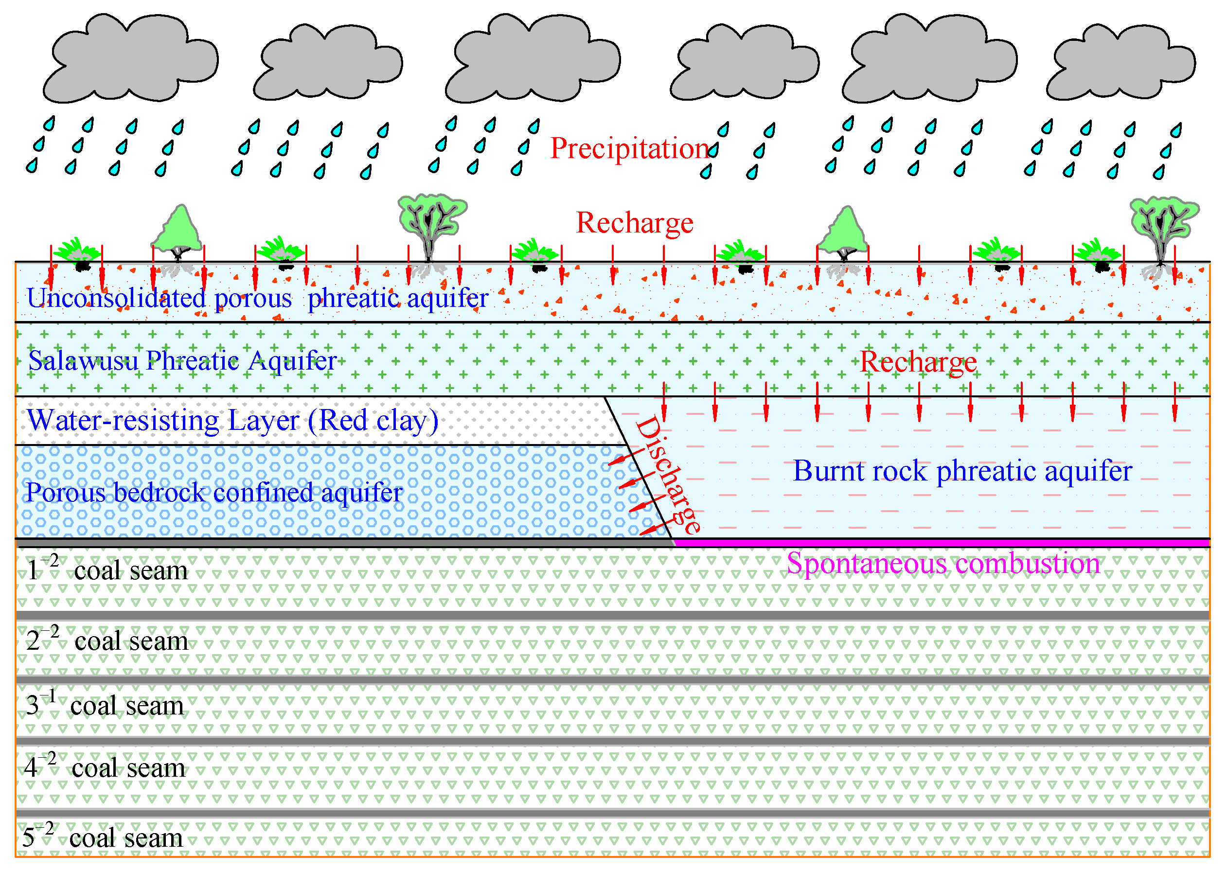
From bottom to top, there are total four types of aquifer in the Yu-Shen mining area, namely, the porous bedrock confined aquifer, burnt rock phreatic aquifer, Salawusu phreatic aquifer and unconsolidated porous phreatic aquifer, as shown in
Figure 14.
The porous bedrock confined aquifer features minor porosity, high permeability, extremely low water yield property and restricted distribution range. Additionally, the burnt rock phreatic aquifer is primarily recharged from the overlying Salawusu phreatic aquifer and itself cannot form an independent water-storing formation. By contrast, the Salawusu Formation aquifer is widely distributed in the mining area, with thickness ranging from 0 m to 67.3 m and the water table being generally less than 10 m. The unconsolidated porous phreatic aquifer in the study area is weak and mainly recharged by precipitation, usually forming a united aquifer with the underlying Salawusu formation aquifer. The united buried shallow aquifer is what we called shallow water. It is the major aquifer in this area for domestic and ecological water supply, which needs to be considered during water conservation coal mining.
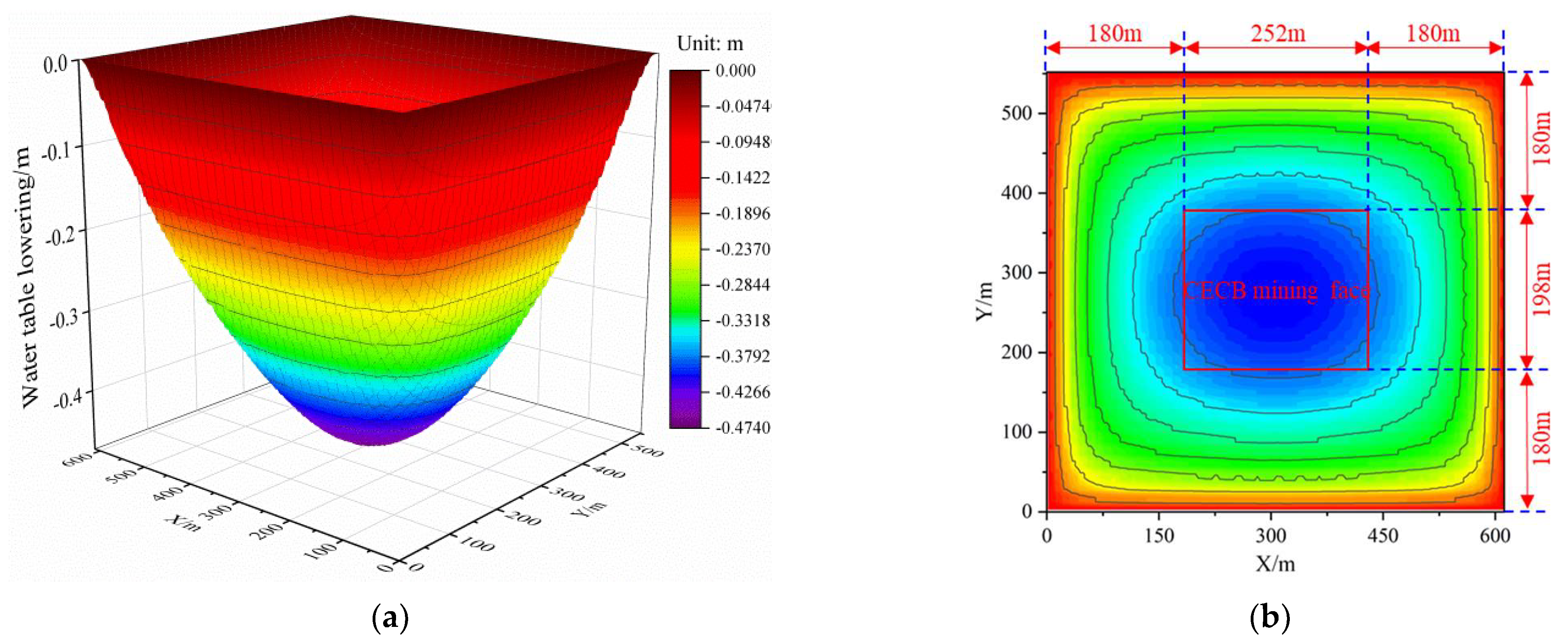
5.4.3. Numerical Simulation Results of Water Table Lowering of Shallow Water
The water level fluctuation can be investigated according to the change in pore water pressure since the shallow water is not a confined aquifer. The groundwater depression cone and the contour map of water table lowering employing the CECB water-conserving coal mining method and CMFB with 75% fly ash are shown in
Figure 15. The groundwater level has decreased by 0.47 m, indicating a narrow variation in groundwater level. In addition, the water level drop of the shallow aquifer using CMFB with different fly ash contents is shown in
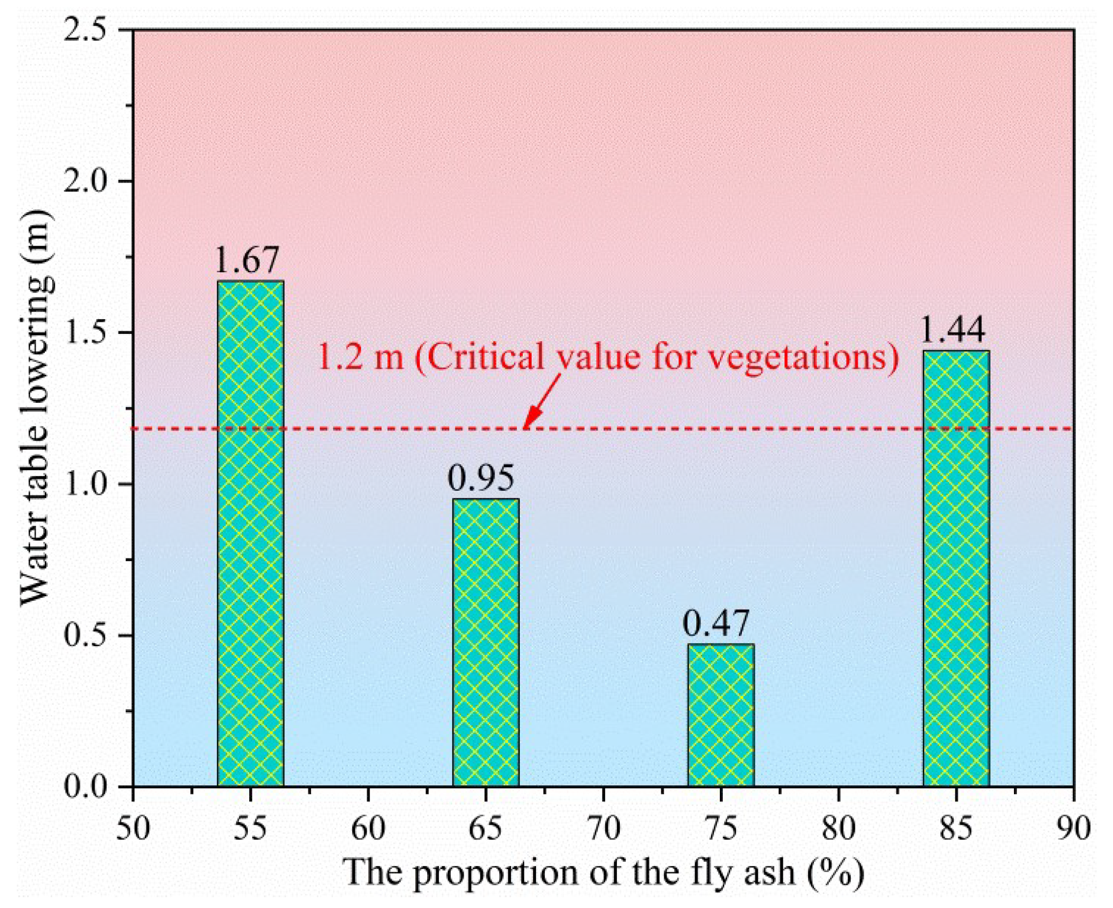
Figure 16.
The main types of vegetation in the study area are Salix psammophila, Artemisia annua, Populus euphratica and Saliz matsudana. The buried depth of shallow water ranges from 0.5 m to 1.8 m, and the surface vegetation is flourishing and exuberant. According to the field investigation of academician Wang Shuangming [
30], the relationships between the growth conditions of the aforementioned vegetation and the shallow water level are listed in
Table 6. It can be seen that when the buried depth of groundwater exceeds 3.0 m, the growth of surface vegetation will be restrained and thus degraded. Therefore, the water table drop should not be greater than the range varying from 1.2 m to 2.5 m. In order to ensure the flourishing growth of surface vegetation above the CECB mining face, the mining-induced water table lowering should be strictly less than 1.2 m.
According to
Figure 16, the decline in water level using CMFB with 55% and 85% fly ash is 1.67 and 1.44 m, respectively, neither of which meet the requirements for water conservation coal mining. By contrast, the CECB mining method using CMFB with 65% fly ash has caused a 0.95 m water table drop, 80% of the critical groundwater level drop for surface vegetation, and is therefore an alternative since it is under the threshold. It is apparent that the CMFB with 75% fly ash was the most suitable one to protect precious shallow water and surface vegetation, contributing to water and ecology preservation coal mining.
6. Discussion
This paper describes a prospective investigation on developing carbon dioxide mineralized filling body (CMFB) at ambient temperature and pressure and sequestrating it in the MRs of the CECB mining method, offering a novel way to realize CO2 sequestration. Additionally, CMFB development by using fly ash, etc. can contribute to the harmless treatment of solid wastes and prevent their pollution of air, soil and shallow water. Moreover, fly ash is cheap and can be widely obtained. Hence, selecting fly ash as aggregate in CMFB can greatly reduce the amount of cement and reduce the total filling costs. The research results are conducive to the coordinated development of coal extraction and water resource preservation, contributing to shifting the single situation of “water conservation mining” to “low-carbon collaborating solid waste treatment water conservation mining”. The paper provides a theoretical basis and reference for the field implementation of CMFB in the future and thus facilitates the construction of green and sustainable mining areas.
Traditional CO2 mineralized coal-based solid waste technology needs catalytic nucleation at high temperature and pressure to improve the reaction rate of CO2 and mineralized nodule rate, which is difficult to realize in large-scale industrialization. Therefore, it is of great scientific and engineering significance to explore and develop CO2 coal-based solid waste filling materials at ambient temperature and pressure. On the other hand, it is necessary for the CO2 mineralization process to be carried out continuously in a relatively confined space, which is coincident with the characteristics of the CECB mining method. The MR of CECB has good leak tightness during and after mining and filling, and the dimensions of the MR can be adjusted flexibly. By optimizing the layout and the dimensions of the MR, it can not only ensure the long-term mineralization of coal-based solid waste with CO2, but can also realize water preservation coal mining. However, the field application of CMFB needs to solve a series of problems, including large-scale CO2 capture, filling material transportation and the weakening of the stability of CMFB after reacting with water.
At present, water preservation mining methods are primarily harmonic mining, partial mining, curtain grouting, overburden bed separation grouting and backfill mining. Harmonic mining optimizes the working face layout, the mining sequence and the advancing direction uniformly to counteract the movement of overlying strata. However, its popularity and applicability are limited due to the various distributions of protected objects (overlying aquifers, buildings and structures). In addition, the partial mining left coal pillar unmined permanently or abandon a portion of coal resources to support the roof and thus realize the mitigation of overburden deformation and thus shallow water loss. Hence, large amounts of resources are wasted and there is a low recovery rate of generally less than 50%. Additionally, curtain grouting injects the slurry into the cracks, pores or mining-induced fractures between the overlying shallow water and the mined-out area. The purpose of the method is to form a continuous curtain that can block the water percolation channel from the overlying aquifer to the gob. However, it suffers from limited adaptability and curtain instability after grouting in the long term. The overburden separation grouting fills the stratum separation space by drilling grouting, so as to mitigate the overburden subsidence and thus preserve the shallow aquifer. It can only be applied in the bed separation space where the lithology of the upper stratum is harder than that of the lower and the effects of reducing overburden subsidence are restricted. Backfill mining is currently the most effective method to control overlying layer migration and thus conserve the shallow water since it substitutes the coal body with the filling body to support the roof of the mined-out area, which can significantly lighten the overlying layer migration and shallow water loss [
6].
Backfill mining is primarily longwall backfill mining and shortwall backfill mining. The former has the problems of insufficient filling time and filling space. The roof of the mined-out area subsides and collapses immediately after the coal seam is extracted. However, it takes a long time for the backfill to reach its designed strength, and the goaf roof cannot be supported in time. Therefore, the movement of the overlying strata is inevitable, giving rise to difficulty in safe and high-efficient coal extraction under shallow water. Moreover, since the mining and filling exist in the same space and are not separated completely in longwall backfill mining, the filling speed affects extraction progress, while equipment maintenance delays the filling process, contributing to the mutual influence and restriction between extraction and backfill. It is arduous for them to operate in parallel. By contrast, the CECB mining method sets the coal extraction roadway and the backfill roadway in two different positions, with a large distance between them. Skip and interval mining offer a separated space for extraction and backfill which ensures isolated filling and mining processes and can realize mining and filling simultaneously without mutual restrictions and effects. Additionally, the width of the roadway is narrow compared with that of longwall backfill mining which can reduce the immediate roof subsistence effectively [
7].
The CECB method has the advantages of integrating extraction and excavation, parallel mining and filling operation, convenient moving of the working face, low investment and high recovery rate over other mining methods. Compared with traditional longwall backfill mining, the CECB method arranges the coal extraction system and backfill system in different positions, avoiding the interaction between mining and filling operation, and thus the working efficiency can be ensured. The exposed area of each MR is small and results in limited subsidence of the roof before backfill, which is beneficial to the primary stability of CMFB before reaching the designed strength. Therefore, CMFB is an ideal backfill material for CECB. However, the feasibility of other backfill mining methods, such as longwall backfill mining, needs further study, due to the fact that their mining processes are essentially different from that of CECB mining. For example, the mining space of longwall backfill mining is not completely separated from the filling space. It seems that injecting the CMFB into the flexible bags set ahead in the filling space is the only option, which may lead to CMFB instability since it cannot be sealed due to the rupture of the flexible materials.
The authors developed high water swelling filling material with fly ash as aggregate and lime, anhydrite, cement and additives as ingredients [
8]. The viscosity, bleeding rate, expansion rate, uniaxial compressive strength, slump, initial setting and final setting time of specimens with different water–solid ratios were studied. With due consideration given to the specific engineering and geological conditions of the colliery, the reasonable water–solid ratio and the material ratio of filling materials were determined. In the XV2309 working face of Wangtaipu Coal Mine in Shanxi Province, an industrial test was carried out with the developed filling material [
39]. The strength of the filling body is 5 MPa with 60 days’ setting time, the average expansion rate is 7.63% and the average bleeding rate is only 0.1%. The deformation of the water-resisting layer is mitigated and water table lowering of the overlying aquifer is effectively controlled and reduced. The filling cost per ton of coal when all MRs are backfilled is CNY 120, which is slightly higher than CNY 100 for longwall backfill mining. In addition, the maximum daily and annual output of CECB exceeds 3000 t and 600,000 t, respectively, almost the same as that of longwall backfill mining. The previous research on the CECB mining method and the development and field application of high water expansion filling materials laid a solid foundation for further study on the field implementation of CMFB in future.
In general, the CECB water preservation mining method meets the strategic requirements of the coordinated development of coal resources and the ecological environment. It has been popularized and applied to Yuxing Colliery, Wangtaipu Colliery, Suncun Colliery, etc. in northwest China, since it can make full harmless use of solid wastes accumulated around the mining areas on the premise of safe and highly efficient coal extraction with a high recovery rate. The practice results show that good economic, social and environmental benefits have been achieved in the aforementioned collieries. According to statistics, as of the end of 2020, a total of 2.60 million tons of coal resources have been recovered by CECB in dozens of coal mines and a total new profit of more than 40 million dollars has been achieved [
11]. However, all the previous field implementations of CECB used cement paste filling materials, crushed gangue or high water content filling materials. At present, the field application of CO
2 gas adhering to the filling materials to realize CO
2 sequestration has not been reported. In following research, a scanning electron microscope, X-ray diffraction, Vicat instrument, etc. will be employed to analyze the mesostructure, setting time and the rheological properties of the CMFB, and further exploration of the mechanism of the reaction among CO
2 gas, solid wastes and additives will be carried out, so as to provide a valuable theoretical research basis for the field implementations of CMFB in the future.
In view of the hydrogeological conditions where the distance between the overlying aquifer and the coal seam is large and the aquiclude between them is thick, the material ratios of filling materials can be adjusted to cut down the filling cost on the premise of mitigating the overburden migration and thus preserving water resources. For example, in the industrial test of Wangtaipu Coal Mine, we adjusted the water–solid ratio of the filling body in the last mining phase from 0.8:1 to 0.9:1 since the water level is controlled successfully in the early mining phase. In addition, further study on the deformation of the aquiclude and the fluctuation of the water level under the conditions of partial backfill of MRs in CECB will be conducted. If the shallow water preservation coal mining can be realized without filling in the last one or two mining phases, a further reduction in filling cost will become reality.
7. Conclusions
The conclusions drawn from the research are as follows:
(1) The scientific concept of developing CMFB by making CO2 react with coal-based solid waste such as fly ash at a normal temperature and pressure and injecting it into the confined MR of the CECB mining method, was proposed. It can contribute to constructing the “trinity” of green and low-carbon mining areas, with permanent CO2 storage, harmless treatment of coal-based solid wastes and shallow water preservation.
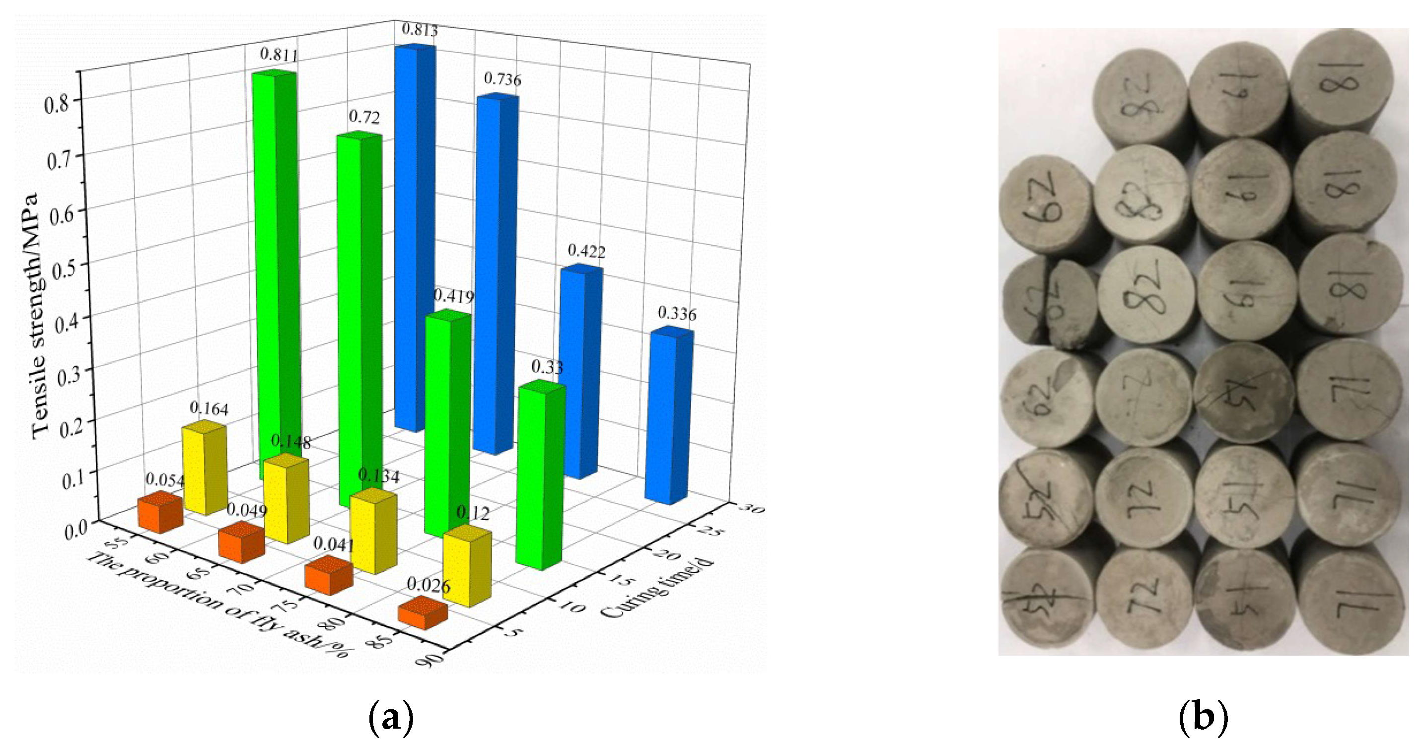
(2) The CMFB was developed at ambient temperature and pressure by using fly ash as aggregate, and CO2 gas, silicate additives and cement as accessories. The UCS and tensile strength of CMFB with various curing times (3 d, 7 d, 14 d, 28 d) and different fly ash contents (55%, 65%, 75%, 85%) were tested indoors. The test results show that the compressive and tensile strength of CMFB increases with longer setting time. With the rising fly ash proportion, the compressive strength of CMFB increases first and then decreases, reaching the maximum when the fly ash content is 75%, while the tensile strength diminishes continuously.
(3) The commonly and extensively utilized filling materials are primarily cemented filling materials, crushed gangue and high water content filling materials. When the backfill mining method was previously employed to extract coal bodies beneath the overlying aquifer on the premise of water preservation and conservation, measures were usually adjusted to local conditions and the filling bodies were developed by taking materials from a wide range of sources as the raw materials. For instance, in view of the typical geological feature of aeolian sand, widely distributed in the Yu-Shen mining area, Shaanxi province, northwest China, Liu Pengliang et al. developed a new aeolian sand paste-like material with aeolian sand being used as aggregate and alkali-activated fly ash being utilized as a cementing agent. It was then applied to the Yuyang Colliery and the problem of damage to Salawusu Formation Aquifer caused by longwall caving mining was tackled [
53]. Additionally, in view of the collieries without sufficient and abundant gangue accumulation, Zhou Nan et al. developed a sand-based cemented paste filling material with widely distributed and low-cost Yellow River sand as filling aggregate and cement and fly ash as binder for Zhaoguan Colliery in Shandong Province of China, which is only 5 km away from the Yellow River [
48]. Zhou Huaqiang et al. used the developed paste filling materials to extract a large number of coal resources under the village [
54]. Feng Guangming developed ultra-high water filling material and put forward the corresponding mining technology [
55]. However, the above mining methods and filling materials only take the harmless treatment of solid wastes and the overlying aquifer preservation into account, without regarding CO
2 sequestration as one of the purposes of backfill mining. This paper brings the large-scale treatment of CO
2 into the scientific framework of colliery green mining, and puts forward the trinity concept of green mining for CO
2 sequestration, harmless treatment of solid wastes and shallow water table preservation, which is innovative compared with the previous research on water conservation coal mining. The research results can provide theoretical guidance for the development and field application of CMFB, and promote construction of green, low-carbon and sustainable coal areas.
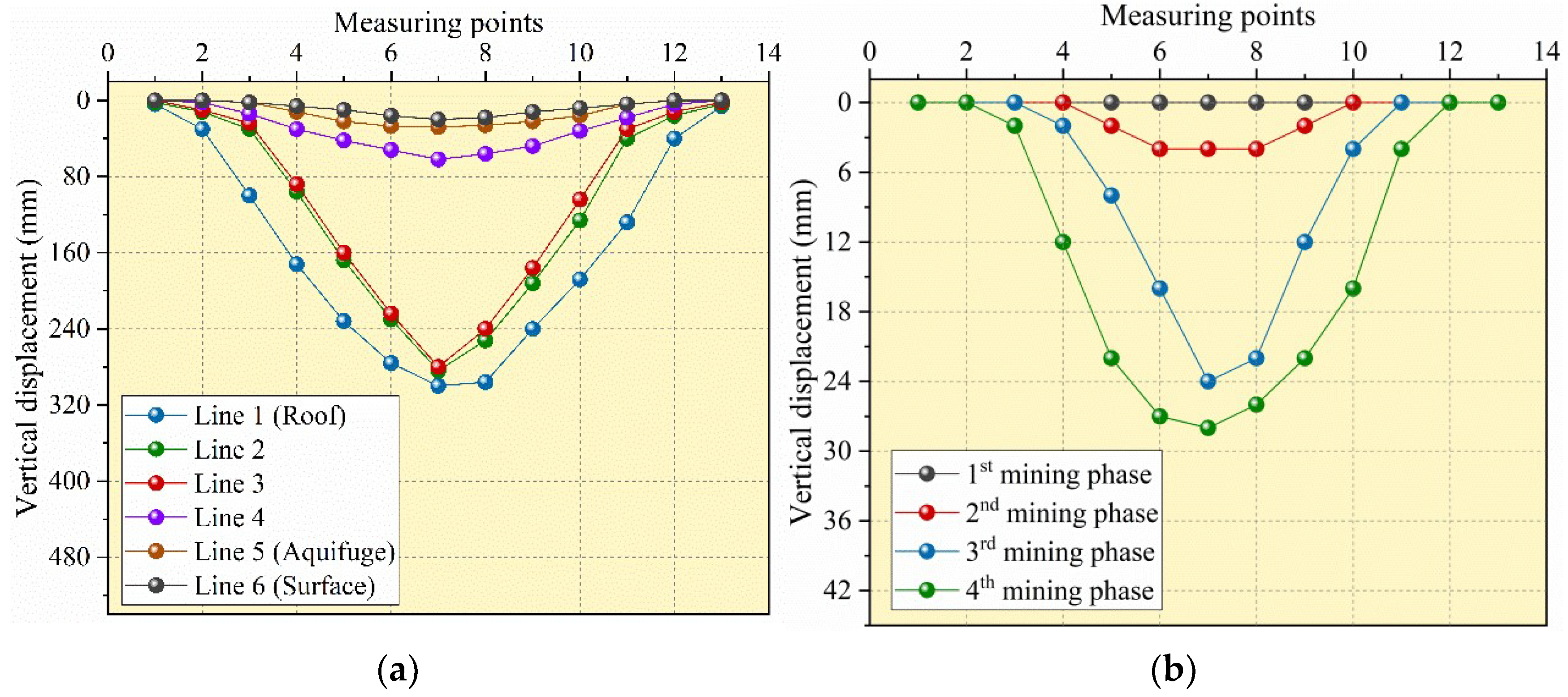
(4) According to the stress–strain curve of the CMFB from the indoor UCS test, the material ratio of the similar material of CMFB was optimized and determined. The physical analogue model was then constructed to simulate the mining-induced deformation of the overburden and aquifuge while using the CECB mining. The subsidence of the aquiclude from physical analogue simulation shows good agreement with that from the numerical simulation. The maximum vertical displacement of the water-resisting layer is 28 m, only 7.7% higher than that of the numerical simulation.
(5) The FLAC3D finite element software was employed to simulate the aquifuge deformation and water table lowering. The CMFB with 14 d curing time and various fly ash contents were taken for analysis. Based on the indoor test results and the numerical simulation results, the strain-softening parameters of CMFB in the numerical simulation model were calibrated systematically. The deformation of the water-resisting layer and the decline in the water level of the shallow water while injecting CMFB with different fly ash contents into the MRs of CECB were obtained. The CMFB with 75% fly ash can effectively protect the integrity and water-blocking stability of the overlying aquiclude and mitigate the water level drop of the underground aquifer, thus preserving the shallow water and surface vegetation and contribute to the construction of green and sustainable ecological mines.


