Article

Upgrading the Power Capacity of a Three-Conductor MVAC Line by Converting to DC

by
Aleksey I. Bardanov
1,*,
Sergei V. Solovev
1,
Ricardo Alvarez
2,
Juan M. Munoz-Guijosa
3,
Miguel Jiménez Jiménez Carrizosa
4 and
Andrés Mora
2
1
Department of General Electrical Engineering, Saint Petersburg Mining University, 199406 Saint Petersburg, Russia
2
Department of Electrical Engineering, Universidad Técnica Federico Santa María, Avda. Vicuña Mackenna, San Joaquín, Santiago 3939, Chile
3
Mechanical Engineering Department, Universidad Politécnica de Madrid, C/José Gutiérrez Abascal, 2, 28006 Madrid, Spain
4
Centro de Electrónica Industrial, Universidad Politécnica de Madrid, C/José Gutiérrez Abascal, 2, 28006 Madrid, Spain
*
Author to whom correspondence should be addressed.
Energies 2022, 15(3), 1080; https://doi.org/10.3390/en15031080
Submission received: 1 December 2021 / Revised: 24 January 2022 / Accepted: 26 January 2022 / Published: 1 February 2022

Abstract

:
Several countries around the world are undergoing a radical transformation of their electricity networks, with the widespread integration of distributed generation based on renewable energy sources at the center of the change. Under these scenarios, DC links are becoming an attractive option for the infrastructure of modern networks, especially at medium voltage levels. This work is devoted to the integration of DC systems in existing AC networks by converting AC power lines to DC. The work presents a novel method for converting a three-conductor medium voltage AC transmission line to DC. The efficiency of the proposed conversion is assessed in terms of increased power capacity. It is shown that the proposed approach allows for increasing the power capacity of the line by at least 10%. The feasibility and effectiveness of the proposed method are then confirmed by laboratory experiments.

1. Introduction

Recent reports provided by international agencies on power systems show the need for power system transformations [1,2,3,4]. Forecasts predict a transition from centralized power supply systems to adaptive ones based on distributed energy resources (DER). The idea of an Internet of Energy (IoE) [5] assumes widespread integration of Information Technology (IT) in the field of energy [6,7] and supports the trend toward a transition to flexible systems.
In AC grids, maintaining high efficiency and stability, allowing the integration of DER and bulk energy storage, obtaining optimal power flow, and ensuring power quality altogether is challenging. Hence, the IEEE forecast for 2050 [4] assumes that power systems of the future will combine the advantages of variable frequency AC and DC. Several works have shown that a combination of AC and DC in power systems may bring significant benefits at both transmission and distribution levels [8,9,10,11,12,13]. The advantages of hybrid AC/DC grids include better power flow and nodes voltage control as well as reduced power and voltage losses.
Since the last century, DC has been used within AC networks for long distance bulk power transmission [14,15] and in residential networks [16,17,18,19]. However, for a long time, medium voltage DC (MVDC) systems were impractical due to the high cost of power conversion. Given the advances in the field of power electronics [20,21], the implementation of MVDC power lines into transmission and distribution systems is becoming an attractive option. The ABB report on MVDC technology [22] highlights a number of promising areas of applications of MVDC in modern electrical grids including:
  • The ability to connect substations at the same voltage level for direct power exchange;
  • Increasing the power capacity of transmission lines;
  • Connection of power-intensive loads in urban environments;
  • Connection of remote consumers including microgrids;
  • Connection of renewable energy sources and storage units;
  • Transmission of electricity by submarine cable lines at medium voltage levels.
When trying to integrate DC lines into an existing AC power system, a dilemma arises: whether to build new DC lines or convert existing AC lines to DC. Depending on the context, both options are justifiable. However, a significant advantage of AC to DC conversion is that it can be performed with minimum structural modifications, thus allowing for a fast and socio-environmentally friendly increase of the capacity of the line [23,24,25]. In addition, building new lines may not be possible in some cases due to space limitations.
Early works on this topic were focused on AC to DC conversion of high voltage power lines [26,27]. In these works the authors proposed reconstructing power lines by replacing tower heads and insulators. Since no change is made to the conductors, the gain in power capacity depends mostly on the voltage uprate. As for the design, two options for converting a three-phase AC line to a DC one were suggested. The first option is to convert the AC line to a monopolar DC system with ground return. This can be achieved by connecting all three conductors to the same pole while the current returns through the ground. The second option is to convert it to a bipolar DC system with neutral conductor. In this case, two of the conductors are connected to the positive and the negative pole, respectively, while the third one remains neutral. On the one hand, using a monopolar system with ground return allows for increasing power capacity rate up to 3.5 times [26], but it may be undesirable or even unfeasible to implement in inhabited areas due to stray currents. On the other hand, in a bipolar DC system with a neutral conductor, only two of the conductors are used to carry current, which reduces the power capacity of the line. A recent case of successful AC to DC conversion using a bipolar DC system is the UltraNet project [28] for two 380 kV AC and two 110 kV AC systems between Osterath and Philippsburg in Germany (340 km long). In this project one of the 380 kV AC systems was converted to DC. The conversion only required replacing the insulators and facilitated the power transmission of approximately 2000 MW from wind farms in the North Sea to industrial areas in southern Germany.
An alternative to bipolar systems is tripole systems [29]. In a tripole scheme, two of the conductors are connected to the positive and negative poles using unidirectional thyristor converters. The third conductor is constantly switching between the positive and negative poles using bidirectional thyristor converters. The currents of the first two conductors do not change direction, but change amperage. In contrast, the current of the third conductor (neutral wire) has constant amperage but periodically changes direction. In a tripole system, it is possible to increase the power transfer capability 37% by overloading the main conductors periodically for short periods without exceeding their thermal limit and by also using the neutral conductor to carry current. Further improvements of this method have been carried out to implement transistor-based converters [30] and to optimize the switching scheme [31]. Despite its benefits, the tripole scheme has not been widely used [32].
The same approaches were used for MVAC to MVDC conversion. For example, the 35 kV AC submarine cable line for supplying power to the offshore platform of the Wenchang oilfield group in China was converted in 2011 to a ±10 kV bipolar DC line to maintain a 3 MW capacity [25]. Another example is the Angle-DC project in the UK [33], where a 33 kV MVAC line across the strait between the island of Anglesey and North Wales was converted to a ±27 kV bipolar DC line. In [8] the efficiency of converting AC lines to DC for increasing the power capacity in urban medium voltage power lines was investigated. The efficiency of the conversion was evaluated in terms of rating power capacity, voltage drops, and power losses. The authors proposed a symmetrical configuration with a neutral wire for three-conductor lines and two types of DC systems for four-conductor lines: a symmetrical configuration without a neutral wire and an asymmetrical configuration with a neutral wire. Since the conversion was designed for urban networks, no ground return was considered. As a result, the authors determined that four-conductor lines were the most efficient alternative. Also, a conversion without voltage uprate is almost ineffective for three-conductor lines (especially for cables).
In the aforementioned context, this article extends the work in [34] and presents a novel approach for AC to DC conversion in lines with three-conductors at medium voltage levels and demonstrates its feasibility and effectiveness. With the proposed approach, the thermal capacity of all conductors is utilized, thus allowing an increase in the power transfer of the line. Furthermore, the article proposes an original criterion to evaluate the efficiency of the conversion that considers the voltage drop and the conductors’ thermal limit in a wide range of load and line parameters. The feasibility of the proposed approach and its efficiency are supported by experimental results. The technical and economic benefits of AC to DC conversion are out of the scope of this paper and will be addressed in future works. The proposed approach has many applications. It can be used as part of a major AC to DC conversion strategy, which may be the objective in some jurisdictions, or as an alternative for increasing the transmission capacity in urban areas and/or areas of high population density where adding a parallel line is not an option.
The remainder of this article is organized as follows: Section 2 presents the proposed method to convert a medium voltage three-conductor AC power line to DC. Section 3 presents the experimental setup and the results. Finally, Section 4 presents a discussion and the conclusions.

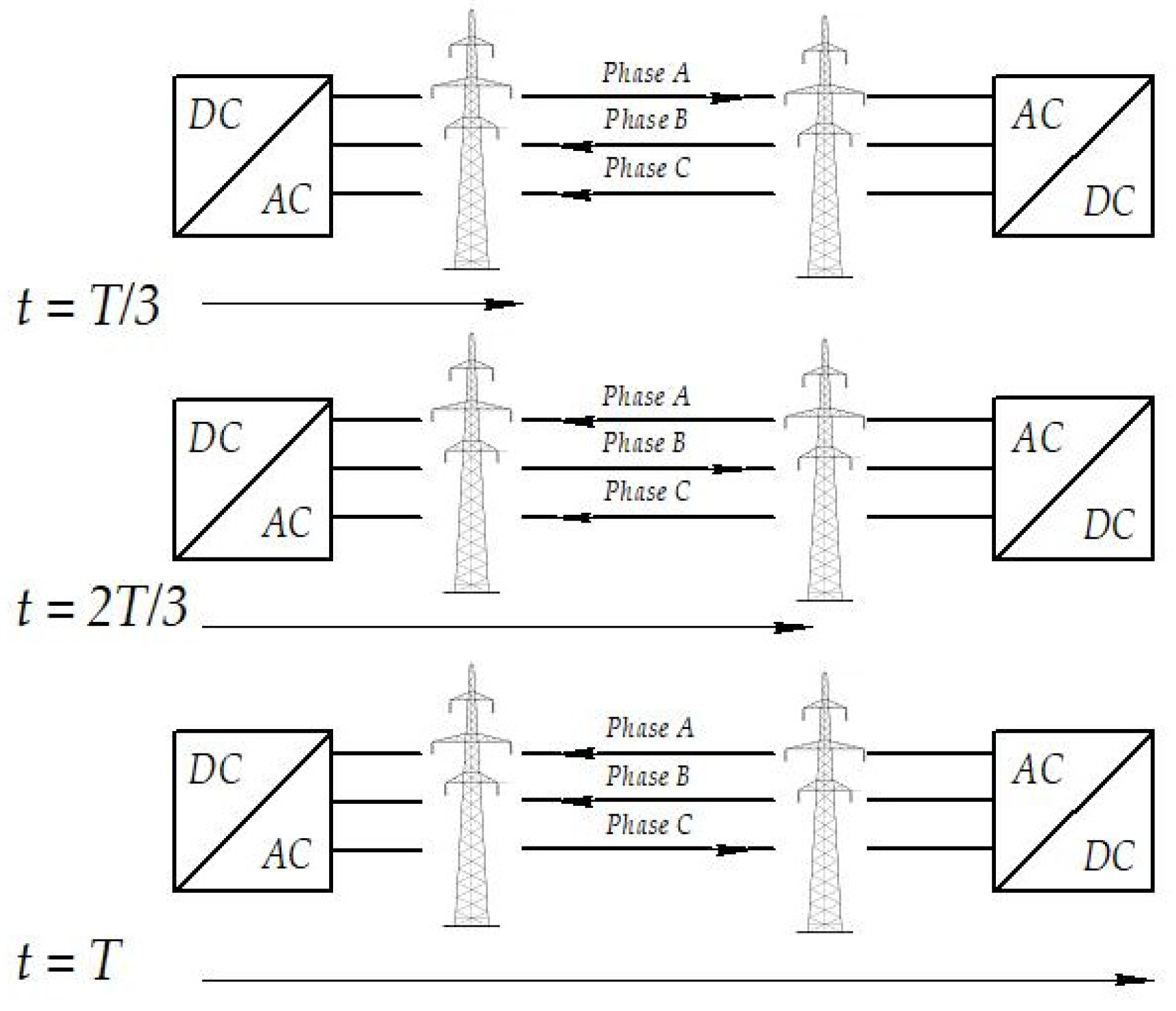
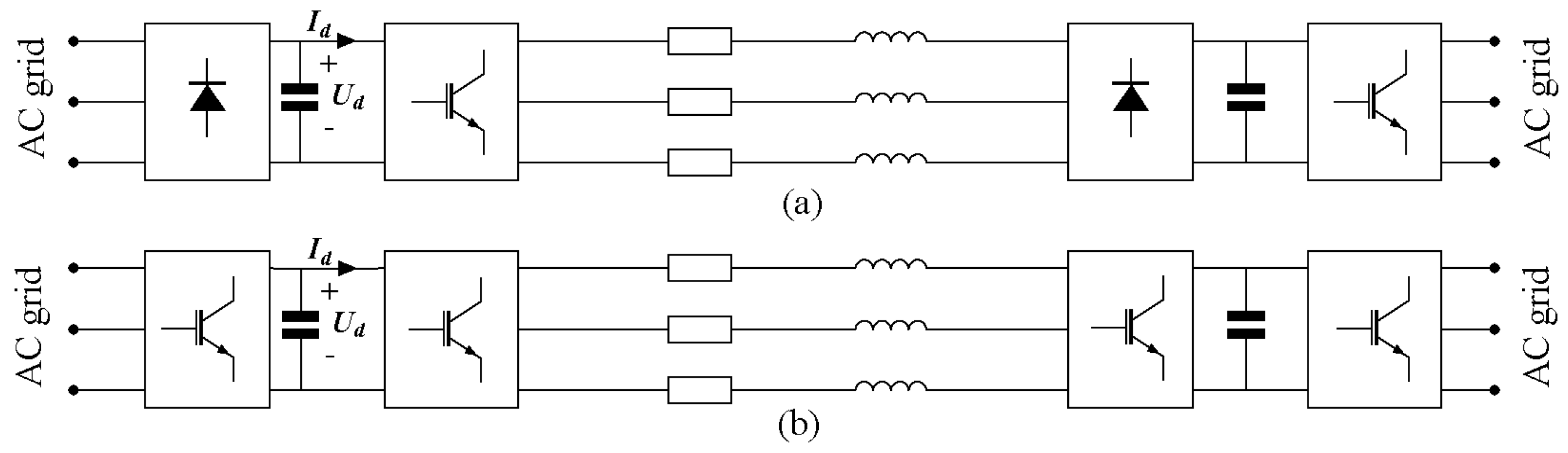
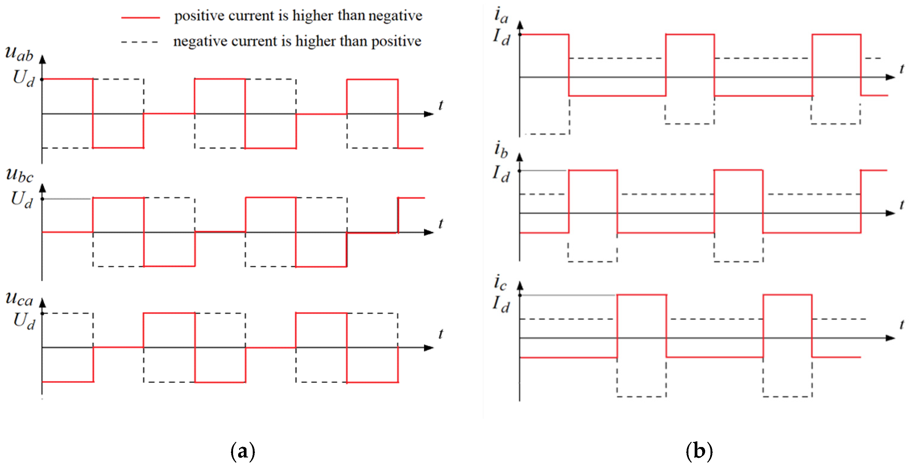
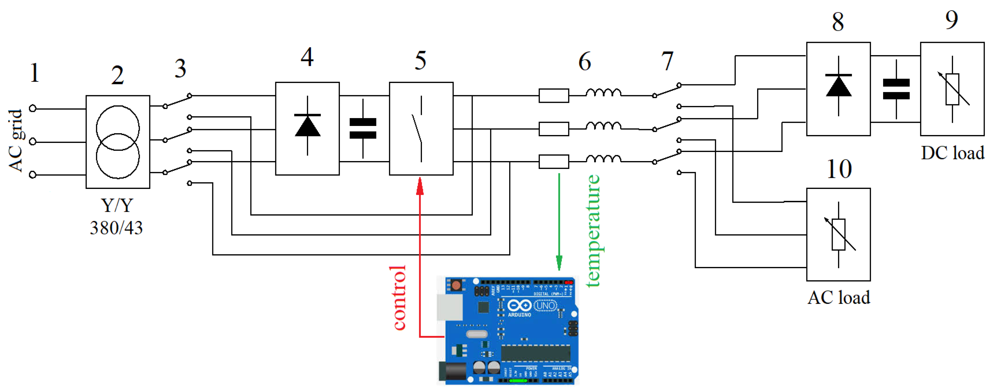
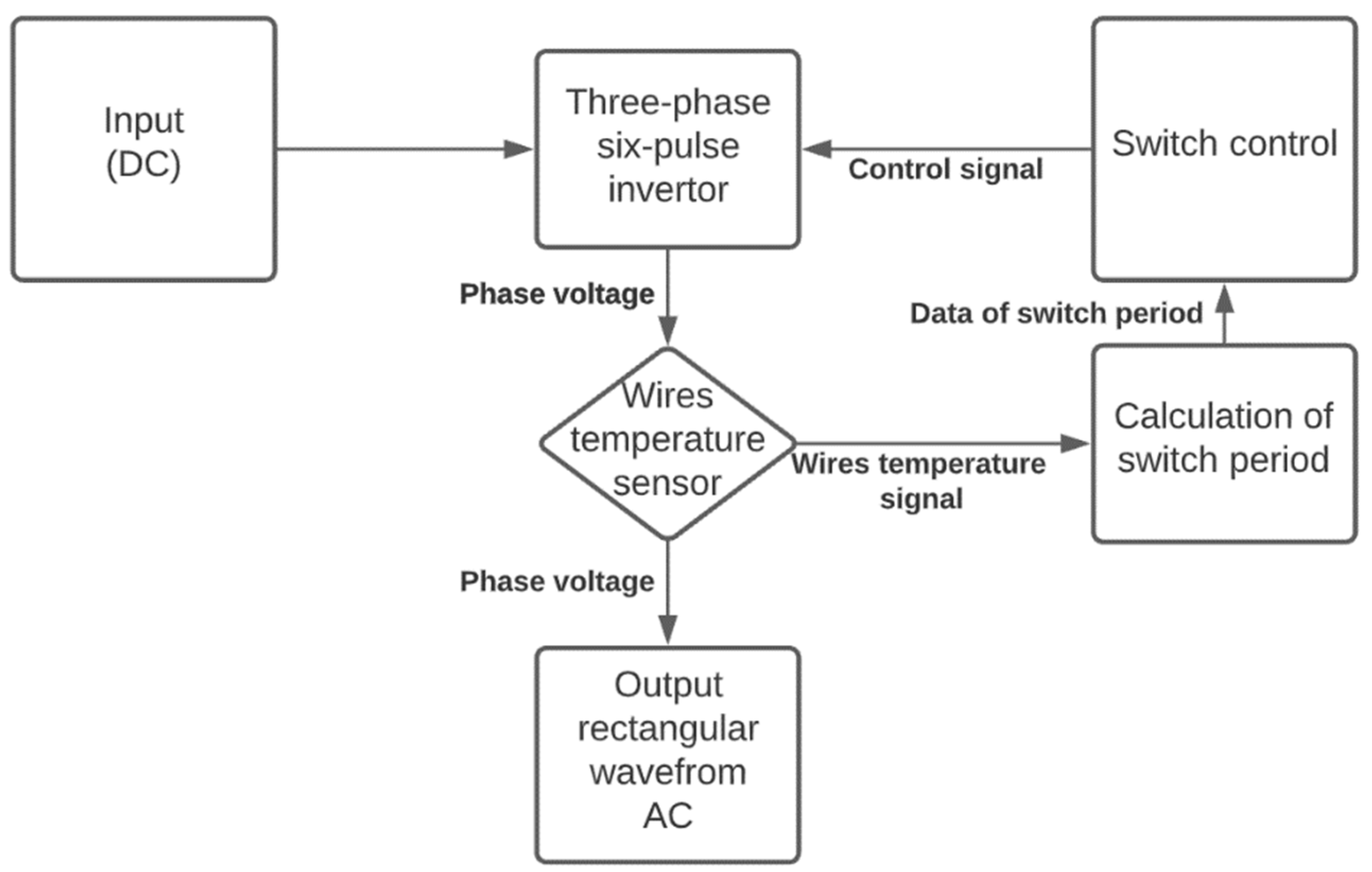
2. Proposed Method for AC to DC Conversion

When transmitting electricity from a DC voltage source using three-conductor lines, if one of the conductors is connected to the positive pole, while the others are connected to the negative pole, the full current will only pass through the first conductor. The other two conductors will carry only half of the current, and the thermal margin of these conductors will not be fully utilized. One possibility to achieve better usage of all three conductors is to switch between fully and half-loaded conductors periodically, as shown in Figure 1. In this work, we define the time during which each of the three conductors will carry full amperage as switching period T .
To implement this approach, full-bridge six-pulse diode rectifiers and full-bridge inverters based on IGBTs can be adopted, as shown in Figure 2. The main target of the proposal is to show how the wires are switched. In this regard, the topology can also be upgraded by using solid-state transformers (e.g., [35,36]). The range of voltages and currents for which this technology is designed to be used is estimated as 10–20 kV and 100 A. Note that full-bridge inverters have also been successfully used to control current flows for different purposes (e.g., [37,38]).
For the analysis we have neglected the inner rectifiers’ voltage losses and assume that the rectified DC voltage Ud is:
U d = 3 6 · U π ,
where U is the RMS value of the alternating line to ground voltage.
Equation (1) is related to a six-pulse full-bridge diode rectifier with constant DC current (a large inductance is assumed at the dc-side). Since the rectifier DC link contains a capacitance, the actual DC voltage value will be different. However, Equation (1) can be used to estimate it. Figure 3 shows the expected voltage and current profile for a given switching frequency.
From Figure 3 it can be seen that the conductor carrying the full current will heat quicker than the others, but only during one-third of the period. During the remaining time, the conductor cools down. For illustrative purposes, Figure 4 shows the temperature of the conductor in steady state including both constant and transient components. The average conductor temperature ( T a v r ) depends on the current amperage ( I d ) , while the switching period ( T ) affects the amplitude of the fluctuations. Note that higher switching frequencies lead to smaller deviations from the average temperature. This constant switching of the conductors allows increasing the current I d that can be transmitted without exceeding the maximum temperature of the conductors. Regarding the choice of the switching period, note that the heating time constant of the wires is 5–10 min, which is several times higher than the switching periods in classic power electronic devices. Therefore, when designing a wire switching device for the proposed power transmission method, it is possible to choose a wire switching period of less than a minute and expect low wire temperature ripples (less than ±5%). For the experiment, we chose a wire switching period of 15 s.
The RMS value of the current I d that can be transmitted with the proposed methodology, compared to the current I that can be transmitted with an AC transmission line can be estimated as follows:
I 2 = 1 3 I d 2 + 2 3 ( I d 2 ) 2 = I d 2 2
Hence, the proposed methodology allows increasing the RMS value of the transmitted current by a factor of 2 :
I d = 2 I
In summary, the proposed approach for AC to DC conversion allows the use of the temperature margin of all three conductors. Moreover, since all three conductors are valid for power transfer in case of a single conductor failure, it is possible to maintain the transmission capability using the remaining two wires at reduced power. Additionally, there is no space static charge around the wires due to the constant polarity change of AC systems [39]. Note that for power system design, the line loadability is usually determined for worst-case ambient conditions (for example, 35 °C and wind velocity of 0.3 m/s). Hence, the benefits of the increased line loadability with the proposed method, can also be captured within power system design.

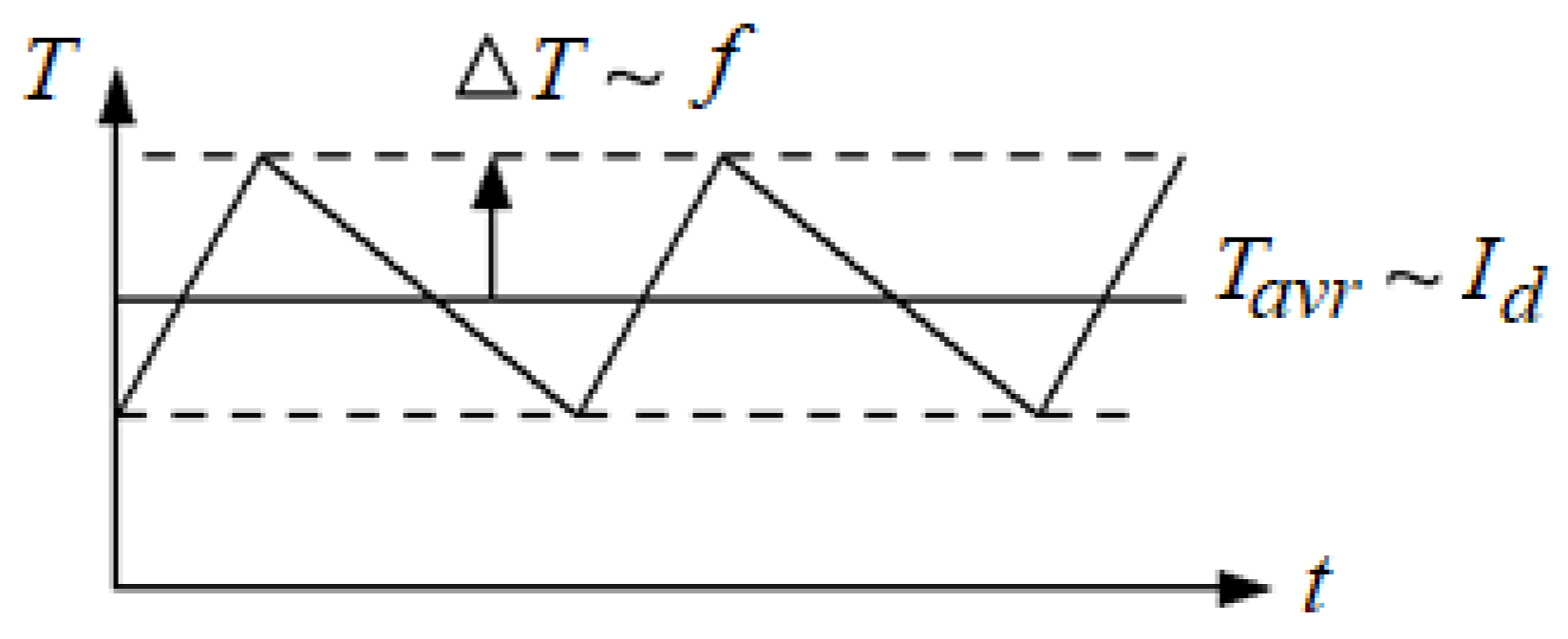
2.1. Analysis of the Increased Power Capacity of the Line Using the Proposed Method

Comparing the performance of different conversion techniques is usually undertaken in the context of power capacity upgrades [40]. Power capacity is estimated for current (relevant for short lines, typically below 80 km), voltage (for lines between 80 km and 320 km) and stability (for lines longer than 320 km). Since the method is proposed for medium voltage power lines, the stability criteria were not considered. Voltage and current restrictions were adopted for comparison purposes. It is also assumed that switchgears do not restrict the line’s capacity.

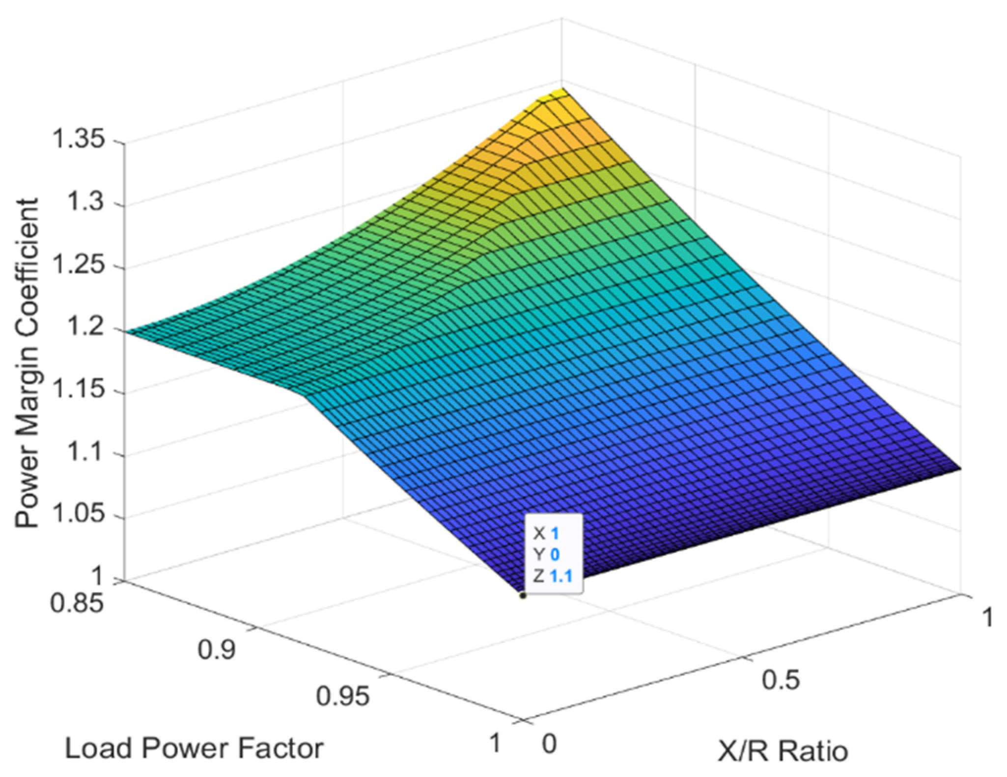
2.1.1. Power Margin Coefficient

To compare different conversion methods, we propose using a power margin coefficient. More details on this method can be found in [34]. Here, only a brief introduction of this analysis method is presented. The power capacity of a medium voltage transmission line depends on the current and the voltage. In real-world power systems, the voltage level at any point must comply with the corresponding power quality standards. To consider voltage losses in the line, a voltage margin coefficient ( K V M ) is proposed, which is defined as the ratio of the power capacity of the line converted to DC ( P D C ( U ) ) and the power capacity of a three-wired AC line considering voltage restrictions ( P A C ( U ) ) i.e.,
K V M = P D C ( U ) P A C ( U ) ,
The maximum current that can be transmitted over a power line depends on the permissible temperature of a particular conductor. To consider the increase in the power line current for the AC to DC conversion, we propose using the current margin coefficient ( K C M ), defined as follows:
K C M = P D C ( I ) P A C ( I ) ,
where P D C ( I ) is the power capacity of the DC line and P A C ( I ) is the power capacity of the three-wired AC line. Given that both criteria are important, we propose a power margin coefficient that combines them as follows:
K P M = [ K V M , K C M ]  
For short power lines, the current margin coefficient is more important than the voltage one and vice versa for long power lines. However, within our proposal, both the line voltage and the line current are considered for comparison. Note that for long distance power lines (e.g., for extra-high voltage), the stability criterion can also be included in the proposed formulation.

2.1.2. Evaluation of the Efficiency of the Proposed Method Using the Power Margin Coefficient

A few assumptions are made for the analysis. The first assumption is that the current and the voltage have sinusoidal form and that the loading of the conductors is balanced. Second, given that the frequency is 50 or 60 Hz, the difference between AC and DC resistances is negligible [41]. Third, it is assumed that the conductors of the power line are at a sufficiently large distance from each other, so that both inductive and capacitive interference are also negligible.
The basis of the analysis is plotting the power margin coefficient surface for different loads and line parameters. The plot on Figure 5 shows how the line capacity increases depending on the load power factor and the reactance/resistance ratio. Let us first evaluate the power capacity of an AC line considering the load power factor (PF) (for linear load, P F = c o s ( φ l o a d ) ):
P A C ( I ) = 3 U I c o s   ( φ l o a d )  
On the other hand, the power delivered by a DC voltage source considering Equations (1) and (3) is:
P D C ( I ) = U d I d = 3 6 · U π · 2 I .
Now, using Equation (5) it is possible to obtain K C M as follows:
K C M = U 3 6 π 2 I 3 U I c o s   ( φ l o a d )   = 1.1 c o s   ( φ l o a d )   1 .
According to Equation (9) the power capacity could be raised by 10% in the case of a unit power factor of the AC load. To obtain the voltage margin coefficient, let us assume that the conductors’ resistances ( R ) are the same. The AC power capacity considering voltage restrictions is:
P A C ( U ) = 2.7 U 2 0.81 c o s   ( φ l i n e )   2 + 0.4 0.9 c o s   ( φ l i n e )   R 1 + t a n   ( φ l i n e )     ,
where φ l i n e = a r c t a n ( X / R ) . As two conductors are connected in parallel, the full resistance of the DC line decreases by one-fourth:
P D C ( U ) = 9 · 6 π 2 U 2 1.1 · 0.9 0.9 2 R + 0.5 R .
Coefficients in Equations (10) and (11) correspond to the common power quality standards [42,43], according to which the line voltage must remain between 90% and 110% of the nominal value. Using Equations (10) and (11), the voltage margin coefficient dependent on the line’s X/R ratio are as follows:
K V M = 0.24 1 + t a n   ( φ l i n e )     0.81 c o s   ( φ l i n e )   2 + 0.4 0.9 c o s   ( φ l i n e )   .
According to Equation (12) if X/R = 0, then the power capacity of the line could be increased by at least 20%. To consider both voltage and current restrictions, in Figure 5 we plot the power margin coefficient surface using Equation (5). This figure demonstrates that the proposed conversion approach achieves an increase of at least 10% of the line’s power capacity. From this figure it can be seen that the lower the PF of the load, the higher the conversion efficiency. For relatively low PF loads, the power capacity is restricted by the voltage drop of the line. However, even in cases of purely resistive lines, which is very unlikely, the minimum possible power capacity upgrade is 20%.

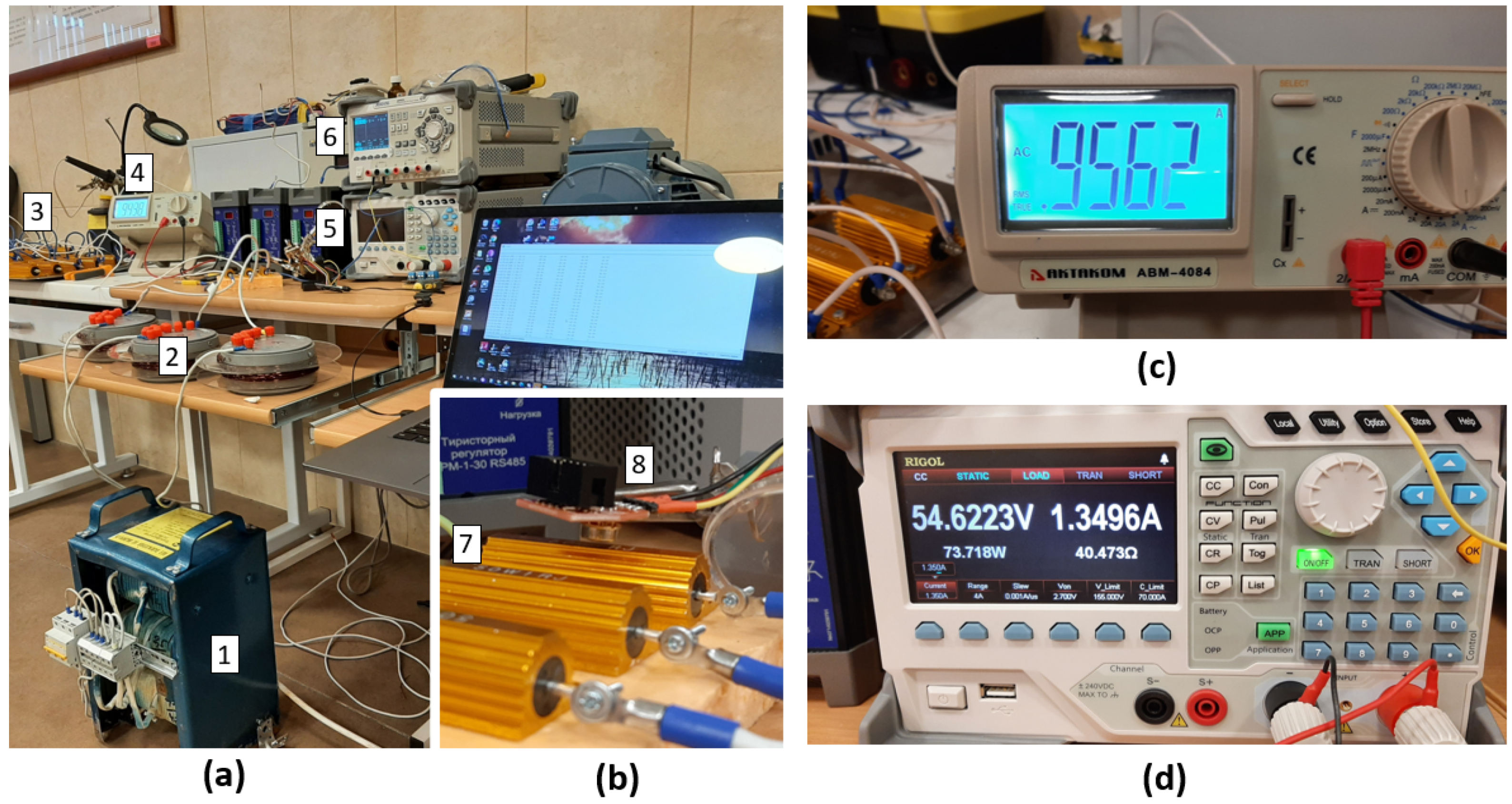
3. Experimental Validation and Results

The proposed method was validated experimentally in laboratory conditions. The experimental bench was created for a relatively short power line; thus, it was possible to neglect the line capacitance. The line was modeled with a reactance of 1 Ohm in series with an inductor of 3 mH. For a medium voltage line of 35 kV, this would approximately correspond to a 10 km line. The scheme of the bench is shown in Figure 6. Note that this assumption does not hold for long power lines, and therefore in those cases telegraph equations have to be considered. Since the power capacity margin coefficient is irrelevant for transient analysis, only steady-state operating conditions were investigated. As part of the experiment, the temperature of the wires was measured during the transmission of electricity with three-phase AC and with three-conductor DC. The voltage drop across the load was also measured when the conductors were switched.
As depicted in Figure 6, the laboratory test bench was powered by a three-phase 230 V 50 Hz voltage source. The 380/43 V transformer (25 V per phase) reduces the voltage to a safe level on the input side. Depending on the position of the bypass switch, the voltage was supplied either directly to the power line or to a full-bridge diode rectifier with a smoothing capacitor on the DC side. When a reduced three-phase voltage was applied to the power line, electricity began to be transmitted to a three-phase adjustable load bank. The main purpose of the loads was to control the transmitted power through the line (for both configurations, AC and DC) and determine the maximum power transfer that can be achieved without exceeding the maximum temperature. The power line was emulated by using resistors and inductors. In case the bypass switch was in the opposite state, the voltage was rectified and powered by the switching circuit. The switching circuit topology was the same as a three-arm inverter. However, to obtain the required signal in Figure 3 we used electromagnetic relays, which allowed us to reach relatively low switching frequencies. Another full-bridge diode rectifier and a smoothing capacitor that maintained the voltage across the load when the conductors were switched were installed in front of the adjustable DC electronic load unit DL3021A from RIGOL. A sensor MOD-IR-TEMP from Olimex was used for temperature measurement. It was placed near the resistor to emulate the resistance of the conductors. The sensor board used a MLX90614BAA microcontroller. The sensor was factory calibrated in a wide temperature range, from −70 °C to 380 °C. The operating voltage of the module was 3.3 V and the accuracy of the sensor was ±0.5 °C. The Arduino Uno microcontroller performed the switching circuit control and data acquisition by sending the corresponding signals to the relays. The control algorithm formed the high signals (5 V) every 5 s in each phase to form the line voltage similar to the one presented in Figure 4. In each cycle, one phase bypassed the full current directed to the load and the other two phases conducted half current each. The switching period was chosen so that the temperature of the wires did not exceed the maximum temperature in equilibrium. The block diagram of the system is presented in Figure 7 and the laboratory test bench photos are shown in Figure 8.
Note that real-world medium voltage systems may differ from the experimental bench. First, in the experiment we assumed a purely resistive load, which is usually not the case in real-world medium voltage systems. Medium voltage power lines are the intermediate link between high voltage transmission lines and low voltage distribution systems. Therefore, step-down substations are installed at the end of medium-voltage power lines, behind which low-voltage distribution networks are deployed. In this case, the load power factor will be lower than the value considered in the experiment. Also, a medium voltage power line can power a high voltage electric drive. Therefore, the application of the considered method of converting such power lines is possible. Another difference is that actual power transmission lines are equipped with protective devices that were not presented in the laboratory bench. Since the load of the line, in the experimental setup was purely resistive, the main factor determining the power reserve of the line was the current margin. The voltage safety factor does not play a significant role under these conditions (see Figure 5).
We chose an interval of 15 s as a switching period. The active power and amperage of current transmitted through the DC line were adjusted using a DC electronic load inner control system. Additionally, three hall-effect current sensors ACS712ELCTR-20A-T were used. The scoped current curves are presented in Figure 9. As shown, the currents in Figure 9 look similar to the expected shape currents shown in Figure 3b.
The temperature sensor records instant values of the conductor’s temperature. To calculate the average value ( T a v r ) we used the method of slip window with a window of 15 s. The main purpose of the experiment was to compare the conductors’ temperature when the line carries the maximum allowed AC and DC current. The first stage was to obtain a specific amperage of current in the three-phase AC line. For this, we adjusted a load bank to obtain a resistance of 25 Ω per phase. The line current in this condition was 0.956 A (Figure 8c). The steady state temperature of the AC line conductors was slowly drifting in an interval between 45.5 °C and 45.8 °C, as shown in Figure 10. Then we converted the line emulation to DC and adjusted a DC electrical load unit to obtain a current 1.41 times higher than the AC line current (according to Equation (3)). During the experiment, the DC line amperage was 1.349 A (Figure 8d). Then we recorded the temperature of the conductor for 35 s after reaching steady state. During the recording the temperature remained between 45.7 °C and 45.9 °C. It is worth mentioning that the mean values of AC and DC lines temperatures were almost the same. Therefore, the influence of wire switching on temperature fluctuations at the selected switching period was not significant.
The power received at the load in the AC case (PAC) was 68.54 W, while in the DC case (PDC) was 73.72 W. The ratio between these values was 1.07. This means that the power line capacity could be increased by 7% by converting the line from AC to DC. At the same time, the conductors’ temperature in both cases was around the same (drifting in the same range in steady state). Note that the theoretical analysis presented in Section 2.1.2 showed that an increase in capacity of 10% was achievable. However, these calculations did not consider voltage drops across the semiconductors’ convertors, which limited the achievable increase in capacity using the proposed approach. Finally, Figure 11 shows the instant voltage recorded on the receiving side of the power line.
During the switching period, the voltage did not change much. Some drizzle noise recording during conductor switching and a little sag was notable, however no severe dips were recorded.

4. Discussion

In this work, we have shown the feasibility of converting a three-conductor AC line to DC with an upgraded power capacity but without voltage uprate. We propose switching the conductors for full utilization of their thermal margin. The efficiency of the proposed approach was validated throughout experiments in laboratory conditions. When considering practical applications, the main issue that needs to be addressed is maintaining the voltage across the load during the conductors’ switching. Two 1880 μF capacitor banks on both transmitting and receiving ends of the line were included in the experimental bench to overcome this problem. Another drawback is the lack of calculation accuracy for real-world applications. To improve precision of the line capacity upgrade, converters’ topology estimation should be considered. It is seen from experiment results that additional voltage drops and power losses in converters have significant influence on the receiving-side voltage and, accordingly, on the line capacity. Previous works have evaluated an increase in line power capacity either due to an increase in RMS current or a decrease in voltage losses. To the best of our knowledge, no comprehensive approach for assessing the power capacity of an AC transmission line when converting it to DC has been proposed. The presented analysis of the conversion efficiency based on a power margin coefficient considers both current and voltage restrictions. It gives a clear graphic representation of power capacity gain for needed range of line and load parameters. Further improvement of the proposed method of analysis could consider additional power losses in converters. In addition, in future works the efficiency and stability of the proposed method will be evaluated.

Author Contributions

Conceptualization, A.I.B., S.V.S. and M.J.C.; methodology, A.I.B., S.V.S., M.J.C. and A.M.; software, S.V.S.; validation, J.M.M.-G., R.A., M.J.C. and A.M.; formal analysis, J.M.M.-G. and R.A.; investigation, A.I.B.; resources, A.I.B.; data curation, A.I.B.; writing—original draft preparation, A.I.B. and S.V.S.; writing—review and editing, J.M.M.-G. and R.A.; visualization, S.V.S.; supervision, J.M.M.-G. All authors have read and agreed to the published version of the manuscript.

Funding

This research received no external funding.

Institutional Review Board Statement

Not applicable.

Informed Consent Statement

Not applicable.

Acknowledgments

The authors would like to thank Elliott Fix at Temple University for his valuable contribution to this paper. This work was partially supported by the Chilean National Agency for Research and Development under Grant ANID/Fondap/15110019 and ANID/Fondecyt/11190852.

Conflicts of Interest

The authors declare no conflict of interest.

References

  1. IRENA. International Renewable Energy Agency Global Energy Transformation: The REmap Transition Pathway; Background Report to 2019 Edition; International Renewable Energy Agency: Abu Dhabi, United Arab Emirates, 2019. [Google Scholar]
  2. Hillberg, E.; Zegers, A.A.; Herndler, B.; Wong, S.; Pompee, J.; Bourmaud, J.-Y.; Lehnhoff, S.; Migliavacca, G.; Uhlen, K.; Oleinikova, I.; et al. Flexibility Needs in the Future Power System; ISGAN: Stockholm, Sweden, 2019. [Google Scholar]
  3. IEA. Status of Power System Transformation 2019: Power System Flexibility; IEA: Paris, France, 2019. [Google Scholar]
  4. Abbey, C.; Houseman, D.; Joos, G.; Alexander, R. Smart Grid IEEE Grid Vision 2050; Simard, G., Ed.; IEEE: New York, NY, USA, 2013; ISBN 9780738183732. [Google Scholar]
  5. Cheng, L.; Ji, X.; Zhang, F.; Liang, C.; He, H. Internet information applied in the energy internet planning: A review and outlook. In Proceedings of the 2017 IEEE Conference on Energy Internet and Energy System Integration (EI2), Beijing, China, 26–28 November 2017; pp. 1–5. [Google Scholar]
  6. Zhukovskiy, Y.; Batueva, D.; Buldysko, A.; Shabalov, M. Motivation towards energy saving by means of IoT personal energy manager platform. J. Phys. Conf. Ser. 2019, 1333, 062033. [Google Scholar] [CrossRef]
  7. Zamyatin, E.O.; Shklyarskiy, Y.E.; Yakovleva, E.V. Concept for electric power quality indicators evaluation and monitoring stationary intellectual system development. Int. J. Appl. Eng. Res. 2016, 11, 4270–4274. [Google Scholar]
  8. Zhang, L.; Liang, J.; Tang, W.; Li, G.; Cai, Y.; Sheng, W. Converting AC Distribution Lines to DC to Increase Transfer Capacities and DG Penetration. IEEE Trans. Smart Grid 2018, 10, 1477–1487. [Google Scholar] [CrossRef]
  9. Bu, S.Q.; Du, W.; Wang, H.F.; Liu, Y.; Liu, X. Investigation on Economic and Reliable Operation of Meshed MTDC/AC Grid as Impacted by Offshore Wind Farms. IEEE Trans. Power Syst. 2016, 32, 3901–3911. [Google Scholar] [CrossRef] [Green Version]
  10. Moradi-Sepahvand, M.; Amraee, T. Hybrid AC/DC Transmission Expansion Planning Considering HVAC to HVDC Conversion Under Renewable Penetration. IEEE Trans. Power Syst. 2020, 36, 579–591. [Google Scholar] [CrossRef]
  11. Urquidez, O.A.; Xie, L. Targeted conversion of AC lines to DC lines for improved power system dispatch. In Proceedings of the 2012 North American Power Symposium, Champaign, IL, USA, 9–11 September 2012; pp. 1–6. [Google Scholar] [CrossRef]
  12. Hotz, M.; Boiarchuk, I.; Hewes, D.; Witzmann, R.; Utschick, W. Reducing the Need for New Lines in Germany’s Energy Transition: The Hybrid Transmission Grid Architecture. In Proceedings of the International ETG Congress 2017, Bonn, Germany, 28–29 November 2017. [Google Scholar]
  13. Meng, K.; Zhang, W.; Qiu, J.; Zheng, Y.; Dong, Z.Y. Offshore Transmission Network Planning for Wind Integration Considering AC and DC Transmission Options. IEEE Trans. Power Syst. 2019, 34, 4258–4268. [Google Scholar] [CrossRef]
  14. Alassi, A.; Bañales, S.; Ellabban, O.; Adam, G.; MacIver, C. HVDC Transmission: Technology Review, Market Trends and Future Outlook. Renew. Sustain. Energy Rev. 2019, 112, 530–554. [Google Scholar] [CrossRef]
  15. Sun, J.; Rensselaer Polytechnic Institute; Li, M.; Zhang, Z.; Xu, T.; He, J.; Wang, H.; Li, G.; State Grid Corporation of China; China Electric Power Research Institute. Renewable energy transmission by HVDC across the continent: System challenges and opportunities. CSEE J. Power Energy Syst. 2017, 3, 353–364. [Google Scholar] [CrossRef]
  16. Boeke, U.; Wendt, M. DC power grids for buildings. In Proceedings of the 2015 IEEE First International Conference on DC Microgrids (ICDCM), Atlanta, GA, USA, 7–10 June 2015; pp. 210–214. [Google Scholar] [CrossRef]
  17. Li, Q.; Tang, X.; Shi, X.; Liu, H.; Li, Z.; Yan, J. Demonstration and Application of AC/DC Hybrid Power Supply System in Building. In Proceedings of the 2018 2nd IEEE Conference on Energy Internet and Energy System Integration (EI2), Beijing, China, 20–22 October 2018; pp. 1–6. [Google Scholar] [CrossRef]
  18. Koh, L.; Soe, N.P.; Ong, H.; Zhang, Z.; Wang, J. DC renewable connected building grid for intelligent LED lighting system. In Proceedings of the 2017 IEEE 26th International Symposium on Industrial Electronics (ISIE), Edinburgh, UK, 19–21 June 2017; pp. 970–974. [Google Scholar] [CrossRef]
  19. Mackay, L.; Hailu, T.G.; Mouli, G.C.; Ramirez-Elizondo, L.; Ferreira, J.; Bauer, P. From DC nano- and microgrids towards the universal DC distribution system–A plea to think further into the future. In Proceedings of the 2015 IEEE Power & Energy Society General Meeting, Denver, CO, USA, 26–30 July 2015; pp. 1–5. [Google Scholar] [CrossRef] [Green Version]
  20. Shi, Y.; Li, H. Isolated Modular Multilevel DC–DC Converter With DC Fault Current Control Capability Based on Current-Fed Dual Active Bridge for MVDC Application. IEEE Trans. Power Electron. 2017, 33, 2145–2161. [Google Scholar] [CrossRef]
  21. Engel, S.P.; Stieneker, M.; Soltau, N.; Rabiee, S.; Stagge, H.; De Doncker, R.W. Comparison of the Modular Multilevel DC Converter and the Dual-Active Bridge Converter for Power Conversion in HVDC and MVDC Grids. IEEE Trans. Power Electron. 2014, 30, 124–137. [Google Scholar] [CrossRef]
  22. Bernacchi, R.; Global Product Manager; ABB Power Grids. MVDC and Grid Interties: Enabling New Features in Distribution, Sub-Transmission and Industrial Networks. 2019. Available online: https://library.e.abb.com/public/5fea768c835b4daeb8258bf950ddb05c/ABB%20MVDC_White%20paper.pdf?x-sign=X9LOXylnUBkKlMUPttFtrNFlHfODv7TYMZjoITkYE332BdplwYEgUSztjC9z/l58 (accessed on 1 December 2021).
  23. Reed, L.; Morgan, M.G.; Vaishnav, P.; Armanios, D.E. Converting existing transmission corridors to HVDC is an overlooked option for increasing transmission capacity. Proc. Natl. Acad. Sci. USA 2019, 116, 13879–13884. [Google Scholar] [CrossRef] [PubMed] [Green Version]
  24. Mbuli, N.; Xezile, R.; Motsoeneng, L.; Ntuli, M.; Pretorius, J.-H. A literature review on capacity uprate of transmission lines: 2008 to 2018. Electr. Power Syst. Res. 2019, 170, 215–221. [Google Scholar] [CrossRef]
  25. Liu, Y.; Cao, X.; Fu, M. The Upgrading Renovation of an Existing XLPE Cable Circuit by Conversion of AC Line to DC Operation. IEEE Trans. Power Deliv. 2015, 32, 1321–1328. [Google Scholar] [CrossRef]
  26. Clerici, A.; Paris, L.; Danfors, P. HVDC conversion of HVAC lines to provide substantial power upgrading. IEEE Trans. Power Deliv. 1991, 6, 324–333. [Google Scholar] [CrossRef]
  27. Häusler, M.; Schlayer, G.; Fitterer, G. Converting AC Power Lines to DC for Higher Transmission One Way of Avoiding Transmission Bottlenecks Caused by a Shortage of. 1997, Volume 3. Available online: https://library.e.abb.com/public/8345ed00181dda7bc1256ecc0034c069/04-11%20ENG%209703.pdf (accessed on 1 December 2021).
  28. Lundberg, P.; Jacobson, B.; Kumar, A.; K., V.; Kasal, G.-K.; MS, S. Convert from AC to HVDC for Higher Power Transmission. Available online: https://new.abb.com/news/detail/11828/convert-from-ac-to-hvdc-for-higher-power-transmission (accessed on 3 August 2020).
  29. Barthold, L.; Hartmut, H. Conversion of AC transmission lines to HVDC using current modulation. In Proceedings of the 2005 IEEE Power Engineering Society Inaugural Conference and Exposition in Africa, Durban, South Africa, 11–15 July 2005. [Google Scholar] [CrossRef]
  30. Xu, F.; Xu, Z.; Zheng, H.; Tang, G.; Xue, Y. A Tripole HVDC System Based on Modular Multilevel Converters. IEEE Trans. Power Deliv. 2014, 29, 1683–1691. [Google Scholar] [CrossRef]
  31. Peng, C.; Huang, A.Q. Converting HVAC to HVDC grids: A novel switched conductor HVDC scheme. In Proceedings of the 2016 IEEE/PES Transmission and Distribution Conference and Exposition (T&D), Dallas, TX, USA, 3–5 May 2016; pp. 1–5. [Google Scholar] [CrossRef]
  32. Kalair, A.; Abas, N.; Khan, N. Comparative study of HVAC and HVDC transmission systems. Renew. Sustain. Energy Rev. 2016, 59, 1653–1675. [Google Scholar] [CrossRef]
  33. Long, C.; Wu, J.; Smith, K.; Moon, A.; Bryans, R.; Yu, J. MVDC link in a 33 kV distribution network. CIRED Open Access Proc. J. 2017, 2017, 1308–1312. [Google Scholar] [CrossRef] [Green Version]
  34. Solovev, S.; Bardanov, A. Efficiency estimation method of three-wired AC to DC line transfer. J. Phys. Conf. Ser. 2018, 1015, 032137. [Google Scholar] [CrossRef]
  35. Kolar, J.W.; Huber, J.E. Solid-State Transformers: Key Design Challenges, Applicability, and Future Concepts. In Proceedings of the 2016 IEEE International Power Electronics and Motion Control Conference (PEMC 2016), Varna, Bulgaria, 25–28 September 2016; pp. 25–30. [Google Scholar]
  36. Kolar, J.W.; Friedli, T. Comprehensive evaluation of three-phase ac-ac PWM converter systems. In Proceedings of the IECON 2010—36th Annual Conference on IEEE Industrial Electronics Society, Glendale, AZ, USA, 7–10 November 2010; pp. 1–2. [Google Scholar] [CrossRef]
  37. Krishna, T.N.V.; Sathishkumar, P.; Himasree, P.; Punnoose, D.; Raghavendra, K.V.G.; Himanshu; Naresh, B.; Rana, R.A.; Kim, H.-J. 4T Analog MOS Control-High Voltage High Frequency (HVHF) Plasma Switching Power Supply for Water Purification in Industrial Applications. Electronics 2018, 7, 245. [Google Scholar] [CrossRef] [Green Version]
  38. Krishna, T.N.V.; Himasree, P.; Srinivasa Rao, S.; Kumar, Y.A.; Kundakarla, N.B.; Kim, H.J. Design and Development of a Digital Controlled Dielectric Barrier Discharge (DBD) AC Power Supply for Ozone Generation. J. Sci. Ind. Res. India 2020, 79, 1057–1068. [Google Scholar]
  39. Ma, Z.; Yang, L.; Bhutta, M.S.; Bian, H.; Khan, M.Z. Effect of Thickness on the Space Charge Behavior and DC Breakdown Strength of Cross-Linked Polyethylene Insulation. IEEE Access 2020, 8, 85552–85566. [Google Scholar] [CrossRef]
  40. Larruskain, D.; Zamora, I.; Abarrategui, O.; Iraolagoitia, A.; Gutiérrez, M.; Loroño, E.; De La Bodega, F. Power transmission capacity upgrade for overhead lines. Renew. Energy Power Qual. J. 2006, 1, 221–227. [Google Scholar] [CrossRef]
  41. Xia, J.; Shi, N.; Xu, X.; Zhao, Y.; Zhang, J.; Zhang, D.; Sun, J. Study on AC Resistance Characteristics of Stranded Conductors by a High Precision Measuring System. In Proceedings of the 2019 IEEE 3rd International Electrical and Energy Conference (CIEEC), Beijing, China, 7–9 September 2019; pp. 1372–1376. [Google Scholar] [CrossRef]
  42. Sabin, D.D.; Bollen, M.H.J. Overview of IEEE Std 1564–2014 Guide for Voltage Sag Indices. In Proceedings of the 2014 16th International Conference on Harmonics and Quality of Power (ICHQP), Bucharest, Romania, 25–28 May 2014; pp. 497–501. [Google Scholar] [CrossRef] [Green Version]
  43. Abramovich, B.N. Uninterruptible power supply system for mining industry enterprises. J. Min. Inst. 2018, 229, 31. [Google Scholar] [CrossRef]
Figure 1. Operating state of the conductors according to the proposed method; T represents the switching period.
Energies 15 01080 g001
Figure 2. Proposed scheme of power transmission for: (a) Unidirectional power flow; (b) Bidirectional power flow.
Energies 15 01080 g002
Figure 3. Expected curves of: (a) Voltages and (b) Currents, during switching period, where uab, ubc, uca—line-to-line voltages; ia, ib, ic—conductor currents.
Energies 15 01080 g003
Figure 4. Instant and average temperature of conductors.
Energies 15 01080 g004
Figure 5. Power margin coefficient for conversion method with conductors switching.
Energies 15 01080 g005
Figure 6. Lab bench scheme: (1) voltage input; (2) 380/43 transformer; (3) bypass switch; (4) transmitting end rectifier; (5) switching circuit; (6) line resistances and inductances; (7) switch between AC and DC load units; (8) receiving end rectifier with smoothing capacitor; (9) adjustable DC load unit; (10) adjustable AC load unit.
Energies 15 01080 g006
Figure 7. Block diagram of the switching system.
Energies 15 01080 g007
Figure 8. Photos of laboratory bench: (a) general view; (b) line resistors and infrared temperature sensor; (c) ammeter for AC current measurement; (d) DC electrical load unit, where 1—transformer, 2—inductors, 3—AC load bank, 4—ammeter for AC current measurement, 5—DC electrical load unit, 6—precise voltage source for electronic boards powering, 7—resistors for line emulation, 8—infrared temperature sensor.
Energies 15 01080 g008
Figure 9. Experimental results: Waveforms of the conductor currents.
Energies 15 01080 g009
Figure 10. Temperature of conductors: Dotted line—three-phase AC transmission; Solid line—Switching conductors DC transmission.
Energies 15 01080 g010
Figure 11. Voltage on the receiving end. Output capacitor capacitance is 1880 μF.
Energies 15 01080 g011
Publisher’s Note: MDPI stays neutral with regard to jurisdictional claims in published maps and institutional affiliations.

