Article

Phase-Independent Reactive Power Compensation Based on Four-Wire Power Converter in the Presence of Angular Asymmetry between Voltage Vectors

by
Dariusz Zieliński
*,
Bartłomiej Stefańczak
and
Konrad Jędrys
Department of Electrical Drives and Machines, Faculty of Electrical Engineering and Computer Science, Lublin University of Technology, 20-618 Lublin, Poland
*
Author to whom correspondence should be addressed.
Energies 2022, 15(2), 497; https://doi.org/10.3390/en15020497
Submission received: 10 December 2021 / Revised: 2 January 2022 / Accepted: 6 January 2022 / Published: 11 January 2022
(This article belongs to the Special Issue Power Electronics in Renewable, Storage, and Charging Systems)

Abstract

:
The paper presents the reactive power compensation method that allows for reducing the active power flow even in the presence of angular asymmetry between voltage vectors of the utility grid. Reactive power compensation ensures the reduction of power transmission losses and therefore brings significant economic benefits to electricity consumers. The concept of the alternating current/direct current (AC/DC) converter for prosumer applications operating as a local reactive power compensator has been proposed. The system is driven by a multi-resonant algorithm, allowing for independent control of the reactive power in each phase. The proposed method was validated experimentally by using a prototype of the converter, programmable AC source, and grid impedance model. The method made it possible to cover the reactive power demand without unnecessary active power generation and thus to improve the efficiency of the analyzed prototype. This solution can be implemented particularly in radial grids and non-urban areas.

1. Introduction

One of the main challenges of today’s electrical power engineering is the symmetrization of grid voltages and minimization of reactive power flows in distribution networks. There are many negative effects associated with asymmetry in power systems, such as increased losses in electric motors, harmonics transferred to DC systems, or phase currents inequality [1]. The research on four-wire converters and voltage asymmetry compensation methods in the distribution networks has already been carried out. The solution presented in [2] describes the control method for inverters, which is characterized by resistive behavior for grid disturbances. Voltage distortions are also inextricably linked with the load unbalances. There are proposals of load compensation under distorted voltages that are based on instantaneous symmetrical component theory with positive sequence extraction [3] or differentially rotating reference frame systems [4]. Other approaches are connected with neutral current compensation [5,6] and fuzzy neural networks [7]. However, the problem that has not been addressed in the research publications is the correlation between the asymmetry of phase angles and the reactive power compensators output power factor. It should be emphasized that non-linear and asymmetric loading of distribution networks [8,9] causes significant voltage asymmetry but also the phase angle shift. This problem is exacerbated in the systems where the short-circuit impedance is high—we can definitely include microgrids among them [10,11]. For the aforementioned reason, it is required to develop methods of controlling active and reactive power in the microgrid asymmetry states, which will be immune to the angular asymmetry between voltage vectors.
The low voltage distribution system is characterized by the fact that a large number of receivers with various characteristics are connected to it [12]. Most of the devices connected to the grid are single-phase loads. An increasing number of them have power systems which are based on electronic converters [13]. The use of this technology results from the requirements regarding their dimensions, weight, and price. The major problem arising from the use of such converters is the fact that they consume current in a non-linear manner [14]. An additional problem is the reactive power demand. Due to the presented factors, the parameters of the power grid deteriorate [15,16]. Phase-to-phase asymmetry appears, the voltage total harmonic distortion (THD) in the grid increases, and the increasing amount of reactive power reduces the grid capacity and causes voltage drops. The parameter that also changes is the phase angle between the voltage vectors. The measurements in the low voltage networks with a large number of consumers show that the phase angles are not symmetrical. Figure 1 and Figure 2 show the measurements made using Kyoritsu KEW6310 (Kyoritsu, Tokyo, Japan), which is power quality analyzer.
Subsequent measurements were made in the microgrid, where one of the phases was heavily loaded. The angular error has been observed to become worse. The voltage asymmetry between phase 2 and phase 3 is 11 V. The results are presented Figure 2.
The angular asymmetry between voltage vectors has a significant impact on the operation of three-phase systems containing transformers, motors, and power converters. This article discusses the problem of reactive power compensation in a microgrid by a three-phase converter in the presence of angular errors. The microgrid system was selected as the research object due to high impact of its parameter fluctuations on the stability and efficiency of the entire system. A four-wire three-level AC/DC converter was used to solve the presented problem. This solution can be implemented particularly in radial grids and non-urban areas as a device maintaining the parameters of the electrical grid.

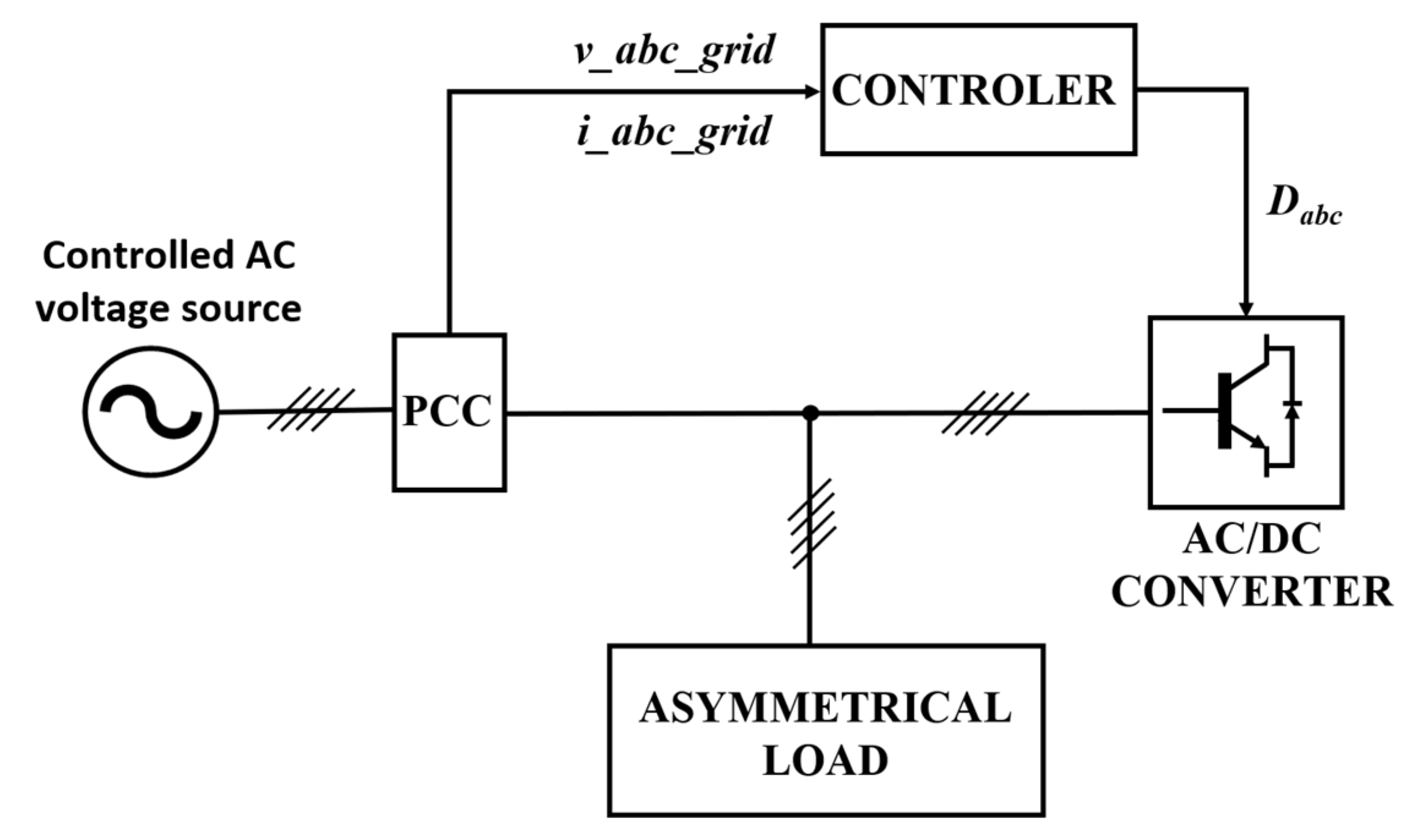
2. Phase-Independent Reactive Power Compensation with the Use of Four-Wire Hybrid Converter with Proportional-Resonant Regulators
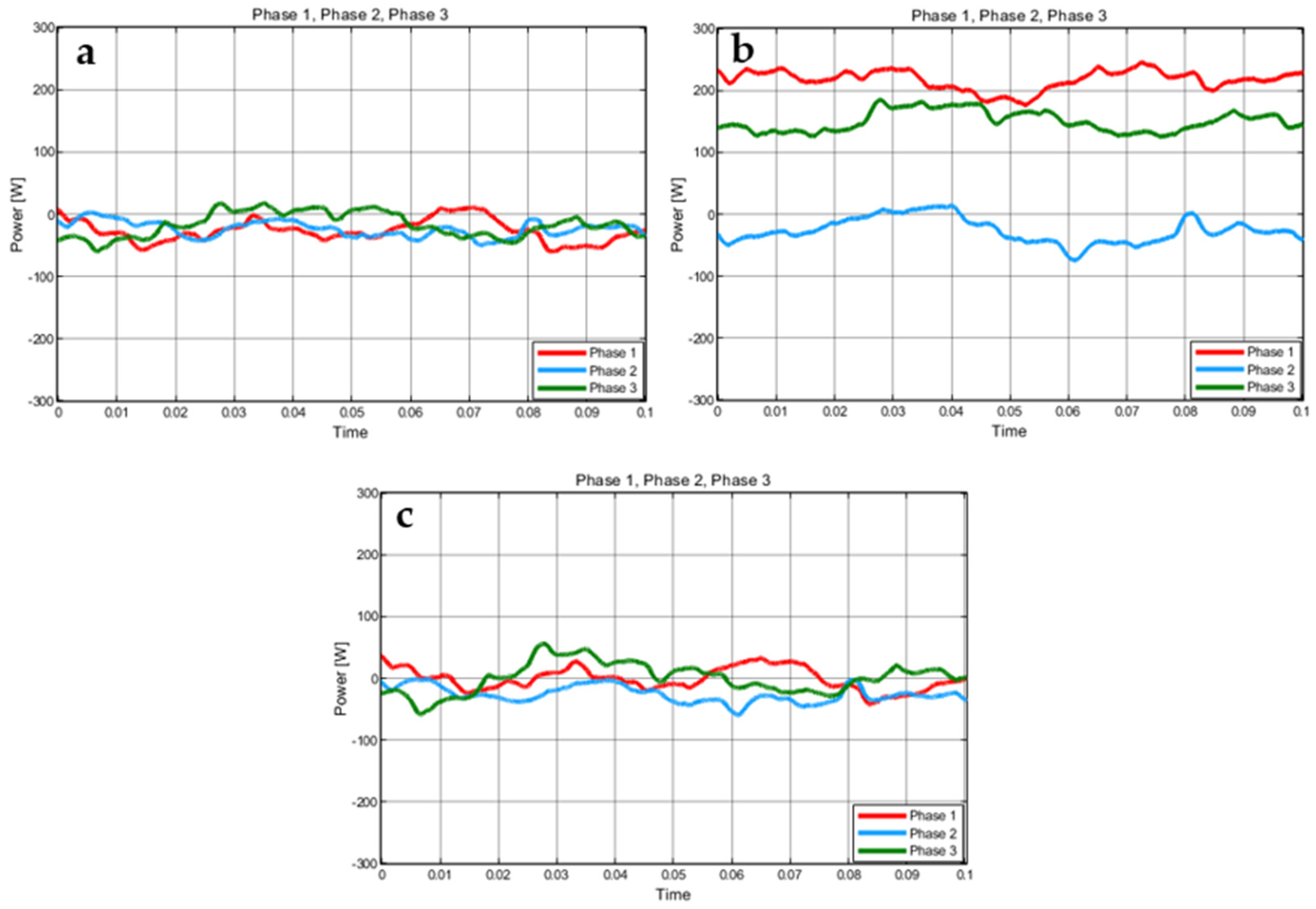
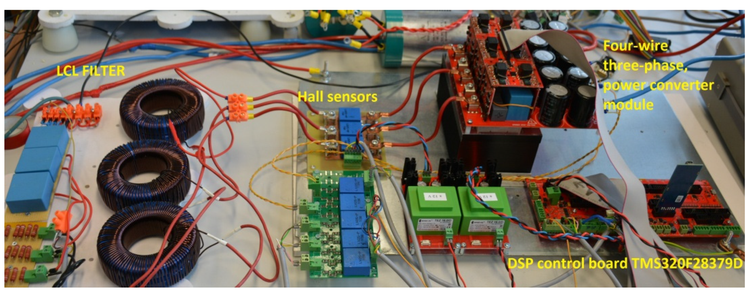
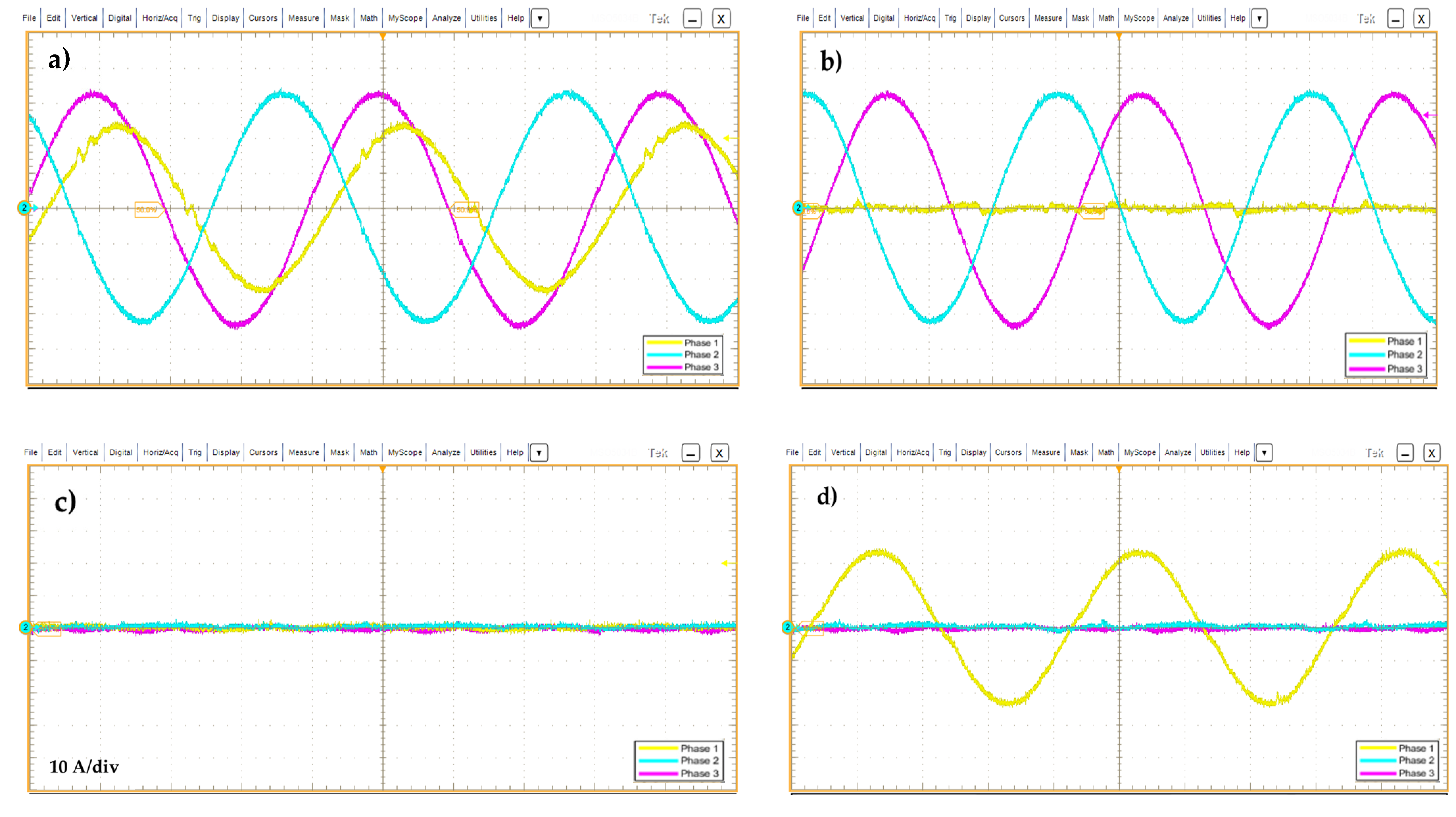
The microgrids are characterized by the fact that their structure includes devices which are working as the current sources. These are generators based on internal combustion engines, electrochemical or mechanical energy storages, and renewable energy sources. All these devices are connected with each other by converters that synchronize with the grid. A typical structure of such a system is shown in Figure 3.
The three-phase converter system for renewable energy sources presented in Figure 3 uses PLL (Phase-locked Loop) systems for synchronization with the grid [17,18,19]. These systems can be divided into those with a system of decomposition into symmetrical components and without this functionality. A common feature of these systems is the generation of a sawtooth signal common to three phases, which maps the actual vector angle of the grid voltage. Unfortunately, the PLL systems used in microgrid-connected three-phase converters do not meet the proper synchronization requirements connected with the angular asymmetry between the individual phases. When this asymmetry is not detected, the unwanted amounts of power will be drawn or delivered by the converters connected to the microgrid system. It should be emphasized that the microgrids are loaded asymmetrically. As a result, the value of active and reactive power is different in each of the phases. Therefore, the developed reactive power compensator should provide phase-independent reactive power compensation in the presence of angular asymmetry between voltage vectors. This type of operation can be achieved by replacing the classical synchronization and power calculation system based on the classical theory of instantaneous power with a solution that takes into account the phase angles of individual phases. The system is complemented by the use of a converter system that enables independent power control for each of the phases, despite the presence of disturbances in the microgrid parameters. The flowchart of the multi-resonant algorithm is presented in Figure 3a.
The proposed solution is a four-wire AC/DC converter (Figure 4). Its construction is based on a three-level T-type topology [20,21,22]. The fourth branch acts as a neutral wire and it enables phase-independent reactive power compensation. This solution is realized by a serial connection of Cx1 and Cx2 capacitors. As a result, the DC bus voltage is split in two. The application of increased capacity on the DC bus improves the operation of the system in dynamic states. In this context, the use of supercapacitors may be considered [23,24]. LN inductance is connected between neutral point and Q13–Q14 transistors. This connection allows for the active voltage stabilization on split DC bus. The inductive-capacitive-inductive (LCL) filter is used at the output of the converter, tuned to eliminate interference from the switching transistors.
Due to the fact that each phase of the converter is controlled independently, the control system was considered as single-phase for further analysis. Subsequently, the system was expanded to three phases during simulation studies.
The main problem which is not mentioned by literature is the proper synchronization with unbalanced phase angles and correct calculation of the converter output currents value. The basic method uses a three-phase synchronous reference frame phase-locked loop (SRF-PLL) [25,26]. The synchronization method generates a sawtooth signal θ, which carries a phase angle value in the range from 0 to 2π.
The synchronization angle θ is used for the calculation of active and reactive current values in the dq frame. This calculation is realized in two steps: The first one is to pass the current signal through the Second-Order Generalized Integrator filter (SOGI), which shifts the measured phase by 90 degrees [27,28]. The second one is the active and reactive current components generation via the Park transform, which is based on the previously calculated signal by the PLL and phase current signal.
[ d q 0 ] = 2 3 [ cos ( θ ) sin ( θ ) 0 sin ( θ ) cos ( θ ) 0 0 0 1 ] × [ α β ]
The method presented in Figure 5a is simple and efficient but causes current calculation errors if the voltage vectors of the weak utility grid are no longer shifted by 120 degrees. Figure 6 presents the value of dq signals as a function of the synchronization angle. Table 1 presents the dq signal value as a function of the small phase error, which is typical for weak utility grids under unbalanced loads. The solution that will overcome these errors is presented in Figure 5b. Instead of a calculation of three 120 degree-shifted signals by a single PLL, three separate PLLs are used to calculate the correct angle of the voltage in each phase independently. In this case, the problem presented in Figure 6 no longer exists: the calculated currents are the base of the active and reactive current control loop.
The diagram and control method of the four-wire converter are shown in Figure 7. This system includes multi-resonant control for single-phase voltage [29,30,31]. The basic system parameters are presented in Table 2:
The control algorithm verifies the amount of reactive power on the basis of the current and voltage measurements at the electrical terminals of a given facility. Reactive power is calculated by the system presented in Figure 5b. The sawtooth synchronization signals generated by the PLLs are converted into a sinewave signal. The sine signals are compared with the current references calculated on the basis of the difference between the demanded and measured reactive power. The next step is to calculate the errors that will be transferred to the inputs of the proportional-resonant regulators by applying negative feedback from the converter’s current. Due to the presence of harmonics in the utility grid, the solution of a multi-resonant regulator is proposed, which consists of multiple proportional-resonant controllers connected in parallel. Next, the signals representing grid voltages are added to the signals from the output of the proportional-resonant regulators and the signals representing the capacitors currents from the LCL filter are subtracted in the same point. The last of the aforementioned feedback loops plays a very important role in stabilizing the converter’s island operation because it constitutes the “virtual damping resistance” of the LCL filter. Finally, the signal, which is the result of the aforementioned control process, is modulated in the pulse width modulation (PWM) module.
The following equations describe the open loop transfer function of the system:
G i = ( K p I _ 1 H + n = 1 , 3 , 5 , 7 , 9 N K i I _ n H 2 ω r c I _ n H s s 2 + 2 ω r c I _ n H s + ω o _ n H 2 ) ( G d K v d c _ f d b k ) G L C L   ·   G n o t c h
where Gi—transfer function of the system, KpI_1H—PI regulator gain, n—the harmonic order, KiI_nH—individual resonant gain for the n-th harmonic, ωrcl_nH—cut-off frequency, ω0—base frequency of the filter, Gd—power converter transfer function, Kvdc_fdbk—DC bus voltage gain, GLCL—LCL filter transfer function, and Gnotch—notch filter transfer function.
G L C L = 1 + R f C f s L 1 C f L 2 s 3 + ( L 1 + L 2 ) R f C f s 2 + ( L 1 + L 2 ) s
where Rf—damping resistance, Cf—LCL filter capacity, L1—the converter side inductor, and L2—the grid side inductor.
G n o t c h = s 2 + 2 · k m i n · d · ω n · s + ω n 2 s 2 + 2 · d · ω n · s + ω n 2  
where Gnotchnotch filter transfer function, kmingain at the notch frequency (in absolute units), d—damping ratio, and ωn—notch frequency (specified in rad/s).
On the basis of the transfer function (2), the Bode plot of the control system in conjunction with the LCL filter has been determined (Figure 8). Bode plot analysis shows that constant and slow-varying signals are integrated. The system response to the signals characterized by frequencies which are slightly below 50 Hz is purely proportional. Bode plot peaks correspond to the fundamental frequency PR controller and its odd multiples. The system also has a low-pass filter with an additional notch filter [32], which is tuned to eliminate the peak at the resonance frequency of the LCL filter.

3. Tests Results

For the simulation tests, a microgrid with single-phase loads and an AC/DC converter operating in the reactive power compensator mode was modeled. The active power reference was equal to zero in all simulation cases. In the first case, the oscillogram (Figure 9a) showed the power delivered by the converter to the symmetrically loaded microgrid. For synchronization purposes, the system with standard three phase-based PLL was used (Figure 5a). The active power delivered by the converter was close to zero. In the second case (Figure 9b), resistive, inductive, and capacitive loads were connected to the individual phases of the microgrid, which resulted in voltage unbalance. As in the previous case, a standard PLL was used for synchronization (Figure 5a). The converter’s output power was close to zero in the first phase, approximately 150 W in the second phase, and slightly over 200 W in the third phase. The third oscillogram (Figure 9c) showed the case where the loads remained the same as in the second case but the synchronization method was changed by introducing three individual PLLs (Figure 5b). As a result, the active power flow generated by the converter in all three phases was close to zero. It can be clearly stated that the synchronization system based on three individual PLLs has a good level of performance in the state of voltage unbalance.
The test bench for determining the effectiveness of the reactive power compensation in the individual phases of the microgrid was set up according to Figure 10. The research was carried out with the use of the hybrid AC/DC converter in a three-phase four-wire configuration (Figure 10 and Figure 11), Chroma 6512 programmable three-phase AC source, and three-phase reactive load. The research was divided into three main parts. The first two show the correctness of the reactive power compensation at a variable reactive load; in this state, the converter outputs only the reactive power. The third part presents the influence of the angular asymmetry between voltage vectors on the correctness of the output active and reactive power. An example with the single synchronization system is presented, as well as a proposed algorithm that makes the converter independent of angular errors.
The first variant involved loading the first phase with 3.7 kvar capacitive reactive power and the other two phases with 5 kW active power per phase. The second variant involved loading the first phase with 3.7 kvar capacitive reactive power, the second phase with 2 kvar inductive reactive power, and the third phase with 5 kW of the active power. All tests were conducted at the same voltage level: 230 V.
In the first laboratory test, the flow of reactive power was caused entirely by the capacitive load in the first phase (Figure 12a). The second and third phase load was resistive, therefore all the power delivered by the programmable AC source Chroma 6512 in these phases was active. Reactive power compensation reduced the reactive current flow from the programmable AC source to zero (Figure 12b). During compensation, the programmable AC source provided only the active power consumed by the resistive loads on two phases. The fulfilment of this condition allows for reducing the flow of reactive power at the output of the converter in an idle state to zero (Figure 12c). The reactive current flow, forced by the converter (Figure 12d), fully covers the demand of the loads, thus the programmable AC source does not have to transfer any reactive power to the load.
In the second test, due to the capacitive load in the first phase and inductive load in the second phase, the flow of reactive power in these phases was detected (Figure 13a). The third phase load was resistive, therefore all the power given off by the programmable AC source in this phase was active. Reactive power compensation reduced the reactive currents flow from the programmable AC source to almost zero. The fulfilment of this condition allows for reducing the flow of reactive power at the output of the converter in an idle state to zero (Figure 13c). The reactive current flow, forced by the converter (Figure 13d), fully covers the demand of the loads, thus the programmable AC source does not have to transfer any reactive power to the load.
Figure 14 presents the comparison between two considered synchronization methods from the grid perspective. It is worth noticing that in Figure 14a, the active power is non-zero in individual phases. The converter generated 74.8 W in the second phase and 28.6 W in the third phase. This is due to the use of the standard three phase-based synchronization method. This test is an empirical confirmation of the simulation that included the operation of the converter with the above-mentioned synchronization algorithm (Figure 9b). In the simulation, the active power delivered by the inverter was greater than in the test result because a deeper angular asymmetry was modeled. This is an undesirable situation because the active current can discharge AC/DC converter capacitors and then drain the power from prosumer energy storage. On the other hand, when the improved compensation algorithm was applied (Figure 5b), the active current from the output of the power converter is almost zero; this is preferred situation because the active and reactive current is measured without the error caused by phase angle unbalance (Figure 14b). Simulation studies also showed high effectiveness of the improved synchronization method in reducing undesirable active power flow. Despite the small error of angles between voltage vectors, the active current is almost negligible and discharging of the capacitive DC-link or prosumer energy storage does not occur. The use of the proposed compensation method reduced the error of active power output by 97.97%.

4. Summary

The article presented the problem of reactive power compensation in the local microgrids. The analysis of the available solutions showed that the commonly used devices are characterized by low operation dynamics and are not able to fully compensate the generated reactive power for the individual phases of the system. Additionally, the currently available solutions are designed for three-phase symmetrical operation. The paper presented a solution based on a three-phase, four-wire AC/DC power converter with a separate neutral wire and reactive power compensation algorithm which is immune to unbalanced grid conditions. The applied control algorithm is based on the digital implementation of the multi-resonant algorithm, two-variant PLL module, and power analysis subsystem. Based on laboratory tests results, it has been proven that a better solution is to use a system with three individual PLLs and Park transforms in the case when the microgrid is in the angular asymmetry state. The difference between using the standard approach (Figure 5a) and the proposed approach (Figure 5b) was presented. The final conclusion shows that the utilization of the three-level, four-wire converter with independent control of individual phases has a high potential for reactive current compensation in the case of microgrids, but the correct algorithm for proper synchronization must be applied. Laboratory tests presented in Figure 14a,b showed that the proposed algorithm operates properly with a weak microgrid and it is able to reduce active power on the output of the reactive power compensator from 103.5 W to 2.1 W, which can prevent the discharge of the DC link of converter and prosumer energy storages.

Author Contributions

Conceptualization, D.Z.; methodology, D.Z.; software, D.Z., B.S. and K.J.; validation, D.Z., B.S. and K.J.; formal analysis, D.Z.; investigation, B.S.; resources, D.Z.; data curation, B.S. and K.J.; writing—original draft preparation, D.Z., B.S. and K.J.; writing—review and editing, D.Z., B.S. and K.J.; visualization, B.S. and K.J.; supervision, D.Z.; project administration, D.Z.; funding acquisition, D.Z. All authors have read and agreed to the published version of the manuscript.

Funding

This research received no external funding.

Institutional Review Board Statement

Not applicable.

Informed Consent Statement

Not applicable.

Data Availability Statement

Not applicable.

Acknowledgments

This work was supported under the project “Management of low-voltage distribution network operation with prosumers’ active participation” of the Polish National Centre for Research and Development, project no. POIR.04.01.02-00-0007/17, European Funds of the Smart Growth Operational Programme 2014–2020.

Conflicts of Interest

The authors declare no conflict of interest.

References

  1. Awad, F.H.; Mansour, A.A.; Marei, M.I.; Sattar, A.A. Compensation the Unbalance of Non-Linear Load Based on Three-Leg Center-Split Inverter Four Wire. In Proceedings of the 6th International Conference on Advanced Control Circuits and Systems (ACCS) & 5th International Conference on New Paradigms in Electronics & information Technology (PEIT), Hurgada, Egypt, 17–20 November 2019; pp. 229–236. [Google Scholar]
  2. Meersman, B.; Renders, B.; Degroote, L.; Vandoorn, T.; Vandevelde, L. Control design of grid-connected three-phase inverters for voltage unbalance correction. In Proceedings of the 44th International Universities Power Engineering Conference (UPEC), Glasgow, UK, 1–4 September 2009; pp. 1–5. [Google Scholar]
  3. Mishra, M.K.; Ghosh, A.A.; Joshi, A.; Suryawanshi, H.M. A Novel Method of Load Compensation under Unbalanced and Distorted Voltages. IEEE Trans. Power Deliv. 2007, 22, 288–295. [Google Scholar] [CrossRef] [Green Version]
  4. Vechium, I.; Camblong, H.; Tapia, G.; Curea, O.; Dakyo, B. Modelling and control of four-wire voltage source inverter under unbalanced voltage condition for hybrid power system applications. In Proceedings of the European Conference on Power Electronics and Applications, Dresden, Germany, 11–14 September 2005; p. 10. [Google Scholar]
  5. Tan, K.-H.; Lin, F.-J.; Chen, J.-H. A Three-Phase Four-Leg Inverter-Based Active Power Filter for Unbalanced Current Compensation Using a Petri Probabilistic Fuzzy Neural Network. Energies 2017, 10, 2005. [Google Scholar] [CrossRef] [Green Version]
  6. Ning-Yi, D.; Wong, M.C.; Han, Y.D. Application of a three-level NPC inverter as a three-phase four-wire power quality compensator by generalized 3DSVM. IEEE Trans. Power Electron. 2006, 21, 440–449. [Google Scholar] [CrossRef]
  7. Saber, B.; Abdelkader, B.; Said, B.; Mansour, B.B. Neutral Current Compensation of Three-Phase Four-wire Distribution System Using Three-Level Four-Leg DSTATCOM Based on Simplified 3DSVM Algorithm. In Proceedings of the 2018 6th International Conference on Control Engineering & Information Technology (CEIT), Istanbul, Turkey, 25–27 October 2018; pp. 1–6. [Google Scholar]
  8. Krishna, T.N.V.; Sathishkumar, P.; Himasree, P.; Punnoose, D.; Raghavendra, K.V.G.; Himanshu; Naresh, B.; Rana, R.A.; Kim, H.-J. 4T Analog MOS Control-High Voltage High Frequency (HVHF) Plasma Switching Power Supply for Water Purification in Industrial Applications. Electronics 2018, 7, 245. [Google Scholar] [CrossRef] [Green Version]
  9. Krishna, T.N.V.; Himasree, P.; Rao, S.S.; Kumar, Y.A.; Kundakarla, N.B.; Kim, H.J. Design and Development of a Digital Controlled Dielectric Barrier Discharge (DBD) AC Power Supply for Ozone Generation. J. Sci. Ind. Res. 2020, 79, 1057. [Google Scholar]
  10. Narayanan, N.; Shan, S.; Umanand, L. Stability Analysis of Phase Locked Loop Controllers for Grid Tied Inverters in Weak Microgrids. In Proceedings of the 2018 IEEE International Conference on Power Electronics, Drives and Energy Systems (PEDES), Chennai, India, 18–21 December 2018; pp. 1–5. [Google Scholar]
  11. Adib, A.; Mirafzal, B.B.; Wang, X.; Blaabjerg, F. On Stability of Voltage Source Inverters in Weak Grids. IEEE Access 2018, 6, 4427–4439. [Google Scholar] [CrossRef]
  12. Dickert, J.; Domagk, M.; Schegner, P. Benchmark low voltage distribution networks based on cluster analysis of actual grid properties. In Proceedings of the 2013 IEEE Grenoble Conference, Grenoble, France, 16–20 June 2013; pp. 1–6. [Google Scholar]
  13. Kaipia, T.; Peltoniemi, P.; Lassila, J.; Salonen, P.; Partanen, J. Impact of low voltage DC system on reliability of electricity distribution. In Proceedings of the 20th International Conference and Exhibition on Electricity Distribution CIRED—Part 1, Prague, Czech Republic, 8–11 June 2009; pp. 1–4. [Google Scholar]
  14. Darbali-Zamora, R.; Ortiz-Rivera, E.I. An Overview into the Effects of Nonlinear Phenomena in Power Electronic Converters for Photovoltaic Applications. In Proceedings of the 2019 IEEE 46th Photovoltaic Specialists Conference (PVSC), Chicago, IL, USA, 16–21 June 2019; pp. 2908–2915. [Google Scholar]
  15. Albana, I. Effects of the Reactive Power Injection on the Grid—The Rise of the Volt/var Interaction Chain. Smart Grid Renew. Energy 2016, 7, 217–232. [Google Scholar]
  16. Islam, M.; Mithulananthan, N.; Hossain, J.; Shah, R. Dynamic voltage stability of unbalanced distribution system with high penetration of single-phase PV units. In Proceedings of the The 9th International Conference on Power Electronics, Machines and Drives (PEMD 2018), Liverpool, UK, 17–19 April 2018; pp. 4074–4080. [Google Scholar]
  17. Zieliński, D.; Lipnicki, P.; Jarzyna, W. Synchronization of voltage frequency converters with the grid in the presence of notching. COMPEL—Int. J. Comput. Math. Electr. Electron. Eng. 2015, 34, 657–673. [Google Scholar] [CrossRef]
  18. Peña Asensio, A.; Gonzalez-Longatt, F.; Arnaltes, S.; Rodríguez-Amenedo, J.L. Analysis of the Converter Synchronizing Method for the Contribution of Battery Energy Storage Systems to Inertia Emulation. Energies 2020, 13, 1478. [Google Scholar] [CrossRef] [Green Version]
  19. Rizqiawan, A.; Hadi, P.; Fujita, G. Development of Grid-Connected Inverter Experiment Modules for Microgrid Learning. Energies 2019, 12, 476. [Google Scholar] [CrossRef] [Green Version]
  20. Zhang, L.; Shi, D.; Jiang, W.; Yang, T.; Jin, C.; Zhang, Y.; Loh, W.K.; Tang, Y. Three-Phase-Four-Wire Three-Level Inverter with Neutral Inductor and Neutral Module for Saving AC-Filter-Inductances and DC-Link-Capacitances. In Proceedings of the IEEE Energy Conversion Congress and Exposition (ECCE), Detroit, MI, USA, 11–15 October 2020; pp. 5656–5661. [Google Scholar]
  21. Peng, H.; Yuan, Z.; Woldegiorgis, D.L.; Emon, A.I.; Narayanasamy, B.; Liu, Y.; Luo, F.; Mantooth, A.; Mhiesan, H.G. Practical Design and Evaluation of a High-Efficiency 30-kVA Grid-Connected PV Inverter with Hybrid Switch Structure. In Proceedings of the IEEE Energy Conversion Congress and Exposition (ECCE), Detroit, MI, USA, 11–15 October 2020; pp. 3670–3676. [Google Scholar]
  22. Yuan, Z.; Deshpande, A.; Narayanasamy, B.; Peng, H.; Emon, A.I.; Whitt, R.; Nafis, B.M.; Luo, F.; Huitink, D. Design and Evaluation of A 150 kVA SiC MOSFET Based Three Level TNPC Phase-leg PEBB for Aircraft Motor Driving Application. In Proceedings of the IEEE Energy Conversion Congress and Exposition (ECCE), Baltimore, MD, USA, 29 September–3 October 2019; pp. 6569–6574. [Google Scholar]
  23. Kumar, Y.A.; Kim, H.-J. Effect of Time on a Hierarchical Corn Skeleton-Like Composite of CoO@ZnO as Capacitive Electrode Material for High Specific Performance Supercapacitors. Energies 2018, 11, 3285. [Google Scholar] [CrossRef] [Green Version]
  24. Yedluri, A.K.; Anitha, T.; Kim, H.-J. Fabrication of Hierarchical NiMoO4/NiMoO4 Nanoflowers on Highly Conductive Flexible Nickel Foam Substrate as a Capacitive Electrode Material for Supercapacitors with Enhanced Electrochemical Performance. Energies 2019, 12, 1143. [Google Scholar] [CrossRef] [Green Version]
  25. Rodriguez, P.; Pou, J.; Bergras, J.; Candela, J.I.; Burgos, R.P.; Boroyevich, D. De-coupled double synchronous reference frame PLL for power converters control. IEEE Trans. Power Electron. 2007, 22, 584–592. [Google Scholar]
  26. Jarzyna, W.; Zieliński, D.; Gopakumar, K. An evaluation of the accuracy of in-verter sync angle during the grid’s disturbances. Metrol. Meas. Syst. 2020, 27, 355–371. [Google Scholar]
  27. Jarzyna, W. A survey of the synchronization process of synchronous generators and power electronic converters. Bull. Pol. Acad. Sci. Tech. Sci. 2019, 67, 67,1069–1083. [Google Scholar]
  28. Nicastri, A.; Nagliero, A. Comparison and evaluation of the PLL techniques for the design of the grid-connected inverter systems. In Proceedings of the IEEE International Symposium on Indus-trial Electronics, Bari, Italy, 4–7 July 2010; pp. 3865–3870. [Google Scholar]
  29. Li, Y.; Tsai, T.; Yang, C.; Chen, Y.; Chang, Y. Per-Phase Control Strategy of the Three-Phase Four-Wire Inverter. In Proceedings of the International Power Electronics Conference, Niigata, Tokio, 20–24 May 2018; pp. 883–888. [Google Scholar]
  30. Serban, E.; Pondiche, C.; Ordonez, M. Power-loss analysis in 3-level TNPC inverters: Modulation effects. In Proceedings of the IEEE Energy Conversion Congress and Exposition (ECCE), Cincinnati, OH, USA, 1–5 October 2017; pp. 490–497. [Google Scholar]
  31. Iturra, R.G.; Thiemann, P. A Simple SiC MOSFETs Three Level Inverter Topology for High Performance Shunt Active Power Filter. In Proceedings of the 21st European Conference on Power Electronics and Applications, Genova, Italy, 2–5 September 2019; pp. 1–10. [Google Scholar]
  32. Lee, K.-J.; Lee, J.-P.; Shin, D.; Yoo, D.-W.; Kim, H.-J. A Novel Grid Synchronization PLL Method Based on Adaptive Low-Pass Notch Filter for Grid-Connected PCS. IEEE Trans. Ind. Electron. 2013, 61, 292–301. [Google Scholar] [CrossRef]
Figure 1. The angular asymmetry between voltage vectors: reference grid measurement.
Energies 15 00497 g001
Figure 2. The angular asymmetry between voltage vectors: microgrid measurement.
Energies 15 00497 g002
Figure 3. (a) Typical control structure of a converter integrated with renewable energy sources. (b) The flowchart of the multi-resonant algorithm. I*q, I*d—Reference current value in dq frame; Id, Iq—feedback currents after Park transform; Vdq—voltage signals in dq frame; Ig_abc, Vg_abc—Three phase instantaneous currents and voltages. Vinv_abc—three phase reference signals for PWM module.
Energies 15 00497 g003
Figure 4. Hybrid converter in a three-phase, three-level four-wire configuration to enable the phase-independent reactive power compensation.
Energies 15 00497 g004
Figure 5. The method of active and reactive power calculation. (a) System with standard three phase-based PLL signal. (b) System with three individual PLL signals, which is the proposed method for the presence of angular asymmetry between voltage vectors.
Energies 15 00497 g005
Figure 6. The changes of d and q components on the Park transform output as a function of phase angle.
Energies 15 00497 g006
Figure 7. Simplified algorithm of multi-resonant converter control for single phase.
Energies 15 00497 g007
Figure 8. Bode plot of multi-resonant control system.
Energies 15 00497 g008
Figure 9. The results of simulation tests for (a) symmetrical loads and standard PLL, (b) asymmetrical loads and standard PLL, (c) asymmetrical loads with proposed three individual PLLs.
Energies 15 00497 g009
Figure 10. Test bench block diagram: three-phase AC/DC converter system for reactive power compensation.
Energies 15 00497 g010
Figure 11. Experimental setup used in laboratory tests.
Energies 15 00497 g011
Figure 12. Programmable AC source currents (measured at PCC point): (a) AC source loaded without AC/DC converter connection, (b) connected AC/DC converter operating in reactive power compensation mode, and (c) reactive power compensation in the idle state of the AC source. (d) The coverage of reactive current demand by the AC/DC converter.
Energies 15 00497 g012
Figure 13. Programmable AC source currents (measured at PCC point): (a) AC source loaded without AC/DC converter connected, (b) connected AC/DC converter operating in reactive power compensation mode, and (c) reactive power compensation in the idle state of the AC current source. (d) The reactive current flow forced by the converter AC/DC.
Energies 15 00497 g013aEnergies 15 00497 g013b
Figure 14. Programmable AC source measurements (at PCC point) without (a) and with (b) three individual one-phase PLL synchronization modules.
Energies 15 00497 g014
Table 1. The changes of d and q components as a function of the phase angle.
Phase
Error [deg.]
dq
10.9990.017
30.9980.052
50.9960.087
100.9850.173
Table 2. Hybrid AC/DC converter parameters.
PropertiesValue
Output power (kVA)10
Switching frequency of AC/DC modules (kHz)20
DC bus voltage of the AC/DC converter (V)750
DC bus capacity (mF)10
LCL filter cut-off frequency (kHz)2.8
THDi (at load above 50%; %)
Efficiency
<1
94%
Publisher’s Note: MDPI stays neutral with regard to jurisdictional claims in published maps and institutional affiliations.

