
Archimedes Screw Design: An Analytical Model for Rapid Estimation of Archimedes Screw Geometry


School of Engineering, University of Guelph, 50 Stone Rd E, Guelph, ON N1G 2W1, Canada
*
Author to whom correspondence should be addressed.
Energies 2021, 14(22), 7812; https://doi.org/10.3390/en14227812
Submission received: 29 October 2021
/
Revised: 11 November 2021
/
Accepted: 12 November 2021
/
Published: 22 November 2021
(This article belongs to the Special Issue Energy Conversion System – Small Hydropower Plants)
Abstract
:In designing Archimedes screws, determination of the geometry is among the fundamental questions that may affect many aspects of the Archimedes screw powerplant. Most plants are run-of-river and highly depend on local flow duration curves that vary from river to river. An ability to rapidly produce realistic estimations for the initial design of a site-specific Archimedes screw plant helps to facilitate and accelerate the optimization of the powerplant design. An analytical method in the form of a single equation was developed to rapidly and easily estimate the Archimedes screw geometry for a specific site. This analytical equation was developed based on the accepted, proved or reported common designs characteristics of Archimedes screws. It was then evaluated by comparison of equation predictions to existing Archimedes screw hydropower plant installations. The evaluation results indicate a high correlation and reasonable relative difference. Use of the equation eliminates or simplifies several design steps and loops and accelerates the development of initial design estimations of Archimedes screw generators dramatically. Moreover, it helps to dramatically reduce one of the most significant burdens of small projects: the nonscalable initial investigation costs and enables rapid estimation of the feasibility of Archimedes screw powerplants at many potential sites.
1. Introduction
The Archimedes screw (also known as an Archimedean or hydrodynamic screw) is one of the earliest hydraulic machines [1]. Using Archimedes screws as water pumps dates back many centuries. In the modern world, Archimedes screw pumps (ASP) are widely used in wastewater treatment plants and for dewatering low-lying regions. The Archimedes screw generator (ASG) is a safer hydropower technology for aquatic life, especially fish [2,3,4,5,6,7,8,9], that has been in use since the 1990s [10]. The Archimedes screw is a reversible hydraulic machine, and there are several examples of Archimedes screw installations where the screw can operate at different times as either pump or generator, depending on needs for power and watercourse flow [11].
When designing an ASG, estimation of the screw geometry is a fundamental necessity. The screw geometry affects many aspects of an Archimedes screw powerplant design. Each site has different specifications and limitations, including head, flow and available locations for the power plant installation. Most ASG installations are run-of-river, with small or no reservoirs, and plant performance is directly dependent on the local flow duration curve which varies from river to river. The lack of active water storage in run-of-river (ROR) powerplants makes the importance of the temporal distribution of volumetric flow rate an important design parameter. This means that ASG designs must be highly site-specific, requiring different designs to account for site-specific characteristics.
Recently there has been an emerging interest using computational fluid dynamics (CFD) in the modeling of Archimedes screw turbines to measure and visualize the fluid and forces within the screw. Simmons [12,13] and Shahverdi have completed CFD studies modelling several case studies to study ASG performance [14], optimize screw performance [15], or assess and predict the design parameters of the Archimedes screw generator [16]. However, these studies demonstrate that successful CFD modelling requires significant time, resources and experienced practitioners, software and hardware infrastructures. Proper CFD models must be carefully developed, validated and analyzed for each case.
Archimedes screw pumps (ASP) could be considered among the well-studied hydraulic machines, and some analytical methods are available [17], however in practice some aspects of ASP design remain based on experience. There is also a lack of analytical guidelines for ASG design. At the current time, insufficient general design guidelines could be considered as an important disadvantage for ASGs [18]. The literature shows that there are still no general analytical standards for designing ASGs [18], and the designs are still highly dependent on the designer’s experience [19]. Important non-English language ASG design literature includes the works of Brada (1996) [20], Aigner (2008) [21], Schmalz (2010) [22], Lashofer et al. (2011) [23], and Nuernbergk’s (2020) book [24]. The papers by Rorres [25] and Nuernbergk and Rorres [19] are among the well-known studies in English literature. However, the proposed methods in these works are not easy to understand and implement [18], particularly at the first stage of plant design.
Dragomirescu (2021) proposed a method to estimate the required screw outer diameter based on the volume of filled buckets [17]. However, there was no analytical equation to calculate this volume. To deal with this issue, Dragomirescu used regression to estimate correction factors based on a list of ASGs that were all designed by the same manufacture (Rehart Power) [25] and selected based on their high overall plant efficiencies (more than 60%) [17]. Using regression analysis for such limited case studies may affect the generality of the model and limit it to these case studies. However, in comparison to the former studies, this method resulted in a method to quickly estimate required screw size that was easier to understand and implement.
Currently, there is no generally accepted and easy to understand and implement method to rapidly determine preliminary size and operating characteristics of ASG designs. Obviously, each design requires deep studies, evaluation, modelling and optimization, which is costly and time-consuming. However, the first step of optimizing a design is to develop realistic estimates of the primary variables for the initial designs. Therefore, a model is needed for the purpose of rapidly estimating initial design parameters. This study focuses on developing an analytical method to estimate site-specific Archimedes screw geometry properties rapidly and easily.
2. Materials and Methods
2.1. Theoretical Basis
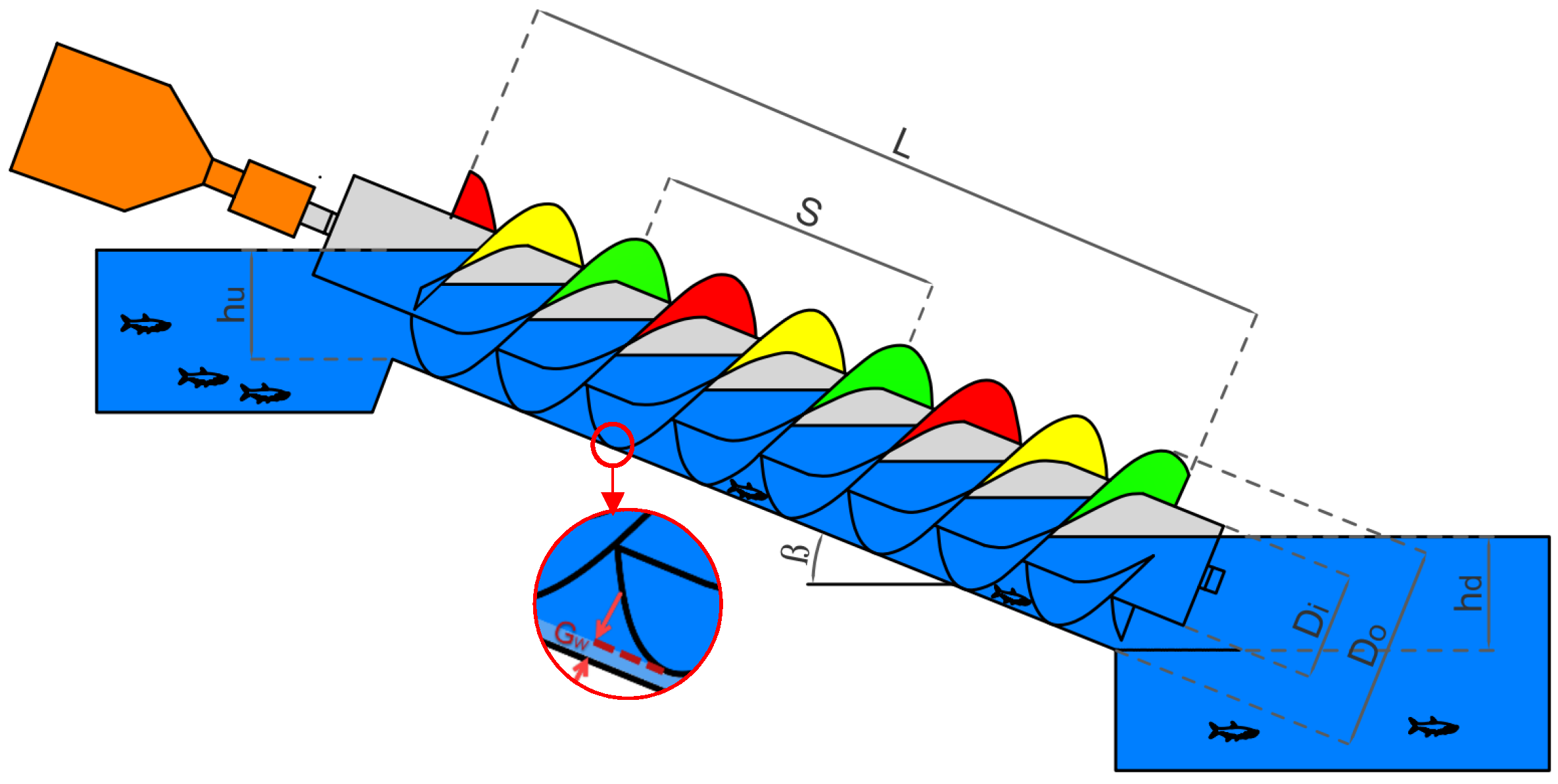
An Archimedes screw is made of a helical array of blades wrapped around a central cylinder [26] and supported within a fixed trough with small gap that allows the screw to rotate freely [18]. The most important dimensions and parameters required to define the Archimedes screws are represented in Figure 1 and described in Table 1.
The inlet depth of the Archimedes screw can be represented in a dimensionless form as:
The available head (H) and volumetric flow rate (Q) and are two important parameters in hydropower plants. In Archimedes screws, the flow always has a free surface (exposed to atmospheric pressure). In addition, the cross-sectional areas at the inlet and outlet of a screw are equal. Applying continuity and the Bernoulli equation, it can be shown that ideally, the available head at an ASG is the difference of free surface elevations at the upstream (ZU) and downstream (ZL) of the AST, where ZU and ZL are both measured from the same datum:
The inclination angle of the Archimedes screw (β) is sometimes restricted based on slope or geometry. Considering Figure 1, for a known head the screw length (L) is:
For development of the current predictive model, application of the continuity equation suggests that the flow rate passing through the screw (Q) is dependent on the flow depth at the entrance (hu) overall (outer) diameter () and the rotation speed (ω) of the screw. This assumption is applied and evaluated formerly in studies such as Nuernbergk and Rorres [19] and YoosefDoost and Lubitz [28].
In Archimedes screws, a water bucket is a volume of entrapped water between two adjacent helical plane surfaces. For an ideal screw operating under steady-state conditions (steady flow, constant rotational speed), all buckets will have the same shape and volumetric size [29]. Moreover, it could be assumed that the flow has a speed equal to the screw axial translation speed () which is equal to:
In 1932 Muysken proposed the required equations and design parameters for Archimedes screws used as pumps [30]. Muysken proposed a maximum recommended rotation speed () for Archimedes screws [30], and Lashofer et al. [10] confirmed that many current industrial ASGs are designed with this rotation speed which is close to:
YoosefDoost and Lubitz proposed a nondimensional equation to estimate the total flow rate passing through an Archimedes screw for rotation speeds equal or different than Muysken’s maximum rotation speed, different inlet water levels and screw sizes as [28]:
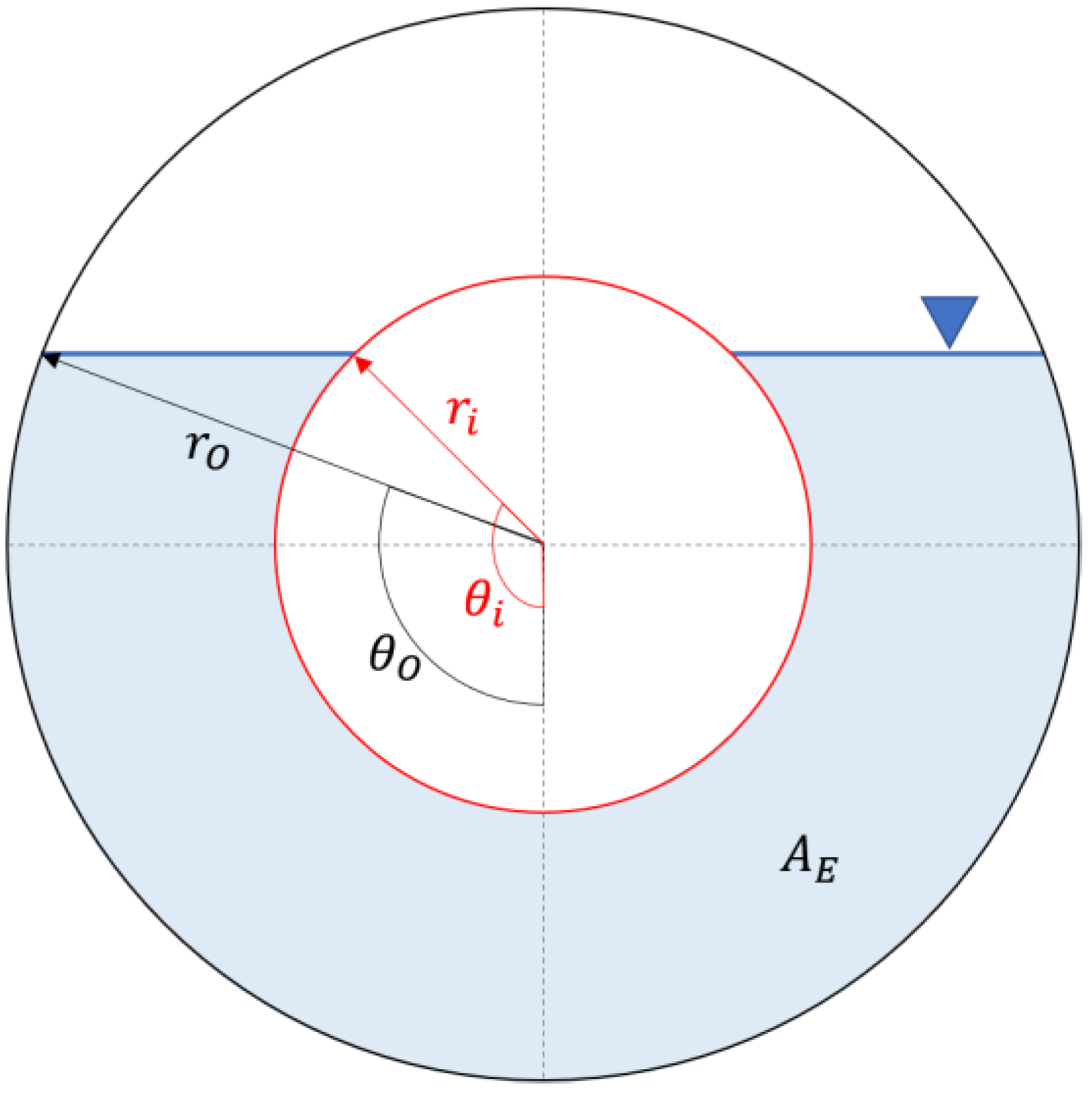
where , and and are constants related to the screw’s properties. The effective area () is calculated using the following equations, with the definitions of additional variables defined in Figure 2.
Although the optimum value may be different for each screw, studies on a range of lab-scale (small) and full-scale Archimedes screw sizes showed that values of , , and . resulted in reasonable predicted flow rates [28].
For optimal design of industrial full-scale Archimedes screws running at a fixed speed near Muysken’s maximum recommended rotation speed (ωM) [30], Nuernbergk and Rorres proposed an analytical method based on the screw’s water-inflow conditions [19]. This method can be simplified to an equation which is a function of the inlet depth, rotation speed and geometry of the screw using the method proposed by YoosefDoost and Lubitz (2021) based on the concept of the effective cross-sectional area within the screw (), and using the axial transport velocity of Archimedes screws () [28]:
where and . Using the concept of effective area () with Equations (4) and (8) and defining and results in the following analytical equation for the volume of flow passing through the Archimedes screw:
The overall (outer) diameter of the screw () can then be determined based on the flow rate passing through the screw. Solving for the outer diameters results in the following equation that enables estimation of the required Archimedes screw outer diameter to accommodate the specified flow rate passing through the screw:
These equations could be simplified for industrial full-scale Archimedes screws running at a fixed speed near to the Muysken’s maximum recommended rotation speed () as:
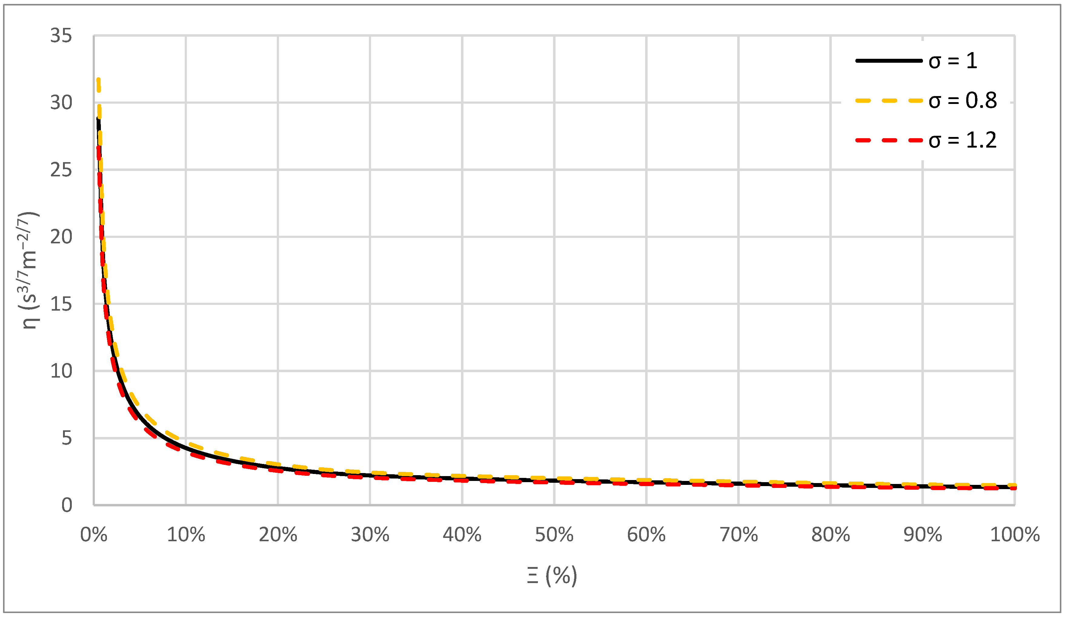
It is notable that for a specific screw at a specific fill level, the variables other than Q are constant, and the form of Equation (13) could be represented as a power function with two constants of and :
The inner diameter of the screw () has an important effect in and the flow rate passing through the screw. In smaller screws, it is possible to deal with technical constraints such as permissible deflection by increasing the thickness of the shaft tube wall. However, to maximize the shaft length, it may be necessary to increase the outer diameter. Nagel in 1968 indicated that reasonable filling of ASPs would be achieved for between 0.4 and 0.6 [31]. Theoretical studies and experimental investigations on models and full-scale ASPs indicate that maximizing the water volume in the screw occurs with between 0.45 and 0.55. This ratio is reported as the economically optimum ratio as well, due to optimum the usage of material [31]. Lashofer et al. [10] confirmed that for most ASG powerplants, is usually very close to 0.5.
Nagel in 1968 indicated the ratio of is related directly to the number of blades (N) and reversely to the inclination angle (β) of the ASPs (higher β or lower N results in lower δ, and vice versa). From the hydraulic point of view, Nagel recommends [10]:
Figure 3 compares the results of Equation (14) for the proposed values across the full range of dimensionless fill heights () of screws with . An analysis of this result indicates that and . Due to manufacturing considerations, Nagel proposed to consider as a fixed ratio (constant) and the inclination angle as a parameter to optimize [10]. The is proven as a correct ratio for ASPs with three blades and inclination angles up to [31]. Lashofer et al. confirmed that two-thirds of AST installations follow this ratio and the rest utilized larger variations, most likely as a result of the installation conditions [10].
As a general analytical method to estimate the Archimedes screw outer diameter based on the volumetric flow rate for all AST inlet depths, Equation (14) could be applied for , , and the corresponding value of each dimensionless inlet depth.
The observations above can be used to determine an overall relationship between volume flow rate and outer diameter for a screw. The general form of Equation (15) is:
where is a constant accounting for screw geometry and fill level. Assuming the commonly used values of and , a value of can be determined for each dimensionless inlet depth, which is turn is related to volume flow rate.
This resulting analytical equation eliminates the requirement of many design steps and loops and simplifies and accelerates the design of Archimedes screw dramatically. For example, for the known flow rate of Q, Equation (16) could be used for any Archimedes screw with , and Figure 3 could be used to determine the corresponding value of each dimensionless inlet depths. It is noteworthy that for and , Equations (12) and (13) could be simplified as:
Moreover, it is worth mentioning that as a check, solving the same problem for different ASG inlet fill heights leads to results that are in complete agreement with Equation (16). For example, analytical solving of the problem or using Equation (18) for and gives the following values, respectively:
2.2. Evaluation Criteria
In this study the estimations () are compared with the industrial ASGs represented in Table 2 as observations (), by visualizations and statistical tests. Correlation is compared by Pearson correlation (R), and the relative difference is compared by the percentage error (PE) and mean absolute percentage error (MAPE). In the following equations, n is the number of data points and and are the average of the estimations and observations respectively [28].
In statistics, correlation refers to any statistically significant relationship between two variables. The Pearson correlation coefficient measures the linear relationship between two random variables [32] and describes it in a range between −1 to +1. Values close to +1 indicate a good and direct correlation, while values closer to −1 refer to a good but inverse relation between datasets. Values near zero indicate a lack of correlation [33]. These ranges could be represented in percent by multiplying the Pearson correlation by 100. The Pearson correlation is defined as [34]:
The percentage (percent) error (PE) is a dimensionless error measure defined as the difference between the model estimations and the experimentally measured value:
The mean absolute percentage error (MAPE) is the average of absolute percentage errors and one of the most common accuracy measures [35] that is recommended in many textbooks (e.g. [36,37]). MAPE considers errors regardless of their sign, so positive and negative errors cannot cancel each other. MAPE is calculated as:
3. Results and Analysis
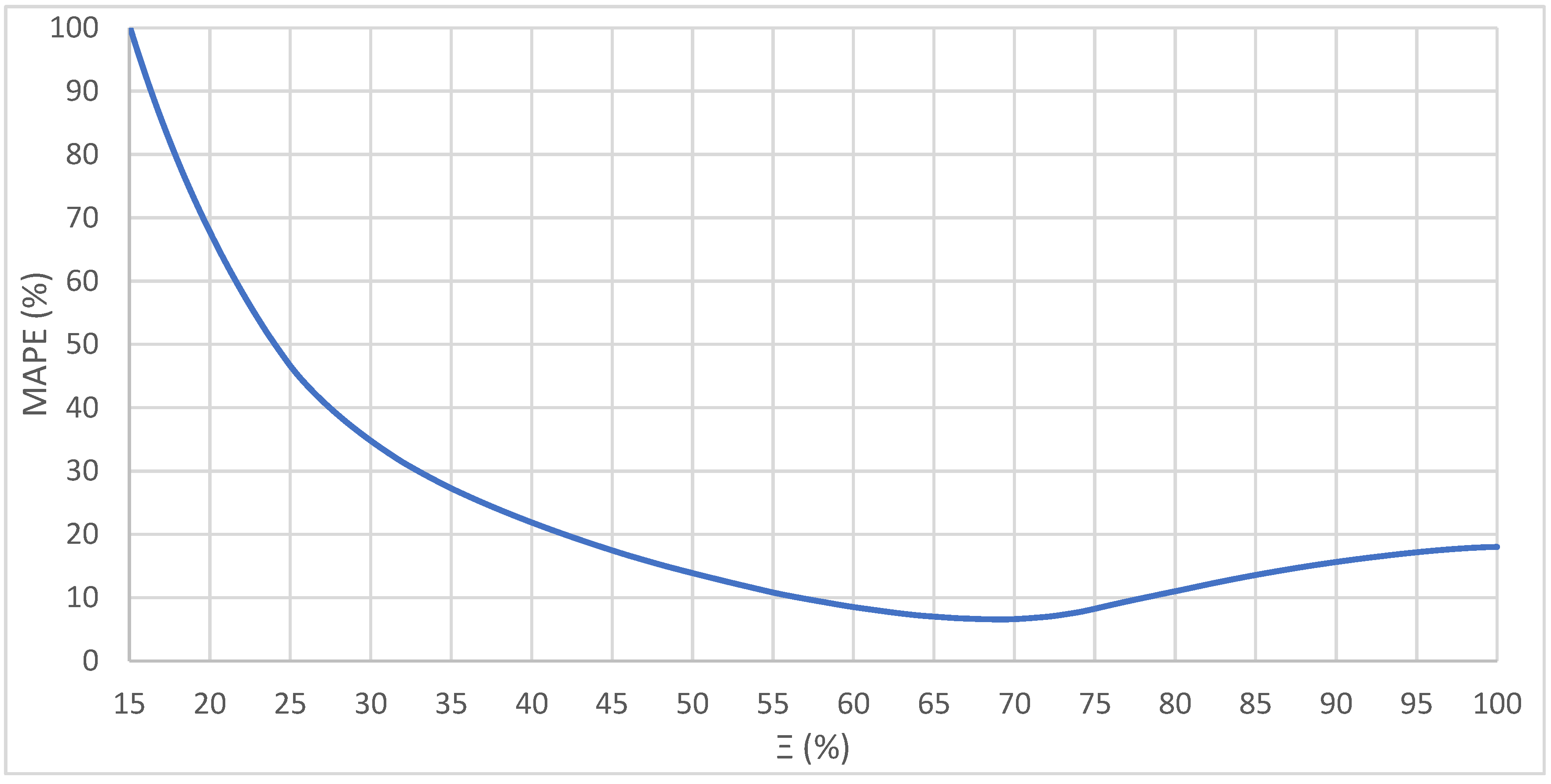
To find the most representative dimensionless fill height for the current Archimedes screw installations (Table 2), Equation (16) was used to compute all η values for the full range of dimensionless fill heights (Ξ). Then a numerical experiment was performed to estimate the overall diameter of the Archimedes screw hydro powerplant installations that are represented in Table 2 by using Equation (16). Technically, the highest agreement of the studied cases with the equation results where there is the minimum difference between the estimations and the actual observations. As shown in Figure 4, the minimum relative difference of MAPE = 2.31% occurs when Ξ = 69%, with a resulting value of η of 1.61. Therefore, this η value was used for the rest of the investigation.
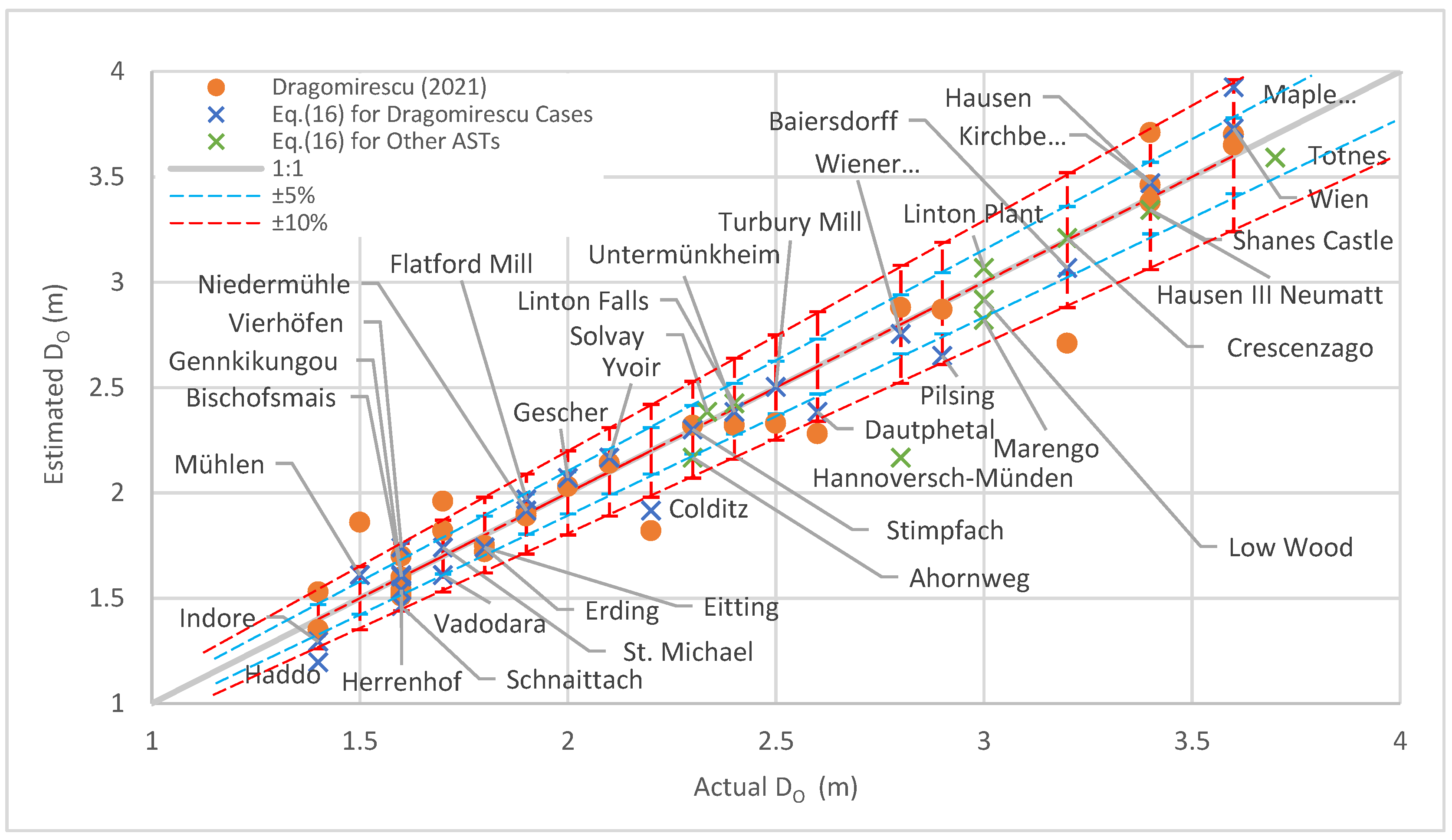
Figure 5 shows the outer diameter for each plant in Table 2 compared to the corresponding outer diameter predicted using Equation (16) with η = 1.61. The evaluation of the proposed analytical equation indicates a reasonable accuracy for the developed equation by a correlation high as high as R = 91.80% and a relative difference as low as MAPE = 6.58% on average. In these results, the point with highest relative difference is the Hannoversch Münden multi-ASG hydropower plant which has a unique design allowing 0° to 28° adjustable inclination angle for operation with variable tailwater levels: it is possible that the data published for this plant is not as representative of operation in conventional conditions.
Figure 5 also compares the accuracy of predictions using the Dragomirescu method [17] with Equation (16) results. According to this figure, both methods indicate a good agreement for these Archimedes screw designs. For Dragomirescu’s specific cases and method, analysis the evaluation criteria indicate a high correlation (R = 96.96%) and low relative difference (MAPE = 5.72%) for this method. For the same cases, Equation (16) produced a higher correlation (R = 98.63%) and lower relative difference (MPAE = 4.54%) than the Dragomirescu method results.
In summary, the results of both methods are arguably good given the assumptions and small number of variables used in both methods. However, considering the analytical nature of Equation (16), the slightly better performance in term of some evaluation criteria, as well as its significant ease of use may make Equation (16) more practical. Equation (16) is developed based on a strong theorical basis that makes it a general equation. Moreover, evaluation of Equation (16) with a wide range of different cases indicates a reasonable accuracy. Finally, using the Dragomirescu method requires predefining the number of blades (N) and length (L) or the inclination angle (β) of screw even for initial estimations while Equation (16) may be used without requiring these variables as outlined below.
4. Analytical Method for Designing Archimedes Screws
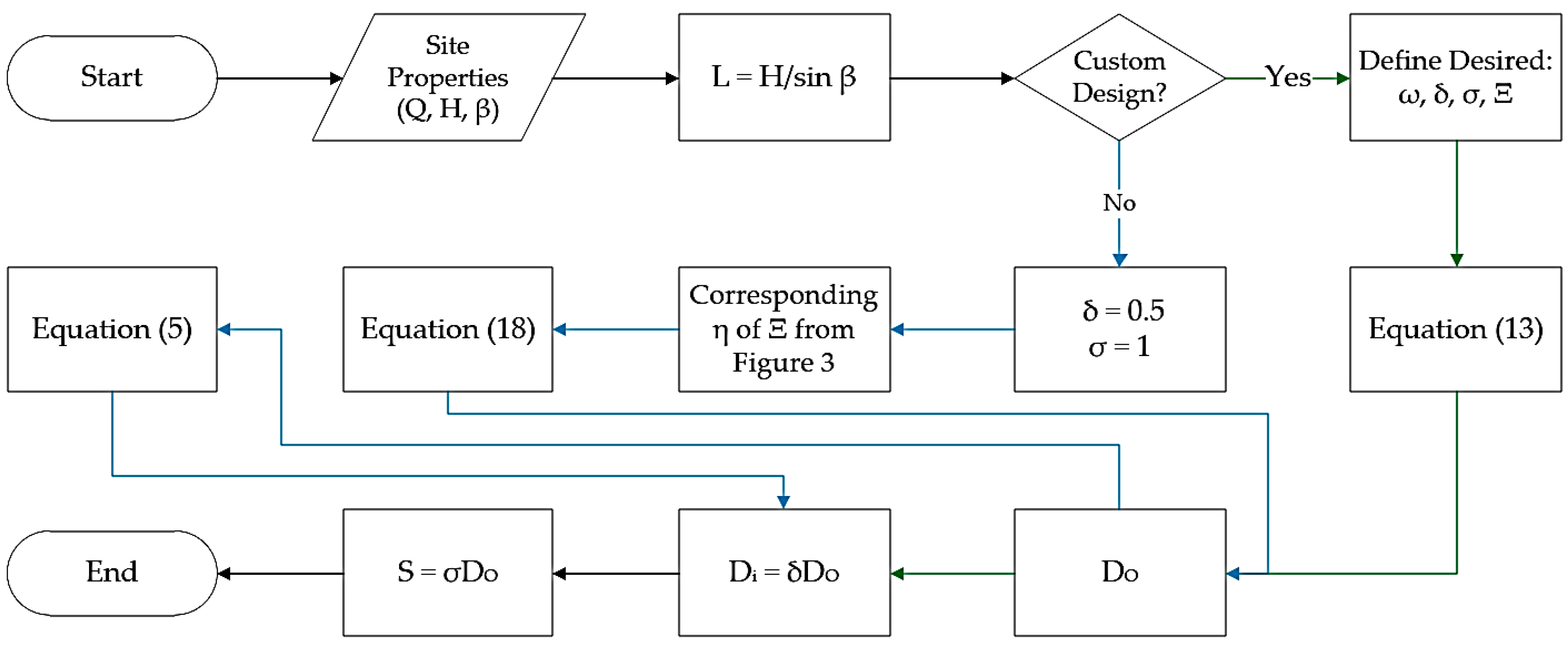
This section proposes a rapid and simple method to estimate the design properties of Archimedes screw generators based on the analytical equations that are proposed in this study. The step-by-step design process of the Archimedes screw is:
- (1)
- (2)
- Use Equation (3) to determine the Archimedes screw’s length.
- (3)
- Use Equation (11) to determinate the overall (outer) diameter DO of the Archimedes screw based on the desired ω, δ, σ and Ξ values. Or,Use Equation (16) to design Archimedes screw similar to the current installed ASGs in hydropower plants (δ = 0.5, σ = 1, Ξ = 69%, η ≈ 1.61 and ψ = 3/7). For example, for Q = 9 m3/s using Equation (16) results . Comparison of the calculated DO with Table 2. indicates that this is a very close outer diameter to the Künzelsau hydropower plant Archimedes screw ( = 4.1 m) with is designed for almost the same flow rate. Or, for Q = 1 m3/s, Equation (18) gives which is almost the same as the average of Bischofsmais, Mühlen and Vadodara ASTs’ outer diameters (1.6 m, 1.5 m and 1.7 m respectively).
- (4)
- Determinate the inner diameter () and screw pitch (S) based on the estimated ( using the following equations:
This method is summarized in the represented flow chart in Figure 6.
5. Conclusions
This study developed an analytical method to produce a rapid initial estimate of the geometry of an Archimedes screw power plant. Analytical equations were developed based on mathematical, physical and hydraulic facts from the literature. Finally, a general analytical equation is proposed to estimate the overall diameter of the ASG, and a method is proposed to estimate the other design properties of the geometry of the Archimedes screws.
The developed analytical equation has been evaluated by 48 industrial Archimedes screws designed by different manufacturers and currently installed and operating in hydropower plants. For this process, the values of parameters were chosen based on the accepted, proved, reported or observed common aspects of Archimedes screws (δ = 0.5, σ = 1, Ξ = 69% and = 3/7). This process also led to simplifying the general analytical equation (Equation (12)) into a much simpler form, resulting in a considerably easier and faster to use equation (Equation (16)) that could be used to design Archimedes screw turbines in a similar basis of current Archimedes screw installations in hydro powerplants.
The evaluation of the proposed analytical equation indicates a reasonable accuracy for the developed equation with a correlation as high as 91.80% and a MAPE as low as 6.61%.
Moreover, results using this equation were compared with Dragomirescu’s method results. Both methods are arguably good given the assumptions and small number of variables used in both methods. However, considering the slightly better performance in terms of the evaluation criteria besides the single-equation nature of Equation (16) as well as its significant ease of use, it seems that Equation (16) is more practical. The strong theoretical basis of Equation (16) results in a general and potentially more reliable method. Moreover, evaluation of Equation (16) with a wide range of different cases indicates a reasonable accuracy. Equation (16) does not require to predefining of the number of blades (N) and length (L) or the inclination angle (β) of screw for initial estimations, which makes it easier to use for initial estimates.
The proposed analytical equation not only showed a reasonable accuracy based on the evaluations but also simplifies and could eliminate several design steps and loops and accelerate the design of Archimedes screws.
Author Contributions
Conceptualization, A.Y. and W.D.L.; methodology, A.Y. and W.D.L.; software, A.Y.; validation, A.Y. and W.D.L.; formal analysis, A.Y. and W.D.L.; investigation, A.Y. and W.D.L.; resources, A.Y.; data curation, A.Y.; writing—original draft preparation, A.Y.; writing—review and editing, A.Y. and W.D.L.; visualization, A.Y.; supervision, W.D.L.; project administration, W.D.L.; funding acquisition, W.D.L. All authors have read and agreed to the published version of the manuscript.
Funding
This work is part of a larger long-term research program that has been financially supported by the Natural Science and Engineering Research Council (NSERC) of Canada, Collaborative Research and Development (CRD) program (grant CRDPJ 513923-17) and Greenbug Energy Inc. (Delhi, Ontario, Canada).
Institutional Review Board Statement
Not applicable.
Informed Consent Statement
Not applicable.
Data Availability Statement
Not applicable.
Conflicts of Interest
The authors declare no conflict of interest.
Nomenclature
The following symbols are used in this paper:
| Effective cross-sectional area at the screw’s inlet | (m2) | |
| Maximum cross-sectional water area at the screw’s inlet | (m2) | |
| The outer diameter’s cross-sectional area | (m2) | |
| Coefficient of dimensionless flow rate | (-) | |
| Coefficient of dimensionless area constant | (-) | |
| Coefficient of dimensionless rotation speed constant | (-) | |
| The inner diameter of the Archimedes screw | (m) | |
| The outer diameter of the Archimedes screw | (m) | |
| The estimated value | ||
| The average of the estimations | ||
| Fill height of water in a bucket of screw | (-) | |
| Upper (inlet) water level of the screw | (m) | |
| Lower (outlet) water level of the screw | (m) | |
| The available head | (m) | |
| Gap width (The gap between the trough and screw) | (m) | |
| T total length of the screw | (m) | |
| The mean absolute percentage error | (%) | |
| n | The number of data points in the dataset | |
| Number of helical planed surfaces | (-) | |
| The observed value | ||
| The average of the observed data | ||
| PE | The percentage (percent) error | (%) |
| Total flow rate passing through the screw | (m3/s) | |
| The maximum flow rate that could pass through a screw when and | (m3/s) | |
| The volumetric flow rate that passes through the cross-sectional area of at the speed of . | (m3/s) | |
| r | Radios | (m) |
| R | Pearson correlation | (%) |
| Pitch of the screw (Distance along the screw axis for one complete helical plane turn) | (m) | |
| Axial transport velocity | (m/s) | |
| y | The cross section fill height | (rad) |
| The free surface elevations at the upstream | (m) | |
| ZL | The free surface elevations at the downstream | (m) |
| Thinclination angle of the screw | (rad) | |
| The screw’s pitch to outer diameter ratio ( | (-) | |
| The constant accounting for screw geometry, rotation speed and fill level in the power function form of the diameter equation | (s3/7m−2/7) | |
| θ | Angle of sector | (rad) |
| The screw’s inner to outer diameter ratio () | (-) | |
| The dimensionless inlet depth of the screw | (-) | |
| The value of power in the power function form of diameter equation | (-) | |
| ω | The rotation speed of the screw | (rad/s) |
| The maximum rotation speed of the screw (Muysken limit) | (rad/s) | |
| Subscripts | ||
| i | inner | |
| min | minimum | |
| Max | Maximum | |
| O | Outer |
References
- Muller, G.; Senior, J. Simplified theory of Archimedean screws. J. Hydraul. Res. 2009, 47, 666–669. [Google Scholar] [CrossRef]
- Kibel, P. Fish Monitoring and Live Fish Trials. Archimedes Screw Turbine, River Dart. Phase 1 Report: Live Fish Trials, Smolts, Leading Edge Assessment, Disorientation Study, Outflow Monitoring; Fishtek Consulting Ltd.: Moretonhampstead, UK, 2007. [Google Scholar]
- Boys, C.A.; Pflugrath, B.D.; Mueller, M.; Pander, J.; Deng, Z.; Geist, J. Physical and hydraulic forces experienced by fish passing through three different low-head hydropower turbines. Mar. Freshw. Res. 2018, 69, 1934–1944. [Google Scholar] [CrossRef]
- McNabb, C.D.; Liston, C.R.; Borthwick, S.M. Borthwick. Passage of Juvenile Chinook Salmon and other Fish Species through Archimedes Lifts and a Hidrostal Pump at Red Bluff, California. Trans. Am. Fish. Soc. 2003, 132, 326–334. [Google Scholar] [CrossRef]
- Kibel, P.; Pike, R.; Coe, T. Archimedes Screw Turbine Fisheries Assessment. Phase II: Eels and Kelts; Publisher: Moretonhampstead, UK, 2008. [Google Scholar]
- Kibel, P.; Pike, R.; Coe, T. The Archimedes Screw Turbine: Assessment of Three Leading Edge Profiles; Publisher: Moretonhampstead, UK, 2009. [Google Scholar]
- United Kingdom Environment Agency. Hydropower Good Practice Guidelines Screening requirements. J. Hydraul. Res. 2012, 4, 1–16. [Google Scholar]
- Piper, A.T.; Rosewarne, P.J.; Wright, R.M.; Kemp, P.S. The impact of an Archimedes screw hydropower turbine on fish migration in a lowland river. Ecol. Eng. 2018, 118, 31–42. [Google Scholar] [CrossRef]
- Pauwels, I.S.; Baeyens, R.; Toming, G.; Schneider, M.; Buysse, D.; Coeck, J.; Tuhtan, J. Multi-species assessment of injury, mortality, and physical conditions during downstream passage through a large archimedes hydrodynamic screw (Albert canal, Belgium). Sustainability 2020, 12, 8722. [Google Scholar] [CrossRef]
- Lashofer, A.; Hawle, W.; Pelikan, B. State of technology and design guidelines for the Archimedes screw turbine. In Proceedings of the Hydro 2012—Innovative Approaches to Global Challenges, online, 1–8 October 2012; Available online: https://bit.ly/3pC7Vah (accessed on 17 November 2021).
- VANDEZANDE BVBA. Lock of Hasselt—Hybrid Hydropower Screw/Screw Pump. Youtube, 5 Jul. 2018. Available online: https://youtu.be/FUlYjkzAIs8 (accessed on 8 August 2021).
- Simmons, S. A Computional Fluid Dynamic Analysis of Archimedes Screw Generators. Master’s Thesis, University of Guelph, Guelph, ON, Canada, 2018. [Google Scholar]
- Simmons, S.C.; Lubitz, W.D. Analysis of internal fluid motion in an Archimedes screw using computational fluid mechanics. J. Hydraul. Res. 2020, 2020, 1–15. [Google Scholar] [CrossRef]
- Shahverdi, K.; Loni, R.; Maestre, J.; Najafi, G. CFD numerical simulation of Archimedes screw turbine with power output analysis. Ocean Eng. 2021, 231, 108718. [Google Scholar] [CrossRef]
- Shahverdi, K.; Loni, R.; Ghobadian, B.; Gohari, S.; Marofi, S.; Bellos, E. Numerical Optimization Study of Archimedes Screw Turbine (AST): A case study. Renew. Energy 2020, 145, 2130–2143. [Google Scholar] [CrossRef]
- Shahverdi, K. Modeling for prediction of design parameters for micro-hydro Archimedean screw turbines. Sustain. Energy Technol. Assess. 2021, 47, 101554. [Google Scholar] [CrossRef]
- Dragomirescu, A. Design considerations for an Archimedean screw hydro turbine. IOP Conf. Ser. Earth Environ. Sci. 2021, 664, 12034. [Google Scholar] [CrossRef]
- YoosefDoost, A.; Lubitz, W. Archimedes screw turbines: A sustainable development solution for green and renewable energy generation—A review of potential and design procedures. Sustainability 2020, 12, 7352. [Google Scholar] [CrossRef]
- Nuernbergk, D.M.; Rorres, C. Analytical Model for Water Inflow of an Archimedes Screw Used in Hydropower Generation. J. Hydraul. Eng. 2013, 139, 213–220. [Google Scholar] [CrossRef]
- Brada, K.; Radlik, K.-A. Wasserkraftschnecke: Eigenschaften und Verwendung. In Heat Exchange and Renewable Energy Sources International Symposium; Politechnika Szczecinska: Szczecin, Poland, 1996; pp. 43–52. [Google Scholar]
- Aigner, D. Current Research in Hydraulic Engineering 1993–2008; Institut für Wasserbau und Technisch Hydromechanik der TU. Association: Dresden, Germany, 2008. [Google Scholar]
- Schmalz, W. Studies on fish migration and control of possible fish loss caused by the hydrodynamic screw and hydropower plant. In Fischo—Kologische und Limnol. Untersuchungsstelle Sudthurign, Rep.; Thüringer Landesanstalt für Umwelt und Geol: Jena, Germany, 2010. [Google Scholar] [CrossRef]
- Lashofer, A.; Kaltenberger, F.; Pelikan, B. Does the archimedean screw turbine stand the test? (Wie gut bewährt sich die Wasserkraftschnecke in der Praxis?). WasserWirtschaft 2011, 101, 76–81. [Google Scholar] [CrossRef]
- Nuernbergk, D.M. Wasserkraftschnecken—Berechnung und Optimaler Entwurf von Archimedischen Schnecken als Wasserkraftmaschine (Hydro-power Screws—Calculation and Design of Archimedes Screws), 2nd ed.; Verlag Moritz Schäfer: Detmold, Germany, 2020. [Google Scholar]
- Rehart Power. Rehart Power 2020 Referenzen. Available online: https://web.archive.org/web/20211024035002/https://www.rehart-power.de/referenzen/wasserkraftanlagen-typ-sh/hausen-sh.html (accessed on 23 October 2021).
- Simmons, S.; Lubitz, W. Archimedes screw generators for sustainable energy development. In Proceedings of the 2017 IEEE Canada International Humanitarian Technology Conference (IHTC), Toronto, ON, Canada, 21–22 July 2017; pp. 144–148. [Google Scholar] [CrossRef]
- Rorres, C. The Turn of the Screw: Optimal Design of an Archimedes Screw. J. Hydraul. Eng. 2000, 126, 72–80. [Google Scholar] [CrossRef] [Green Version]
- YoosefDoost, A.; Lubitz, W.D. Development of an Equation for the Volume of Flow Passing through an Archimedes Screw Turbine. In Sustaining Tomorrow; Ting, D.S.-K., Vasel-Be-Hagh, A., Eds.; Springer: Cham, Switzerland, 2021; pp. 17–37. [Google Scholar]
- Lubitz, W.D.; Lyons, M.; Simmons, S. Performance Model of Archimedes Screw Hydro Turbines with Variable Fill Level. J. Hydraul. Eng. 2014, 140, 04014050. [Google Scholar] [CrossRef]
- Muysken, J. Calculation of the Effectiveness of the Auger. De Ingenieur 1932, 21, 77–91. [Google Scholar]
- Nagel, G. Archimedean Screw Pump Handbook; RITZ-Pumpenfabrik OHG: Schwabisch Gmund, Germany, 1968. [Google Scholar]
- Rodgers, J.L.; Nicewander, W.A. Thirteen Ways to Look at the Correlation Coefficient. Am. Stat. 1988, 42, 59–66. [Google Scholar] [CrossRef]
- YoosefDoost, A.; YoosefDoost, I.; Asghari, H.; Sadeghian, M.S. Comparison of HadCM3, CSIRO Mk3 and GFDL CM2. 1 in Prediction the Climate Change in Taleghan River Basin. Am. J. Civ. Eng. Arch. 2018, 6, 93–100. [Google Scholar] [CrossRef] [Green Version]
- Adler, J.; Parmryd, I. Quantifying colocalization by correlation: The pearson correlation coefficient is superior to the Mander’s overlap coefficient. Cytom. Part A 2010, 77A, 733–742. [Google Scholar] [CrossRef]
- Kim, S.; Kim, H. A new metric of absolute percentage error for intermittent demand forecasts. Int. J. Forecast. 2016, 32, 669–679. [Google Scholar] [CrossRef]
- Hanke, J.E.; Wichern, D. Business Forecasting, 9th ed.; Prentice Hall: London, UK, 2009. [Google Scholar]
- Bowerman, B.L.; O’Connell, R.T.; Koehler, A.B. Forecasting, Time Series, and Regression: An Applied Approach, 4th ed.; Thomson Brooks/Cole: Belmont, CA, USA, 2005. [Google Scholar]
- Ingenieurbüro Lashofer. Hydropower Screws in Europe. Google Maps. Available online: Efort.info/AST-Map (accessed on 3 August 2021).
- SinFin. Solvay Industrial Plant. SinFin Energy. 2019. Available online: http://www.sinfinenergy.com/en/projects/solvay/ (accessed on 8 July 2020).
- Rose, R. Linton Falls and Low Wood Hydropower Schemes. River Coast., UK Water Projects 2011, 197–202, 2011, [Online]. Available online: https://waterprojectsonline.com/ (accessed on 26 October 2021).
- Rehart Power. Hannoversch Münden CS. Available online: https://web.archive.org/web/20211027000737/https://www.rehart-power.de/en/reference-projects/hydropower-screw-type-cs/hannoversch-muenden-cs.html (accessed on 26 October 2021).
- Landustrie. Linton Lock. Landustrie Sneek BV. 2017. Available online: https://web.archive.org/web/20210804020631/https://www.landustrie.nl/en/products/hydropower/projects/linton-lock.html (accessed on 29 July 2020).
- Fergnani, N. Hydroelectric Plants Energy Efficiency. Hydrosmart Srl. 2020. Available online: https://www.hydrosmart.it/energia-rinnovabile (accessed on 2 August 2020).
- Sto98. Marengo Hydropower Plant-Goito [Centrale Idroelettrica Marengo-Goito]. YouTube, Feb. 19, 2015. Available online: https://youtu.be/19px1EKa--4 (accessed on 19 July 2020).
- RenewablesFirst. Radyr Weir Hydro Turbines. Renewables First, Oct. 28, 2015. Available online: https://web.archive.org/web/20210804003006/https://www.renewablesfirst.co.uk/project-blog/radyr-weir-hydro-scheme/ (accessed on 5 July 2020).
- Landustrie Sneek BV. Totnes Weir (UK). Landustrie Worldwide Water Technology, Nov. 18, 2015. Available online: https://web.archive.org/web/20210803231005/https://www.landustrie.nl/fileadmin/user_upload/Totnes_Times_November_2015.pdf (accessed on 3 August 2021).
- Gratton, P.; Meadows, T.; Brook, T. Gunthorpe Weir Hydropower Scheme: Fisheries and Geomorphology Assessment. The Mill, Stroud, UK, 2019. [Online]. Available online: http://web.archive.org/web/20210804003408/https://consult.environment-agency.gov.uk/psc/canal-river-trust-27520-29519/supporting_documents/Fisheries and Geomorphology Assessment Gunthorpe Weir MD0280064047.pdf (accessed on 9 September 2021).
- Vandezande BVBA. Vandezande Specialist in Mechanics. Vandezande.com, Zeepziederijstraat, Brugge, Belgium, [Online]. Available online: https://web.archive.org/web/20210809031945/https://www.vandezande.com/sites/default/files/vandezande-folder%202017-eng%20LR04.pdf (accessed on 9 August 2021).
- Vandezande Diksmuide. Hydropower Screws Höllthal. Vandezande. Available online: https://web.archive.org/web/20210809061648/https://www.vandezande.com/en/projects/hydropower-screws-höllthal (accessed on 9 August 2021).
- Vandezande Diksmuide. PS/WKC Lock Hasselt. Vandezande. Available online: https://web.archive.org/web/20210405220637/https://www.vandezande.com/en/projects/ps-wkc-lock-hasselt (accessed on 9 August 2021).

Figure 2.
Required parameters to define the effective area.

Figure 3.
Comparison of Equation (14) results for and different values.

Figure 4.
Equation (16) results for the whole range of the dimensionless inlet depth of the screw (Ξ) values in comparison with the currently installed AST designs of Table 2.
Figure 4.
Equation (16) results for the whole range of the dimensionless inlet depth of the screw (Ξ) values in comparison with the currently installed AST designs of Table 2.

Figure 5.
Comparison of Equation (16) results with Dragomirescu [17] and the other Archimedes screw installations (Table 2).

Figure 6.
A fast and easy analytical method for designing Archimedes screws.


Table 1.
Required parameters to define Archimedes screws’ geometry and operating variables.
| Parameter | Description | Variable | Description | ||
|---|---|---|---|---|---|
| L | (m) | Total length of the screw | ω | (rad/s) | Rotation speed of screw * |
| DO | (m) | Outer diameter | hu | (m) | Upper (inlet) water level |
| Di | (m) | Inner diameter | hL | (m) | Lower (outlet) water level |
| S | (m) | Screw’s pitch or period [27] (The distance along the screw axis for one complete helical plane turn) | Q | (m3/s) | Volumetric flow rate passing through the screw |
| N | (1) | Number of helical planed surfaces (also called blades, flights or starts [27]) | |||
| β | (rad) | Inclination Angle of the Screw | |||
| Gw | (m) | The gap between the trough and screw. | |||
* Note: In the fixed speed Archimedes screws rotation speed is a constant.
Table 2.
Details of Archimedes screw hydropower plants used for model evaluation.
| ID | Name | DO (m) | H (m) | Q (m3/s) | P (kW) | Note | Ref. |
|---|---|---|---|---|---|---|---|
| 1 | Haddo | 1.4 | 5 | 0.5 | 15.9 | * | [17,25] |
| 2 | Indore | 1.4 | 5.3 | 0.6 | 19 | * | [17,25] |
| 3 | Mühlen | 1.5 | 3 | 1 | 21 | * | [17,25] |
| 4 | Bischofsmais | 1.6 | 3.16 | 1 | 21 | * | [17,25] |
| 5 | Gennkikungou | 1.6 | 1.05 | 0.99 | 7.3 | * | [17,25] |
| 6 | Herrenhof | 1.6 | 2.1 | 0.9 | 13.9 | * | [17,25] |
| 7 | Schnaittach | 1.6 | 1.35 | 0.8 | 7.5 | * | [17,25] |
| 8 | Vierhöfen | 1.6 | 1 | 1.2 | 8 | * | [17,25] |
| 9 | St. Michael | 1.7 | 3.2 | 1.2 | 26.92 | * | [17,25] |
| 10 | Vadodara | 1.7 | 5 | 1 | 33 | * | [17,25] |
| 11 | Eitting | 1.8 | 3.57 | 1.2 | 29 | * | [17,25] |
| 12 | Erding | 1.8 | 1.75 | 1.2 | 13.9 | * | [17,25] |
| 13 | Flatford Mill | 1.9 | 1.1 | 1.6 | 12.6 | * | [17,25] |
| 14 | Niedermühle | 1.9 | 3.17 | 1.5 | 33 | * | [17,25] |
| 15 | Gescher | 2 | 3.45 | 1.8 | 46 | * | [17,25] |
| 16 | Yvoir | 2.1 | 1.8 | 2 | 26 | * | [17,25] |
| 17 | Colditz | 2.2 | 3 | 1.5 | 33 | * | [17,25] |
| 18 | Ahornweg | 2.3 | 1.45 | 2 | 21 | [38] | |
| 19 | Solvay | 2.3 | 2 | 2.5 | 35 | [39] | |
| 20 | Stimpfach | 2.3 | 2.55 | 2.3 | 44 | * | [17,25] |
| 21 | Linton Falls | 2.4 | 2.7 | 2.6 | 50 | [40] | |
| 22 | Untermünkheim | 2.4 | 1.8 | 2.5 | 31 | * | [17,25] |
| 23 | Turbury Mill | 2.5 | 2.1 | 2.8 | 43 | * | [17,25] |
| 24 | Dautphetal | 2.6 | 2.55 | 2.5 | 45.8 | * | [17,25] |
| 25 | Hannoversch-Münden | 2.8 | 2.6 | 2 | 35.455 | [41] | |
| 26 | Wiener Neustadt | 2.8 | 4.05 | 3.5 | 98 | * | [17,25] |
| 27 | Pilsing | 2.9 | 3.6 | 3.2 | 8 | * | [17,25] |
| 28 | Linton Plant | 3 | 3.2 | 4.5 | 110 | ☆ | [18,42] |
| 29 | Low Wood | 3 | 7.2 | 4 | 200 | [40] | |
| 30 | Marengo | 3 | 1.6 | 3.7 | 51 | [43,44] | |
| 31 | Baiersdorff | 3.2 | 1.5 | 4.5 | 48.1 | * | [17,25] |
| 32 | Crescenzago | 3.2 | 2.1 | 5 | 75 | [38] | |
| 33 | Hausen | 3.4 | 5.8 | 6 | 250 | * | [17,25] |
| 34 | Hausen III Neumatt | 3.4 | 5.8 | 5.5 | 235 | [38] | |
| 35 | Kirchberg | 3.4 | 2.97 | 6 | 130 | * | [17,25] |
| 36 | Shanes Castle | 3.4 | 5 | 5.5 | 192 | * | [17,25] |
| 37 | Radyr | 3.5 | 3.5 | 11 | 200 | [45] | |
| 38 | Maple Durham | 3.6 | 1.73 | 8 | 99 | * | [17,25] |
| 39 | Wien | 3.6 | 1.7 | 7.1 | 84 | * | [17,25] |
| 40 | Totnes | 3.7 | 3.45 | 6.5 | 160 | [46] | |
| 41 | Künzelsau | 4.1 | 1.72 | 8.95 | 132 | [38] | |
| 42 | Plana | 4.1 | 3.5 | 8.73 | 220 | [38] | |
| 43 | Gunthorpe Weir | 4.3 | 2.03 | 14.15 | 165 | [47] | |
| 44 | Ham | 4.3 | 10 | 5 | 360 | [38,48] | |
| 45 | Höllthal | 4.3 | 2.22 | 10.5 | 220 | [38,49] | |
| 46 | Olen | 4.3 | 10 | 5 | 360 | [38,48] | |
| 47 | Hasselt | 5 | 10 | 5 | 400 | [11,50] | |
| 48 | Widdington Plant | 5 | 3 | 14.5 | 335 | ☆ | [18,42] |
Notes: * Used in Dragomirescu [17]; ☆. Two different Archimedes screws installed in Linton Lock hydropower plant.
Publisher’s Note: MDPI stays neutral with regard to jurisdictional claims in published maps and institutional affiliations. |
© 2021 by the authors. Licensee MDPI, Basel, Switzerland. This article is an open access article distributed under the terms and conditions of the Creative Commons Attribution (CC BY) license (https://creativecommons.org/licenses/by/4.0/).
Share and Cite
MDPI and ACS Style
YoosefDoost, A.; Lubitz, W.D. Archimedes Screw Design: An Analytical Model for Rapid Estimation of Archimedes Screw Geometry. Energies 2021, 14, 7812. https://doi.org/10.3390/en14227812
AMA Style
YoosefDoost A, Lubitz WD. Archimedes Screw Design: An Analytical Model for Rapid Estimation of Archimedes Screw Geometry. Energies. 2021; 14(22):7812. https://doi.org/10.3390/en14227812
Chicago/Turabian StyleYoosefDoost, Arash, and William David Lubitz. 2021. "Archimedes Screw Design: An Analytical Model for Rapid Estimation of Archimedes Screw Geometry" Energies 14, no. 22: 7812. https://doi.org/10.3390/en14227812
Note that from the first issue of 2016, this journal uses article numbers instead of page numbers. See further details here.