
Analysis of AC/DC/DC Converter Modules for Direct Current Fast-Charging Applications
by
 , , and
Szymon Piasecki
1 ,
,
Jaroslaw Zaleski
2,
Marek Jasinski
1,*,
Serafin Bachman
1 and
Marek Turzyński
3 1
Institute of Control and Industrial Electronics, Warsaw University of Technology, Koszykowa 75, 00-662 Warsaw, Poland
2
Twerd Power Electronics Ltd., R&D Department, Aleksandrowska 28-30, 87-100 Torun, Poland
3
Faculty of Electrical and Control Engineering, Gdansk University of Technology, 80-233 Gdansk, Poland
*
Author to whom correspondence should be addressed.
Energies 2021, 14(19), 6369; https://doi.org/10.3390/en14196369
Submission received: 6 September 2021
/
Revised: 24 September 2021
/
Accepted: 1 October 2021
/
Published: 5 October 2021
(This article belongs to the Special Issue New Topologies of Voltage Source Converters and Current Source Converters for Integration of Fast EV Charging Stations within Smart Grids)
Abstract
:The paper is a comprehensive laboratory comparison study of two galvanic isolated solution off-board battery chargers: (1) Si-based cost-effective case, and (2) SiC-bidirectional ready for vehicle to grid concept case. All circuits are modular, and in both cases the DC/DC converter can be replaced according to the end user requirements (the coupled transformer remains the same and is constructed based on 12xC100 cores to avoid additional choke). In the case of single active bridge, an active RCD snubber is proposed to protect against overvoltage above 1kV in the DC_2 circuit. The dual active bridge is equipped with soft-star modulation using a zero vector to reduce in-rush current in case of no-load operation, while the AC/DC grid connected converter remains bidirectional to assure the highest power quality at the point of common coupling. All tests were made with real second-used batteries, which improves environmental, economic and technical feasibility of such systems for prosumers. The total efficiency of both AC/DC/DC converters (>97% in SiC and >94% in Si versions) was investigated in the same laboratory conditions.
1. Introduction
The changes taking place in the electric vehicle market go beyond the traditional automotive market and significantly affect the operation of the entire electrical grid—mainly due to the demand for energy and its availability [1,2], but also because of the quality of the processed energy [2,3]. Electro-mobility is going to be an important part of the modern energy transition, especially in the transportation sector. According to Bloomberg, the increased electricity demand from EVs in the year 2050 would be between 5500 TWh and 8500 TWh (depending on the economic transition or net zero scenario, respectively). Emerging new solutions, materials and technologies try to respond to the needs of the changing market in a satisfactory manner. However, the implementation of new technologies on a large scale carries many challenges and problems. One of the barriers to the development of electromobility is the lack of charging infrastructure, which effectively hinders the popularization of ecological transport [1,2,3,4].
The energy chain from the source to the wheels in an electric vehicle is as follows: electrical AC power grid voltage is converted by the switching mode power electronic converters (usually AC/DC/DC) to DC voltage, which is then equally distributed to all battery cells by the battery management system (BMS) or equalizers [5], where several equalizers utilizing buck-boost and switched-capacitor converters are used. The aim of BMS is to equalize voltages in the connected battery packs. Then, the voltage is passed from the battery through DC/AC converters to the electrical machine and wheels. It is noteworthy that the bidirectional power flow is mandatory here. In the case of regenerative breaking in both hybrid [6], and electrical [7] vehicles, the power electronics converter and its control play an important role. The optimized control and topology allow to reduce the current and voltage THD to c. 1%. Moreover, the converters in EV drives can be potentially used to charge the battery if needed.
There are several possible ways to produce the energy for supplying electrical power systems. The most common way involves the use of nuclear or fossil fuel plants. However, renewable energy sources like photovoltaics, wind, hydro or bio power plants are recently gaining more and more interest at the energy market. Thanks to the distributed energy sources, the prosumers would harvest the energy and use it to charge their own energy storages. In particular, this energy could be used for charging the electrical vehicle battery. The lifetime of the battery strongly depends on the quality of charging and the temperature of the battery [6,7]. On the other hand, from the user perspective, the time of charging should be as short as possible. Therefore, to optimize both the charging time, and the battery lifetime and temperature, sophisticated power electronics converters need to be used in cooperation with efficient BMS systems and battery aging and production quality control [8]. The subject is wide and for consistency, a novel power electronics converter for only EV DC fast charging is considered in this paper (see Figure 1).
Safe and fast charging of an electric vehicle battery with a minimized impact on its life is a complex process that requires the use of appropriate tools—mainly chargers, but also communication and management systems [9,10]. In recent times, the automotive industry and scientists are trying to find the optimal topology for on board and off board charging systems (OBC and OffBC, respectively) [1,2,3,4]. The wireless charging and battery swapping is also a convenient solution to provide energy to EVs. However, these methods go beyond the scope of this paper. Wired charging is based on three technically available solutions [11,12]:
- (1)
- slow charging, low power (up to 4 kW) AC single-phase (during long term stops), available solutions in both OBC and OffBC versions;
- (2)
- fast charging, medium power (up to 25 kW) AC three-phase, available for OffBC and OBC solutions using machine winding in idling drive;
- (3)
- fast charging, high power DC (up to 900 kW planned), available for OffBC solutions directly connected to the battery through BMS.
In this paper, the OffBC topology is analyzed. The subject is interdisciplinary [2,3,4,5,11,12] and complicated, as the system consists of power electronic converters, sophisticated microcontrollers, communications, and monitoring systems. The very interdisciplinary problems that should be solved in the charging process are the reason why the development in this subject is relatively slow [5,6]. Even though the electrical vehicles are known since the beginning of the XX century, it seems that the second decade in the XXI century is providing a new opportunity for their mass production. From the nature of mass production, the universality, simplicity, modularity, reliability, and costs are the most important coefficients.
The functionality and properties of electric vehicle charging systems are described in norms and standards. The most important are IEC 61851 [13,14], IEC 60364 (TC64) [15], and IEC 61439-7 (TC121B) [16]. Charging interfaces are defined by IEC 61851, (SAE) J1772 [17], and IEC 61980 (TC69) [18]. An important standard is “Charge the Move (ChAdeMO)” extended by China Electricity Council + ChAdeMO (ChaoJi up to 900 kW with 1.5 kV and 0.6 kA). The other standard is the Tesla standard. Currently combined charging systems (CCS) supported by the CharIn organization are standardized by SAE J1772 in the US and by IEC 61851-23 in the EU (up to 200 kW and 0.2–1 kV) with an update available (400 kW and 1.5–3 kV).
Additional functional guidelines are also specified by charging station operators and installers [19,20,21,22]. Due to the still small number of vehicles, their price is a very important criterion related to the development of charging stations. Based on the performed analysis, the two-stage conversion AC<->DC//DC (bidirectional galvanic isolated AC/DC converters) seems to best meet current and future requirements for charging systems [20,21,22]. However, due to the cost constraint, the unidirectional modular conversion is also attractive (c. 15% cheaper). Hence, in this paper the authors compare in the same laboratory conditions two main topologies which seem the most promising: (1) the Si based single active bridge (SAB)—cost effective with basic features, and (2) the SiC based dual active bridge (DAB), bidirectional and ready for vehicle-to-grid (V2G) concept [23]. Both topologies are of OffBC type (in AC/DC/DC converter), when connected to the real second used EV battery—according to the battery second use (B2U) strategy to protect the natural environment and reduce the overall cost of EVs [24,25]. This detailed investigation clearly shows the pros and cons of both topologies. Theoretical descriptions of SAB and DAB can be found in [26,27,28,29]. It is also worth mentioning about resonant converters, whose resonant circuits allow for switching semiconductor power switches under zero voltage or zero current conditions [30]. Based on the literature review, it can be distinguishable that most of the proposed solutions are derived from unidirectional LLC topology [31,32,33]. In the case of bidirectional resonant converters, most of the considered solutions are based on the LLC approach in combination with DAB topology [34,35].
The bidirectional grid connected converter (GCC) should always be implemented at the point of common coupling (PCC) to ensure the highest quality and when the V2G or vehicle-to-device concept is obligatory to increase the stability of the grid [36] or to make an alternative backup for the household in case of black-out [1]. The operation under distorted grid voltage and high impedance is also required [37,38].
The DC/DC stage should be implemented in unidirectional (cost effective) and bi-directional version (flexible and ready for new standards). In case of a power circuit update, only the DC/DC stage can be replaced, while AC/DC remains the same. Moreover, due to the shortest charging time (the highest power), the convenient solution is direct current fast charging (DCFC), which allows direct connection to the vehicle’s BMS with the battery without power limitation of the onboard charger [1,2,3,4,39,40].
On the other hand, the expansion of the EV charging infrastructure has a significant impact on the electrical grid [1,9,10,11]. Chargers are becoming a permanent element of the energy ecosystem. Their efficiency and the quality of the energy processed with the grid are of increasing importance [1,10]. The most important functionalities of charging systems include compensation of reactive power and higher harmonics at PCC as well as the possibility of bidirectional energy transfer and operation under grid voltage distortion [1,2,3,37,41]. Bidirectional operation of the charger allows using the station in the intelligent energy infrastructure, thus enabling the use of EV batteries as mobile energy storage. With the mass use of electric vehicles in the future, it will provide the opportunity of stabilizing an electrical power grid based mainly on renewable resources [1,2,3,38]. This is the critical functionality of future energy systems with B2U [24,25], which would be a real alternative for expensive energy storages. Power electronics components play a key role in electric vehicle charging systems; therefore, the selection of the appropriate solution is one of the main factors in the development and implementation of these systems. The CCS should be simple, modular and easy to control. Thanks to this, the CCS would be scalable in ranges of power and voltage levels.
In this paper, the brief view of the state of the art in EV charging standards is presented in the Introduction, while Chapter 2 describes selected DCFC topologies with both energy conversion stages. The AC/DC bidirectional converter assures the highest energy quality at the PCC (THDi c. 2%) while the DC/DC converter provides galvanic isolation between the electrical grid and the EV. After comparing features, two-level bidirectional Si and SiC AC-DC converters with Si based SAB and SiC based DAB converters were selected and investigated in simulation and experimental studies. The applied simulation model and the performed analysis are described in Chapter 3. The experimental setup with real EV battery is presented in Chapters 4 and 5, while Chapter 6 provides the discussion of the obtained results and conclusions.
The novelty of this paper is a comprehensive laboratory comparison of two OffBC solutions: (1) an Si-based cost-effective case, and (2) an SiC-bidirectional ready for V2G concept case. All circuits are modular, and in both cases the DC/DC converter can be replaced according to the end user requirements, while the coupled transformer, constructed based on 12xC100 cores to avoid an additional choke, remains the same. In the case of SAB, an active RCD snubber is proposed to protect against overvoltage above 1 kV in the DC_2 circuit. The DAB is equipped with soft-star modulation using a zero vector to reduce in-rush current in case of no-load operation, while the AC/DC grid connected converter remains bidirectional to assure the highest power quality in the PCC. All tests were made with a real battery B2U, which improves environmental, economic and technical feasibility of such systems for prosumers [24,25,42].
2. Direct Current Fast Charging Power Converter Topologies
2.1. Requirements
The power electronics used in the chargers makes it possible to process the energy from the grid and adjust it to the vehicle battery parameters. The main requirements for the converters are high efficiency and high power density. Moreover, the converter should provide galvanic separation between the grid and the EV’s battery, generate low EMI noise, not generate acoustic noise, and, preferably, operate in the frequency range inaudible to human ears. The selection of the appropriate converter topology and the optimization of its operating parameters and the components used are the main factors influencing the development of the final product.
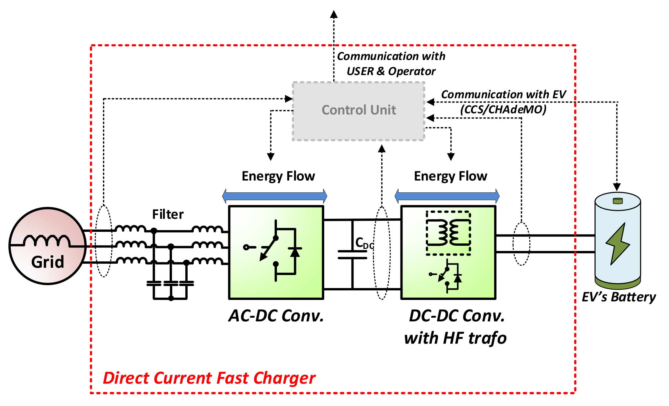
The system of DCFC, generally presented in Figure 1, is composed of AC/DC and DC/DC converters. Such a configuration ensures sufficient dynamics of the charger, precise DC voltage regulation, and a high quality of energy on the grid side. To obtain galvanic separation, the high-frequency DC transformer can be used, as it allows to achieve smaller dimensions of the converter than in the case of classic AC transformers [21,22].
2.2. AC/DC Convertergrid Side
The first stage of the charger is the AC to DC converter, which rectifies three-phase AC voltage to DC voltage. For European gids, it is mainly 3 × 400 V transferred up to 650–900 V DC. Due to the limitations of current harmonics on the grid side and reactive power consumption, active AC/DC rectifiers are preferred as the input stage of the charger. The AC/DC active rectifier ensures bidirectional power flow, accurate DC-link voltage control, higher harmonic reduction, and, if proper control is applied [36,37,41], high immunity to grid voltage disturbances. Moreover, when the power flow from the battery to the grid is considered, additional functionality can be proposed: a grid-forming feature [43].
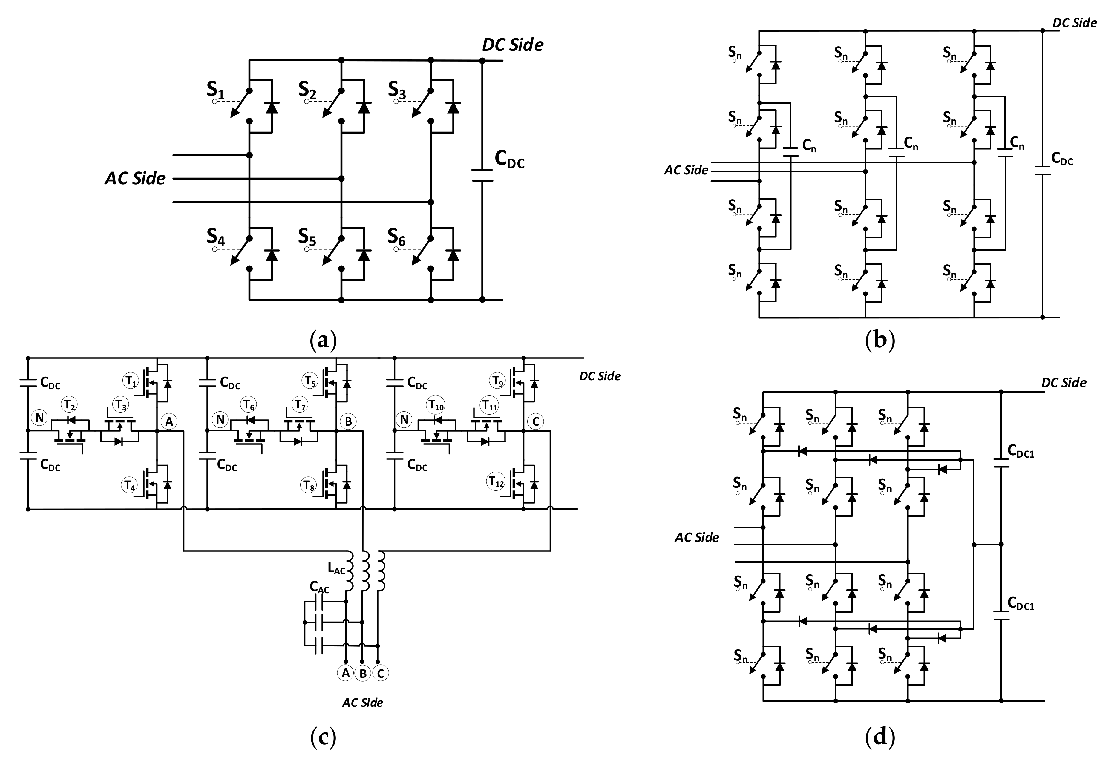
The most popular topologies for active rectifiers for low voltage applications are two-level Voltage Source Converters (VSCs, see Figure 2a) and three-level converters, such as Floating Capacitor Converters (FLCs see Figure 2b), T-type converters (see Figure 2c) and Neutral Point Clamped Converters (NPCs, see Figure 2d). Depending on the topology, the converter makes use of 6 or 12 active switches usually rated for 1200 or 650 V, as presented in Table 1. A transistor with a reverse diode is considered as the active switch. The greater number of active switches means a greater complexity of the control circuit, which must handle a greater number of control and protection signals for the switches.
The AC/DC converter is connected to the grid through the filter consisting of passive elements (inductors and capacitors). The filter limits di/dt on semiconductors, reduces harmonics related to the switching frequency and its multiplications, and separates the converter from the grid. Proper selection of filter parameters offers the possibility of undesired harmonics reduction to fulfil the required power quality standards [44,45,46,47,48]. Passive components also have high influence on the dynamic behavior and properties of the converter itself [45,46,47,48]. Moreover, the cost of filter components, depending on the technology and materials used, is around 20% up to 30% of that of the whole converter system [49]. For an active AC/DC converter, the most popular are LC or LCL filters, but more advanced structures of grid filters, such as an LCL with a tuned trap (LCL+Trap) and LLCL filters, are also introduced [50,51].
The 2-level VSC is the simplest and most mature topology. It utilizes only six active switches, all rated for full DC voltage. In the analyzed case, the 1200 V class transistors may be used. Due to the 2 levels of AC voltage, higher values of grid filters need to be used, as compared to 3-level topologies. On the other hand, thanks to the use of SiC transistors and increasing the switching frequency, the filters can be significantly reduced, thus reducing overall dimensions of the device. The undoubted advantage of this topology is the simplicity of the control circuit, requiring only six control signals, two or three AC current and voltage sensors, and only one DC voltage measurement sensor.
The 3-level converters are more complicated. Their main advantage is reducing dv/dt stresses on the switching devices due to a smaller increment in voltage steps. This causes the reduction of EMC problems at higher voltage values, and allows a smaller rating of semiconductor devices and reduction of filter components on the grid side; additionally, switching losses are reduced. However, the 3-level converters are more complicated and require at least 12 control signals. In the floating capacitor (FLC), a critical matter is to keep capacitor voltages constant. It is an independent process for each phase that takes place when the 0.5 UDC potential is demanded at phase output. Choosing one of available states, depending on the direction of the output current, makes charging and discharging the floating capacitor possible in each phase. This mechanism allows voltage balancing but makes the modulation technique more complicated and time-consuming than in Neutral Point Clamped Converters (NPCs) [52,53]. Basic parameters of the analyzed topologies are presented in Table 1.
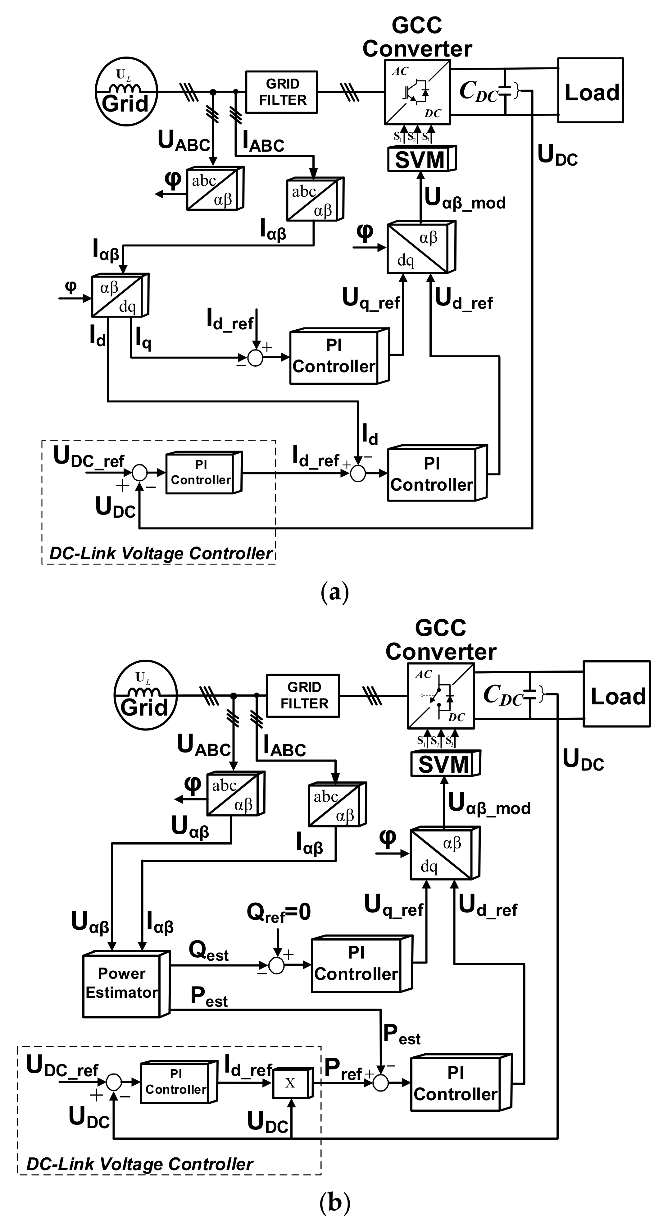
To achieve satisfying DC voltage regulation and dynamic and stable operation during transients, an advanced control strategy needs to be implemented. The two most popular regulation schemes are based on Voltage Oriented Control (VOC, see Figure 3a) and Direct Power Control with Space Vector Modulation (DPC-SVM, see Figure 3b). The VOC method is based on current measurements, their transformation to rotating d-q coordinates, and implementation of PI controllers. The main difference in DPC-SVM is that based on current and voltage measurements, the instantaneous values of active and reactive power are calculated. This approach allows controlling active and reactive power directly, which gives some benefits for reactive power compensation. The control quality is improved when the Space Vector Modulation technique is used [54]. Both methods are sensitive to grid voltage distortions. Therefore, additional structures in the algorithms are often used. More details related to control methods can be found in [55,56,57].
On the basis of a brief analysis of the properties, summarized in Table 2, the two-level converter seems the best solution for the construction of the prototype. All mentioned topologies will consider the problem of selecting semiconductors based on the comparative studies of Si/SiC/GaN power transistors for medium voltages. In order to increase the efficiency and reduce the dimensions of the filter on the grid side, it also seems reasonable to use SiC transistors—although it will increase the price of the system.
2.3. DC//DC Galvanically Isolated Converter Battery Side
The DC/DC converter realizes voltage adjustment between the vehicle’s battery and the input stage of the charger, and voltage regulation on the battery side during the charging process. In electric vehicle charging applications, the following DC/DC converter topologies may be used: flyback converter [58], dual-flyback [59], half-bridge or push–pull [60], and single active bridge (SAB). For bidirectional operation, dual-half-bridge [61] or dual-push–pull [62] and dual active bridge (DAB) [63] or LLC DC-DC circuit [64,65] topologies can also be used. Due to volume limitations, the authors consider only topologies that provide galvanic isolation between DC and AC circuits through a high-frequency DC transformer.
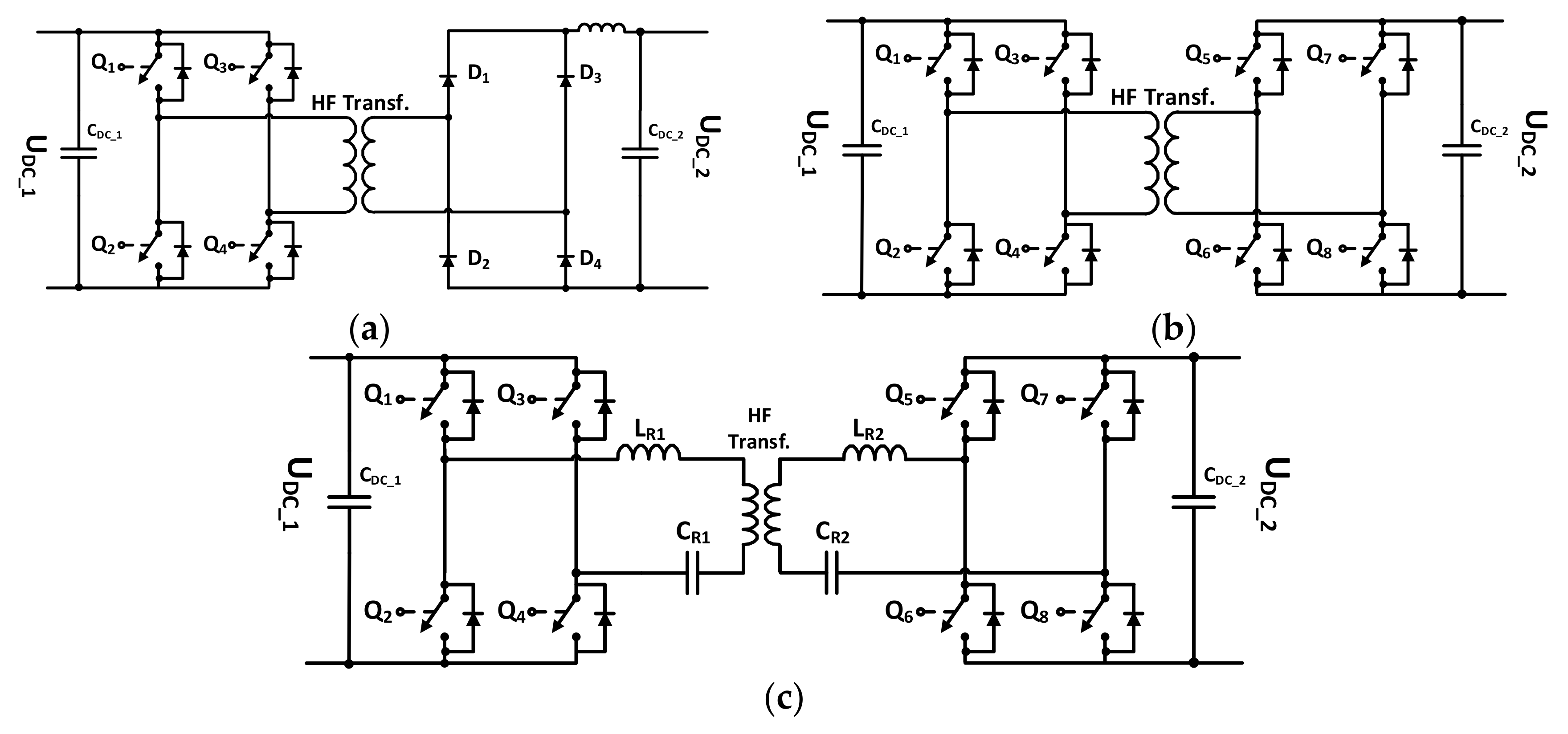
The SAB converter, shown in Figure 4a, consists of an active bridge operating as an inverter, a transformer, and a diode rectifier. The advantage of this system is its simplicity, no need to use additional inductance, no second-side control, and high efficiency and switching frequency. Significant problems of this topology are the lack of control over the secondary side voltage, current overshoot, and high transformer capacitance which causes the transfer of disturbances and voltage overshoots. The critical aspect of this topology is to ensure the lowest possible inductance of the rectifier-transformer connections, which have significant impact on the level of interference and lifetime.
The second topology used in automotive DC to DC conversion systems is an isolated DAB controlled by phase shift. Its topology is presented in Figure 4b. The advantage of this solution over others is bi-directional power flow, isolation of the primary side from the secondary side, the possibility to obtain high switching frequency, high efficiency, simplicity, and soft-switching mode of operation. This solution is particularly beneficial when the application requires a small, light, and efficient device with galvanic isolation. Because of a high level of power density, of more than 10 kW/dm3, this topology is commonly used in automotive, photovoltaic, and other systems [66]. The problems of DAB which require a broader analysis are the optimization of operating parameters for a wide range of output voltages and the operation at low output voltage. A startup procedure is required to limit current pulses at low voltages. As a rule, it is implemented by limiting the width of the transistor control pulses.
In [67], a symmetrical LLC DC-DC topology is proposed. Its block scheme is shown in Figure 4c. Two capacitors CR1, CR2 and two resonant inductors LR1, LR2 form two series of resonant tanks, each placed at one side of the high frequency transformer. In the rectifying stage, all transistors are turned-off and the voltage is then rectified by antiparallel transistor diodes. This topology ensures zero voltage switching (ZVS) conditions for transistors in the inverting stage and zero current switching (ZCS) conditions for diodes in the rectifying stage. As a result, switching losses are reduced, which increases the energy efficiency of the converters. Moreover, soft-switched converters may operate at a higher switching frequency than hard-switched solutions. Due to higher switching frequency, the sizes of magnetic elements and capacitors may be reduced, thus reducing the overall dimension of the converter [68]. Comparing to hard-switched topologies, the time gradients of current and voltage waveforms recorded during switching processes are smaller, what improves EMI properties of resonant converters. However, the high value of the resonant frequency may interfere with certain frequencies. It must be noted that the topologies of resonant converters are more complicated. In some cases, additional switches and complicated control systems are necessary to control the resonant process, hence the total cost of the converter increases [68]. Significant problems of this type of converter include protection of the secondary side against charging voltage in emergency states, the size and weight of passive components, stabilization of resonance, and difficulties with maintaining soft switching conditions at increased frequency.
2.4. Conclusions
On the basis of the performed analysis, summarized in Table 2 and Table 3, a two-level AC/DC converter topology and a dual active bridge DC/DC converter were selected as the most suitable for applications in fast charger systems of electric vehicles. The main advantages of these topologies are: low complexity, the possibility of bi-directional power flow, the smallest possible number of transistor control signals and measurement sensors, and finally—potentially high reliability. In order to reduce the power losses and the dimensions of the device, it seems reasonable to use SiC power transistors. Such assumptions were made when developing the simulation and experimental models of a charger with a power of 50 kW.
3. Simulation Model
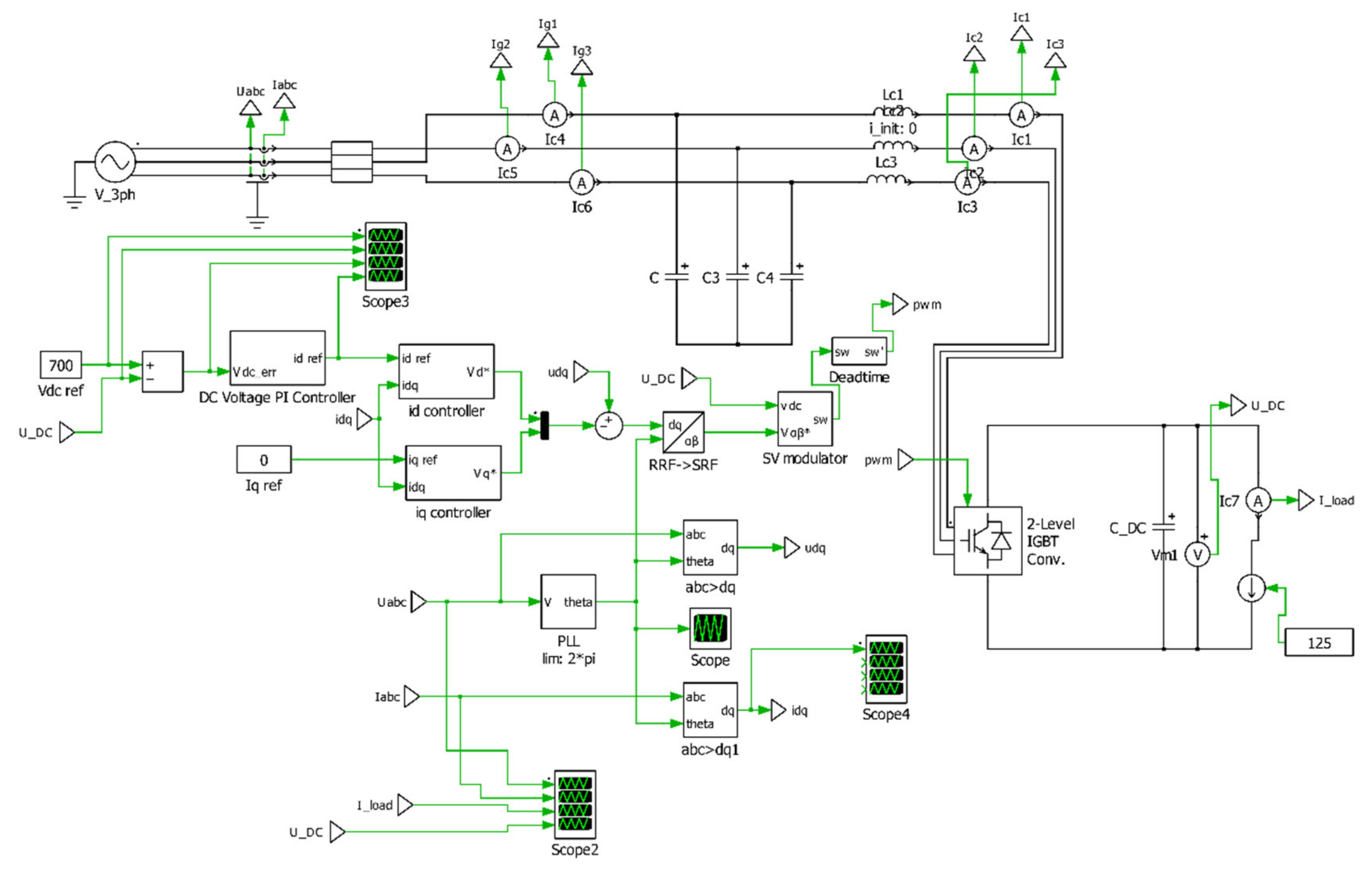
In order to verify the assumptions and theoretical analyses, simulation models of the converters were developed in the PLECS environment and tested. The converter design procedure and selection of passive components and tuning regulators were based on [28,29,38,39]. In the first stage of the analysis, the simulation model of the 2-level AC/DC converter was developed and extended with VOC control of the grid side currents and voltages. The block scheme of the model is shown in Figure 5.
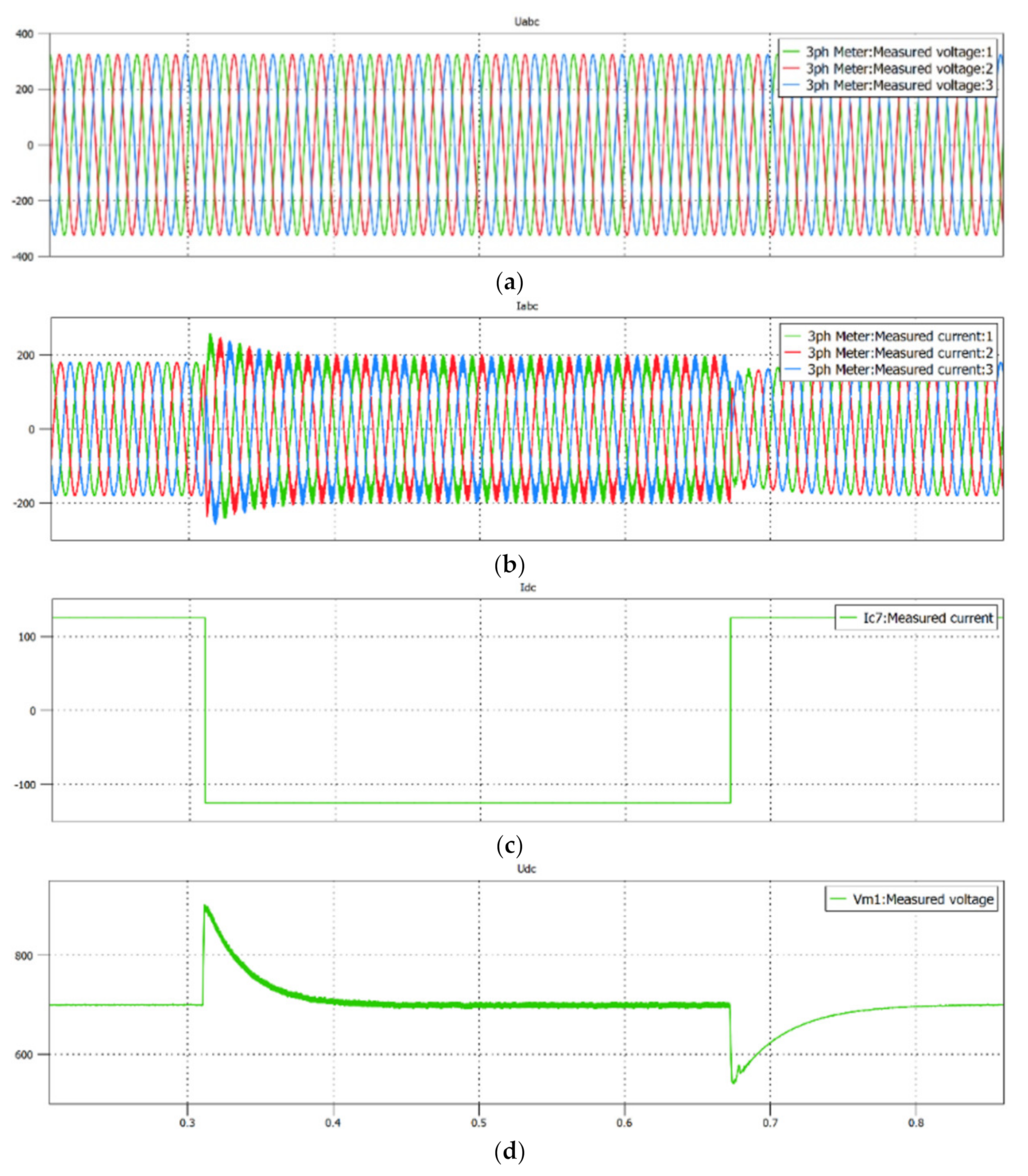
The performed preliminary simulation tests allowed selecting system components determining currents for power transistors, and passive elements. During the simulation analysis, the gains of the PI current regulators in the d and q coordinates were adjusted to obtain satisfying dynamics and shape of the grid side current. In the next step of the analysis, the gain of the DC-link voltage PI regulator was selected. Proper operation of the model with selected parameters was verified in steady states and step load changes. Figure 6 presents the step load change from 85 kW of active power consumed from the grid up to 85 kW of active power restored to the grid and once again up to 85 kW of active power consumed from the grid. The nominal power of the system is 50 kW, therefore, stable operation with overload of up to 85 kW demonstrates satisfying operation of the system.
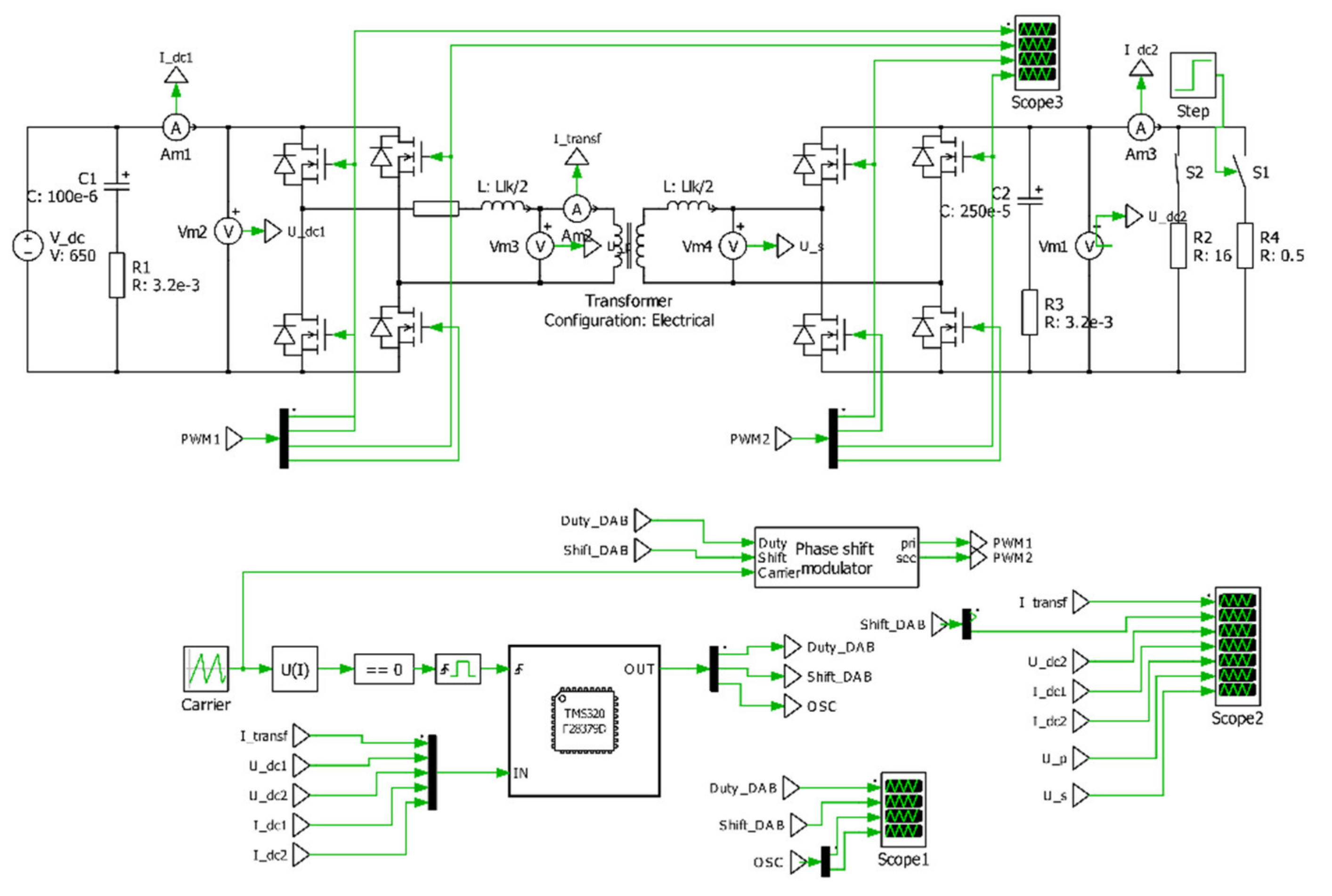
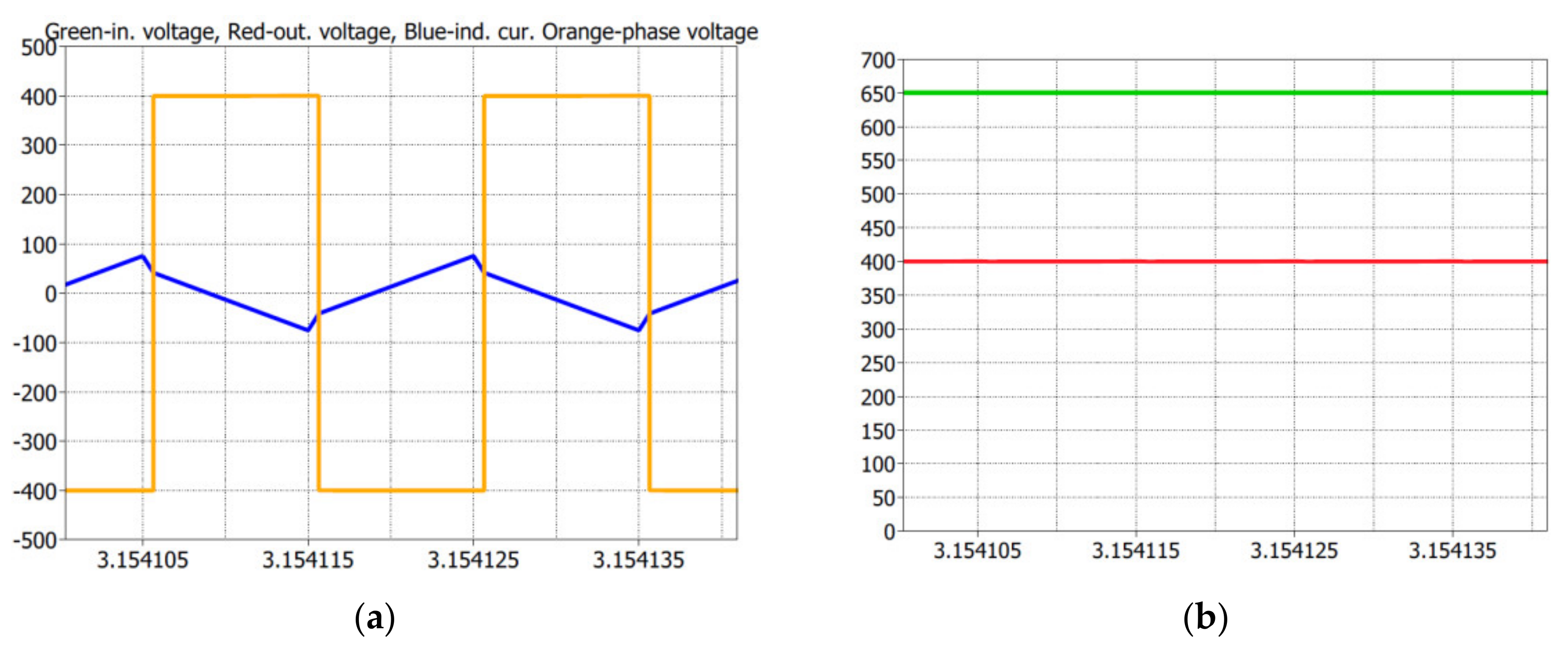
Simultaneously, a dual active bridge (DAB) model was developed in the PLECS environment. Based on the preliminary simulation analysis, the basic parameters of the system, such as switching frequency, current stress of the transistors, and transformer parameters, were determined. To control output currents and voltages, the model was developed with a Phase Shift Controller. The block scheme of the model is shown in Figure 7. The recorded steady state operation of the simulation model is shown in Figure 8.
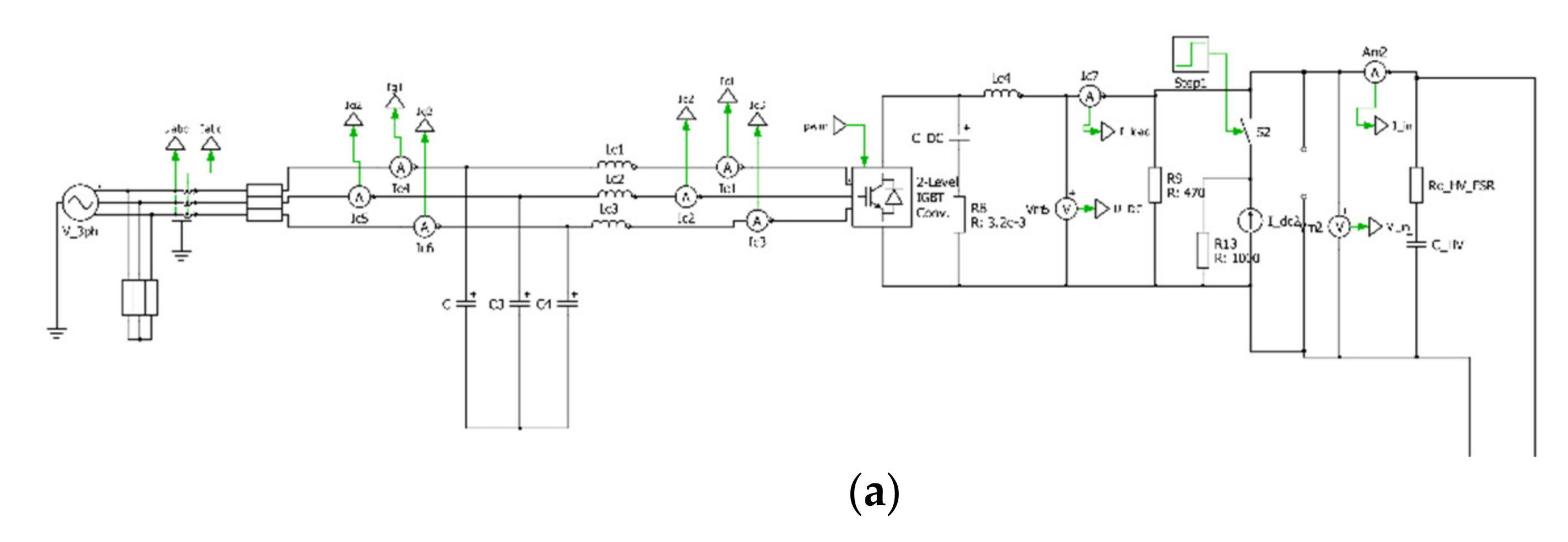
Finally, in order to obtain and analyze a complete system, the AC/DC and DC/DC converter models were integrated in one simulation model created in the PLECS environment. The block scheme of the model is shown in Figure 9.
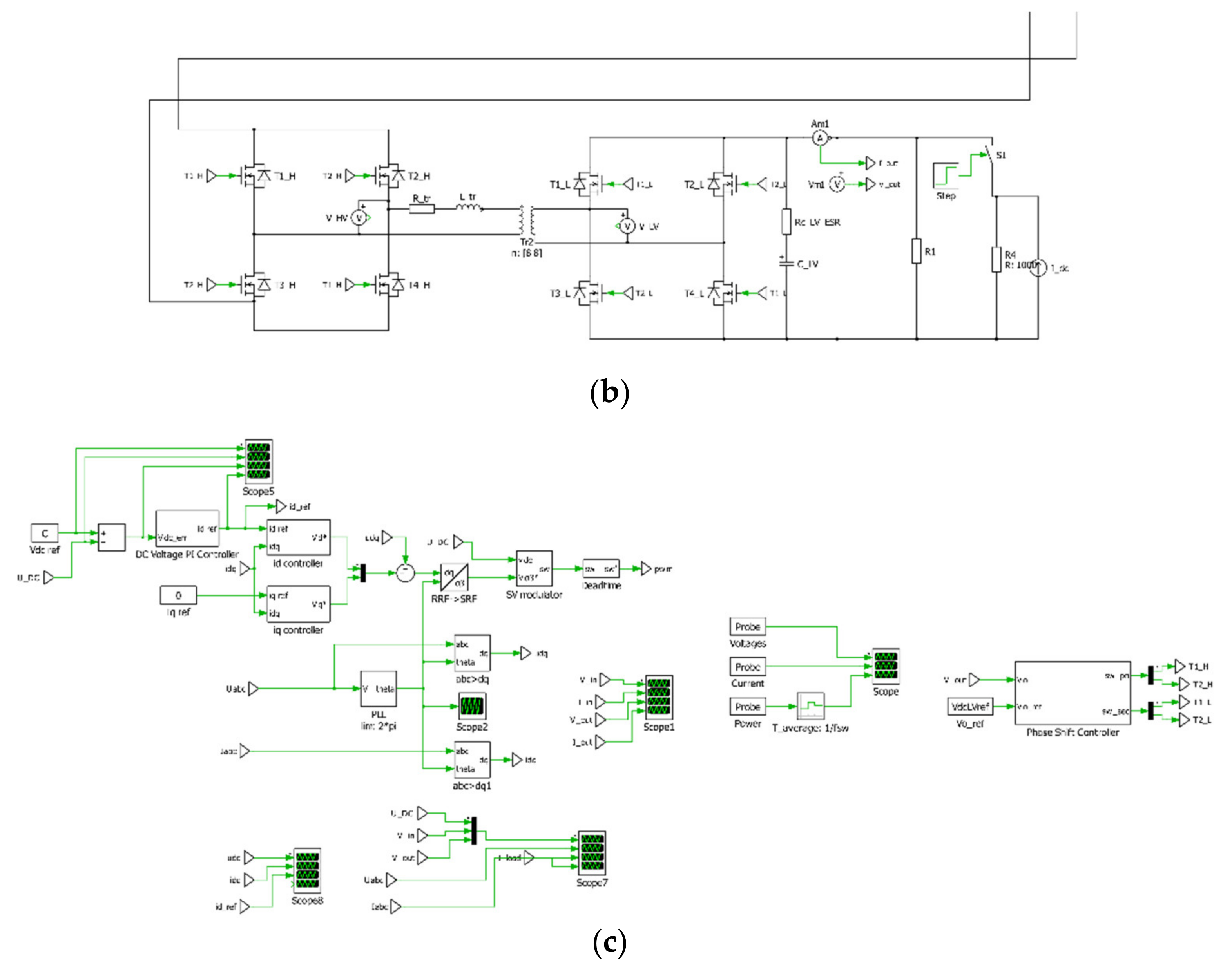
The simulation tests allowed to verify the correct operation of the bi-directional system consisting of two connected converters: the AC/DC input stage, and the DC/DC converter. Due to the complexity of the model, the simulation analysis required considerable computing power. Figure 10 presents the step change from charging to discharging in the operation mode.
4. Experimental Model
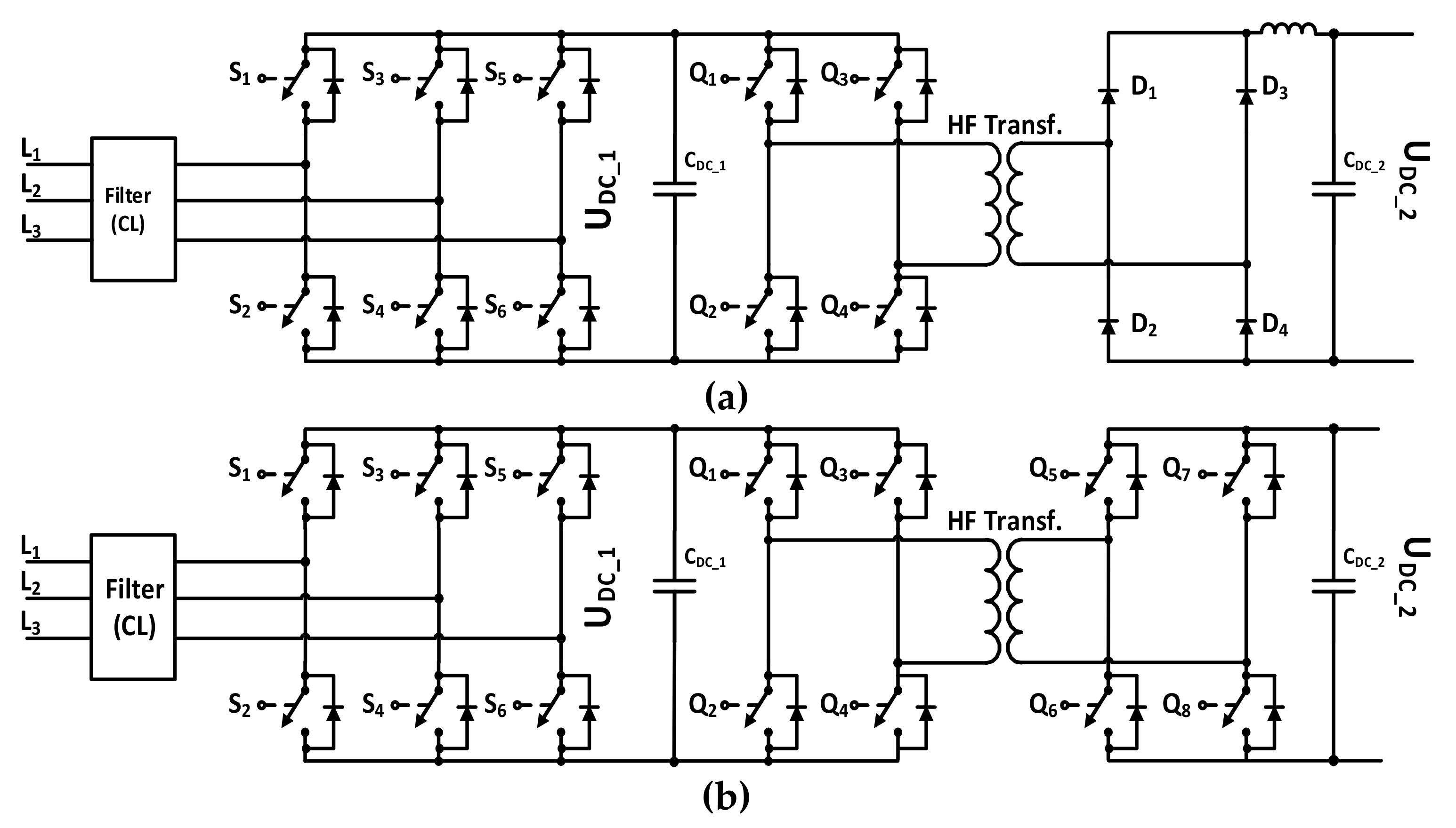
In order to verify the performed theoretical and simulation analyses, two experimental models of AC/DC/DC converters dedicated to charge electric vehicle batteries were created. The first model is the cost effective, flexible for upgrade, and unidirectional charger which consists of a two-level AC/DC converter with an LC filter and a single active bridge (SAB) with a full diode bridge converter, both made in silicon technology using Fuji IGBT modules. The second model is a bidirectional charger which consists of a two-level AC/DC converter with an LC filter and a dual active bridge (DAB). Here, both converters use MOSFET power modules made of silicon carbide by Infineon. Both experimental models were developed in collaboration with Twerd Power Electronics Ltd., Torun, Poland, which supplied the system components. The topology schemes of the analyzed chargers are shown in Figure 11.
5. Experimental Analysis
5.1. Experimental Test Bench
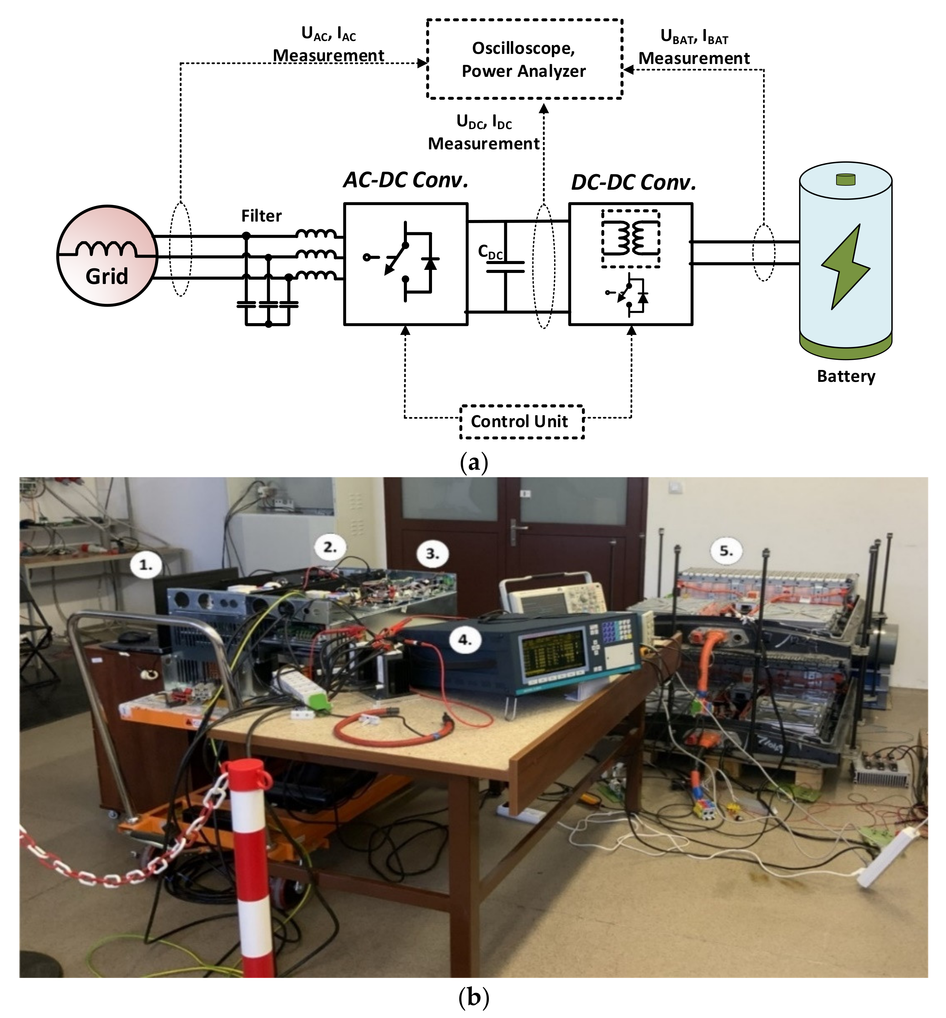
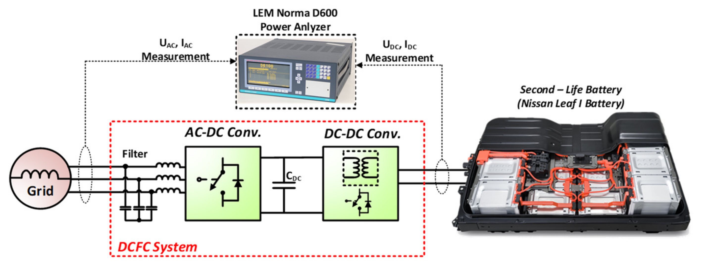
For the experimental analysis of the developed systems, a test bench equipped with B2U-based energy storage was created. The use of B2U was a crucial point for environment protection (lowering carbon footprint) and possible actual applications (reliability of B2U under charging and discharging processes). The block scheme of the laboratory stand is shown in Figure 12a, while its view is presented in Figure 12b. It enabled studying dynamic states and obtaining characteristics recorded during long-term operation of the system. An oscilloscope Tektronix MSO4104 with insulated measuring probes TCP404XL, P5210A was used to record transient states and current and voltage waveforms on the mains and battery sides. To model the charger in conditions close to its real operation, a real B2U energy storage was constructed, which made use of lithium-ion batteries disassembled from electric vehicles (Nissan Leaf I).
5.2. Unidirectional Charger with IGBT Technology
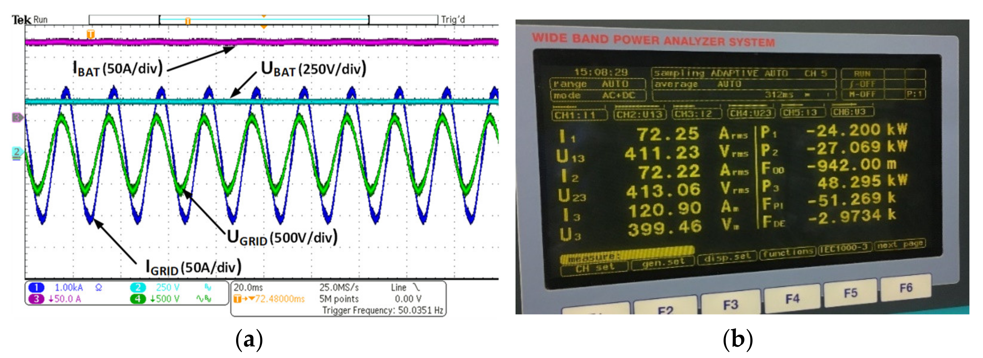
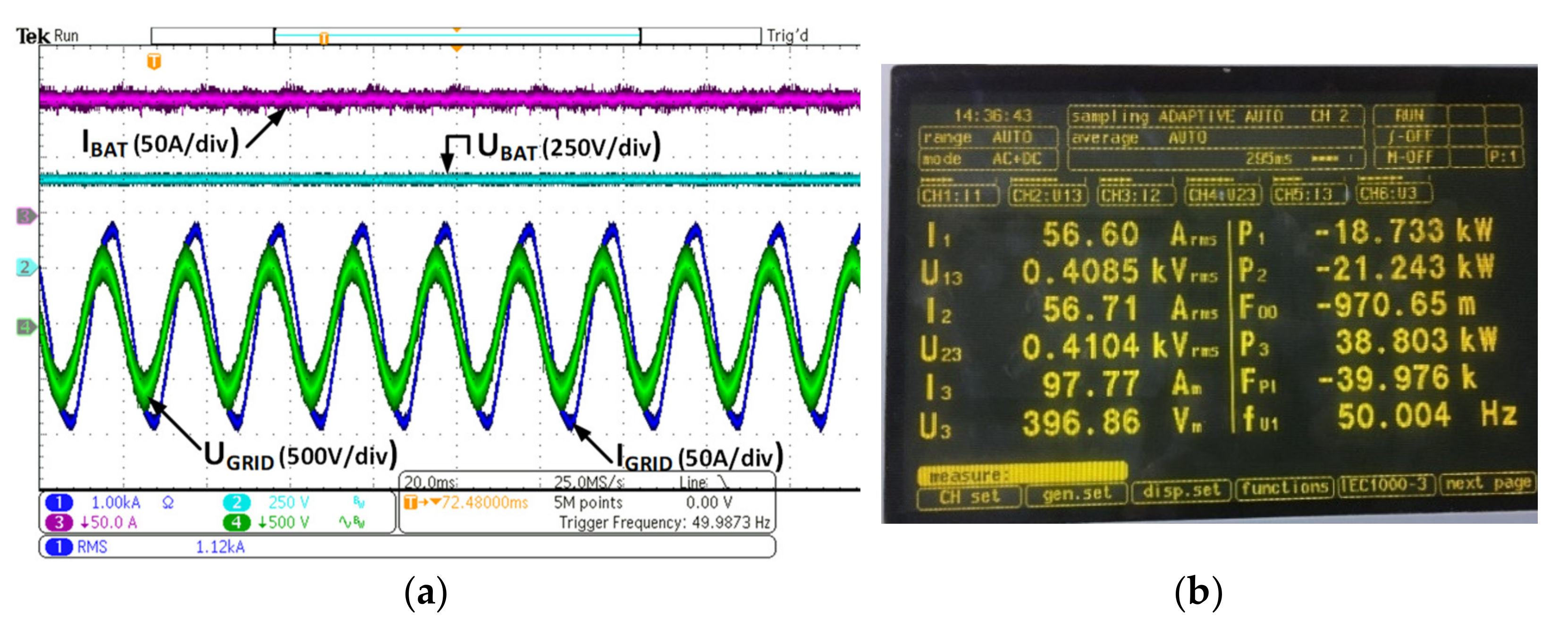
In the first step, the steady-state operation of the unidirectional charger was analyzed. The charger module was connected to the 3 × 400 V grid on the input side (AC) and to the battery on the output side (DC). The load was gradually increased to 100% of the nominal values. A number of tests in dynamic states were also carried out. Figure 13 shows selected waveforms of grid and battery voltages, currents and power, as well as the screen from the LEM Norma Power Analyzer recorded during steady-state operation.
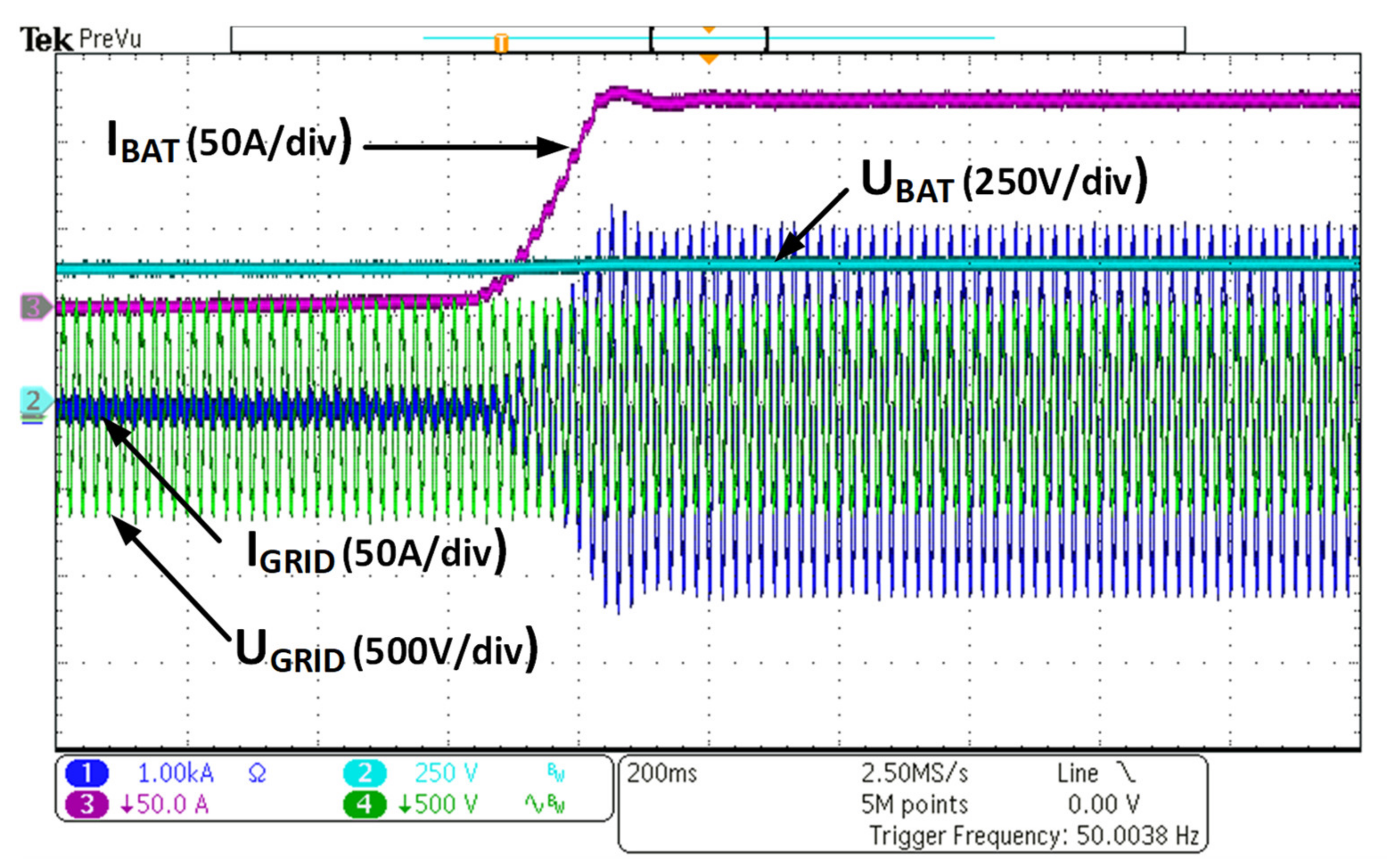
Figure 14 shows the step load change from 5% up to 80% of nominal power during the operation of the unidirectional charger. Satisfactory dynamics and the absence of current overshoot during load changes can be observed. The dynamics of current changes is limited by the dynamics of the battery used and indications of the battery management system (BMS). THD values of current and voltage on the electrical grid side are below 5%, and the system works stably at 400 V and the nominal load of 125 A on the DC side.
5.3. Bidirectional Charger with SiC Technology
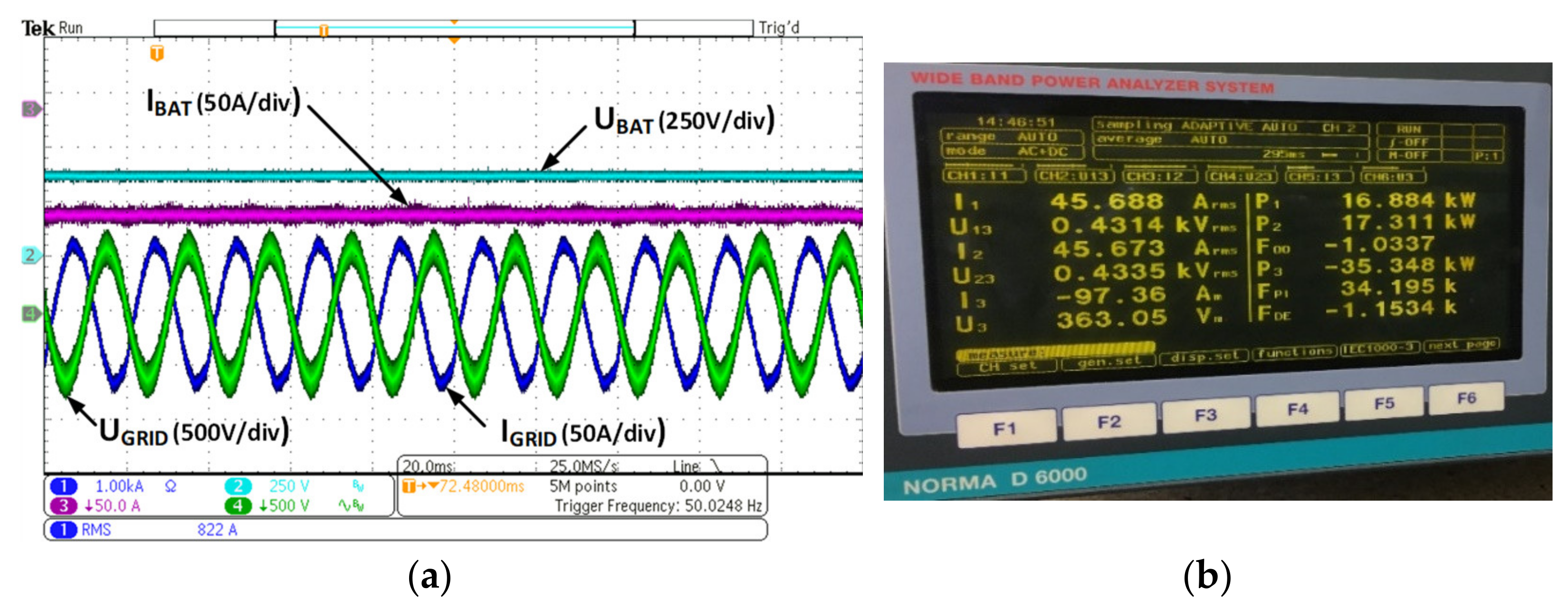
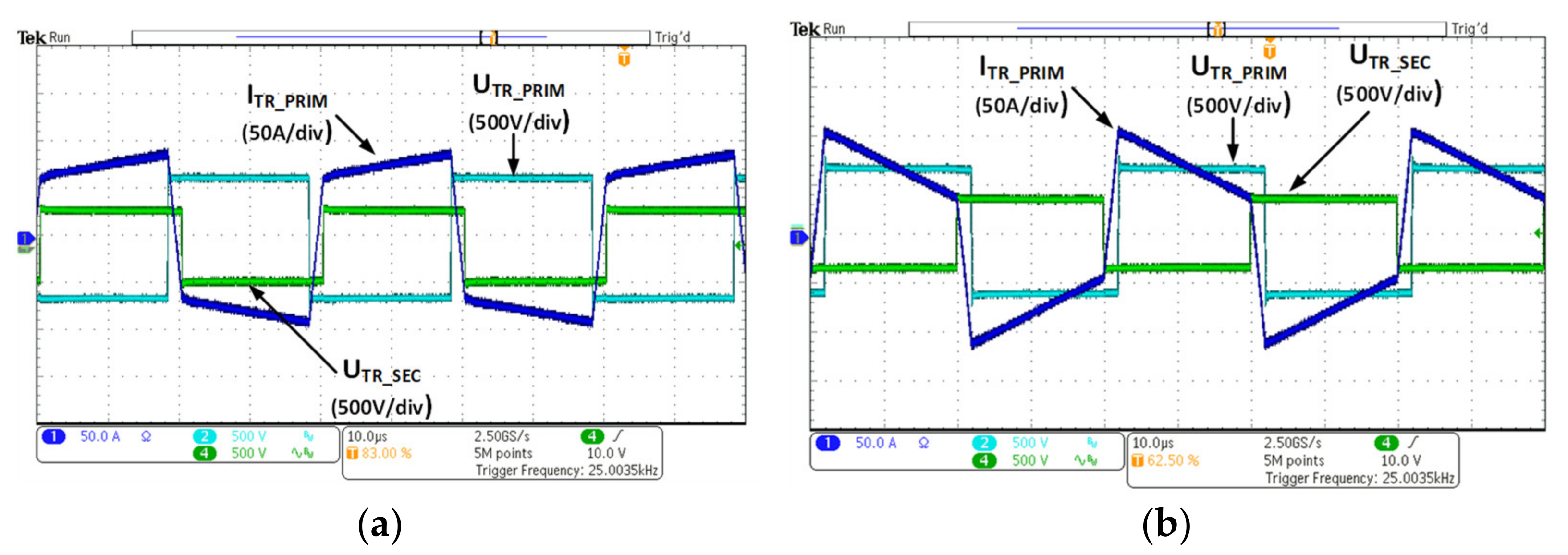
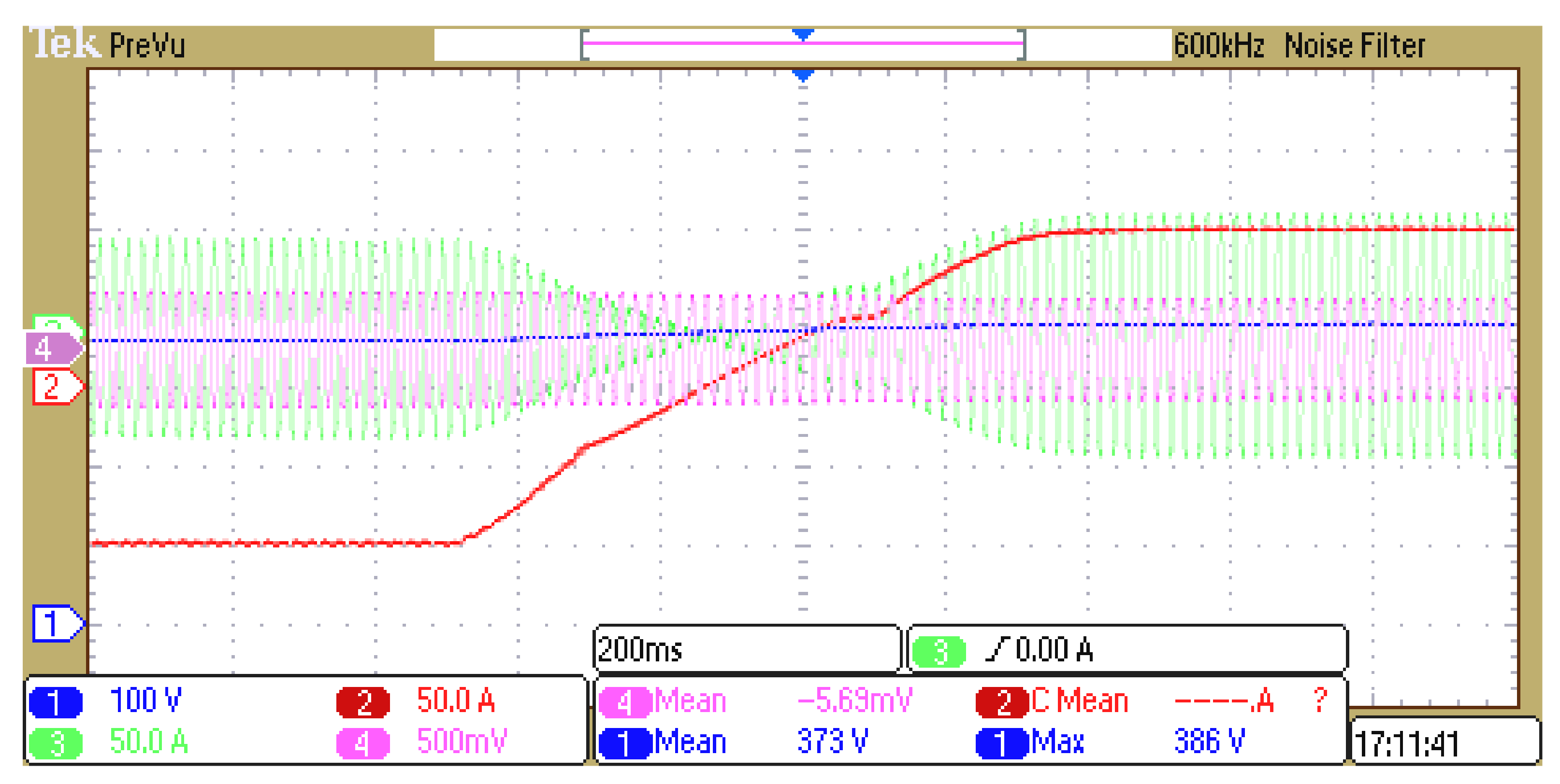
In the next step of the research, a bi-directional charger with silicon carbide power transistors was analyzed. Similar to the previous case, the charger module was connected to the 3 × 400 V grid on the input side (AC) and to the battery on the output side (DC). The load was gradually increased to 100% of the nominal value. Figure 15 shows the steady state when charging the battery with 80% of rated power, while Figure 16 shows the process of discharging the battery, also at 80% of the nominal power of the system. These modes of operation are also shown in Figure 17 on a reduced time scale enabling more detailed observation of the secondary and primary current and voltage waveforms of the DAB converter transformer. A step load change in operation modes from discharging to charging with 80% of the nominal load (100 A DC) is shown in Figure 18.
5.4. Efficiency Measurement
An issue which was individually analyzed was the precise efficiency measurement of charger modules. For this purpose, another test stand, shown in Figure 19, was created. To obtain reliable results, the total efficiency of the charger, defined as the ratio of output power to input power: (including AC/DC and DC/DC converters) was measured. Following the guidelines of the measuring device manufacturer concerning high-quality measurements, the measuring transducers were placed as close as possible to the supply grid (behind the LC filter and EMC filter) on the AC/DC converter side and behind the filter on the DC side (battery current and voltage measurement). Such locations of the measuring transducers allowed to obtain measurement signals with the least possible noise. Obtaining a higher accuracy of the efficiency measurement would be possible using calorimetric tests to analyze the heat released by the system during operation.
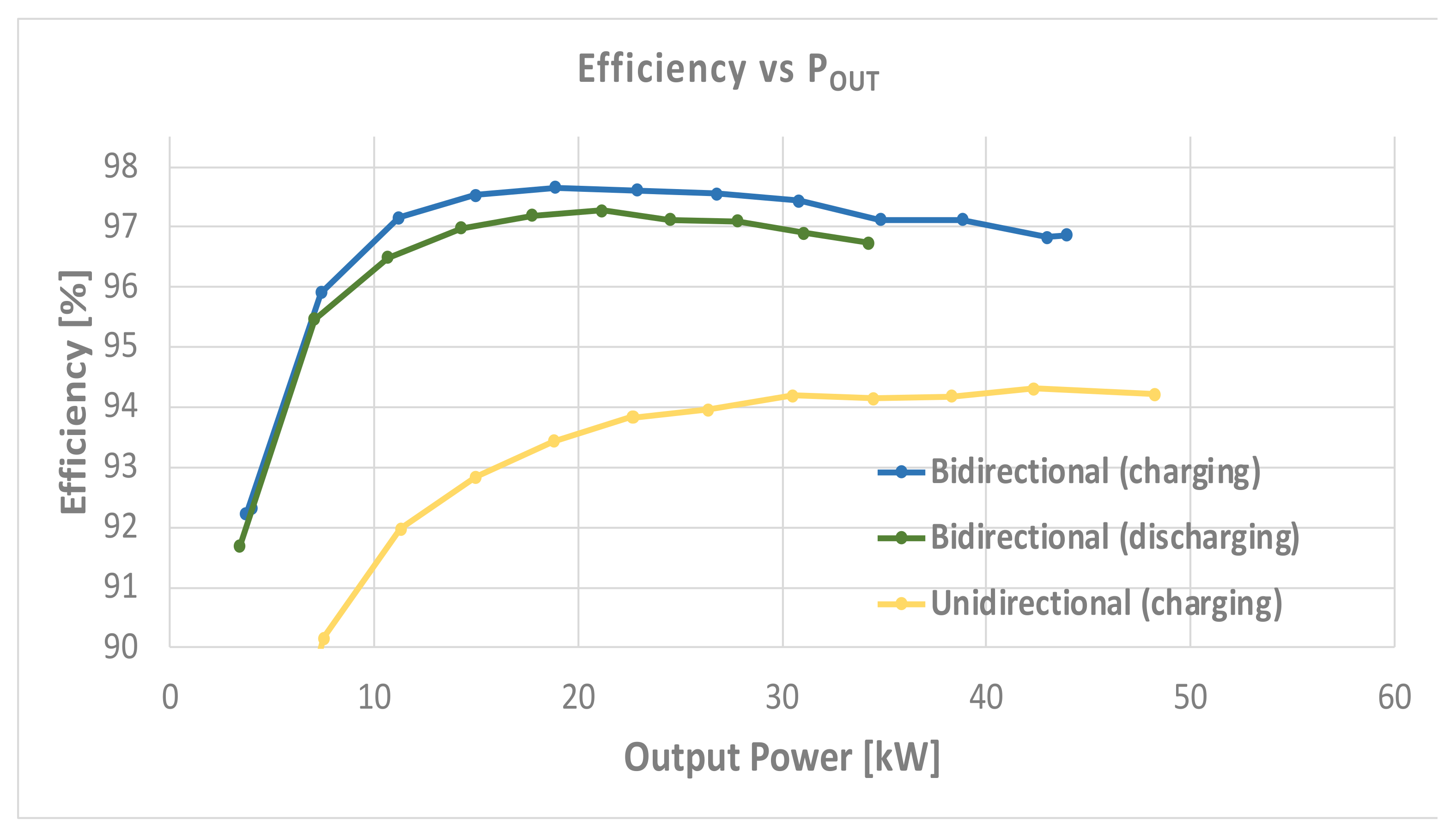
To create the efficiency characteristics of the examined chargers, measurements were carried out with the use of a power analyzer for various charging (and discharging) battery currents. In the unidirectional charger, the efficiency characteristic was obtained for the charging mode, while for the bidirectional charger, it was obtained for both the charging and discharging modes. Due to the type of the battery used, the tests were carried out in the battery voltage range of 360–410 V.
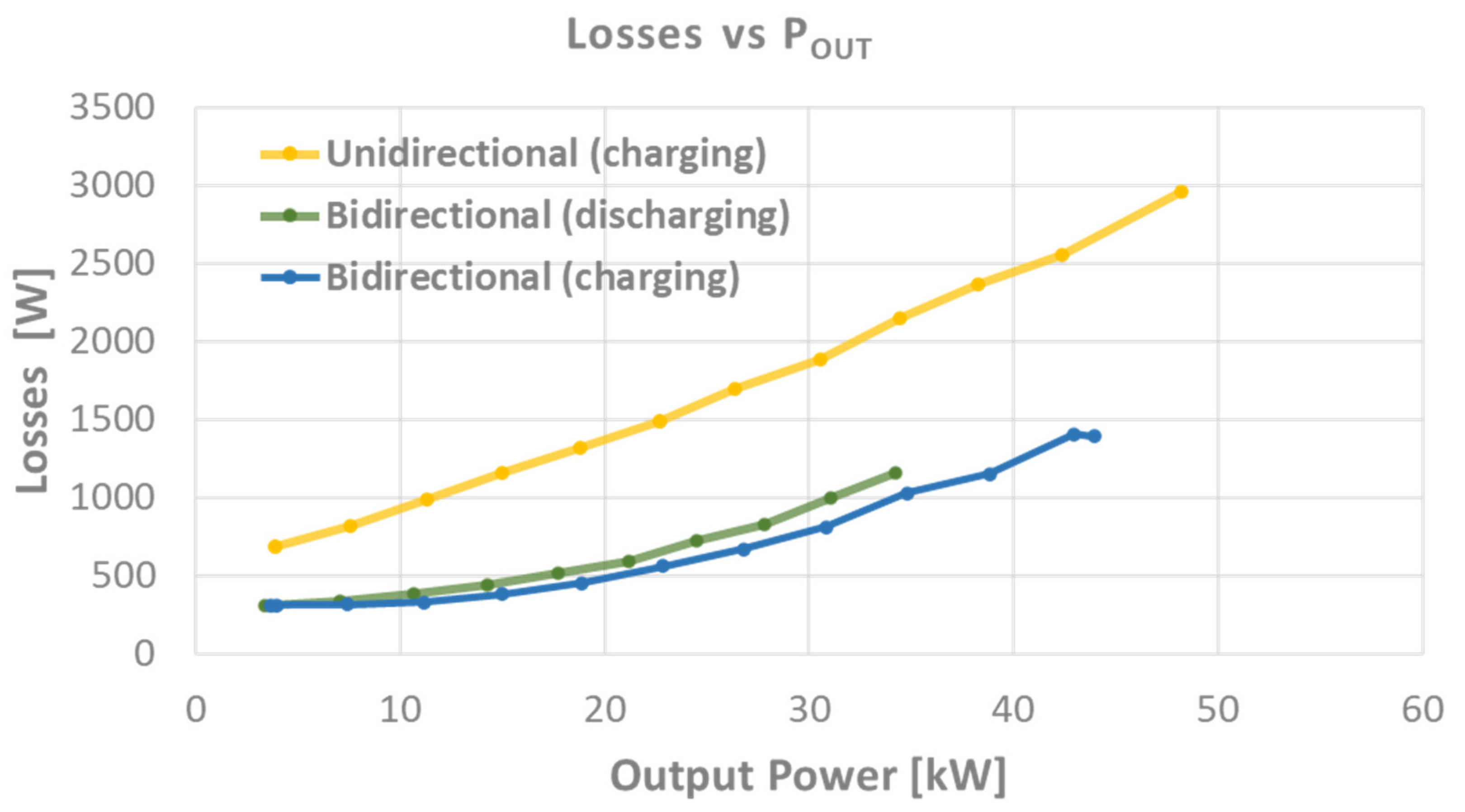
The obtained efficiency vs. output power characteristics are presented in Figure 20, while power losses vs. output power measurements are shown in Figure 21. As can be observed, the efficiency of the bidirectional charger utilizing SiC power transistors is higher by almost 3% than that of the traditional solution based on IGBT modules, which allows reducing the dissipated power losses by more than 1 kW.
6. Discussion and Conclusions
6.1. Conclusions
Thanks to the use of theoretical analyses and simulation tests, the proposed methodology allowed the selection of system components (power transistors, passive elements, voltage range), and initial verification of the proposed control method. The final verification of the properties and parameters of the system took place by examining the experimental model. The obtained results illustrate correct operation of both analyzed charging modules, which ensures the basic required functionality i.e., charging the vehicle battery with a power of up to 50 kW.
The proposed solution, dedicated to electric vehicle fast charging systems, provides:
- −
- galvanic separation between the mains and the vehicle battery;
- −
- modular design, thanks to independent AC/DC and DC/DC converters, which considerably facilitates service work (possibility of replacing individual modules);
- −
- system scalability—the output power can be increased by connecting modules in parallel;
- −
- expansion with additional functionalities, including bidirectional operation and support for V2G systems with the use of a bidirectional DC/DC converter;
- −
- a wide range of output current and voltage regulation (on the vehicle side), thanks to the use of two levels of energy conversion, as a result of which the design can be adapted to various types of batteries.
However, the most significant advantage of the bidirectional charging system using SiC transistors refers to its increased efficiency and improved functionality. Increasing the efficiency by 1 kW allows to reduce the costs of using the station; it can be assumed that every 30th cycle of charging an electric vehicle is free of charge.
Another unquestionable advantage is noise reduction, thanks to the increased switching frequency and the possibility of bidirectional operation. This feature gives the opportunity of integration with future energy systems, in which the V2G standard will be in daily use. In the authors’ opinion, this attribute undoubtedly determines the advantage of the selected bidirectional topology utilizing SiC power switches.
The cost of components for a bidirectional charging system is about 15% higher than that for the unidirectional system, due to higher price of SiC transistors. However, several advantages of this charger compensate for this difference.
From another point of view, if the cost-effective solution needs the topology based on Si technology and the unidirectional power flow is still an alternative because it assures sinusoidal like current at the point of common coupling (PCC) along with good dynamics in the charging process and ready to upgrade functionality, the SAB with diode rectifier could be replaced with SiC DAB topology if the budget and market situation becomes more mature.
6.2. Limitations and Future Works
In the case of a system based on Si transistors, due to switching losses, the switching frequency was limited to 12 kHz. Tests with a higher switching frequency showed a significant increase in power loss. Unfortunately, due to the limitations of the control platform used (based on the TI TMS320F28069 processor), it was not possible to obtain higher switching frequencies for the system with SiC transistors. In the authors’ opinion, such research should be carried out in the future to allow the reduction of passive elements and minimization of system volume.
Moreover, to obtain complete information on the analyzed modules, it seems necessary to extend the efficiency tests to the full output voltage range of 50–500 V DC expected from the DCFC. Due to the type of battery used and its operating parameters, it was impossible to conduct such tests at present. However, the authors plan to extend their range in the future.
As part of future work, the authors also plan to extend the scope of the analysis by including reliability tests of the proposed systems. This seems to be particularly interesting in the case of SiC transistors and increased switching frequency.
In order to obtain greater accuracy of the efficiency measurement, the authors plan to extend the loss measurement by calorimetric tests and to compare the obtained results with those obtained on the basis of power analyzer indications.
It seems advisable to include multi-objective optimization methods in the proposed system design procedure, which would allow optimization of system parameters in terms of efficiency, reliability, and volume or mass reduction. Such works have been undertaken [8,69,70], but due to their complexity, the issues were not conducted for systems with two stages of energy conversion.
Author Contributions
Conceptualization, S.P. and M.J.; methodology, S.P.; software and validation, J.Z.; investigation and resources, J.Z. and S.B.; writing—original draft preparation, S.P.; writing—review and editing, M.J., S.B. and M.T.; project administration and funding acquisition, M.J. All authors have read and agreed to the published version of the manuscript.
Funding
This research was funded from the project entitled “Poland-Taiwan cooperation POLTAJ VII 7th competition Path 1”, co-financed by the National Center for Research and Development.
Institutional Review Board Statement
Not applicable.
Informed Consent Statement
Not applicable.
Data Availability Statement
Not applicable.
Acknowledgments
The authors gratefully acknowledge support from the Institute of Control and Industrial Electronics, Warsaw University of Technology, in covering the publication costs.
Conflicts of Interest
The authors declare no conflict of interest.
References
- Rivera, S.; Kouro, S.; Vazquez, S.; Goetz, S.M.; Lizana, R.; Romero-Cadaval, E. Electric vehicle charging infrastructure: From grid to battery. IEEE Ind. Electron. Mag. 2021, 15, 37–51. [Google Scholar] [CrossRef]
- Matanov, N.; Zahov, A. Developments and Challenges for Electric Vehicle Charging Infrastructure. In Proceedings of the 2020 12th Electrical Engineering Faculty Conference (BulEF), Varna, Bulgaria, 9–12 September 2020; IEEE: Piscataway, NJ, USA, 2020; pp. 1–5. [Google Scholar] [CrossRef]
- Aji, P.; Renata, D.A.; Larasati, D.; Riza. Development of Electric Vehicle Charging Station Management System in Urban Areas. In Proceedings of the 2020 International Conference on Technology and Policy in Energy and Electric Power (ICT-PEP), Bandung, Indonesia, 23–24 September 2020; IEEE: Piscataway, NJ, USA, 2020; pp. 199–203. [Google Scholar] [CrossRef]
- Parchomiuk, M.; Moradewicz, A.; Gawiński, H. An Overview of Electric Vehicles Fast Charging Infrastructure. In Proceedings of the 2019 Progress in Applied Electrical Engineering (PAEE), Koscielisko, Poland, 17–21 June 2019; IEEE: Piscataway, NJ, USA, 2019; pp. 1–5. [Google Scholar] [CrossRef]
- Liu, K.; Hu, X.; Yang, Z.; Xie, Y.; Feng, S. Lithium-ion battery charging management considering economic costs of electrical energy loss and battery degradation. Energy Convers. Manag. 2019, 195, 167–179. [Google Scholar] [CrossRef]
- Li, J. Design and Control Optimisation of a Novel Bypass-Embedded Multilevel Multicell Inverter for Hybrid Electric Vehicle Drives. In Proceedings of the 2020 IEEE 11th International Symposium Power Electronics Distributed Generation Systems PEDG, Dubrovnik, Croatia, 28 September–1 October 2020; IEEE: Piscataway, NJ, USA, 2020; Volume 2, pp. 382–385. [Google Scholar]
- Liu, X.; Yu, F.; Mao, J.; Yang, H. Pre-and post-fault operations of six-phase electric-drive-reconstructed onboard charger for electric vehicles. IEEE Trans. Transp. Electrif. 2021, 7782, 1. [Google Scholar] [CrossRef]
- Liu, K.; Zou, C.; Li, K.; Wik, T. Charging pattern optimization for lithium-ion batteries with an electrothermal-aging model. IEEE Trans. Ind. Inform. 2018, 14, 5463–5474. [Google Scholar] [CrossRef]
- Tu, H.; Feng, H.; Srdic, S.; Lukic, S. Extreme fast charging of electric vehicles: A technology overview. IEEE Trans. Transp. Electrif. 2019, 5, 861–878. [Google Scholar] [CrossRef]
- Iyer, V.M.; Gulur, S.; Gohil, G.; Bhattacharya, S. Extreme fast charging station architecture for electric vehicles with partial power processing. In Proceedings of the 2018 IEEE Applied Power Electronics Conference and Exposition (APEC), San Antonio, TX, USA, 4–8 March 2018; IEEE: Piscataway, NJ, USA, 2018. [Google Scholar] [CrossRef]
- Foley, A.M.; Winning, I.J.; Gallachóir, B.P.Ó.Ó. State-of-the-art in electric vehicle charging infrastructure. In Proceedings of the 2010 IEEE Vehicle Power and Propulsion Conference, Lille, France, 1–3 September 2010; IEEE: Piscataway, NJ, USA, 2014; pp. 1–6. [Google Scholar] [CrossRef]
- Falvo, M.C.; Sbordone, D.; Bayram, I.S.; Devetsikiotis, M. EV charging stations and modes: International standards. In Proceedings of the 2014 International Symposium on Power Electronics, Electrical Drives, Automation and Motion, Ischia, Italy, 18–20 June 2014; IEEE: Piscataway, NJ, USA, 2014; pp. 1134–1139. [Google Scholar] [CrossRef]
- IEC. European Standard IEC 61851-1:2010. Electric Vehicle Conductive Charging System—Part 1: General Requirements; International Electrotechnical Commission: Geneva, Switzerland, 2010. [Google Scholar]
- IEC. European Standard IEC 61851-23:2014. Electric Vehicle Conductive Charging System—Part 23: DC Electric Vehicle Charging Station; International Electrotechnical Commission: Geneva, Switzerland, 2014. [Google Scholar]
- IEC. European Standard IEC 60364-1: Low-Voltage Electrical Installations; International Electrotechnical Commission: Geneva, Switzerland, 2005. [Google Scholar]
- IEC. European Standard IEC 61439-7: Low-Voltage Switchgear and Controlgear Assemblies—Part 7: Assemblies for Specific Applications Such as Marinas, Camping Sites, Market Squares, Electric Vehicle Charging Stations; International Electrotechnical Commission: Geneva, Switzerland, 2018. [Google Scholar]
- SAE. SAE Electric Vehicle and Plug in Hybrid Electric Vehicle Conductive Charge Coupler J1772; SAE International: Warrendale, PA, USA, 2010. [Google Scholar]
- IEC. European Standard IEC 61980 (TC69): Electric Vehicle Wireless Power Transfer (WPT) Systems; International Electrotechnical Commission: Geneva, Switzerland, 2020. [Google Scholar]
- Lee, Z.J.; Lee, G.; Lee, T.; Jin, C.; Lee, R.; Low, Z.; Chang, D.; Ortega, C.; Low, S.H. Adaptive charging networks: A framework for smart electric vehicle charging. IEEE Trans. Smart Grid 2021, 12, 4339–4350. [Google Scholar] [CrossRef]
- Coignard, J.; MacDougall, P.; Stadtmueller, F.; Vrettos, E. Will electric vehicles drive distribution grid upgrades?: The case of California. IEEE Electrif. Mag. 2019, 7, 46–56. [Google Scholar] [CrossRef]
- Yilmaz, M.; Krein, P.T. Review of Battery Charger Topologies, Charging Power Levels, and Infrastructure for Plug-In Electric and Hybrid Vehicles. IEEE Trans. Power Electron. 2012, 28, 2151–2169. [Google Scholar] [CrossRef]
- Tran, V.T.; Sutanto, D.; Muttaqi, K.M. The state of the art of battery charging infrastructure for electrical vehicles: Topologies, power control strategies, and future trend. In Proceedings of the 2017 Australasian Universities Power Engineering Conference (AUPEC), Melbourne, VIC, Australia, 19–22 November 2017; IEEE: Piscataway, NJ, USA, 2018. [Google Scholar] [CrossRef] [Green Version]
- Wali, K.; Koubaa, R.; Krichen, L. Cost benefit smart charging schedule for V2G applications. In Proceedings of the 2019 16th International Multi-Conference on Systems, Signals & Devices (SSD’2019), Istanbul, Turkey, 21–24 March 2019; IEEE: Piscataway, NJ, USA, 2019; pp. 34–39. [Google Scholar] [CrossRef]
- Kratz, S.; Hanses, P.; Krueger, B.; Wegener, R.; Soter, S. Integration of second life batteries into a smart overhead contact system based on SiC-technology. In Proceedings of the 2019 IEEE Transportation Electrification Conference and Expo (ITEC), Detroit, MI, USA, 19–21 June 2019; IEEE: Piscataway, NJ, USA, 2019. [Google Scholar] [CrossRef]
- Zhu, C.; Xu, J.; Liu, K.; Li, X. Feasibility analysis of transportation battery second life used in backup power for communication base station. In Proceedings of the 2017 IEEE Transportation Electrification Conference and Expo, Asia-Pacific (ITEC Asia-Pacific), Chicago, IL, USA, 22–24 June 2017; IEEE: Piscataway, NJ, USA, 2017. [Google Scholar] [CrossRef]
- Liu, K.; Yang, Z.; Tang, X.; Cao, W. Automotive battery equalizers based on joint switched-capacitor and buck-boost converters. IEEE Trans. Veh. Technol. 2020, 69, 12716–12724. [Google Scholar] [CrossRef]
- Liu, K.; Hu, X.; Zhou, H.; Tong, L.; Widanage, W.; Marco, J. Feature analyses and modelling of lithium-ion batteries manufacturing based on random forest classification. IEEE/ASME Trans. Mechatron 2021. [Google Scholar] [CrossRef]
- Wolski, K.; Grzejszczak, P.; Szymczak, M.; Barlik, R. Closed-form formulas for automated design of sic-based phase-shifted full bridge converters in charger applications. Energies 2021, 14, 5380. [Google Scholar] [CrossRef]
- Texas Instruments Design Guide: TIDA-010054. Bidirectional, Dual Active Bridge Reference Design for Level 3 Electric Vehicle Charging Stations. 2021. Available online: www.ti.com (accessed on 9 September 2021).
- Akhila, P.M.; Devi, V. A high frequency resonant EF2 converter for electric vehicle charging. In Proceedings of the 2018 International Conference on Power, Signals, Control and Computation (EPSCICON), Thrissur, India, 6–10 January 2018; IEEE: Piscataway, NJ, USA, 2018; pp. 1–8. [Google Scholar] [CrossRef]
- Dan Gumera, X.; Caberos, A.; Huang, S. Design and Implementation of a High Efficiency Cost Effective EV Charger Using LLC Resonant Converter. In Proceedings of the 2017 Asian Conference on Energy, Power and Transportation Electrification (ACEPT), Singapore, 24–26 October 2017; IEEE: Piscataway, NJ, USA, 2017; pp. 1–6. [Google Scholar] [CrossRef]
- Kim, D.-H.; Kim, M.-S.; Nengroo, S.H.; Kim, C.-H.; Kim, H.-J. LLC resonant converter for LEV (Light Electric Vehicle) fast chargers. Electronics 2019, 8, 362. [Google Scholar] [CrossRef] [Green Version]
- Hua, C.; Fang, Y.; Lin, C. A new LLC converter for electric vehicles battery charger. In Proceedings of the 2015 18th International Conference on Electrical Machines and Systems (ICEMS), Pattaya, Thailand, 25–28 October 2015; IEEE: Piscataway, NJ, USA, 2015; pp. 768–772. [Google Scholar] [CrossRef]
- Zahid, Z.U.; Dalala, Z.; Lai, J.J. Design and control of bidirectional resonant converter for Vehicle-to-Grid (V2G) applications. In Proceedings of the IECON 2014—40th Annual Conference of the IEEE Industrial Electronics Society, Dallas, TX, USA, 29 October–1 November 2014; IEEE: Piscataway, NJ, USA, 2015; pp. 1370–1376. [Google Scholar] [CrossRef]
- Arazi, M.; Payman, A.; Camara, M.B.; Dakyo, B. Analysis of a bidirectional resonant converter for wide battery voltage range in electric vehicles application. In Proceedings of the 2017 IEEE Vehicle Power and Propulsion Conference (VPPC), Belfort, France, 11–14 December 2017; IEEE: Piscataway, NJ, USA, 2018; pp. 1–6. [Google Scholar] [CrossRef]
- Han, J.; Zhou, X.; Lu, S.; Zhao, P. A Three-Phase Bidirectional Grid-Connected AC/DC Converter for V2G Applications. J. Control Sci. Eng. 2020, 2020, 1–12. [Google Scholar] [CrossRef]
- Jasinski, M.; Wrona, G.; Piasecki, S. Control of grid connected converter (GCC) under grid voltage disturbances. In Advanced and Intelligent Control in Power Electronics and Drives; Orlowska-Kowalska, T., Blaabjerg, F., Rodriguez, J., Eds.; Springer: Berlin/Heidelberg, Germany, 2014; Volume 531, pp. 91–142. [Google Scholar]
- Teodorescu, R.; Liserre, M.; Rodríguez, P. Grid Converters for Photovoltaic and Wind Power Systems; Wiley-IEEE: New York, NY, USA, 2007. [Google Scholar]
- Elma, O.; Adham, M.I.; Gabbar, H.A. Effects of Ultra-Fast Charging System for Battery Size of Public Electric Bus. In Proceedings of the 2020 IEEE 8th International Conference on Smart Energy Grid Engineering (SEGE), Oshawa, ON, Canada, 12–14 August 2020; IEEE: Piscataway, NJ, USA, 2020. [Google Scholar] [CrossRef]
- Leone, C.; Longo, M. Modular approach to ultra-fast charging stations. J. Electr. Eng. Technol. 2021, 16, 1971–1984. [Google Scholar] [CrossRef]
- Piasecki, S.; Jasiński, M.; Milicua, A. Brief view on control of grid-interfacing AC-DC-AC converter and active filter under unbalanced and distorted voltage conditions. COMPEL Int. J. Comput. Math. Electr. 2011, 30, 351–373. [Google Scholar] [CrossRef]
- Battery Second Use for Plug-In Electric Vehicles. Available online: https://www.nrel.gov/transportation/battery-second-use.html (accessed on 20 September 2021).
- Rosso, R.; Wang, X.; Liserre, M.; Lu, X.; Engelken, S. Grid-forming converters: An overview of control approaches and future trends. In Proceedings of the 2020 IEEE Energy Conversion Congress and Exposition (ECCE), Detroit, MI, USA, 11–15 October 2020; IEEE: Piscataway, NJ, USA, 2020; pp. 4292–4299. [Google Scholar] [CrossRef]
- San-Sebastián, J.; Etxeberria-Otadui, I.; Rujas, A.; Barrena, J.A.; Rodriguez, P. Optimized LCL filter design methodology applied to MV grid-connected multimegawatt VSC. In Proceedings of the IEEE Energy Conversion Congress and Exposition (ECCE 2012), Raleigh, NC, USA, 15–20 September 2012; IEEE: Piscataway, NJ, USA, 2012; pp. 2506–2512. [Google Scholar]
- Muhlethaler, J.; Schweizer, M.; Blattmann, R.; Kolar, J.W.; Ecklebe, A. Optimal design of LCL harmonic filters for three-phase pfc rectifiers. IEEE Trans. Power Electron. 2013, 28, 3114–3125. [Google Scholar] [CrossRef]
- Jalili, K.; Bernet, S. Design of LCL Filters of Active-Front-End Two-Level Voltage-Source Converters. IEEE Trans. Ind. Electron. 2009, 56, 1674–1689. [Google Scholar] [CrossRef]
- Bloemink, J.M.; Green, T.C. Reducing passive filter sizes with tuned traps for distribution level power electronics. In Proceedings of the 14th European Conference on Power Electronics and Applications (EPE 2011), Birmingham, UK, 30 August–1 September 2011; IEEE: Piscataway, NJ, USA, 2011; pp. 1–9. [Google Scholar]
- Liserre, M.; Blaabjerg, F.; Hansen, S. Design and control of an LCL-filter-based three-phase active rectifier. IEEE Trans. Ind. Appl. 2005, 41, 1281–1291. [Google Scholar] [CrossRef]
- Teichmann, R.; Malinowski, M.; Bernet, S. Evaluation of three-level rectifiers for low-voltage utility applications. IEEE Trans. Ind. Electron. 2005, 52, 471–481. [Google Scholar] [CrossRef]
- Piasecki, S. High order line filters for grid connected AC-DC converter—parameters selection and optimization. In Proceedings of the 23rd IEEE International Symposium on Industrial Electronics (ISIE 2014), Istanbul, Turkey, 1–4 June 2014; IEEE: Piscataway, NJ, USA, 2014; pp. 2687–2692. [Google Scholar]
- Piasecki, S.; Cantarellas, A.M.; Rabkowski, J.; Rodriguez, P. Design of AC-DC power converters with LCL + tuned trap line filter using Si IGBT and SiC MOSFET modules. In Proceedings of the 39th Annual Conference of the IEEE Industrial Electronics Society (IECON 2013), Vienna, Austria, 10–13 November 2013; IEEE: Piscataway, NJ, USA, 2013; pp. 5955–5960. [Google Scholar]
- Styński, S. Analysis and Control of Multilevel AC–DC–AC Flying Capacitor Converter Fed from Single–Phase Grid. Ph.D. Thesis, Warsaw University of Technology, Warsaw, Poland, 2011. [Google Scholar]
- Kołomyjski, W. Modulation Strategies for Three-level PWM Converter-Fed Induction Machine Drives. Ph.D. Thesis, Warsaw University of Technology, Warsaw, Poland, 2009. [Google Scholar]
- Kazmierkowski, M.P.; Krishnan, R.; Blaabjerg, F. Control in Power Electronics. Selected Problems; Academic Press: Cambridge, MA, USA, 2002. [Google Scholar]
- Jasinski, M.; Wrona, G.; Piasecki, S. Advanced and Intelligent Control in Power Electronics and Drives, Chapter 3: Control of Grid Connected Converter (GCC) Under Grid Voltage Disturbances; Springer International Publishing: New York, NY, USA, 2014; Volume 531. [Google Scholar]
- Jasinski, M. Direct Power and Torque Control of AC/DC/AC Converter-Fed Induction Motor Drives. Ph.D. Thesis, Warsaw University of Technology, Warsaw, Poland, 2005. [Google Scholar]
- Malinowski, M. Sensorless Control Strategies for Three—Phase PWM Rectifiers. Ph.D. Thesis, Warsaw University of Technology, Warsaw, Poland, 2001. [Google Scholar]
- Farzan Moghaddam, A.; Van den Bossche, A. Flyback converter balancing technique for lithium based batteries. In Proceedings of the 2019 8th International Conference on Modern Circuits and Systems Technologies (MOCAST), Thessaloniki, Greece, 13–15 May 2019; IEEE: Piscataway, NJ, USA, 2019; pp. 1–4. [Google Scholar] [CrossRef]
- Yang, J.-W.; Do, H.-L. Soft-Switching Dual-Flyback DC–DC Converter with Improved Efficiency and Reduced Output Ripple Current. IEEE Trans. Ind. Electron. 2017, 64, 3587–3594. [Google Scholar] [CrossRef]
- Ekkaravarodome, C.; Bilsalam, A.; Pattarapongsathit, W.; Thounthong, P. DC-DC high conversion ratio push-pull resonant converter based on voltage double rectifier. In Proceedings of the 2019 Research, Invention, and Innovation Congress (RI2C), Bangkok, Thailand, 11–13 December 2019; IEEE: Piscataway, NJ, USA, 2019; pp. 1–5. [Google Scholar] [CrossRef]
- Barlik, R.; Nowak, M.; Grzejszczak, P. Power transfer analysis in a single phase dual active bridge. Bull. Pol. Acad. Sci. Tech. Sci. 2013, 61, 809–828. [Google Scholar] [CrossRef] [Green Version]
- Baba, S.; Bachman, S.; Jasinski, M.; Zelechowski, M. WBG-based PEBB module for high reliability power converters. IEEE Access 2021, 9, 1. [Google Scholar] [CrossRef]
- Bachman, S.; Baba, S.; Jasinski, M. A wide-bandgap based Power Electronic Building Block for reliable modular power converter. In Proceedings of the 2021 IEEE 19th International Power Electronics and Motion Control Conference (PEMC), Gliwice, Poland, 25–29 April 2021; IEEE: Piscataway, NJ, USA, 2021; pp. 46–52. [Google Scholar] [CrossRef]
- Hillers, A.; Christen, D.; Biela, J. Design of a highly efficient bidirectional isolated LLC resonant converter. In Proceedings of the 2012 15th International Power Electronics and Motion Control Conference (EPE/PEMC), Novi Sad, Serbia, 4–6 September 2012; IEEE: Piscataway, NJ, USA, 2013; pp. DS2b.13-1–DS2b.13-8. [Google Scholar] [CrossRef]
- Rahman, A.N.; Lee, C.; Chiu, H.; Hsieh, Y. Bidirectional Three-Phase LLC Resonant Converter. In Proceedings of the 2018 IEEE Transportation Electrification Conference and Expo, Asia-Pacific (ITEC Asia-Pacific), Bangkok, Thailand, 6–9 June 2018; IEEE: Piscataway, NJ, USA, 2018; pp. 1–5. [Google Scholar] [CrossRef]
- Krismer, F. Modeling and Optimization of Bidirectional Dual Active Bridge DC–DC Converter Topologies. Ph.D. Thesis, ETH Zürich, Zürich, Switzerland, 2010. [Google Scholar]
- JJung, J.-H.; Kim, H.-S.; Kim, J.-H.; Ryu, M.-H.; Baek, J.-W. High efficiency bidirectional LLC resonant converter for 380V DC power distribution system using digital control scheme. In Proceedings of the 2012 Twenty-Seventh Annual IEEE Applied Power Electronics Conference and Exposition (APEC), Orlando, FL, USA, 5–9 February 2012; IEEE: Piscataway, NJ, USA, 2012; pp. 532–538. [Google Scholar] [CrossRef]
- Chen, W.; Rong, P.; Lu, Z. Snubberless Bidirectional DC–DC Converter with New CLLC Resonant Tank Featuring Minimized Switching Loss. IEEE Trans. Ind. Electron. 2009, 57, 3075–3086. [Google Scholar] [CrossRef]
- Piasecki, S.; Szmurlo, R.; Rabkowski, J.; Kazmierkowski, M.P. Advances in data analysis with computational intelligence methods. In A Method of Design and Optimization for SiC-Based Grid-Connected AC-DC Converters; Springer International Publishing: New York, NY, USA, 2018; pp. 395–412. [Google Scholar] [CrossRef]
- Piasecki, S.; Szmurło, R.; Rąbkowski, J.; Jasiński, M. Dedicated system for design, analysis and optimization of the AC-DC converters. Bull. Pol. Acad. Sci. Tech. Sci. 2016, 64, 897–905. [Google Scholar] [CrossRef] [Green Version]
Figure 1.
Block scheme of the analyzed Direct Current Fast Charger.

Figure 2.
Block schemes of active AC/DC converter topologies: (a) 2-level Voltage Source Converter (VSC); (b) 3-level Floating Capacitor Converter (FLC); (c) 3-level T-type converter; (d) Neutral Point Clamped Converter (NPC).
Figure 2.
Block schemes of active AC/DC converter topologies: (a) 2-level Voltage Source Converter (VSC); (b) 3-level Floating Capacitor Converter (FLC); (c) 3-level T-type converter; (d) Neutral Point Clamped Converter (NPC).

Figure 3.
Regulation schemes of active AC/DC converters: (a) Voltage Oriented Control (VOC); (b) Direct Power Control with Space Vector Modulation (DPC-SVM).
Figure 3.
Regulation schemes of active AC/DC converters: (a) Voltage Oriented Control (VOC); (b) Direct Power Control with Space Vector Modulation (DPC-SVM).

Figure 4.
Block schemes of the considered DC/DC converter topologies: (a) single active bridge (SAB); (b) dual active bridge (DAB); (c) DAB-CLLC resonant converter.
Figure 4.
Block schemes of the considered DC/DC converter topologies: (a) single active bridge (SAB); (b) dual active bridge (DAB); (c) DAB-CLLC resonant converter.

Figure 5.
Simulation model of 2-level AC/DC converter module with VOC control developed in PLECS environment.
Figure 5.
Simulation model of 2-level AC/DC converter module with VOC control developed in PLECS environment.

Figure 6.
Simulation result—step load changes of AC/DC converter, from 85 kW of active power consumed from the grid, through 85 kW of active power restored to the grid, up to 85 kW consumed from the grid: (a) grid voltages; (b) grid currents; (c) DC-link current; (d) DC-link voltage.
Figure 6.
Simulation result—step load changes of AC/DC converter, from 85 kW of active power consumed from the grid, through 85 kW of active power restored to the grid, up to 85 kW consumed from the grid: (a) grid voltages; (b) grid currents; (c) DC-link current; (d) DC-link voltage.

Figure 7.
Simulation model of dual active bridge (DAB) converter module with a Phase Shift Controller developed in the PLECS environment.
Figure 7.
Simulation model of dual active bridge (DAB) converter module with a Phase Shift Controller developed in the PLECS environment.

Figure 8.
Simulation result—operation of the DC/DC converter during steady state: (a) phase voltage (orange) and transformer current (blue); (b) input voltage (green), output voltage (red).
Figure 8.
Simulation result—operation of the DC/DC converter during steady state: (a) phase voltage (orange) and transformer current (blue); (b) input voltage (green), output voltage (red).

Figure 9.
Developed in the PLECS environment, a simulation model of direct-current fast charger composed of: (a) 2-level AC/DC converter module; (b) DC/DC DAB converter module; (c) control algorithms: VOC control for AC/DC converter and a Phase Shift Controller for the DC/DC converter.
Figure 9.
Developed in the PLECS environment, a simulation model of direct-current fast charger composed of: (a) 2-level AC/DC converter module; (b) DC/DC DAB converter module; (c) control algorithms: VOC control for AC/DC converter and a Phase Shift Controller for the DC/DC converter.


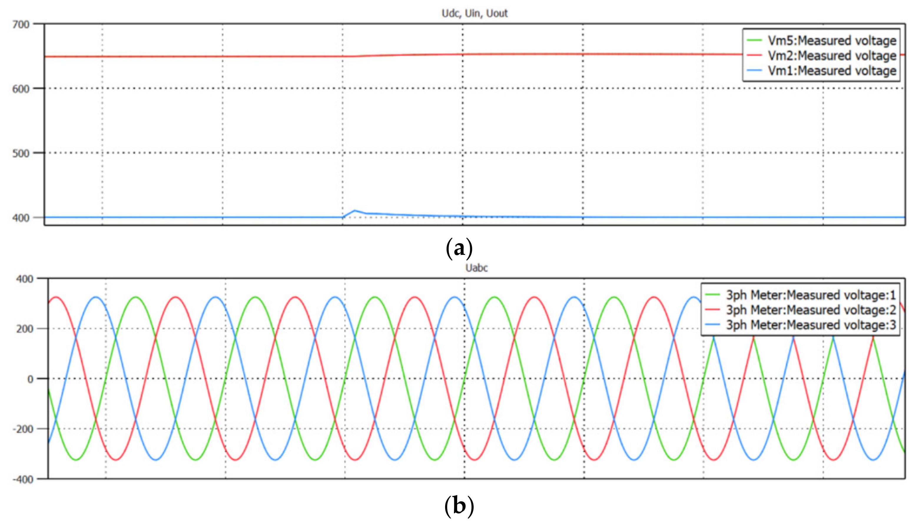
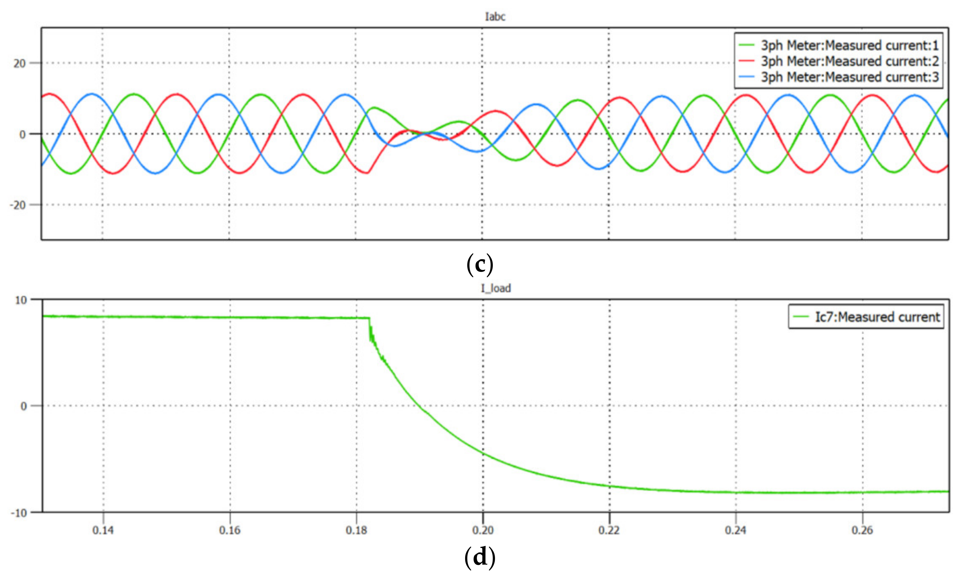
Figure 10.
Simulation result—step change of bi-directional direct-current fast charger from charging operation mode to battery discharging operation mode: (a) DAB’s input voltage (red), DAB’s output voltage (battery voltage)—blue; (b) grid phase voltages; (c) grid phase currents; (d) battery current (green).


Figure 11.
Block scheme of charger prototypes analyzed in experimental study: (a) unidirectional charger with a 2-level AC/DC converter and a DC/DC converter composed of single-phase bridge and a full bridge diode rectifier in Si technology; (b) bidirectional charger with 2-level AC/DC converter and DC/DC converter composed of a dual active bridge (DAB) in SiC technology.

Figure 12.
Experimental test bench used during the research: (a) block scheme; (b) view of the test bench: 1.—control platform; 2.—50 kW unidirectional charger made in IGBT technology composed of 2-level AC/DC and SAB converters; 3.—50 kW bidirectional charger made in SiC technology composed of 2-level AC/DC and DAB converters; 4.—LEM NORMA D6000 power analyzer (provided by Warsaw University of Technology, Warsaw, Poland); 5.—energy storage constructed from batteries of electric vehicles (Nissan Leaf).

Figure 13.
Operation of unidirectional charger under nominal conditions—steady state: (a) current and voltage waveforms, from the top: battery current (purple), battery voltage (light blue), AC phase current (dark blue), AC line-to-line voltage (green); (b) printed screen from the LEM NORMA Power Analyzer.

Figure 14.
Operation of the unidirectional charger—step load change from 5% up to 80% of nominal power, from the top: battery current (purple), battery voltage (light blue), AC phase current (dark blue), AC line-to-line voltage (green).
Figure 14.
Operation of the unidirectional charger—step load change from 5% up to 80% of nominal power, from the top: battery current (purple), battery voltage (light blue), AC phase current (dark blue), AC line-to-line voltage (green).

Figure 15.
Operation of the bidirectional charger under nominal conditions—steady state, charging mode: (a) current and voltage waveforms, from the top: battery current (purple), battery voltage (light blue), AC phase current (dark blue), AC line-to-line voltage (green); (b) printed screen from the LEM NORMA power analyzer.

Figure 16.
Operation of the bidirectional charger under nominal conditions—steady-state, discharging mode: (a) current and voltage waveforms, from the top: battery current (purple), battery voltage (light blue), AC phase current (dark blue), AC line-to-line voltage (green); (b) printed screen from the LEM NORMA power analyzer.

Figure 17.
Operation of the dual active bridge (DAB) in the bidirectional charger (reduced time scale)—steady state: (a) charging mode, (b) discharging mode, from the top: transformer current at the primary side (dark blue), voltage of the primary side (light blue), voltage of the secondary side (green).

Figure 18.
Operation of the bidirectional charger—step load change from discharging to charging mode with 80% of nominal load (100 A), from the top: battery current (red), AC phase current (green), AC line-to-line voltage (purple); battery voltage (dark blue).
Figure 18.
Operation of the bidirectional charger—step load change from discharging to charging mode with 80% of nominal load (100 A), from the top: battery current (red), AC phase current (green), AC line-to-line voltage (purple); battery voltage (dark blue).

Figure 19.
Configuration of the experimental test bench for efficiency measurement.

Figure 20.
Efficiency characteristics vs. output power (POUT) of the analyzed DCFC systems for different operation modes, from the top: efficiency characteristic of bidirectional charger with SiC power transistors during charging mode (dark blue); efficiency characteristic of bidirectional charger with SiC power transistors during discharging mode (dark green); efficiency characteristic of unidirectional charger with IGBT power transistors during charging mode (yellow). Battery voltage range: 360–410 V.

Figure 21.
Power loss characteristics vs. output power (POUT) of the analyzed DCFC systems, from the top: power loss characteristic of the unidirectional charger with IGBT power transistors during charging mode (yellow), power loss characteristic of the bidirectional charger with SiC power transistors during discharging mode (dark green), power loss characteristic of the bidirectional charger with SiC power transistors during charging mode (dark blue). Battery voltage range of 360–410 V.


Table 1.
Comparison of basic parameters of the analyzed AC/DC converters.
| Topology | Number of Active Switches | Voltage Range | Additional Components |
|---|---|---|---|
| 2-level VSC | 6 | Full UDC (1200 V) | Bigger input filter |
| 3-level FLC | 12 | Half UDC (650 V) | 3 phase capacitors |
| 3-level NPC | 12 | Half UDC (650 V) | 6 clamping diodes |
| 3-level T-type | 12 | Full UDC (1200 V) Half UDC (650 V) | 6 capacitors |
Table 2.
Comparison of basic advantages of the analyzed AC/DC converters.
| Property | 2-Level VSC | 3-Level FLC | 3-Level NPC | 3-Level T-Type |
|---|---|---|---|---|
| Price | + | − | − | − |
| Reliability | + | +− | +− | − |
| Number of switches | + | − | − | − |
| Complexity | + | − | − | − |
| Filter Volume | − | + | + | + |
| Switching losses | − | + | + | + |
| EMI | + | − | − | +− |
| Volume | + | − | − | +− |
Table 3.
Comparison of basic advantages of the analyzed DC/DC converters.
| Property | SAB | DAB | DAB-CLLC |
|---|---|---|---|
| Price | + | +− | − |
| Reliability | + | +− | − |
| Number of switches | + | − | − |
| Complexity | + | +− | − |
| Voltage regulation range | +− | + | + |
| Volume | + | +− | − |
| Switching losses | − | + | + |
| Bi−directionality | − | + | + |
Table 4.
Parameters of the AC/DC converter used in the analyzed EV chargers.
| AC/DC Converter | Si Technology | SiC Technology |
|---|---|---|
| Technology | Si | SiC |
| Topology | 2-level | 2-level |
| Transistor modules | Fuji 2MBI300VN-120 | Infineon FF11MR12W1M1B11BOMA1 |
| Nominal current AC | 78 A | 78 A |
| Nominal voltage AC | 3 × 400 V | 3 × 400 V |
| Line filter | LC | LC |
| Switching frequency | 8 kHz | 12 kHz |
| Nominal current DC | 80 A | 80 A |
| Nominal voltage DC | 670 V | 670 V |
Table 5.
Parameters of the DC/DC converter used in the analyzed EV chargers.
| DC/DC Converter | Uni-Directional (Si) | Bi-Directional (SiC) |
|---|---|---|
| Technology | Si | SiC |
| Topology | Single Active Bridge (SAB) | Dual Active Bridge (DAB) |
| Transistor modules | Fuji 2MBI450VN-120 | Infineon FF8MR12W2M1B11BOMA1 |
| Nominal current IN | 0 … 80 A | 0 … 80 A |
| Nominal voltage IN | 650 V | 650 V |
| Switching frequency | 10–12 kHz | 20 kHz |
| Nominal current OUT | 0–125 A | 0–125 A |
| Nominal voltage OUT | 50–500 V | 50–500 V |
Publisher’s Note: MDPI stays neutral with regard to jurisdictional claims in published maps and institutional affiliations. |
© 2021 by the authors. Licensee MDPI, Basel, Switzerland. This article is an open access article distributed under the terms and conditions of the Creative Commons Attribution (CC BY) license (https://creativecommons.org/licenses/by/4.0/).
Share and Cite
MDPI and ACS Style
Piasecki, S.; Zaleski, J.; Jasinski, M.; Bachman, S.; Turzyński, M. Analysis of AC/DC/DC Converter Modules for Direct Current Fast-Charging Applications. Energies 2021, 14, 6369. https://doi.org/10.3390/en14196369
AMA Style
Piasecki S, Zaleski J, Jasinski M, Bachman S, Turzyński M. Analysis of AC/DC/DC Converter Modules for Direct Current Fast-Charging Applications. Energies. 2021; 14(19):6369. https://doi.org/10.3390/en14196369
Chicago/Turabian StylePiasecki, Szymon, Jaroslaw Zaleski, Marek Jasinski, Serafin Bachman, and Marek Turzyński. 2021. "Analysis of AC/DC/DC Converter Modules for Direct Current Fast-Charging Applications" Energies 14, no. 19: 6369. https://doi.org/10.3390/en14196369
Note that from the first issue of 2016, this journal uses article numbers instead of page numbers. See further details here.