
Enhancement of the Thermal Energy Storage Using Heat-Pipe-Assisted Phase Change Material
by
 , ,
, ,
Hamidreza Behi
1,2,* ,
,
Mohammadreza Behi
3,4,*, 
Ali Ghanbarpour
5,
Danial Karimi
1,2 ,
,
Aryan Azad
6,
Morteza Ghanbarpour
4 and
Masud Behnia
7 1
Research Group MOBI–Mobility, Logistics, and Automotive Technology Research Centre, Vrije Universiteit Brussel, Pleinlaan, 2, 1050 Brussels, Belgium
2
Flanders Make, 3001 Heverlee, Belgium
3
Institute of Photonics and Optical Science, School of Physics, The University of Sydney, Sydney 2006, Australia
4
Department of Energy Technology, KTH Royal Institute of Technology, SE-10044 Stockholm, Sweden
5
School of Mechanical Engineering, Babol University of Technology, Babol 47134, Iran
6
Department of Metallurgical and Materials Engineering, Middle East Technical University (METU), Ankara 06800, Turkey
7
Macquarie Business School, Macquarie University, Sydney 1020, Australia
*
Authors to whom correspondence should be addressed.
Energies 2021, 14(19), 6176; https://doi.org/10.3390/en14196176
Submission received: 5 September 2021
/
Revised: 22 September 2021
/
Accepted: 24 September 2021
/
Published: 28 September 2021
(This article belongs to the Special Issue Advanced Thermal Energy Conversion and Management Technologies)
Abstract
:Usage of phase change materials’ (PCMs) latent heat has been investigated as a promising method for thermal energy storage applications. However, one of the most common disadvantages of using latent heat thermal energy storage (LHTES) is the low thermal conductivity of PCMs. This issue affects the rate of energy storage (charging/discharging) in PCMs. Many researchers have proposed different methods to cope with this problem in thermal energy storage. In this paper, a tubular heat pipe as a super heat conductor to increase the charging/discharging rate was investigated. The temperature of PCM, liquid fraction observations, and charging and discharging rates are reported. Heat pipe effectiveness was defined and used to quantify the relative performance of heat pipe-assisted PCM storage systems. Both experimental and numerical investigations were performed to determine the efficiency of the system in thermal storage enhancement. The proposed system in the charging/discharging process significantly improved the energy transfer between a water bath and the PCM in the working temperature range of 50 °C to 70 °C.
1. Introduction
The world energy demand has been increasing fossil fuel usage. However, due to the environmental impacts, the usage of fossil fuels has been discouraged and the use of passive techniques, renewable energies, energy storage, and electric vehicles has increased [1,2,3,4,5,6,7,8,9,10]. Therefore, the usage of thermal energy storage became more popular. Meanwhile, latent heat thermal energy storage (LHTES) is classified as a high energy storage density that decreases the storage volume compared with sensible thermal energy storage (STES) systems, which can result in less expensive thermal energy storage systems [11,12,13,14,15,16,17]. Phase change material (PCM) is known as a famous substance that is widely used for LHTES. PCMs are classified into organic and non-organic materials, like paraffin wax and salts. They can be used in many applications such as solar thermal energy, electronic and battery cooling, waste heat recovery, and building heating and cooling systems [18,19,20,21,22].
Recently, utilization of renewable and clean solar energy has been growing at a quick pace. LHTES is a perfect case in a solar power plant because of its constant storage temperature and high energy storage density [23]. The operation of an LHTES includes the exchange of energy between solar energy and PCM through the charging and discharging processes. Cooling and heating can be produced by solar radiation through one or two energy conversion steps.
Kuravi et al. [24] prepared a review regarding the thermal energy storage technologies for concentrating solar power plants. Behi et al. [25] experimentally and numerically investigated the possibility of using PCM in two different configurations for cold and heat storage. They connected the PCM storage to the evaporator and condenser. They considered the average performance of the system in a cooling/heating capacity, COP, and total efficiency. Nevertheless, the physical design of the LHTES applied in solar energy lacks new changes. Farid et al. [21] classified the thermal storage unit as an indirect or direct contact type in the PCM, in line with the physical design, though the primary heat transfer mechanism for both manners is almost the same. Most LHTES suffers low efficiency of the thermal storage because of the low thermal conductivity of the PCMs [21,26]. The main thermo-physical properties of PCMs, including thermal conductivity and latent heat, highly affect the performance of the LHTES [27,28,29,30,31].
A number of techniques have been utilized by researchers to increase efficiency enhancements of PCMs. Adding highly thermally conductive particles [32], nanomaterials [31,33,34,35], fins [36], and heat pipes [37,38,39] are some examples of tools used to improve the thermal conductivity of the medium. Heat pipe systems have been widely used in various energy storage and heat transfer systems because of their suitability in the role of heat delivery and passive operation [40,41,42,43,44,45]. They can be used in many thermal storage applications. Nithyanandam and Pitchumani [46] designed gravity-assisted heat pipes for concentrating solar power. They considered the transient numerical simulations and the effect of the design and operating parameters on the system’s dynamic charge and discharge performance. Tiari et al. [47] numerically investigated the effect of the finned heat pipes on the discharging process of latent heat thermal energy storage. They studied the effect of heat pipe spacing, natural convection, and fin length on the discharging rate of the PCM. Liang et al. [48] experimentally and numerically considered the latent thermal energy storage effect by flat micro-heat pipe array–metal foam configuration. Wang et al. [49] experimentally studied the heat transfer performance of the heat pipe on Nano PCM thermal energy storage. They experimentally considered the effect of fan power, thermal conductivity, and mass fraction of the nanocomposite.
Moreover, many studies have been conducted [50,51] on structural designs and heat-transfer improvement of indirect-contact thermal storage units using numerical simulations. There have been fewer studies regarding direct contact heat storage units than indirect contact ones.
This study considered the charging/discharging of the heat-pipe-assisted thermal storage system so that the evaporator and condenser of the system are in direct contact with the heat pipe. During the charging process, the water tank plays the role of a heat source and the PCM container as heat storage. The heat is efficiently transferred from the surface of the heat pipe to the PCM storage in direct contact. During the discharging process, the heat is transferred from the PCM storage to the water tank. The new design prepares the direct evaporation and condensation in the system, which avoids conduction and convection between materials and makes the thermal storage system very efficient. The RT42 from Rubitherm was used as a PCM in this study. The results revealed that the system prepared in this study has good thermal storage characteristics, indicating that the heat-pipe-assisted PCM has excellent potential for thermal storage applications.
2. Experimental Material Setup
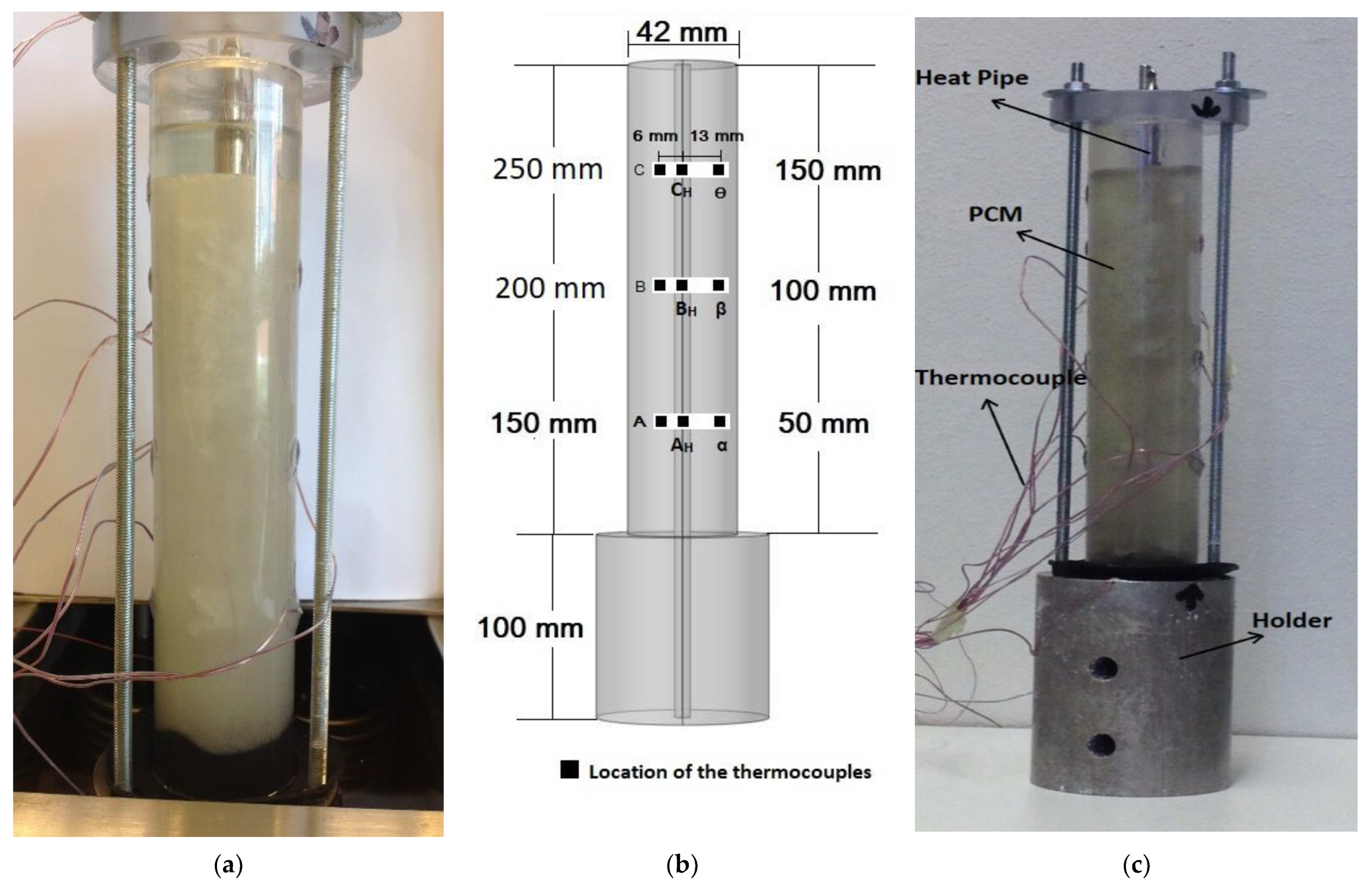
To consider the performance of the heat pipe-assisted PCM storage system, an experimental test rig was built. The schematic of the setup and the illustration of the actual structure are shown in Figure 1a,b, respectively. The test rig comprised a transparent glass cylinder with an inner diameter and height of 42 mm and 190 mm. A cylindrical aluminum block with a diameter of 70 mm and a height of 100 mm with a hole diameter of 25 mm, and a height of 97 mm drilled from the bottom was selected as a holder. The holder was placed in the source with a constant temperature bath.
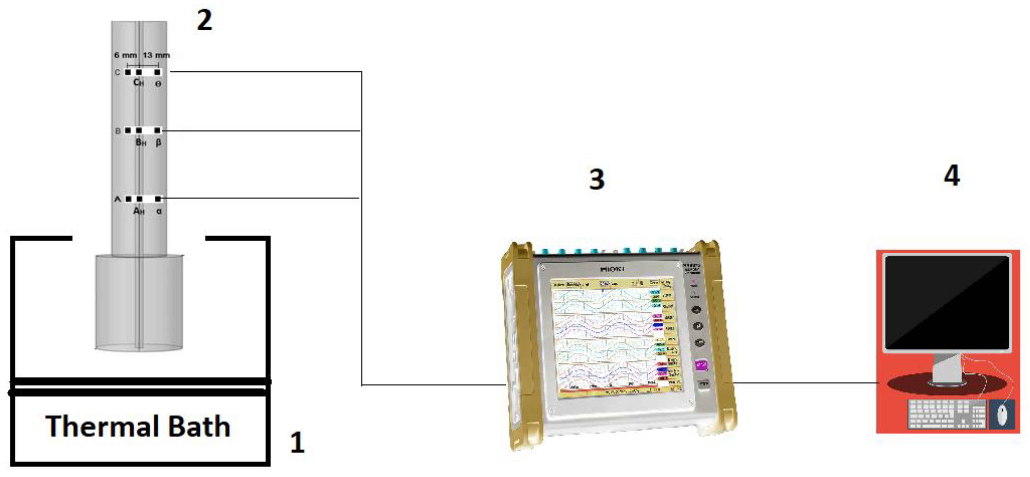
A length of 190 mm of the heat pipe was put inside the PCM cylinder and the remaining (100 mm) was exposed to the thermal bath at a constant temperature. The plastic washer was used to control the leaks. The top of the cylinder was enclosed with a lid with a hole for adding the PCM. The storage and the lid were connected to the block by three long pins. A thermal insulation cover was used to insulate the PCM storage to minimize ambient heat transfer. Figure 2 displays the schematic of the test setup. A cylindrical copper heat pipe with distilled water as a working fluid was used to perform the experiment. Table 1 represents the main features of the heat pipe.
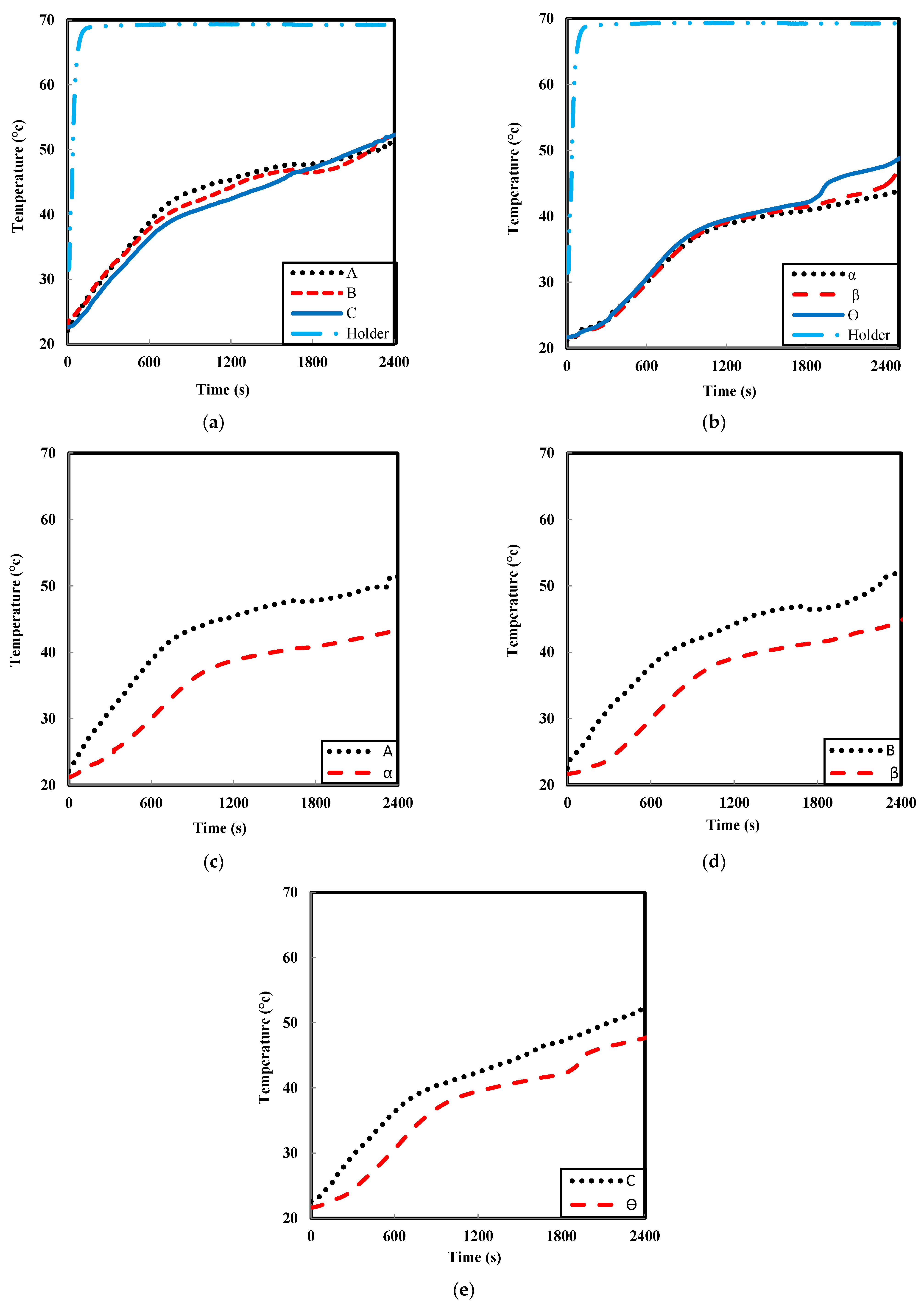
A total of eleven K-type thermocouples were utilized to record all temperatures. In order to record the temperature at a different location of the PCM, six thermocouples were attached in a radius of 6 mm and 13 mm from the center of the cylinder and heights of 50 mm, 100 mm, and 150 mm of PCM cylinder. Thermocouples A, B, and C were placed for the radius of 6 mm and α, β, and θ for the radius of 13 mm for mentioned heights. In addition, three thermocouples were attached on the surface of the heat pipe at heights of 50 mm, 100 mm, and 150 mm, which have been specified by AH, BH, and CH. Holder constant temperature was measured by the average of two thermocouples attached to the holder. All thermocouples were cautiously calibrated, and the expected error of temperature was ±0.2 °C.
The melting process has been measured for 50 °C, 60 °C, and 70 °C temperatures. The experiments were limited to a single PCM (RT42) from Rubitherm Company. A number of essential properties of RT42 are provided in Table 2.
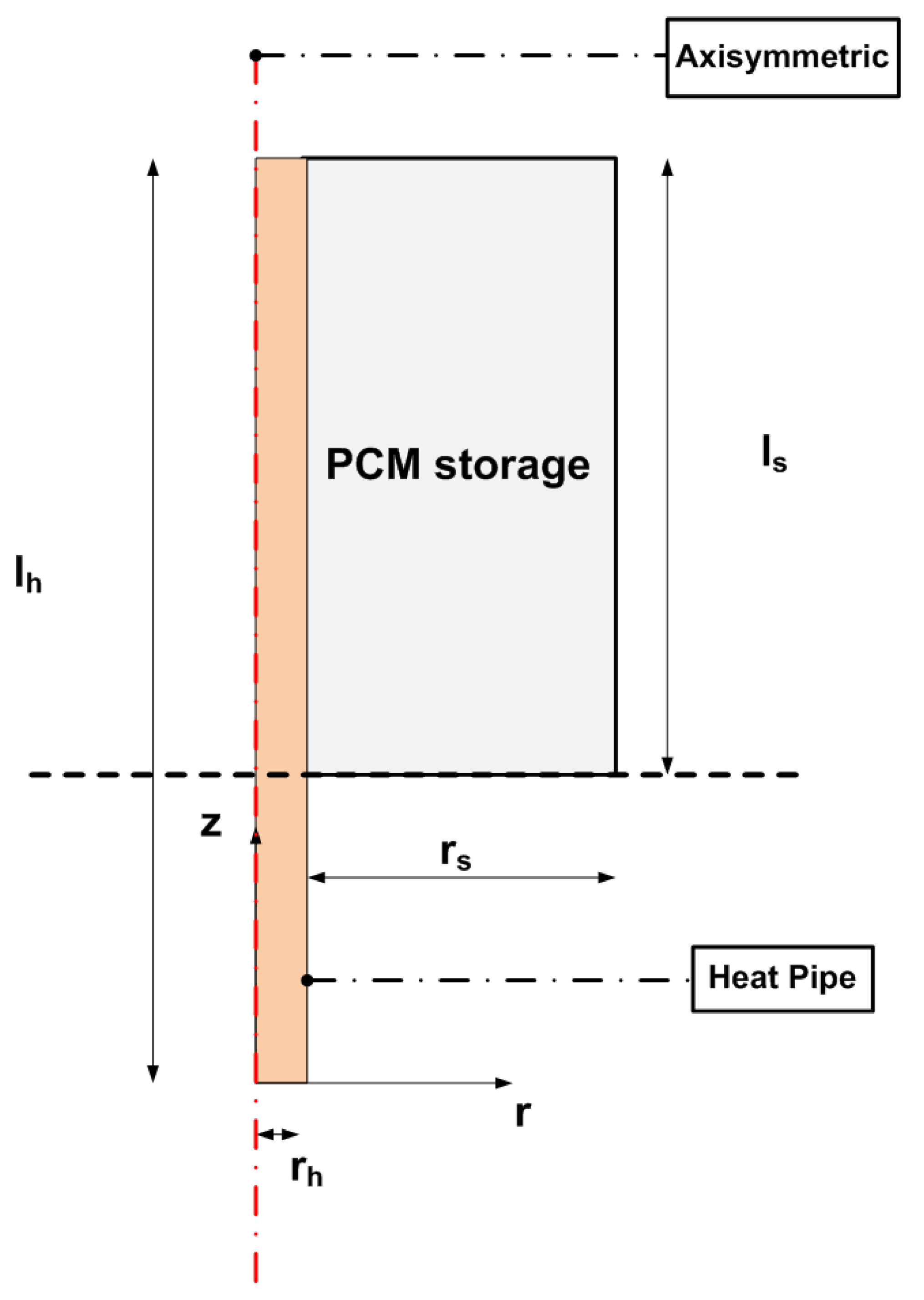
Physical Model
As shown in Figure 3, the system consisted of a cylindrical heat pipe and PCM storage that covered 190 mm of the heat pipe. The storage part was filled with RT42 as PCM. The radius and length of PCM storage were 21 mm (rs) and 190 mm (ls), respectively. Additionally, the radius and length of the heat pipe were 3 mm (rh) and 290 mm (lh), respectively.
3. Experimental Results and Discussion
3.1. Performance of the Heat Pipe
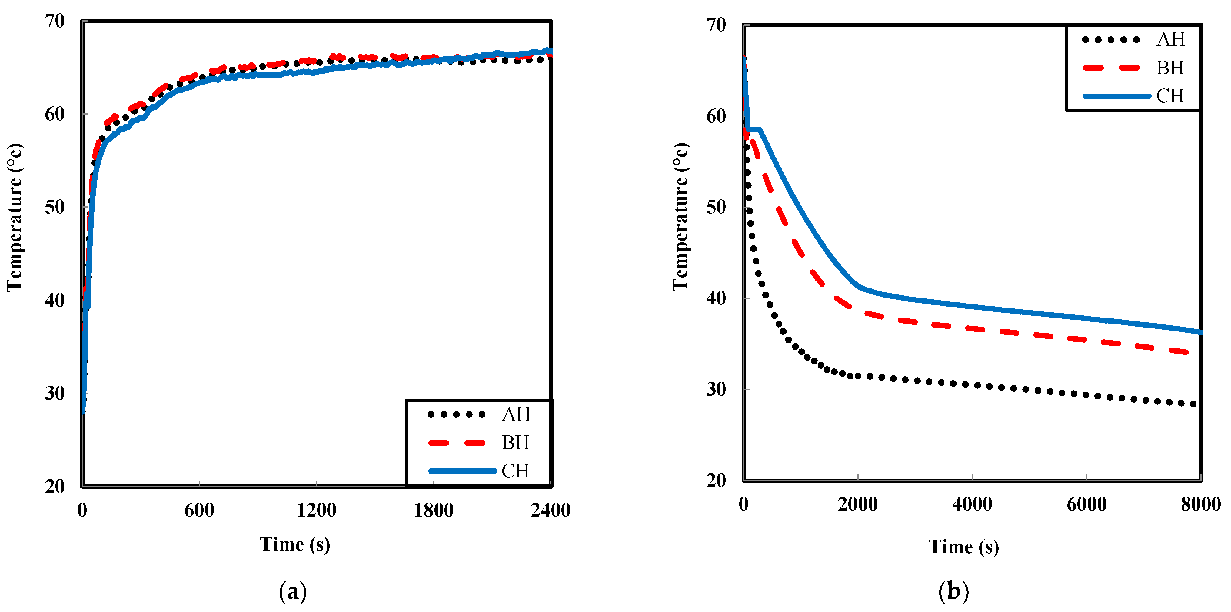
The heat pipe as a super heat conductor can transfer heat with high efficiency. Figure 4a describes the temperature variation of the heat pipe in a constant hot temperature of the bath. In the charging process, the bath temperature provided a constant 70 °C, whereas the PCM storage had a temperature of 23 °C. On the other hand, Figure 4b presents the wall temperatures of the heat pipe with a constant cold temperature of the bath. In the discharging process, the PCM was fully charged (70 °C), whereas the thermal bath was set at 23 °C. According to Figure 4a, at the beginning of the charging process, the heat pipe wall temperature increased rapidly due to its high thermal conductivity. Thus, it can explain the rapid rise of the heat pipe wall temperature during this step. However, as soon as the wall temperature of the heat pipe was more than the PCM phase change temperature, heat was transferred to the PCM through pure conduction. Therefore, the temperature rise rate slowed as the process continued. Figure 4b represents the discharging process. At the beginning of the process, the heat pipe wall cooled very quickly and transferred the heat from the PCM to cold water. Some non-uniformity can be seen in the heat pipe surface temperature during the discharging process. In this manner, the temperature gradient was low on the surface of the heat pipe. However, the heat pipe working flow had to flow against gravity because the condenser part of the heat pipe was located in the bath.
3.2. Charging Curves and Phase Change Interfaces
In order to do the charging test, the PCM storage was filled with liquid PCM several times to confirm the absence of air bubbles. Next, the storage was kept at 23 °C for 24 h to reach the uniform temperature. To start the charging process, the bath temperature was set at 70 °C. Broad experiments were performed to test the performance charging of the PCM storage system embedded with a vertical heat pipe. Therefore, many melting curves of the PCM were obtained.
Figure 5 displays the typical PCM temperatures at different radii of A, B, C, α, β, and θ in the axial direction, which were given in Figure 1, for a bath water temperature of 70 °C. As it can be seen, the phase change happened approximately between t = 600 s to t = 800 s in Figure 5a; however, it happened almost at t = 1000 s in Figure 5b. This phenomenon was more evident in comparison to thermocouples in the radius of 6 mm and 13 mm in Figure 5c–e.
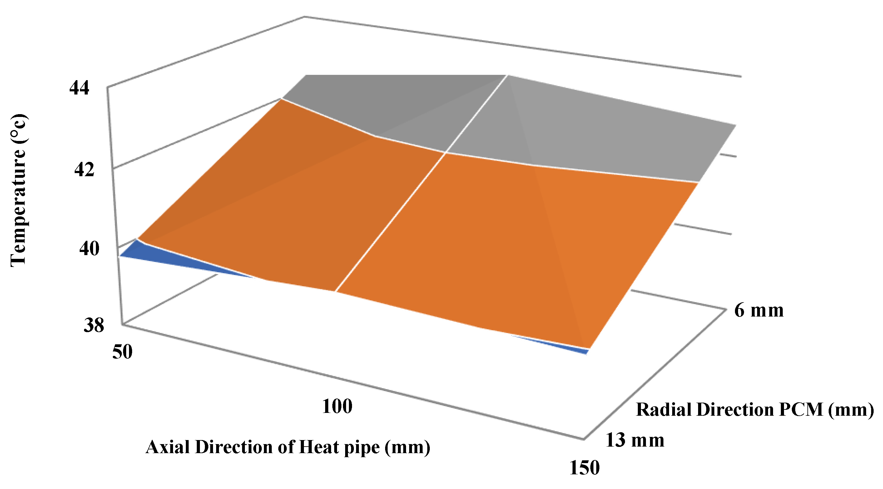
Figure 6 displays the temperature profile of the heat pipe and PCM for the charging process at t = 1200 s. It is obvious that the temperature difference in the axial direction of the heat pipe was less than 0.5 °C, which was tremendously smaller than the radial direction (more than 2 °C). This phenomenon demonstrates high efficiency, excellent temperature leveling ability, and minimal applied heat pipe thermal resistance in the axial direction [51].
3.3. Influences of Increasing Bath Water Temperature
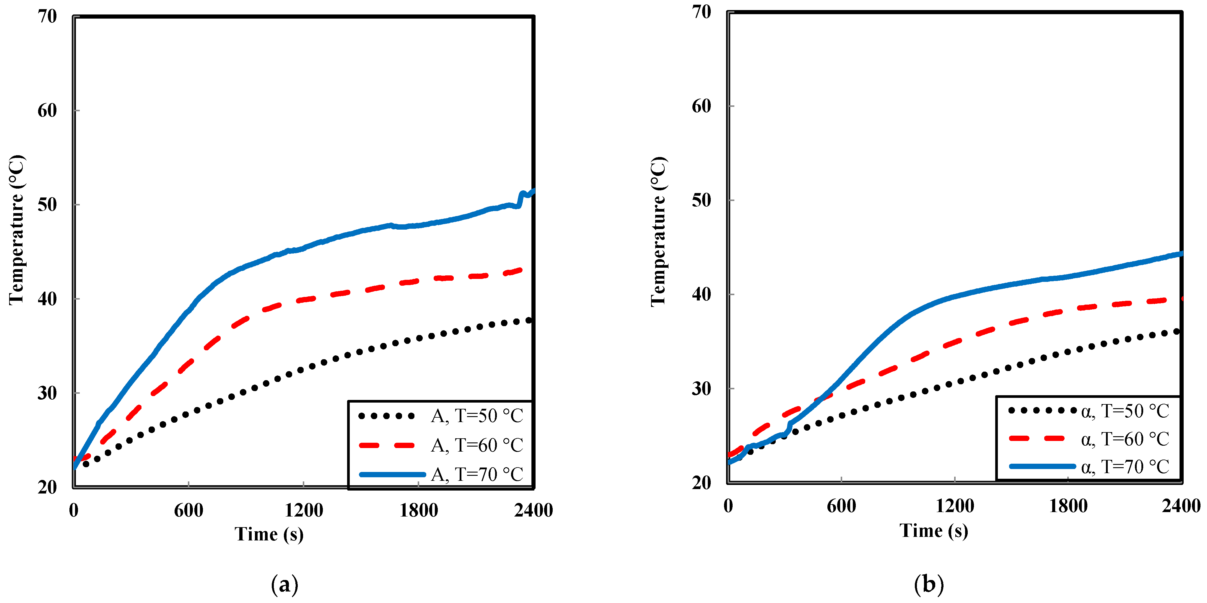
As was expected, the hot water temperature had an imposing effect on the melting operation processes. Therefore, a significant number of experiments were done to study this effect. Figure 7a,b summarizes a number of typical results and shows the effect of hot water temperature on PCM temperature variation.
According to Figure 7, the increasing bath water temperature had a significant and direct influence on PCM temperature. Increasing the water temperature directly affected the inlet temperature of the evaporator, which was influenced by PCM temperature. It is observable that phase change time for the temperature of 70 °C decreased tremendously for both radii. The experimental results in Figure 7 demonstrate that the phase change the time for inlet temperature of 60 °C was less than 1600 s, which reduced to 800 s for 70 °C. On the other hand, the phase change time for a temperature of 50 °C was more than 2400 s.
3.4. Discharging Curves and Phase Change Interfaces
The solidification process is an application of the PCM that results from heat pipe cooling. In this manner, a section of the heat pipe located in the PCM plays the role of the evaporator. The group of solidification curves for different heights and radius can be seen in Figure 8.
According to Figure 8, PCM cooled down and changed from the liquid to the solid state, which represents a normal solidification process. The discharging process was divided into three different areas, which are shown in Figure 8c. In the initial area, heat extracted from the PCM via the heat pipe (1500–2000 s) reached the phase change point. The heat that was absorbed by cold water was mainly the sensible heat of liquid PCM.
Due to the fact that heat storage capacity in the sensible area (1, 3) was really lower than latent heat area (2), the diminishing rate of the PCM temperature was quicker. In the next step, the process entered the second period (2000–6000 s). The temperature of the PCM diminished tremendously slower than in the initial period because of the latent heat effect. Finally, when the solidification of the PCM was complete, again, the heat was extracted as sensible heat from the PCM, which sped up the decline of the PCM temperature.
4. Numerical Modeling
In this study, Fluent 14.5 software was used to simulate the PCM storage system’s temperature distribution and liquid fraction. The geometry of the test setup was drawn in two dimensions and meshed using the Gambit software. The experimental test section was modeled using a 2D axisymmetric geometry. Boundary and initial conditions were defined and transferred into the Fluent software for further process. The liquid fraction and temperature contour of PCM have been described during the melting and solidification processes.
4.1. Descriptive Equations for PCM
The basic and fundamental governing equations for the PCM are divided by the following continuity, momentum, and energy equations [53]:
The scaled temperature of the PCM can be defined as follows:
as a primary temperature, as a phase change temperature, as a final temperature . A phase change (mushy zone) occurs between the solid and liquid zone within the time interval of . The phase of the PCM can be defined as below.
The heat capacity can be defined as a value of phase change function, which depends on the PCM temperature [54]:
The heat that the PCM can absorb is evaluated using the following equation:
In Equation (7), represents the mass of the PCM, while its thermal conductivity can be obtainable as follows:
For the heat pipe simulation, it was replaced by a solid copper, and the effective thermal conductivity of components was used in the simulation [41,42,43,44,55].
4.2. Validation and Verification
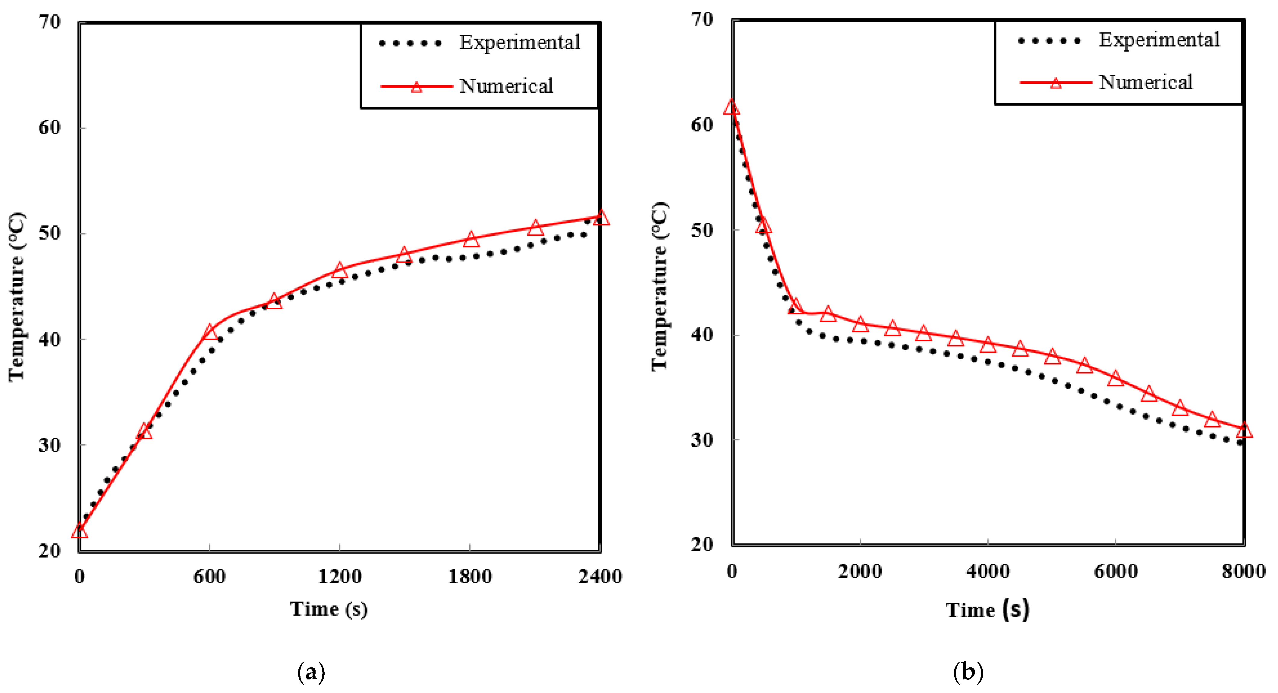
To validate the simulation, the experimental results of the system were compared with the numerical ones. For both charging and discharging modes, the temperatures of PCM versus time were validated with experimental results. Figure 9a,b illustrates the average temperatures of the charging and discharging process versus time. As can be seen, the numerical results had an acceptable agreement with experimental ones.
4.3. Charging Process
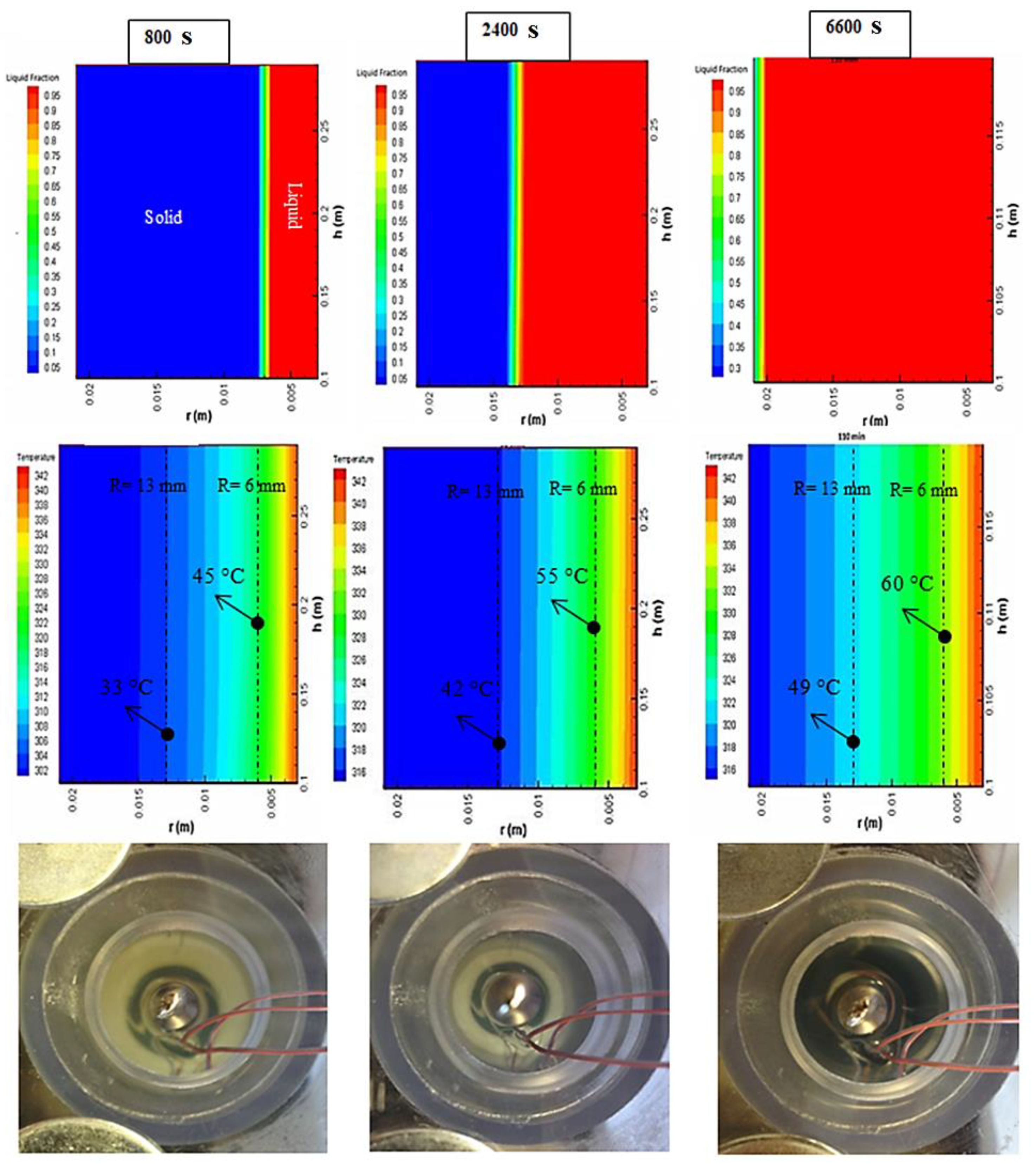
Pictures taken in this configuration were compared with liquid fractions and temperature contours obtained with Fluent in Figure 10.
The PCM first melted surround the heat pipe wall, as expected. At the beginning of the charging process, PCM received the heat as a sensible form, which was mainly used to increase the temperature of the PCM to the phase change temperature. The melting process began when the PCM temperature reached the phase change temperature. First, a thin vertical PCM layer melted along the heat pipe wall from the bottom to the top, as noted in the liquid fraction contour at t = 800 s. As seen in the temperature contour at t = 800 s, the thermocouples in the radius of 6 mm passed the phase change area and reached 45 °C. However, the temperature of the thermocouples in the radius of 13 mm was 33 °C and still is in solid form. At t = 2400 s, thermocouples in a radius of 6 mm reach 55 °C and those in a radius of 13 mm, located in the mushy zone area, reached 42 °C. The mentioned modes are presented in the experimental temperature in Figure 5. Obviously, at t = 800 s, all the thermocouples that were located in radii of 6 mm and 13 mm, were located in a thin layer of melted PCM and solid PCM, respectively. They were approximately at temperatures of 45 °C and 33 °C, respectively. Moreover, at t = 2400 s, all the thermocouples in radii 6 mm and 13 mm were almost at the temperature of 55 °C and 42 °C, respectively.
4.4. Discharging Process
Pictures taken during the discharge process are compared with liquid fraction and temperature contours in Figure 11.
Pictures taken during the discharge process are compared with liquid fraction and temperature contours in Figure 11. The temperature of the cold water was 23 °C. The PCM was heated to a given temperature (70 °C) with hot water in order to prepare the PCM storage for the discharging process. When the whole PCM temperature was steady and uniform, the test rig was put in cold water (23 °C), and the discharging experiment started. The discharging process began when the wall temperature of the heat pipe was equal to or lower than the solidification point. After a while, a thin layer of solid PCM covered the heat pipe wall from the bottom to the top, as noted in the liquid fraction contour at t = 1000 s. As seen in the temperature contour at t = 1000 s, the thermocouples in a radius of 6 mm were almost located in the phase change area (mushy zone) and reached 43 °C. Instead, the temperature of the thermocouples in the radius of 13 mm was 57 °C and they were still in the liquid form. As seen at t = 4200 s, thermocouples in a radius of 6 mm reached 31 °C and radius of 13 mm, located in mushy zone area, reached 40 °C. The mentioned numbers can be proven by the temperature evolution plots in Figure 8. As specified by dashed lines at t = 1000 s, all the thermocouples that were in the 6 mm radius were approximately located in the mushy zone PCM. They were almost at a temperature of 43 °C. Moreover, at t = 4200 s, all the thermocouples in the radii of 6 mm and 13 mm were almost at the temperatures of 57 °C and 40 °C, respectively.
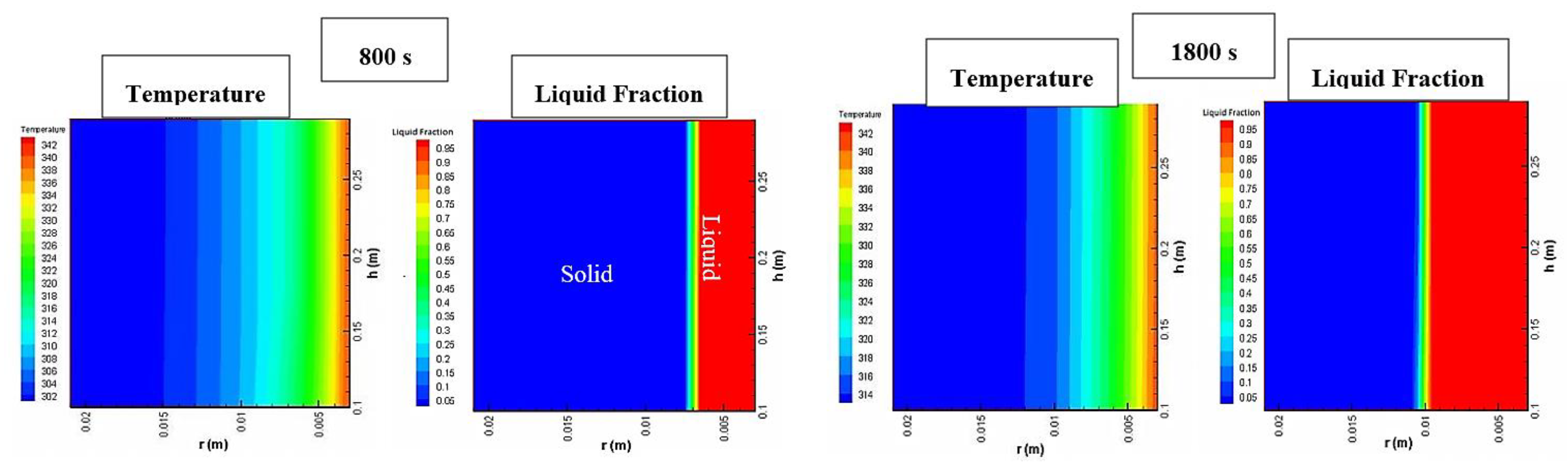
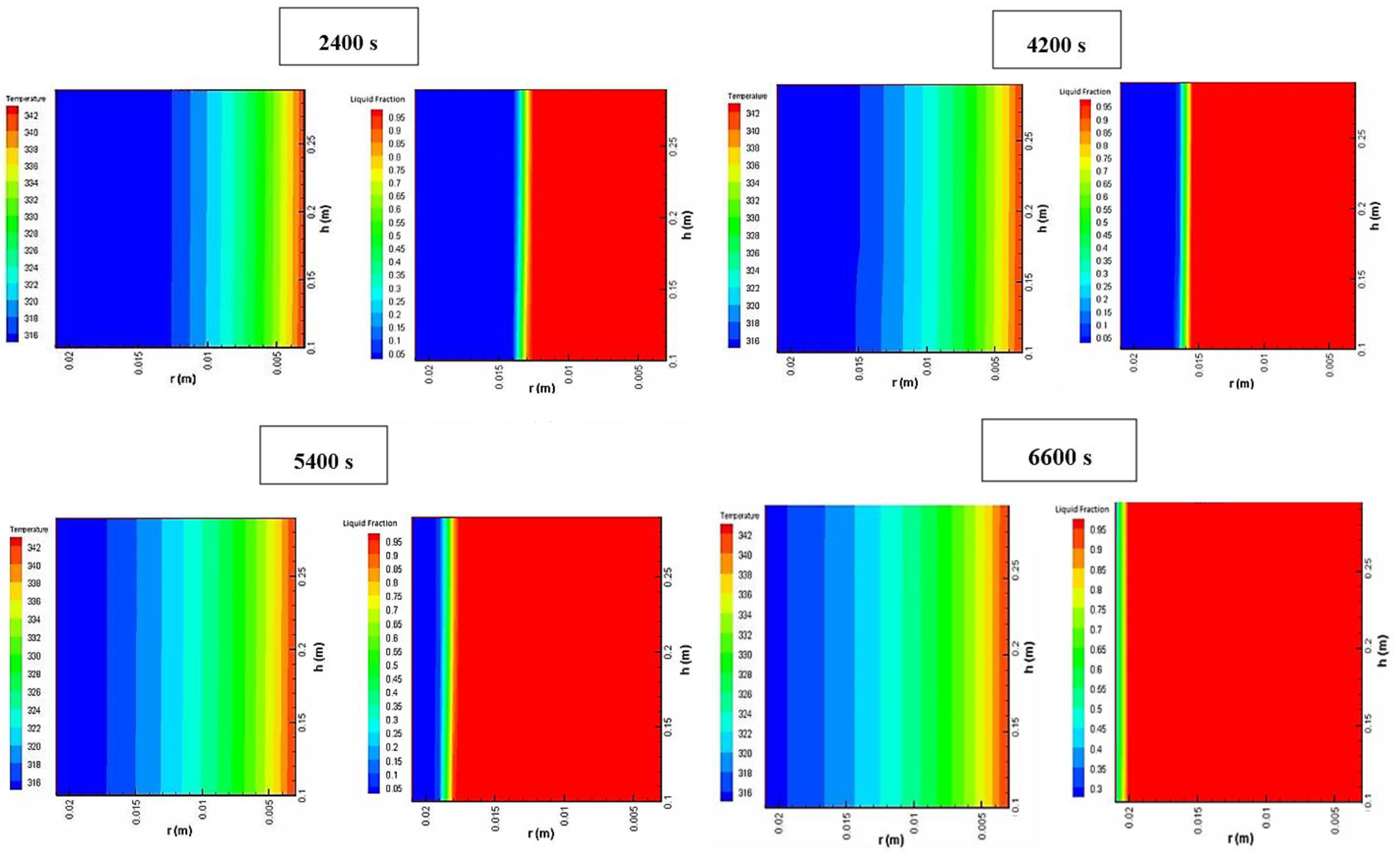
4.5. Temperature and Liquid Fraction Contours during the Charging Process
The PCM’s numerical temperature and liquid fraction contours during the charging process (T = 70 °C) can be seen in Figure 12. The vertical axes show the heat pipe wall (right side) and the horizontal axes show the radius of PCM storage (downside). Thermal transport was happening between the hot water and the liquid surface of the PCM. At the beginning time of the melting process, PCM received the heat via the heat pipe from the hot water in a sensible form. Utilizing this heat, the temperature of PCM gradually increased to the melting point. The melting process started once the wall temperature of the heat pipe was equal to or higher than the melting point of PCM. The heat was transferred to the PCM by pure conduction before melting, and the temperature increased almost linearly with time.
According to the contours in primary time, due to the high efficiency of the heat pipe and low thermal conductivity of PCM, the temperature of the heat pipe increased very quickly. It is noticeable that the temperature rise inside the PCM storage increased with time, and solidified layer thickness of PCM storage decreased. It can be seen that after t = 2400 s, 50% of the PCM temperature was more than the melting point, and finally, at t = 6600 s, the total PCM storage temperature was more than the melting point.
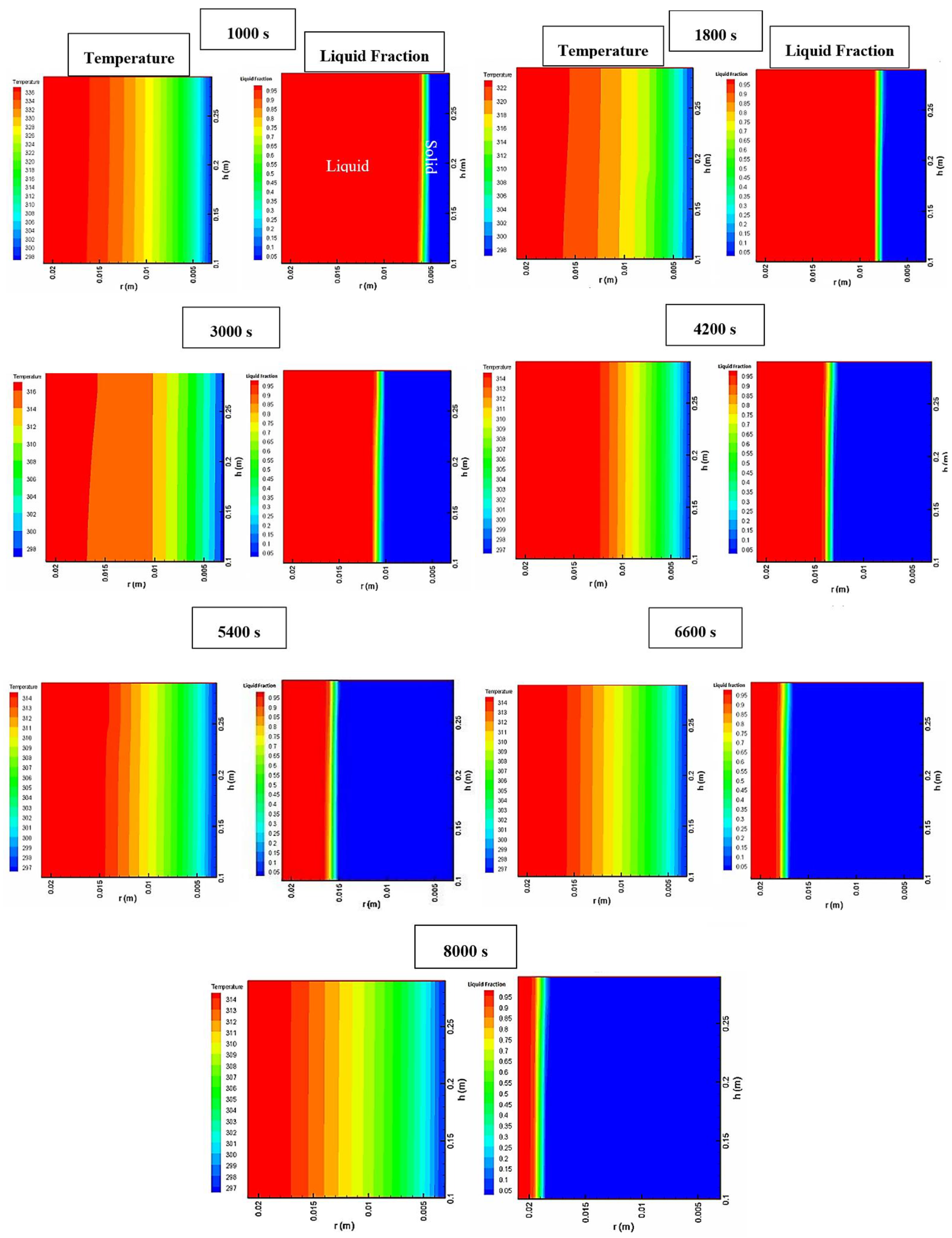
4.6. Temperature and Liquid Fraction Contours during the Discharging Process
Figure 13 depicts the PCM’s numerical temperature and liquid fraction contours during the solidification process (T = 23 °C) from the beginning until the end of the process. Temperatures contours show the solidification process for seven different periods. According to the colors, the solidified and melted parts are defined from the blue to red areas, respectively. Thermal transport occurred at the interface of the liquid surface of the PCM and cooling water bath. According to Figure 13, PCM was cooled from the liquid to the solid state. Utilizing the heat pipe, the temperature of PCM decreased to the solidification point. The solidification process started once the wall temperature of the heat pipe was equal to or less than the phase change temperature of PCM. Temperature decreased inside the PCM storage by increasing the time and solidified layer thickness of PCM increased. It can be seen that more than 50% of PCM was solidified after t = 4200 s and, finally, at t = 8000 s, total PCM temperature was less than phase change temperature.
5. Summary and Outlook
5.1. Conclusions
In this study, a heat-pipe-assisted PCM system was built to improve the rate of energy storage (charging/discharging). Experiments were performed to investigate the thermal behavior of PCM in the presence of the heat pipe. A 2D axisymmetric numerical model was built and validated by experimental data. The following conclusions were drawn.
- The wall temperature profile along the heat pipe length at 100 mm, 150 mm, and 200 mm was experimentally considered in the charging and discharging processes. It was found that the faster temperature changes in the heat pipe may result in higher thermal efficiency.
- The PCM temperature evolutions as a function of the axial position in charging and discharging processes were monitored using the six thermocouples in the radii of 6 mm and 13 mm.
- The influence of the thermal bath temperature (50 °C, 60 °C, and 70 °C) on the phase change time of the PCM has been investigated. It was found that the hotter temperature resulted in lower phase change time.
- The PCM storage picture, liquid fraction, and temperature contour have been compared in different charging and discharging times.
5.2. Future Work
The advantage of using the energy storage embedded with a heat pipe was considered in the present study. Since the heat pipes are gravity-dependent, the heat transfer efficiency of the presented system can be considered in different inclination angles for future studies. Moreover, the role of fin, graphite, nanomaterial, mesh, and so on can be considered to increase the rate of energy storage.
Author Contributions
Conceptualization, formal analysis, investigation, and writing—original journal draft by H.B.; methodology, software, and validation by M.B. (Mohammadreza Behi); review and editing by A.G., D.K., A.A., M.G. and M.B. (Masud Behnia). All authors have read and agreed to the published version of the manuscript.
Funding
This research received no external funding.
Institutional Review Board Statement
Not applicable.
Data Availability Statement
The supporting data will be made available on request.
Conflicts of Interest
The authors declare no conflict of interest.
References
- Corumlu, V.; Ozsoy, A.; Ozturk, M. Thermodynamic studies of a novel heat pipe evacuated tube solar collectors based integrated process for hydrogen production. Int. J. Hydrog. Energy 2018, 43, 1060–1070. [Google Scholar] [CrossRef]
- Behi, H.; Karimi, D.; Jaguemont, J.; Gandoman, F.H.; Khaleghi, S.; van Mierlo, J.; Berecibar, M. Aluminum Heat Sink Assisted Air-Cooling Thermal Management System for High Current Applications in Electric Vehicles. In Proceedings of the 2020 AEIT International Conference of Electrical and Electronic Technologies for Automotive (AEIT AUTOMOTIVE), Turin, Italy, 18–20 November 2020; pp. 1–6. [Google Scholar]
- Karimi, D.; Behi, H.; Hosen, M.S.; Jaguemont, J.; Berecibar, M.; van Mierlo, J. A compact and optimized liquid-cooled thermal management system for high power lithium-ion capacitors. Appl. Therm. Eng. 2021, 185, 116449. [Google Scholar] [CrossRef]
- Karimi, D.; Behi, H.; Jaguemont, J.; El Baghdadi, M.; van Mierlo, J.; Hegazy, O. Thermal Concept Design of MOSFET Power Modules in Inverter Subsystems for Electric Vehicles. In Proceedings of the 2019 9th International Conference on Power and Energy Systems (ICPES), Perth, WA, Australia, 10–12 December 2019. [Google Scholar] [CrossRef]
- Khaleghi, S.; Karimi, D.; Beheshti, S.H.; Hosen, M.S.; Behi, H.; Berecibar, M.; van Mierlo, J. Online health diagnosis of lithium-ion batteries based on nonlinear autoregressive neural network. Appl. Energy 2021, 282, 116159. [Google Scholar] [CrossRef]
- Karimi, D.; Behi, H.; Jaguemont, J.; Berecibar, M.; van Mierlo, J. Investigation of extruded heat sink assisted air cooling system for lithium-ion capacitor batteries. In Proceedings of the International Conference on Renewable Energy Systems and Environmental Engineering, Brussels, Belgium, 18–20 July 2020; Global Publisher: Erfurt, Germany, 2020; pp. 1–6. [Google Scholar]
- Ghezelbash, R.; Farzaneh-Gord, M.; Behi, H.; Sadi, M.; Khorramabady, H.S. Performance assessment of a natural gas expansion plant integrated with a vertical ground-coupled heat pump. Energy 2015, 93, 2503–2517. [Google Scholar] [CrossRef]
- Mirmohammadi, S.A.; Behi, M.; Ghanbarpour, M. Cooling performance study of a novel heat exchanger in an absorption system. Energy Convers. Manag. 2019, 180, 1001–1012. [Google Scholar] [CrossRef]
- Akbarzadeh, M.; Kalogiannis, T.; Jaguemont, J.; Jin, L.; Behi, H.; Karimi, D.; Beheshti, H.; van Mierlo, J.; Berecibar, M. A comparative study between air cooling and liquid cooling thermal management systems for a high-energy lithium-ion battery module. Appl. Therm. Eng. 2021, 198, 117503. [Google Scholar] [CrossRef]
- Karimi, D.; Behi, H.; Akbarzadeh, M.; van Mierlo, J.; Berecibar, M. Holistic 1D Electro-Thermal Model Coupled to 3D Thermal Model for Hybrid Passive Cooling System Analysis in Electric Vehicles. Energies 2021, 14, 5924. [Google Scholar] [CrossRef]
- Liu, Z.; Wang, Z.; Ma, C. An experimental study on heat transfer characteristics of heat pipe heat exchanger with latent heat storage. Part I: Charging only and discharging only modes. Energy Convers. Manag. 2006, 47, 944–966. [Google Scholar] [CrossRef]
- Qu, J.; Zuo, A.; Liu, H.; Zhao, J.; Rao, Z. Three-Dimensional oscillating heat pipes with novel structure for latent heat thermal energy storage application. Appl. Therm. Eng. 2021, 187, 116574. [Google Scholar] [CrossRef]
- Lu, B.; Zhang, Y.; Sun, D.; Yuan, Z.; Yang, S. Experimental investigation on thermal behavior of paraffin in a vertical shell and spiral fin tube latent heat thermal energy storage unit. Appl. Therm. Eng. 2021, 187, 116575. [Google Scholar] [CrossRef]
- Gandoman, F.H.; Behi, H.; Berecibar, M.; Jaguemont, J.; Aleem, S.H.E.A.; Behi, M.; van Mierlo, J. Chapter 16—Reliability evaluation of Li-ion batteries for electric vehicles applications from the thermal perspectives. In Uncertainties in Modern Power Systems; Zobaa, A.F., Abdel Aleem, S.H.E., Eds.; Academic Press: Cambridge, MA, USA, 2021; pp. 563–587. [Google Scholar] [CrossRef]
- Karimi, D.; Khaleghi, S.; Behi, H.; Beheshti, H.; Hosen, M.S.; Akbarzadeh, M.; van Mierlo, J.; Berecibar, M. Lithium-Ion Capacitor Lifetime Extension through an Optimal Thermal Management System for Smart Grid Applications. Energies 2021, 14, 2907. [Google Scholar] [CrossRef]
- Karimi, D.; Behi, H.; Jaguemont, J.; Berecibar, M.; van Mierlo, J. A refrigerant-based thermal management system for a fast charging process for lithium-ion batteries. In Proceedings of the International Conference on Renewable Energy Systems and Environmental Engineering (IRESE2020), Brussels, Belgium, 18–20 July 2020; Global Publisher: Erfurt, Germany, 2020; pp. 1–6. [Google Scholar]
- Karimi, D.; Behi, H.; Jaguemont, J.; Berecibar, M.; van Mierlo, J. Optimized air-cooling thermal management system for high power lithium-ion capacitors. In Proceedings of the International Conference on Renewable Energy Systems and Environmental Engineering (IRESE2020), Brussels, Belgium, 18–20 July 2020. [Google Scholar]
- Pirasaci, T. Investigation of phase state and heat storage form of the phase change material (PCM) layer integrated into the exterior walls of the residential-apartment during heating season. Energy 2020, 207, 118176. [Google Scholar] [CrossRef]
- Karimi, D.; Hosen, M.S.; Behi, H.; Khaleghi, S.; Akbarzadeh, M.; van Mierlo, J.; Berecibar, M. A hybrid thermal management system for high power lithium-ion capacitors combining heat pipe with phase change materials. Heliyon 2021, 7, e07773. [Google Scholar] [CrossRef]
- Behi, H.; Karimi, D.; Gandoman, F.H.; Akbarzadeh, M.; Khaleghi, S.; Kalogiannis, T.; Hosen, M.S.; Jaguemont, J.; van Mierlo, J.; Berecibar, M. PCM assisted heat pipe cooling system for the thermal management of an LTO cell for high-current profiles. Case Stud. Therm. Eng. 2021, 25, 100920. [Google Scholar] [CrossRef]
- Karimi, D.; Behi, H.; Jaguemont, J.; Sokkeh, M.A.; Kalogiannis, T.; Hosen, M.S.; Berecibar, M.; van Mierlo, J. Thermal performance enhancement of phase change material using aluminum-mesh grid foil for lithium-capacitor modules. J. Energy Storage 2020, 30, 101508. [Google Scholar] [CrossRef]
- Karimi, D.; Jaguemont, J.; Behi, H.; Berecibar, M.; van den Bossche, P.; van Mierlo, J. Passive cooling based battery thermal management using phase change materials for electric vehicles. In Proceedings of the EVS33 International Electric Vehicle Symposium, Portland, OR, USA, 14–17 June 2020; The Electric Drive Transportation Association EDTA: Portland, OR, USA, 2020. [Google Scholar]
- Pawar, V.R.; Sobhansarbandi, S. CFD modeling of a thermal energy storage based heat pipe evacuated tube solar collector. J. Energy Storage 2020, 30, 101528. [Google Scholar] [CrossRef]
- Kuravi, S.; Trahan, J.; Goswami, D.Y.; Rahman, M.M.; Stefanakos, E.K. Thermal energy storage technologies and systems for concentrating solar power plants. Prog. Energy Combust. Sci. 2013, 39, 285–319. [Google Scholar] [CrossRef]
- Behi, M.; Mirmohammadi, S.A.; Ghanbarpour, M.; Behi, H.; Palm, B. Evaluation of a novel solar driven sorption cooling/heating system integrated with PCM storage compartment. Energy 2018, 164, 449–464. [Google Scholar] [CrossRef]
- Nkwetta, D.N.; Haghighat, F. Thermal energy storage with phase change material—A state-of-the art review. Sustain. Cities Soc. 2014, 10, 87–100. [Google Scholar] [CrossRef]
- Wu, W.; Zhang, G.; Ke, X.; Yang, X.; Wang, Z.; Liu, C. Preparation and thermal conductivity enhancement of composite phase change materials for electronic thermal management. Energy Convers. Manag. 2015, 101, 278–284. [Google Scholar] [CrossRef]
- Kibria, M.A.; Anisur, M.R.; Mahfuz, M.H.; Saidur, R.; Metselaar, I.H.S.C. A review on thermophysical properties of nanoparticle dispersed phase change materials. Energy Convers. Manag. 2015, 95, 69–89. [Google Scholar] [CrossRef] [Green Version]
- Fleming, E.; Wen, S.; Shi, L.; da Silva, A.K. Experimental and theoretical analysis of an aluminum foam enhanced phase change thermal storage unit. Int. J. Heat Mass Transf. 2015, 82, 273–281. [Google Scholar] [CrossRef]
- Behi, M.; Mirmohammadi, S.A.; Suma, A.B.; Palm, B.E. Optimized Energy Recovery in Line with Balancing of an ATES. In Proceedings of the ASME 2014 Power Conference, Baltimore, MD, USA, 28–31 July 2014. [Google Scholar] [CrossRef]
- Mirmohammadi, S.A.; Behi, M.; Gan, Y.; Shen, L. Particle-shape-, temperature-, and concentration-dependent thermal conductivity and viscosity of nanofluids. Phys. Rev. E. 2019, 99, 43109. [Google Scholar] [CrossRef] [Green Version]
- Behi, H.; Karimi, D.; Youssef, R.; Patil, M.S.; van Mierlo, J.; Berecibar, M. Comprehensive Passive Thermal Management Systems for Electric Vehicles. Energies 2021, 14, 3881. [Google Scholar] [CrossRef]
- Behi, M.; Shakorian-poor, M.; Mirmohammadi, S.A.; Behi, H.; Rubio, J.I.; Nikkam, N.; Farzaneh-Gord, M.; Gan, Y.; Behnia, M. Experimental and numerical investigation on hydrothermal performance of nanofluids in micro-tubes. Energy 2020, 193, 116658. [Google Scholar] [CrossRef]
- Sun, X.; Liu, L.; Mo, Y.; Li, J.; Li, C. Enhanced thermal energy storage of a paraffin-based phase change material (PCM) using nano carbons. Appl. Therm. Eng. 2020, 181, 115992. [Google Scholar] [CrossRef]
- Mirmohammadi, S.; Behi, M. Investigation on Thermal Conductivity, Viscosity and Stability of Nanofluids. Master’s Thesis, Royal Institute of Technology (KTH), Stockholm, Sweden, 2012; p. 140. [Google Scholar]
- Wang, X.-Q.; Yap, C.; Mujumdar, A.S. A parametric study of phase change material (PCM)-based heat sinks. Int. J. Therm. Sci. 2008, 47, 1055–1068. [Google Scholar] [CrossRef]
- Nithyanandam, K.; Pitchumani, R. Computational studies on a latent thermal energy storage system with integral heat pipes for concentrating solar power. Appl. Energy 2013, 103, 400–415. [Google Scholar] [CrossRef]
- Mahdavi, M.; Qiu, S.; Tiari, S. Numerical investigation of hydrodynamics and thermal performance of a specially configured heat pipe for high-temperature thermal energy storage systems. Appl. Therm. Eng. 2015, 81, 325–337. [Google Scholar] [CrossRef]
- Behi, H.; Karimi, D.; Jaguemont, J.; Berecibar, M.; van Mierlo, J. Experimental study on cooling performance of flat heat pipe for lithium-ion battery at various inclination angels. Energy Perspect. 2020, 1, 77–92. [Google Scholar]
- Chaudhry, H.N.; Hughes, B.R.; Ghani, S.A. A review of heat pipe systems for heat recovery and renewable energy applications. Renew. Sustain. Energy Rev. 2012, 16, 2249–2259. [Google Scholar] [CrossRef]
- Behi, H.; Karimi, D.; Behi, M.; Ghanbarpour, M.; Jaguemont, J.; Akbarzadeh Sokkeh, M.; Heidari Gandoman, F.; Berecibar, M.; van Mierlo, J. A new concept of thermal management system in Li-ion battery using air cooling and heat pipe for electric vehicles. Appl. Therm. Eng. 2020, 147, 115280. [Google Scholar] [CrossRef]
- Behi, H. Experimental and Numerical Study on Heat Pipe Assisted PCM Storage System. Master’s Thesis, KTH School of Industrial Engineering and Management, Stockholm, Sweden, 2015. [Google Scholar]
- Behi, H.; Karimi, D.; Behi, M.; Jaguemont, J.; Ghanbarpour, M.; Behnia, M.; Berecibar, M.; van Mierlo, J. Thermal management analysis using heat pipe in the high current discharging of lithium-ion battery in electric vehicles. J. Energy Storage 2020, 32, 101893. [Google Scholar] [CrossRef]
- Behi, H.; Behi, M.; Karimi, D.; Jaguemont, J.; Ghanbarpour, M.; Behnia, M.; Berecibar, M.; van Mierlo, J. Heat pipe air-cooled thermal management system for lithium-ion batteries: High power applications. Appl. Therm. Eng. 2020, 183, 116240. [Google Scholar] [CrossRef]
- Behi, H.; Karimi, D.; Jaguemont, J.; Gandoman, F.H.; Kalogiannis, T.; Berecibar, M.; van Mierlo, J. Novel thermal management methods to improve the performance of the Li-ion batteries in high discharge current applications. Energy 2021, 224, 120165. [Google Scholar] [CrossRef]
- Nithyanandam, K.; Pitchumani, R. Design of a latent thermal energy storage system with embedded heat pipes. Appl. Energy 2014, 126, 266–280. [Google Scholar] [CrossRef]
- Tiari, S.; Qiu, S.; Mahdavi, M. Discharging process of a finned heat pipe-assisted thermal energy storage system with high temperature phase change material. Energy Convers. Manag. 2016, 118, 426–437. [Google Scholar] [CrossRef]
- Liang, L.; Diao, Y.H.; Zhao, Y.H.; Wang, Z.Y.; Chen, C.Q. Experimental and numerical investigations of latent thermal energy storage using combined flat micro-heat pipe array–metal foam configuration: Simultaneous charging and discharging. Renew. Energy 2021, 171, 416–430. [Google Scholar] [CrossRef]
- Wang, J.; Li, Y.; Wang, Y.; Yang, L.; Kong, X.; Sundén, B. Experimental investigation of heat transfer performance of a heat pipe combined with thermal energy storage materials of CuO-paraffin nanocomposites. Sol. Energy 2020, 211, 928–937. [Google Scholar] [CrossRef]
- Mahdaoui, M.; Kousksou, T.; Blancher, S.; Msaad, A.A.; El Rhafiki, T.; Mouqallid, M. A numerical analysis of solid–liquid phase change heat transfer around a horizontal cylinder. Appl. Math. Model. 2014, 38, 1101–1110. [Google Scholar] [CrossRef]
- Zwanzig, S.D.; Lian, Y.; Brehob, E.G. Numerical simulation of phase change material composite wallboard in a multi-layered building envelope. Energy Convers. Manag. 2013, 69, 27–40. [Google Scholar] [CrossRef] [Green Version]
- Rubitherm Technologies GmbH—Imhoffweg 6–12307 Berlin. Available online: https://www.rubitherm.eu/en/index.php/productcategory/organische-pcm-rt (accessed on 26 September 2021).
- Behi, H.; Ghanbarpour, M.; Behi, M. Investigation of PCM-assisted heat pipe for electronic cooling. Appl. Therm. Eng. 2017, 127, 1132–1142. [Google Scholar] [CrossRef]
- Faghri, A.; Cao, Y. A numerical analysis of phase change problem including natural convection. ASME J. Heat Transf. 1990, 112, 812–816. [Google Scholar]
- Ghanbarpour, M.; Khodabandeh, R. Entropy generation analysis of cylindrical heat pipe using nanofluid. Thermochim. Acta 2015, 610, 37–46. [Google Scholar] [CrossRef]
Figure 1.
(a) The picture of testing inside the thermal bath, (b) location of the thermocouples, and (c) picture of the test setup.
Figure 1.
(a) The picture of testing inside the thermal bath, (b) location of the thermocouples, and (c) picture of the test setup.

Figure 2.
Schematic diagram of the experimental system. (1) Water bath, (2) test rig, (3) data logger, and (4) personal computer.
Figure 2.
Schematic diagram of the experimental system. (1) Water bath, (2) test rig, (3) data logger, and (4) personal computer.

Figure 3.
The physical configuration of a PCM storage system embedded with vertical heat pipe.

Figure 4.
The temperature of the heat pipe in different heights during the (a) charging and (b) discharging processes.
Figure 4.
The temperature of the heat pipe in different heights during the (a) charging and (b) discharging processes.

Figure 5.
Scheme of experimental charging temperature evolution plots as a function of the axial position versus time (70 °C), (a) thermocouples in the radius of 6 mm, (b) thermocouples in the radius of 13 mm, (c–e) temperature comparison of the thermocouples in 6 mm and 13 mm.
Figure 5.
Scheme of experimental charging temperature evolution plots as a function of the axial position versus time (70 °C), (a) thermocouples in the radius of 6 mm, (b) thermocouples in the radius of 13 mm, (c–e) temperature comparison of the thermocouples in 6 mm and 13 mm.

Figure 6.
The temperature profile of the heat pipe and PCM at 1200 s in the charging mode (T = 70 °C).
Figure 6.
The temperature profile of the heat pipe and PCM at 1200 s in the charging mode (T = 70 °C).

Figure 7.
Influences of the bathwater temperature on the charging process, T = 50 °C, 60 °C, and 70 °C for (a) Athemocuples in the radius of 6 mm and (b) α thermocouples in the radius of 13 mm.
Figure 7.
Influences of the bathwater temperature on the charging process, T = 50 °C, 60 °C, and 70 °C for (a) Athemocuples in the radius of 6 mm and (b) α thermocouples in the radius of 13 mm.

Figure 8.
Scheme of experimental discharging temperature evolutions plotted as a function of the axial position versus time (23 °C), (a) thermocouples in radius of 6 mm, (b) thermocouples in radius of 13 mm, (c–e) temperature comparison of the thermocouples in 6 mm and 13 mm.
Figure 8.
Scheme of experimental discharging temperature evolutions plotted as a function of the axial position versus time (23 °C), (a) thermocouples in radius of 6 mm, (b) thermocouples in radius of 13 mm, (c–e) temperature comparison of the thermocouples in 6 mm and 13 mm.


Figure 9.
Experimental measurements compare with numerical for (a) charging and (b) discharging process of “A” thermocouple.
Figure 9.
Experimental measurements compare with numerical for (a) charging and (b) discharging process of “A” thermocouple.

Figure 10.
Experimental melting photos (bottom), numerical temperature contour (middle), and numerical liquid fraction in PCM (top) during the charging process (T = 70 °C).
Figure 10.
Experimental melting photos (bottom), numerical temperature contour (middle), and numerical liquid fraction in PCM (top) during the charging process (T = 70 °C).

Figure 11.
Experimental solidification photos (bottom), numerical temperature contour (middle), and numerical liquid fraction in PCM (top) during discharging process (T = 23 °C).
Figure 11.
Experimental solidification photos (bottom), numerical temperature contour (middle), and numerical liquid fraction in PCM (top) during discharging process (T = 23 °C).

Figure 12.
Numerical temperature and liquid fraction contour for charging process (T = 70 °C).


Figure 13.
Numerical temperature and liquid fraction contour for discharging process (T = 23 °C).


Table 1.
The important properties of the heat pipe.
| Parameter | Value |
|---|---|
| Producer | Thermacore Co. |
| Envelope material | Copper |
| Diameter (mm) | 6 |
| Wall thickness (mm) | 1 |
| Working fluid | Water |
| Working temperature (°C) | 0–100 |
| Heat pipe length (mm) | 290 |
| Wick Structure | Screen Mesh |
Table 2.
The important properties of the PCM [52].
Table 2.
The important properties of the PCM [52].
| Parameter | Value |
|---|---|
| Melting area (°C) | 38–43 |
| Heat storage capacity ±7.5% (kJ/kg) | 165 |
| Specific heat capacity (kJ/kg.K) | 2 |
| Density solid (at 15 °C) (kg/L) | 0.88 |
| Density liquid (at 80 °C) (kg/L) | 0.76 |
| Heat conductivity (both phases) (W/m.K) | 0.2 |
Publisher’s Note: MDPI stays neutral with regard to jurisdictional claims in published maps and institutional affiliations. |
© 2021 by the authors. Licensee MDPI, Basel, Switzerland. This article is an open access article distributed under the terms and conditions of the Creative Commons Attribution (CC BY) license (https://creativecommons.org/licenses/by/4.0/).
Share and Cite
MDPI and ACS Style
Behi, H.; Behi, M.; Ghanbarpour, A.; Karimi, D.; Azad, A.; Ghanbarpour, M.; Behnia, M. Enhancement of the Thermal Energy Storage Using Heat-Pipe-Assisted Phase Change Material. Energies 2021, 14, 6176. https://doi.org/10.3390/en14196176
AMA Style
Behi H, Behi M, Ghanbarpour A, Karimi D, Azad A, Ghanbarpour M, Behnia M. Enhancement of the Thermal Energy Storage Using Heat-Pipe-Assisted Phase Change Material. Energies. 2021; 14(19):6176. https://doi.org/10.3390/en14196176
Chicago/Turabian StyleBehi, Hamidreza, Mohammadreza Behi, Ali Ghanbarpour, Danial Karimi, Aryan Azad, Morteza Ghanbarpour, and Masud Behnia. 2021. "Enhancement of the Thermal Energy Storage Using Heat-Pipe-Assisted Phase Change Material" Energies 14, no. 19: 6176. https://doi.org/10.3390/en14196176
Note that from the first issue of 2016, this journal uses article numbers instead of page numbers. See further details here.