
Dual Active Bridge as a DC Link Current Pulsation Compensator in Energy Storage Applications


Department of Electrical Drives and Machines, Faculty of Electrical Engineering and Computer Science, Lublin University of Technology, 20-618 Lublin, Poland
*
Author to whom correspondence should be addressed.
Energies 2021, 14(19), 6141; https://doi.org/10.3390/en14196141
Submission received: 29 July 2021
/
Revised: 5 September 2021
/
Accepted: 23 September 2021
/
Published: 27 September 2021
(This article belongs to the Special Issue Power Electronics in Renewable, Storage, and Charging Systems)
Abstract
:This paper presents a system for compensating DC link current pulsation in four-wire inverters with energy storage operating under unbalanced load conditions. This phenomenon occurs when an inverter with an independent power control in each of the phases attempts to locally balance the voltage imbalance in the grid. Such a condition creates a DC link current pulsation, which is destructive for energy storage connected to the DC link. The conditions when this situation appears are presented in detail in the paper. A solution to this problem is proposed in the form of a dual active bridge converter and a capacitor bank to actively compensate this pulsation. The control algorithm is proposed based on a proportional-resonant controller. This paper presents the technical background and method by which the controller parameters were calculated, implemented and tested in a real-time system. The test results are presented and discussed, concluding that the proposed solution is an attractive option for protecting the energy storage from DC link current pulsation. The dual active bridge converter combined with resonant controller can compensate the DC link current pulsation almost entirely.
1. Introduction
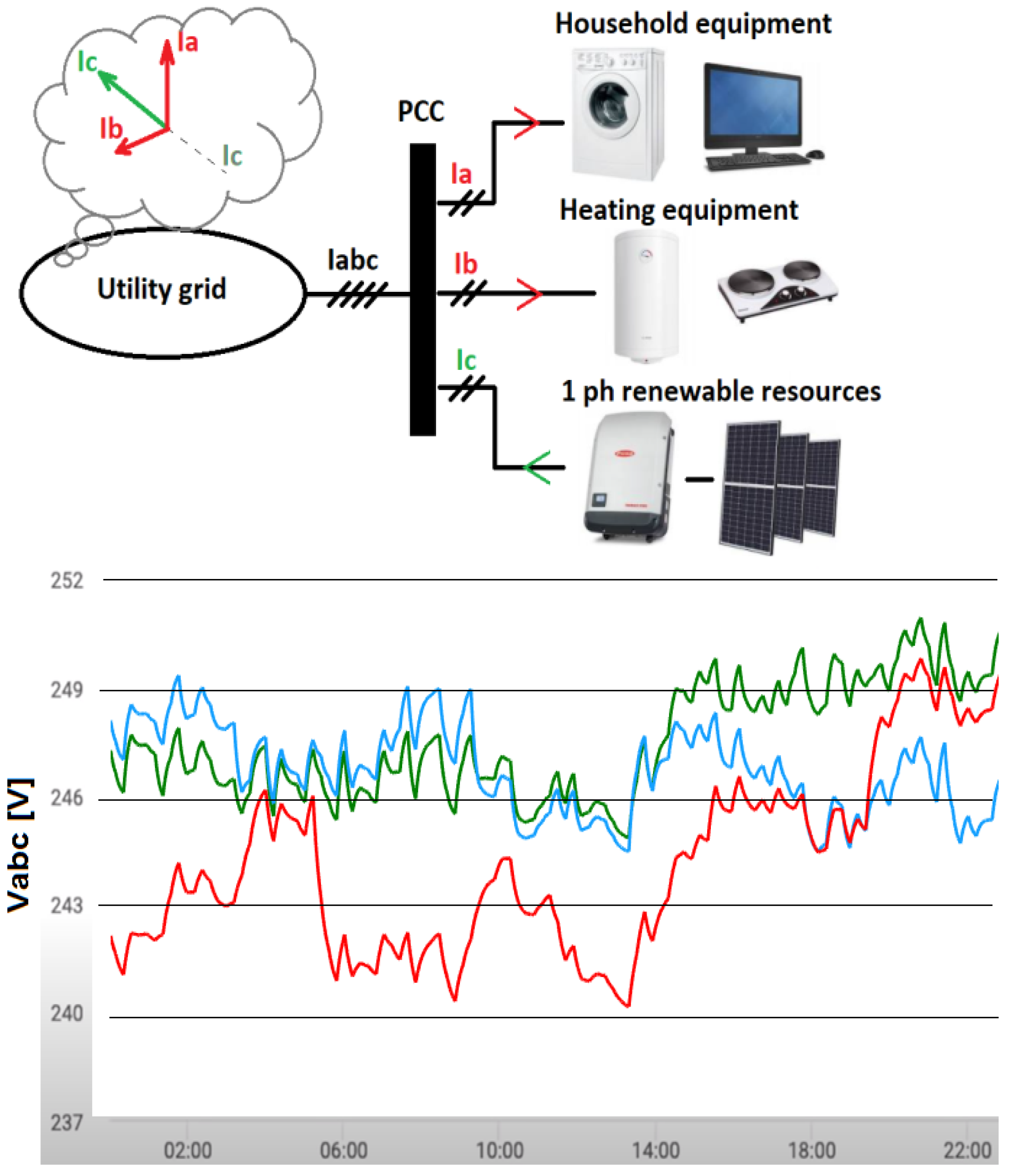
A significant increase in renewable energy sources installed in households has been observed in the past few years. Instead of only consuming energy, the households become prosumers—entities that both produce and consume energy. Additionally, the number of receiving devices increases as well, including pulse power supply-based ones. This may create the problem of a grid load imbalance, and further—a grid voltage imbalance, which can then lead to the local power transformer operating in non-nominal conditions, increasing fault risk and reducing its lifespan. With both pulse loads and renewables present in the grid, the worst-case scenario would mean an overvoltage in one phase and undervoltage in another phase of a three-phase system (Figure 1). The easiest solution to this problem would be to reduce the power output of the household renewables—but that method creates losses, and renders the renewables partially pointless.
There are other methods of solving the grid unbalance problem, mainly based on Dual Vector Current Control methods and three-phase, four-wire inverters [1,2,3]; however, while these methods still generate balanced currents and voltages and can maintain the operation of the grid, they have no means of compensating the imbalance.
In order to be able to locally balance the power flow in the grid, a solar inverter must be equipped with energy storage. The inverter in this situation should have independent control over power in each of the phases, effectively working as three single-phase inverters [4,5]. Utilizing the energy storage as a buffer for grid imbalance compensation creates the problem of an AC current component appearing in a DC link between the inverter and the energy storage. This AC component creates losses in the electrochemical energy storage and causes it to heat up. This phenomenon is utilized in a controlled way in electric vehicles—low AC current is used to pre-heat the batteries when the ambient temperature is too low for the charging process [6,7]. Higher AC components can cause the battery to overheat and the BMS (battery management system) to interrupt the operation of the storage in order to prevent potential damage. Additionally, this process accelerates the aging of the electrochemical energy storage, so it is imperative to minimize this effect. The most common approach to DC link pulsation reduction is to limit the inverter current asymmetry to a level tolerated by the energy storage. Another method would be adding an additional DC/DC converter in parallel to the DC interface of the inverter—e.g., a non-isolated buck-boost converter with a capacitor energy storage. These methods, however, do not guarantee optimal operation of the inverter and energy storage. In this study, a dual active bridge (DAB) topology with supercapacitor was proposed as a solution for the DC link current pulsation problem. This solution increased the dynamics of the system due to the dynamics of the DAB converter itself. Additionally, using isolated topology allowed the implementation of a transformer with optimal voltage ratio for better utilization of the supercapacitor in applications with high voltage DC links. Furthermore, we present herein a novel control algorithm that compensates the current pulsations in DC link, based on proportional-resonant regulators. Using the proportional-resonant controllers and the DAB converter allows compensation of almost all AC pulsation in the DC link, even in cases of high asymmetry operation in the inverter.
2. DC Link Pulsation in a Four-Wire Multi-Resonant Inverter
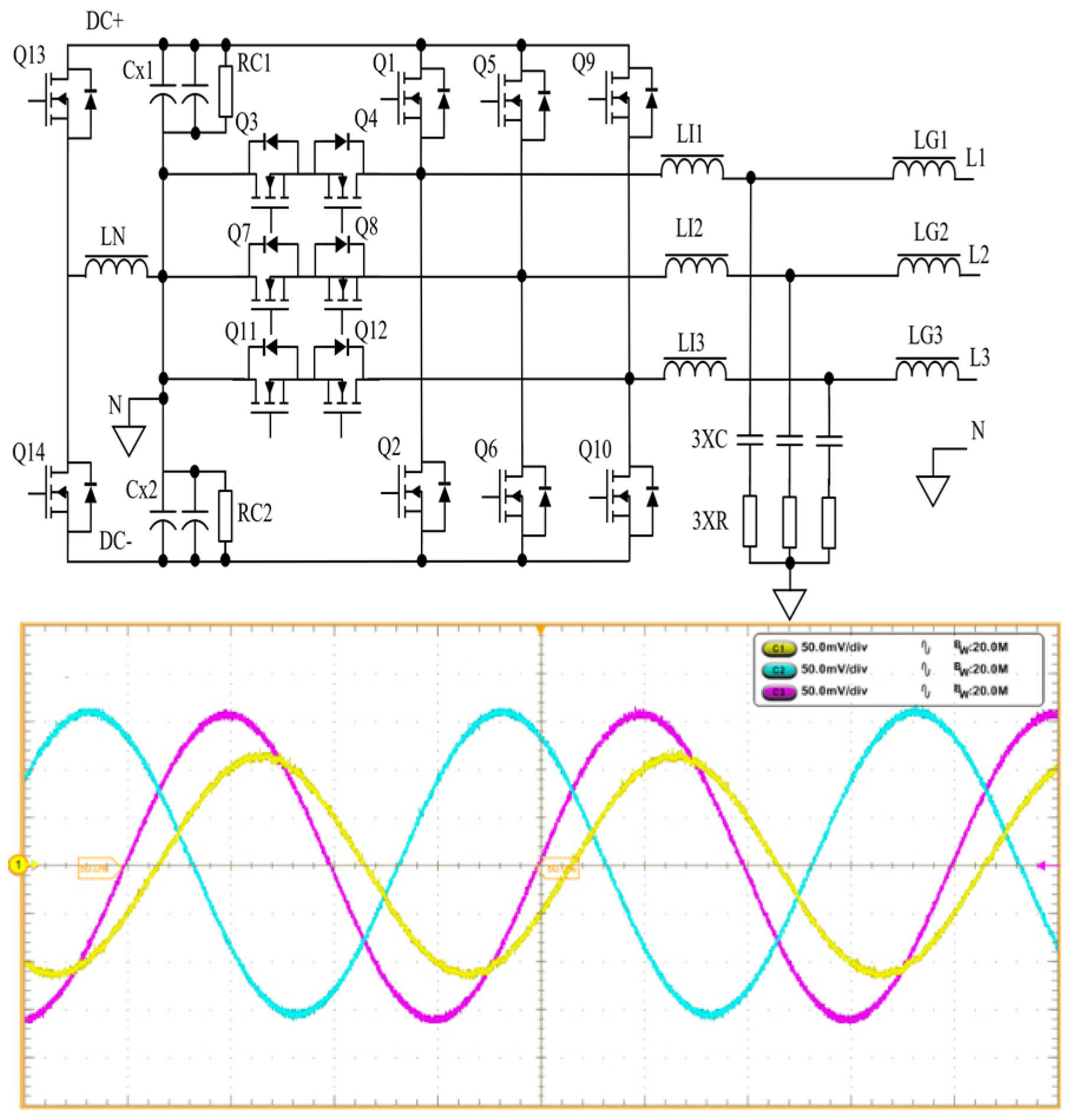
As mentioned in the previous section, a DC link pulsation would occur in an inverter operating with unbalanced currents: for example, when one phase is drawing energy from the grid, one is idle and one is delivering energy to the grid. Another such scenario would be realized when two phases were delivering active power and a single-phase were delivering reactive power to the grid. This kind of operation is possible only in four-wire systems with independent power control in each of the phases. The system presented in (Figure 2) is considered as three separate single-phase inverters.
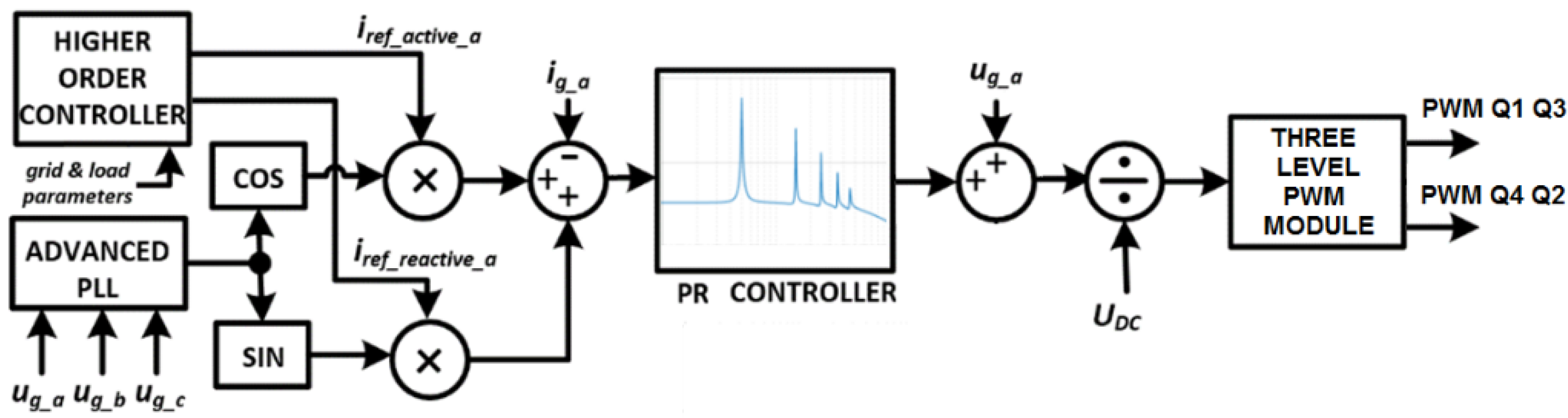
Three separate current reference signals are set by an external controller (local grid operator) in order to compensate grid voltage unbalance (Figure 3). These signals are used to generate sine and cosine signals based on a sawtooth signal generated from a robust synchronization algorithm, for example DDSRF-PLL (Decoupled Double Reference Frame—Phase Locked Loop) [8,9].
The synchronization algorithm is required to operate under asymmetric conditions, which is why basic algorithms would not work. Sinusoidal references are compared against measurements, and an error is passed to resonant controllers, with resonant frequencies matching the main frequency of the grid and its harmonics. Resulting power output to the grid can be described as:
where: p3f—power in DC link, Vk—phase voltage magnitude, Ik—phase current magnitude, ϕvk—phase voltage angle, ϕik—phase current angle.
If the efficiency of the inverter is omitted, then Equation (1) can be used to approximate power output in the DC Link. When the inverter operates with symmetric currents, the sum of time-variant components of three phases is equal to zero, and there is no pulsation in the DC link. When asymmetry is introduced, for example, one phase starts drawing energy from the grid, while two others deliver energy to it, the sum of the time-variant components does not equal zero, and resulting power pulsation appears in the DC link. The frequency of this pulsation is double the frequency of the main grid voltage component.
The magnitude of the AC component of the DC link current (IAC_DCLink) as a function of the magnitude of the AC component of the neutral wire current (In) can be described as:
where: V1—phase RMS voltage, VDC—DC link voltage.
Instantaneous value of the AC component, based on Equations (1) and (3) can be described as:
where ϕn—phase of neutral wire current.
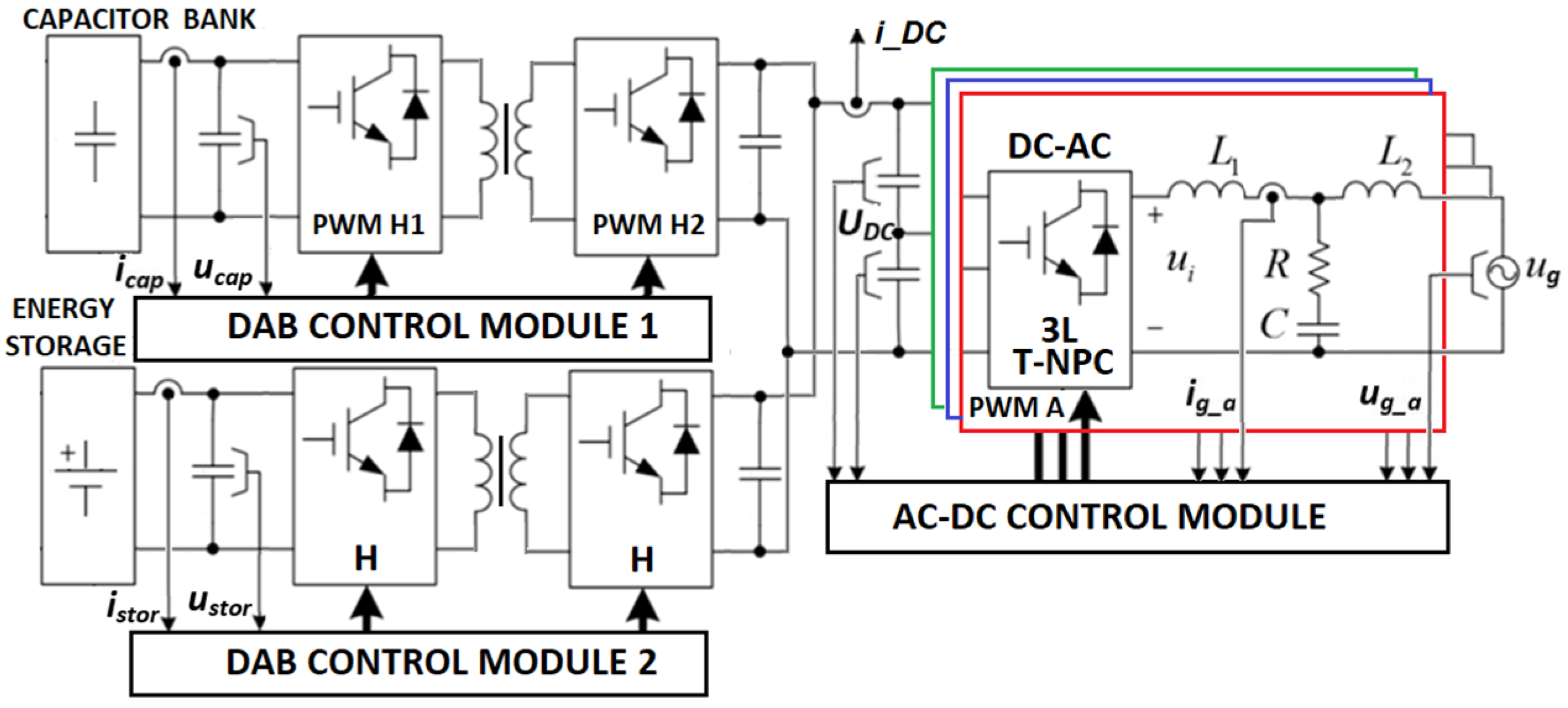
This AC component of the DC link current is a problem for energy storage applications: it can be ignored in applications without an electrochemical energy storage, but at the same time, those applications cannot locally balance any grid unbalances. It can be reduced by increasing the capacitance of the DC link—but a 10 times increase in capacitance will reduce the pulsation only by 20%. A promising solution is presented in (Figure 4), where there are two energy storages connected in parallel: a main electrochemical energy storage connected via isolated DC/DC converter to DC link, and an auxiliary energy storage in the form of a supercapacitor, connected via another isolated DC/DC converter to the same DC link. The DC/DC converter connected to electrochemical energy storage serves as charging and discharging interface, maintaining DC components of the DC link, while the other DC/DC converter is meant to take over any pulsation created by an unbalanced operation mode. Since the AC component requires the converter to switch between charging and discharging at a rate of 100 Hz, the DC/DC converter must possess high dynamics. One of the best solutions in this case is dual active bridge topology (DAB) [8,9], which can smoothly transition between charging and discharging mode. The proposed topology and control algorithm are described in the following section.
3. Dual Active Bridge as a DC Link Current Pulsation Compensator
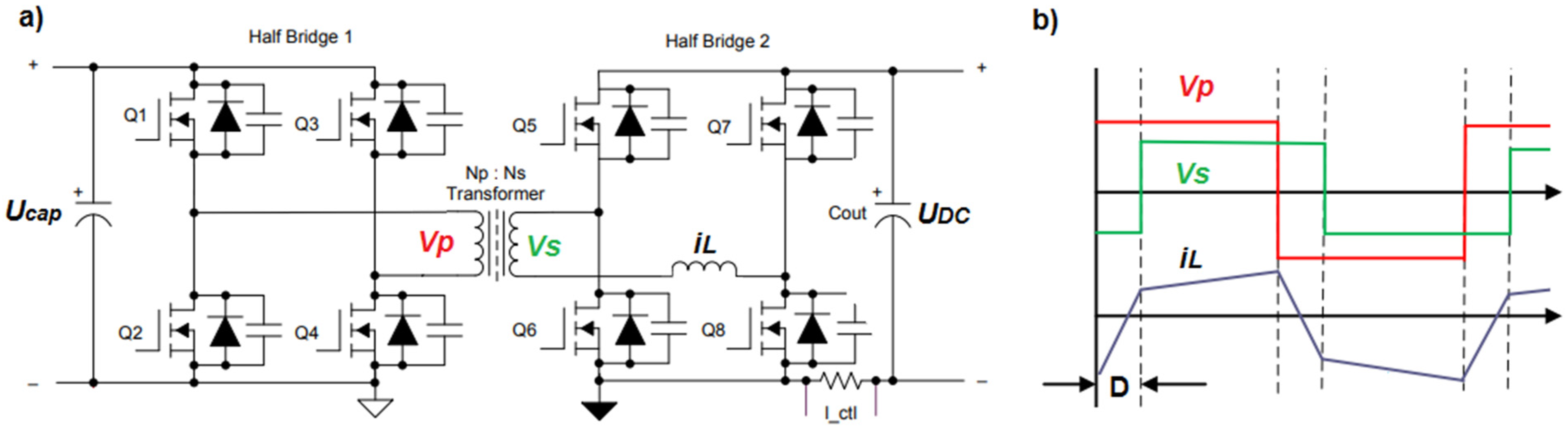
Dual Active Bridge (DAB) topology is the most popular topology in bidirectional electric vehicle charger applications. This type of converter serves as the main charging controller, controlling both charging current and voltage. It has also gained popularity in power distribution, especially in the field of solid-state transformers [10,11]. The main advantage of this topology is that it is fully symmetric (Figure 5) and it can transition between charging and discharging an electric vehicle without any change in the control algorithm: the same algorithm can be used in both cases. Over the years several control schemes for DAB converters were developed, extending the number of degrees of freedom [12,13,14], which are utilized to increase efficiency, reduce circulating currents, etc. In this application, two DAB converters are used as interfaces between the DC link, the energy storage and the capacitor bank. The DAB converter, connected to an electrochemical energy storage, operates as a standard DC current charging controller, based on the DC link state. It operates in a single-phase shift mode, and uses a dual phase shift mode during precharge. The converter when connected to a supercapacitor operates in a different manner: single-phase shift during normal operation, and as phase-shifted full bridge with passive rectification during precharge. This approach allows the converter to build the voltage on the supercapacitor without putting high current stress on semiconductors for the period of precharging the capacitance.
Several works describe the dynamics of the dual active bridge with varying complexity. The most common approach used small signal modeling and a state-space approach to describe the system as MIMO [15,16,17] with 2, 3, 4 and 5 state variables. For the application presented in this paper a linearized description is sufficient [18]. Linearized, small signal transfer function of the DAB converter is described as:
where: Vd—DC link voltage, Llk—equivalent leakage inductance, Ts—switching period, D—phase shift (per unit), Zo—filter impedance. The component directly describes the relation between the current id and phase shift D. This relation is valid and any delays can be neglected, provided the frequencies are at least an order of magnitude lower than the switching frequency.
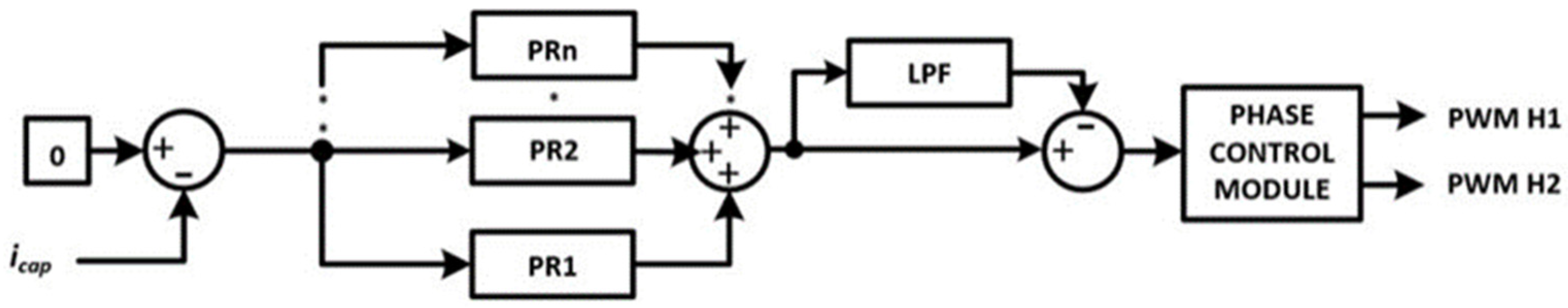
The presented application of the DAB converter aimed to compensate a 100 Hz AC current appearing in the DC link of an inverter operating with unbalanced phase loads. A control algorithm was proposed as depicted in (Figure 6). This algorithm was based on a group of parallel resonant controllers [19]. The first resonant controller was tuned for 100 Hz; additional controllers were required when operating under island conditions. A low pass filter was present (LPF) in the system, to filter out any DC components present in the feedback (icap). The mathematical description of this algorithm is as follows:
where —resonant controller gain, —resonant span parameter, —controller resonant pulsation, —proportional controller gain.
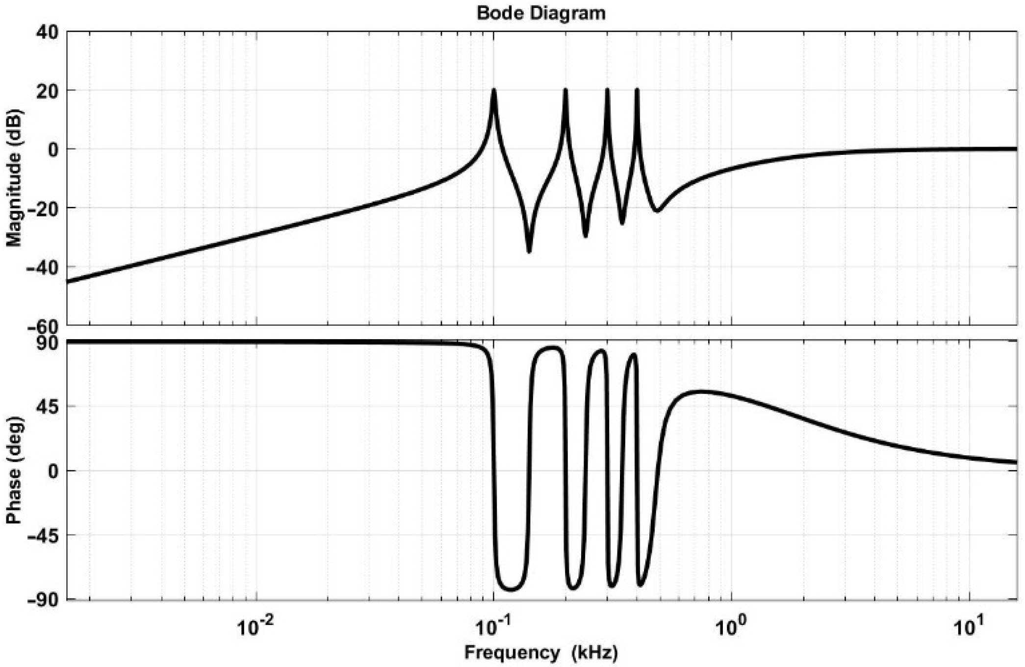
Since this system had high rejection of any DC components (Figure 7) it also prevented the capacitor bank from overcharging or completely discharging.
4. Results
The algorithm for compensating the current pulsation was implemented on a Texas Instruments F28379D Delfino microcontroller. The current was measured on the output of the DAB converter connected to the electrochemical energy storage using Hall sensor. The placement of this measurement allowed the reference signal of the compensator to be zero, and the energy storage current became the feedback. An alternative approach, where current measurement was placed in the main DC link, would require the measured current to become the reference, and the DAB output current would then become the feedback of the control algorithm. The parameters of the resonant compensator were tuned to compensate for the main frequency of the pulsation—100 Hz. Table 1 presents the compensator parameters.
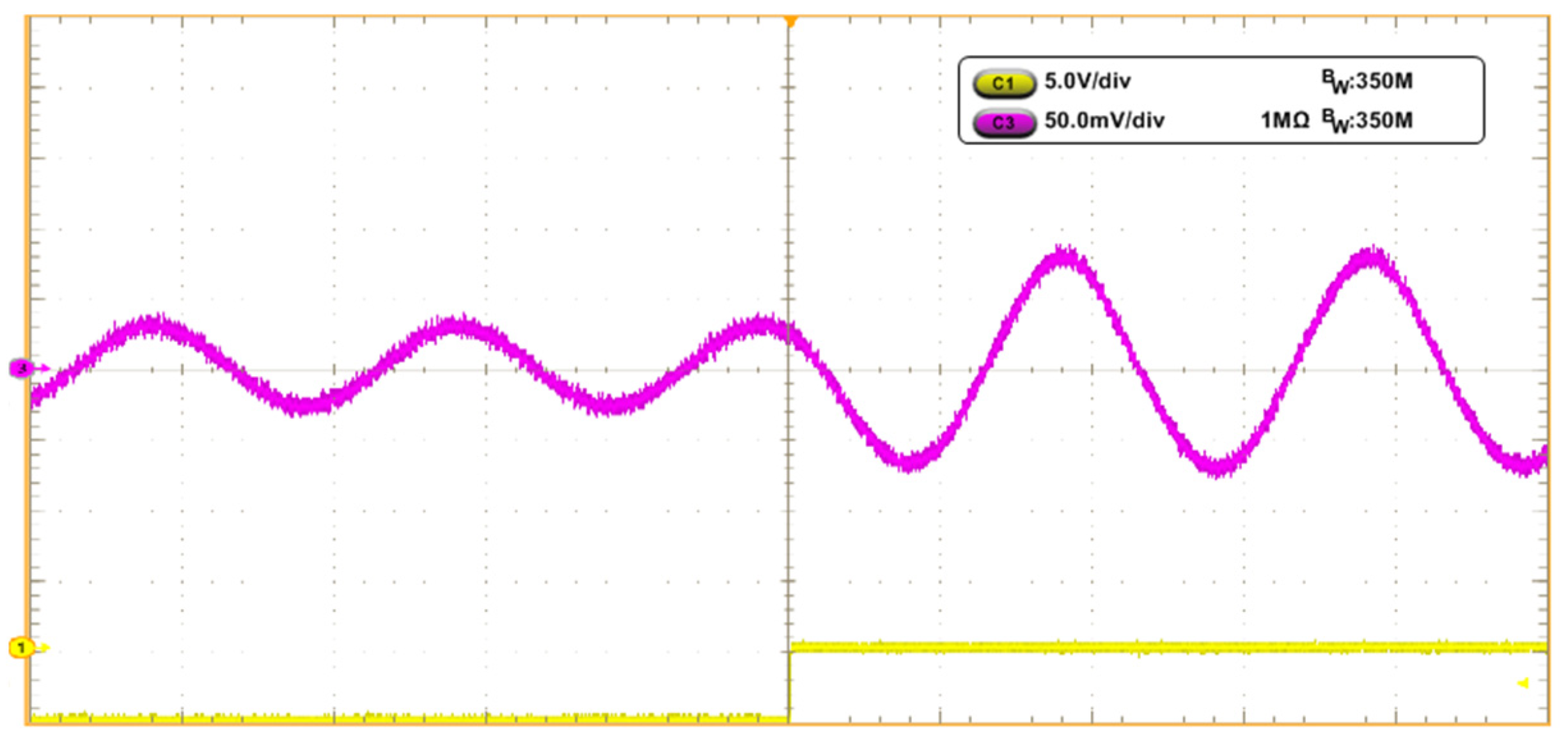
The proposed algorithm was implemented in a dual active bridge converter and tested with an energy storage and a capacitor bank. The test bench was assembled according to the diagram presented in (Figure 4). Table 2 presents the key parameters of the tested system. The capacitor bank was precharged to 60 V to create stable startup conditions. The currents were observed using a Tektronix MSO5034B oscilloscope and current probes. First, an open-loop test was performed to evaluate whether there was, previously claimed, no delay (Equation (4)) for low-frequency signals. The results are presented in (Figure 8). A sinewave drove the phase D of the converter, and a magnitude step was performed. No delay between command and input current was observed.
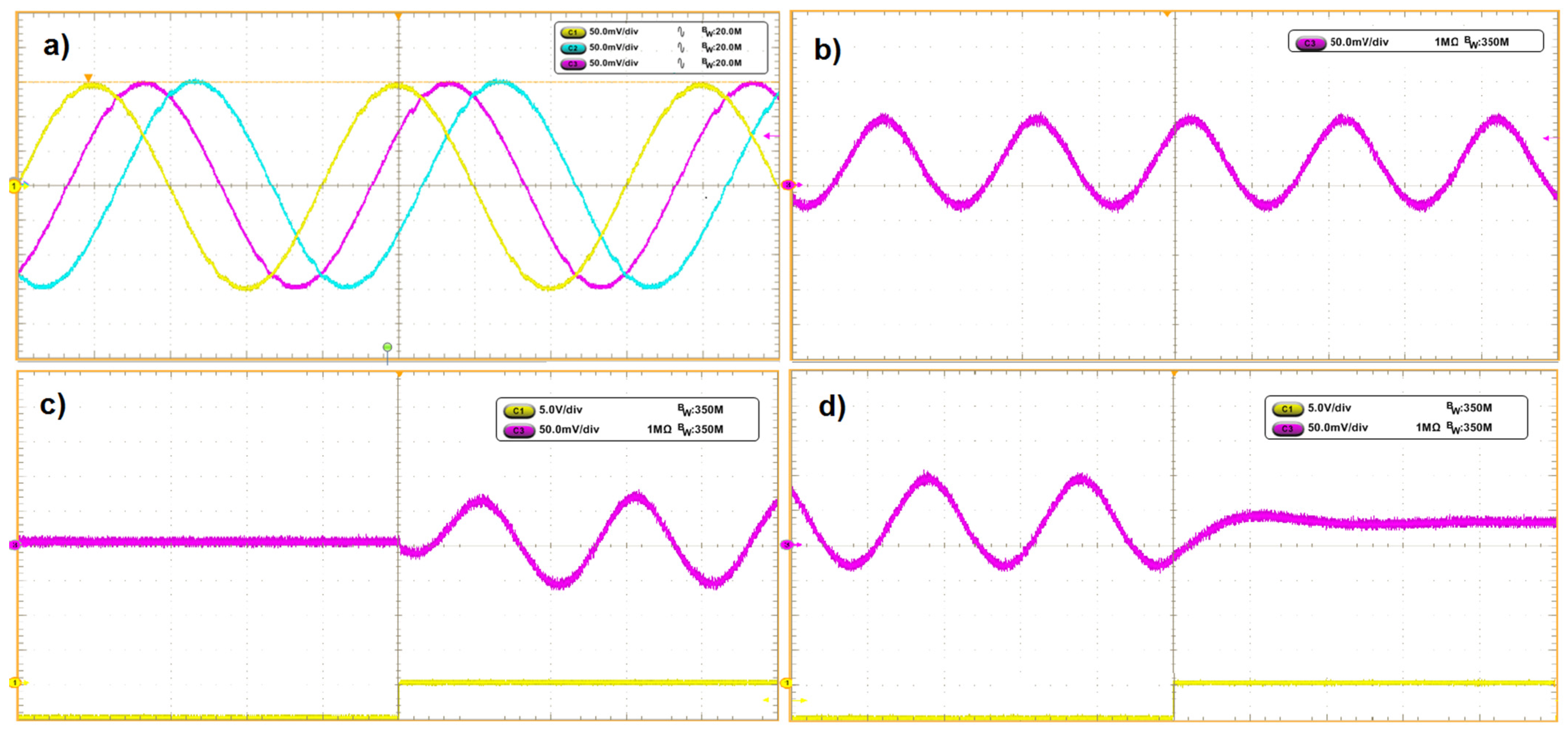
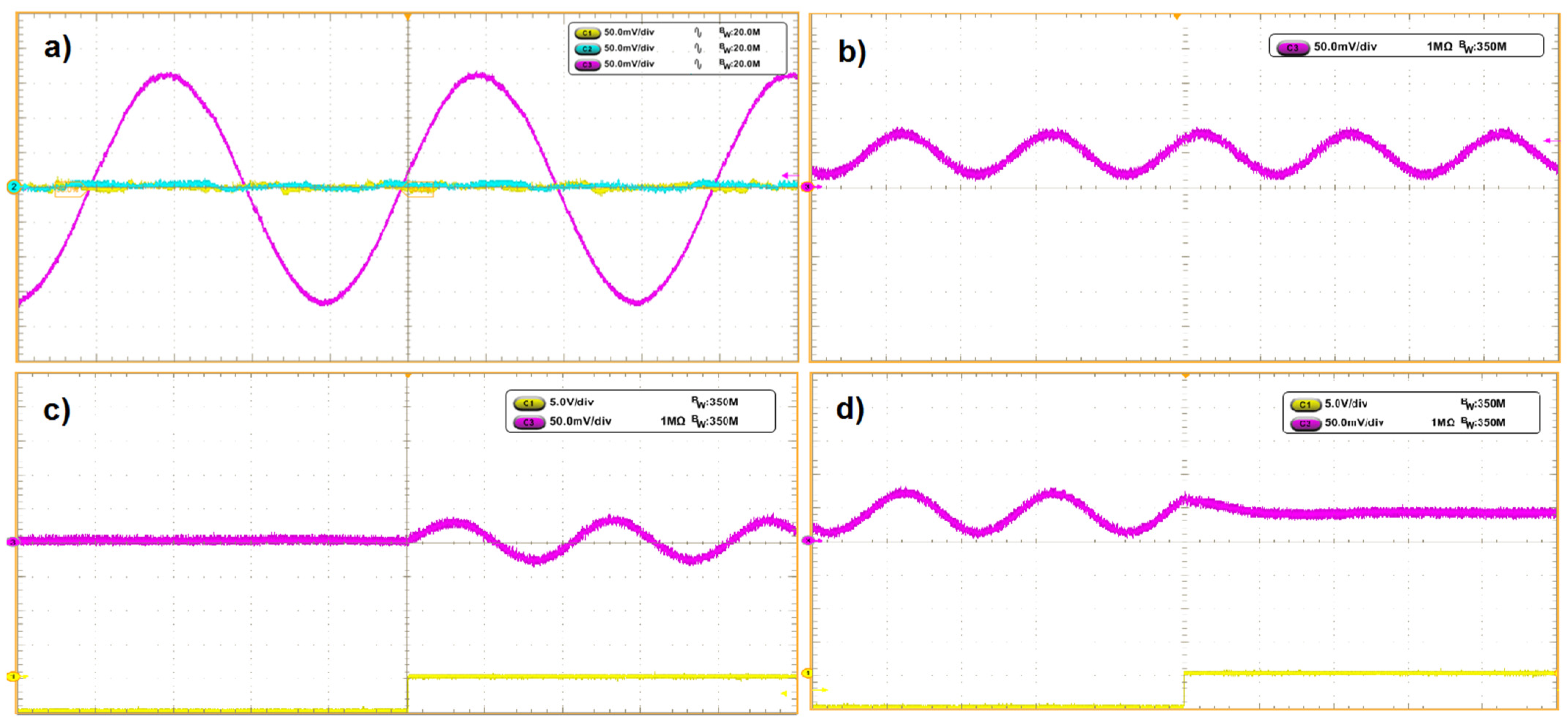
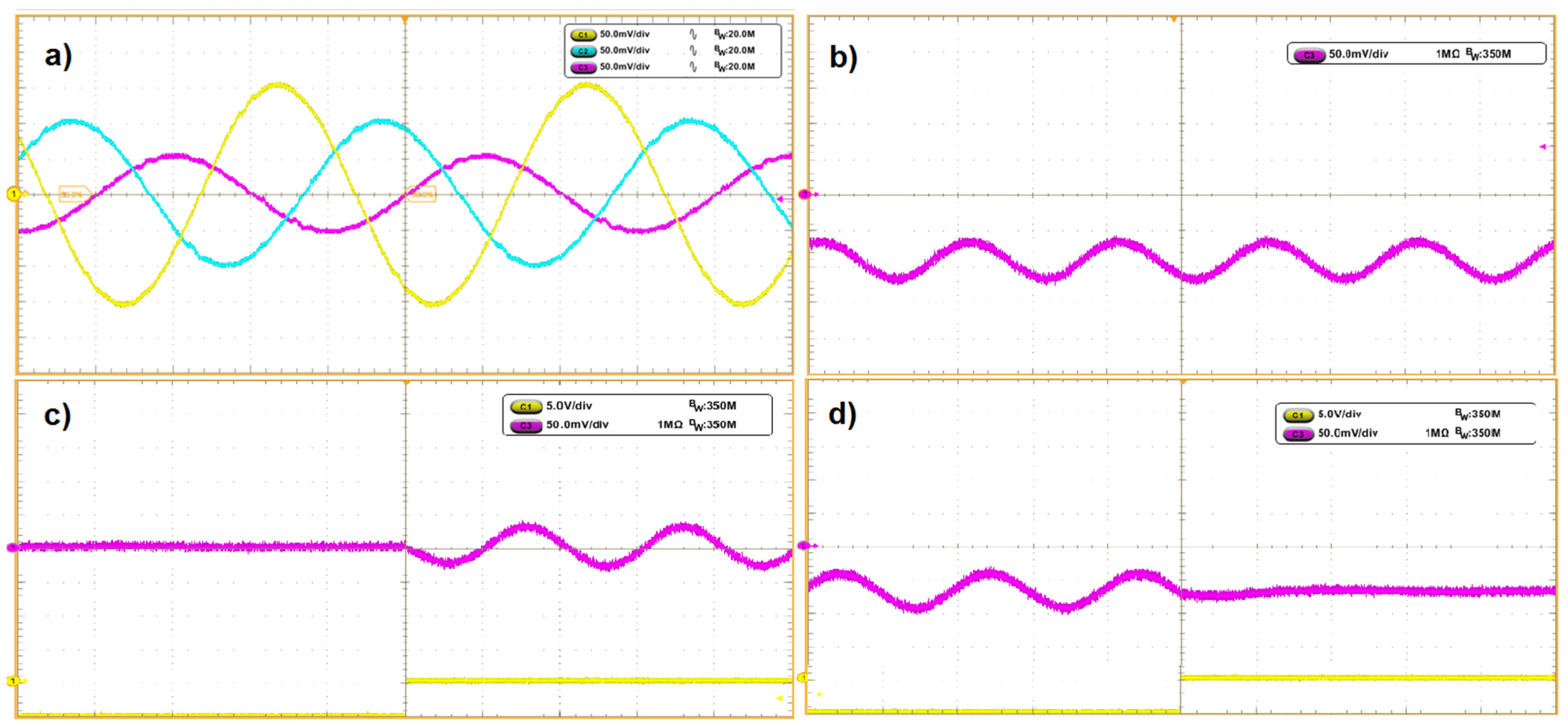
Further tests were performed with a three-phase four wire inverter connected to an energy storage and the tested converter. Three cases are presented: when Ia = Ib = −Ic = 10 A (Figure 9), Ia = 10 A, Ib = Ic = 0 (Figure 10) and Ia = 10 A, Ib = 7 A, Ic = 5 A (Figure 11).
The three presented cases were the most significant: the first case (Figure 9) created pulsation with zero crossing, and also transferred energy directly from one phase to another; the second case (Figure 10) had only single-phase delivering power, and the resulting pulsation had an offset—the energy was drawn from the DC link. The third case (Figure 11) had three different currents being drawn and delivered by the inverter, with the resulting current feeding the DC link.
The first case (Figure 9) was considered the most severe, since the energy was directly transferred from one phase of the inverter to another. The phases A and B operated in an inverter mode, while phase C operated in a rectifier mode. In this case, the DC component of the DC link current was at 3.7 A, while the AC component was at 5.2 A. In another case (Figure 10), the inverter compensated voltage in the A phase. The DC link current was at 5 A for the DC component, and 3.5 A for the AC component. In the last case (Figure 11) inverter output currents were adjusted to the level of asymmetry between the phases. This scenario has the highest probability of occurrence in the grid and has the least level of AC pulsation—2 A, where the DC component has a value of 8.5 A. Since the DC link was under the current with only 100 Hz pulsation, the DC/DC converter response was almost immediate, and only minor fluctuation is visible during the startup.
5. Conclusions
This paper presents a topology and an algorithm for compensating an AC component of a DC link current. The problem covered in the paper relates to four-wire inverters operating in high asymmetry mode in order to compensate voltage asymmetry in the utility grid. The novelty presented in the paper is the introduction of a parallel DC/DC converter with a supercapacitor along with a control algorithm, which was based on resonant regulators in order to optimize operation of the supercapacitor and compensate AC component of a DC link current.
This problem was studied in three cases: Ia = Ib = −Ic = 10 A, Ia = 10 A, Ib = Ic = 0, and Ia = 10 A, Ib = 7 A, Ic = 5 A. In all the cases, the pulsation was reduced almost to zero. This result was possible due to the dual active bridge converter response being 500 times faster than the compensated pulsation. The implemented control loop based on resonant controllers allowed for quick and accurate elimination of 100 Hz pulsation, appearing in systems feeding an unbalanced, 50 Hz utility grid. Using the high-gain resonant compensators allowed absolute compensation of the DC link pulsation. As shown in the results (Figure 9, Figure 10 and Figure 11), the entire pulsation was taken over by the DAB capacitor bank branch of the renewable system. DAB converter dynamics combined with resonant controllers create an effective system to compensate AC pulsation in DC link current. This solution is intended for systems with independent power control in each of the phases operating with electrochemical energy storages, as these are the systems in which the problem of DC link pulsation is likely to appear. Additional research should focus on compensating higher harmonics appearing in the DC link—several harmonics could be compensated using a single DAB converter. Another problem to be considered would be compensating current pulsation caused by the four-wire inverter itself. Future research focusing on the dual active bridge converter in this type of application would include the effect of deadband in the converter on the symmetry of the generated sinewave. Additionally, in this work, due to the utilization of a supercapacitor with a capacitance of 93 F, the voltage fluctuation was able to be neglected; future work should attempt to discover the minimal capacitance required for the device to operate in stable conditions.
Author Contributions
Conceptualization, D.Z. and K.F.; methodology, D.Z.; software, K.F.; validation, D.Z. and K.F.; formal analysis, D.Z.; investigation, D.Z. and K.F.; resources, D.Z.; data curation, D.Z. and K.F.; writing—original draft preparation, D.Z. and K.F.; writing—review and editing, D.Z. and K.F.; visualization, D.Z. and K.F.; supervision, D.Z.; funding acquisition, D.Z. All authors have read and agreed to the published version of the manuscript.
Funding
This research received no external funding.
Institutional Review Board Statement
Not applicable.
Informed Consent Statement
Not applicable.
Acknowledgments
This work was supported by Lublin University of Technology, Grant No FP-2/EE.
Conflicts of Interest
The authors declare no conflict of interest.
References
- Kein, H.C.; Yun, S.L.; Jianhui, W.; Philip, T.; Ezra, M.; Stella, M. Voltage Unbalance Mitigation in Low Voltage Distribution Networks with Photovoltaic Systems. J. Electron. Sci. Technol. 2012, 10, 1–6. [Google Scholar]
- Piasecki, S.; Jasiński, M.; Milicua, A. Brief view on Control of Grid-Interfacing AC-DC-AC Converter and Active Filter under Unbalanced and Distorted Voltage Conditions. Int. J. Comput. Math. Electr. Electron. Eng. 2011, 30, 351–373. [Google Scholar] [CrossRef]
- Dai, M.; Marwali, J.J.M.N.; Keyhani, A. A three-phase four-wire inverter control technique for a single distributed generation unit in island mode. IEEE Trans. Power Electron. 2008, 23, 322–331. [Google Scholar] [CrossRef]
- Vázquez-Guzmán, G.; Martínez-Rodríguez, P.R.; Sosa-Zúñiga, J.M. High Efficiency Single-Phase Transformer-less Inverter for Photovoltaic Applications. Ing. Investig. Technol. 2015, 16, 173–184. [Google Scholar]
- Cortajarena, J.A.; Barambones, O.; Alkorta, P.; De Marcos, J. Sliding mode control of grid-tied single-phase inverter in a photovoltaic MPPT application. Sol. Energy 2017, 155, 793–804. [Google Scholar] [CrossRef]
- Ji, Y.; Wang, C. Heating strategies for Li-ion batteries operated from subzero temperatures. Electrochim. Acta 2013, 107, 664–674. [Google Scholar] [CrossRef]
- Stuart, T.A.; Hande, A. HEV battery heating using AC currents. J. Power Sources 2004, 129, 368–378. [Google Scholar] [CrossRef]
- Rodriguez, P.; Pou, J.; Bergras, J.; Candela, J.I.; Burgos, R.P.; Boroyevich, D. Decoupled double synchronous reference frame PLL for power converters control. IEEE Trans. Power Electron. 2007, 22, 584–592. [Google Scholar] [CrossRef]
- Jarzyna, W. A survey of the synchronization process of synchronous generators and power electronic converters. Bull. Pol. Acad. Sci. Tech. Sci. 2019, 67, 1069–1083. [Google Scholar]
- Falcones, S.; Mao, X.; Ayyanar, R. Topology comparison for Solid State Transformer implementation. In Proceedings of the IEEE PES General Meeting 2010, Minneapolis, MN, USA, 25–29 July 2010; pp. 1–8. [Google Scholar] [CrossRef]
- She, X.; Huang, A.Q.; Burgos, R. Review of Solid-State Transformer Technologies and Their Application in Power Distribution Systems. IEEE J. Emerg. Sel. Top. Power Electron. 2013, 1, 186–198. [Google Scholar] [CrossRef]
- Krismer, F. Modeling and Optimization of Bidirectional Dual Active Bridge DC-DC Converter Topologies. Ph.D. Thesis, ETH Zurich, Zurich, Switzerland, 2010. [Google Scholar]
- Barlik, R.; Nowak, M.; Grzejszczak, P. Power transfer analysis in a single phase dual active bridge. Bull. Pol. Acad. Sci. Tech. Sci. 2013, 61, 809–828. [Google Scholar] [CrossRef] [Green Version]
- Innoue, S.; Akagi, H.A. Bidirectional DC-DC Converter for an Energy Storage System with Galvanic Isolation. IEEE Trans. Power Electron. 2007, 22, 2299–2306. [Google Scholar] [CrossRef]
- Qin, H.; Kimball, J.W. Generalized Average Modeling of Dual Active Bridge DC–DC Converter. IEEE Trans. Power Electron. 2012, 27, 4. [Google Scholar]
- Qin, H.; Kimball, J.W. Closed-Loop Control of DC–DC Dual-Active-Bridge Converters Driving Single-Phase Inverters. IEEE Trans. Power Electron. 2014, 29, 1006–1017. [Google Scholar]
- Das, D.; Mishra, S. Design Architecture for Continuous-Time Control of Dual Active Bridge Converter. IEEE J. Emerg. Sel. Top. Power Electron. 2021, 9, 3. [Google Scholar] [CrossRef]
- Krishnamurthy, K.; Ayyanar, R. Building Block Converter Module for Universal (AC-DC, DC-AC, DC-DC) Fully Modular Power Conversion Architecture. In Proceedings of the IEEE Annual Power Electronics Specialists Conference, Orlando, FL, USA, 17–21 June 2007. [Google Scholar]
- Islam, S.; Zeb, K.; Din, W.; Khan, I. Design of a Proportional Resonant Controller with Resonant Harmonic Compensator and Fault Ride Trough Strategies for a Grid-Connected Photovoltaic System. Electronics 2018, 7, 451. [Google Scholar] [CrossRef] [Green Version]
Figure 1.
Worst-case scenario of energy flow and grid voltage unbalance.

Figure 2.
Three-phase, four-wire inverter (three-level, T-type with LCL filter) and unbalanced current output during local grid balancing operation.
Figure 2.
Three-phase, four-wire inverter (three-level, T-type with LCL filter) and unbalanced current output during local grid balancing operation.

Figure 3.
Control algorithm of a single phase of a three-phase four-wire inverter.

Figure 4.
Three-phase four-wire inverter with an energy storage and pulsation compensating circuit.

Figure 5.
(a) Dual active bridge; (b) Transformer current.

Figure 6.
Proposed control algorithm for compensating DC link current.

Figure 7.
Bode plot of control algorithm for compensating DC link pulsating current.

Figure 8.
Step response of DAB converter input current (yellow signal—step time marker, purple signal—input current) (Step from 4 A into 12 A), (current: 50 mV/div, step: 5 V/div).
Figure 8.
Step response of DAB converter input current (yellow signal—step time marker, purple signal—input current) (Step from 4 A into 12 A), (current: 50 mV/div, step: 5 V/div).

Figure 9.
Experimental results (a) three-phase current on inverter output (b) DC link current without compensation (c) DAB current during compensation startup, (d) DC link current during compensation startup (currents: 50 mV/div, step: 5 V/div).
Figure 9.
Experimental results (a) three-phase current on inverter output (b) DC link current without compensation (c) DAB current during compensation startup, (d) DC link current during compensation startup (currents: 50 mV/div, step: 5 V/div).

Figure 10.
Experimental results (a) three-phase current on inverter output (b) DC link current without compensation (c) DAB current during compensation startup, (d) DC link current during compensation startup (currents: 50 mV/div, step: 5 V/div).
Figure 10.
Experimental results (a) three-phase current on inverter output (b) DC link current without compensation (c) DAB current during compensation startup, (d) DC link current during compensation startup (currents: 50 mV/div, step: 5 V/div).

Figure 11.
Experimental results (a) three-phase current on inverter output (b) DC link current without compensation (c) DAB current during compensation startup, (d) DC link current during compensation startup (currents: 50 mV/div, step: 5 V/div).
Figure 11.
Experimental results (a) three-phase current on inverter output (b) DC link current without compensation (c) DAB current during compensation startup, (d) DC link current during compensation startup (currents: 50 mV/div, step: 5 V/div).


Table 1.
Resonant compensator parameters.
| Parameter | Value |
|---|---|
| Base resonant gain G1 | 60 |
| Resonant gain for first harmonic (100 Hz) KH1 | 60 |
| Resonant gain for n-th harmonic KHn, where H—number of the harmonic | G1/H |
| Resonant span for first harmonic ωR1H | 6.28 |
| Resonant span for n-th harmonic ωRnH | 2 × π × H |
| Resonant frequency for the first harmonic ω0 | 100 Hz |
| Resonant frequency for the n-th harmonic | 100 Hz × H |
| Low pass filter cutoff frequency ωLPF | 0.1 Hz |
Table 2.
Test system key parameters.
| Parameter/Device | Value/Type |
|---|---|
| Energy storage | BMZ ESS 9.0 |
| DAB secondary capacitance Cdab_S | LS Mtron LSUM086R4C 0093F |
| DAB 1 & 2 rated power Pn | 6 kW |
| DAB 1 & 2 switching frequency fs | 50 kHz |
| DC Link Voltage | 750 V |
| Energy storage and capacitor bank voltage | 60 V |
Publisher’s Note: MDPI stays neutral with regard to jurisdictional claims in published maps and institutional affiliations. |
© 2021 by the authors. Licensee MDPI, Basel, Switzerland. This article is an open access article distributed under the terms and conditions of the Creative Commons Attribution (CC BY) license (https://creativecommons.org/licenses/by/4.0/).
Share and Cite
MDPI and ACS Style
Zieliński, D.; Fatyga, K. Dual Active Bridge as a DC Link Current Pulsation Compensator in Energy Storage Applications. Energies 2021, 14, 6141. https://doi.org/10.3390/en14196141
AMA Style
Zieliński D, Fatyga K. Dual Active Bridge as a DC Link Current Pulsation Compensator in Energy Storage Applications. Energies. 2021; 14(19):6141. https://doi.org/10.3390/en14196141
Chicago/Turabian StyleZieliński, Dariusz, and Karol Fatyga. 2021. "Dual Active Bridge as a DC Link Current Pulsation Compensator in Energy Storage Applications" Energies 14, no. 19: 6141. https://doi.org/10.3390/en14196141
Note that from the first issue of 2016, this journal uses article numbers instead of page numbers. See further details here.