
Review on Dynamics of Offshore Floating Wind Turbine Platforms


Frank H. Dotterweich College of Engineering, Texas A&M University Kingsville, Kingsville, TX 78363, USA
*
Author to whom correspondence should be addressed.
Energies 2021, 14(19), 6026; https://doi.org/10.3390/en14196026
Submission received: 28 July 2021
/
Revised: 11 September 2021
/
Accepted: 13 September 2021
/
Published: 22 September 2021
(This article belongs to the Special Issue Real-Time Monitoring and Control for Wind Turbine Systems)
Abstract
:This paper presents a literature review of the dynamics of offshore floating wind turbine platforms. When moving further offshore, there is an increase in the capacity of wind power. Generating power from renewable resources is enhanced through the extraction of wind energy from an offshore deep-water wind resource. Mounting the turbine on a platform that is not stable brings another difficulty to wind turbine modeling. There is a need to introduce platforms that are more effective to capture this energy, because of the complex dynamics and control of these platforms. This paper highlights the historical developments and progresses in the design of different types of offshore floating wind turbine platforms needed for harvesting the energy from offshore winds. The relative advantages and disadvantages of the platform types with the design challenges are discussed. The major types of floating platforms included in this study are tension leg platform (TLP) type, spar type, and semisubmersible type. This study reviews the previous work on the dynamics of the floating platforms for a single turbine and multiple turbines under various operating environmental conditions. The numerical methods to analyze the aerodynamics of the wind turbine and hydrodynamics of floating platforms are discussed in this paper. This paper also investigates the performance of analytical wake loss models of Jensen, Larsen, and Frandsen that can provide guidelines for using these wake models in future applications. There are still a lot of challenges that need to be addressed to study the accurate behavior of floating platforms operating under combined wind–wave environmental conditions. With the current technological advancements, the offshore floating multi-turbine platform can be a potential solution to harness the abundant offshore wind resource. Based on this literature review, recommendations for future work are suggested.
1. Introduction
Since 2000, wind power is playing a major role as one of the largest sources of renewable power generation globally, and is also a rapidly growing source of modern electricity supply in the United States [1]. Globally, the wind resource in deep water (depths > 60 m) is very abundant. The potential of this wind resource in the US is ranked second to China. The potential of wind resources within 50 nautical miles of the United States’ coast can generate 900 GW of electricity in deep waters. This is greater than the total electricity generating capacity installed in the US. Due to the abundance of potential at these depths, the wind turbines will need the design of a floating platform, because the wind turbines that are currently in operations are mostly fixed at the bottom and are dependent upon conventional concrete with a gravity base that is not feasible at these depths [2,3].
Much of the knowledge about offshore wind energy generation is derived from the oil and gas industry, which in the 1920s, designed and experimented with offshore structures. Nowadays, due to the existing technology of oil and gas, depths of thousands of meters can be reached. The year 1947 marked the installation of the first offshore platform in Louisiana which was 6 m deep in water. There is one significant difference between wind and oil platforms: the latter is designed with a focus on the actions of the wave and load of cargo, whereas the wind turbine platform additionally needs to focus on the speed of wind, which is not of much importance for the oil platforms due to their rigidity. Even though similar physical principles are involved in both cases, there exists a difference of primary actions, weight, and functions that evoke the need for increasing the knowledge of offshore non-oil purpose lighter structure for building confidence to create and sustain the floating platform structures [4].
The United Kingdom leads the world in offshore wind power installation with a capacity of 34% of total offshore wind installations, followed by Germany and China with 28% and 20% of total installations, respectively [6]. Offshore wind deployment is set to expand to Oceania and North America with the projects that would be built in the forthcoming years. Asia would become the prominent leader globally in offshore wind power commissioning in the next three decades, with a total capacity exceeding 100 GW by 2030 and 600 GW by 2050, as shown in Figure 1. Regardless of the effect of the COVID-19 pandemic, the global offshore wind capacity increased by 5.2 GW in 2020, bringing the total capacity to 32.5 GW [7]. If anything, the pandemic has helped to strengthen the attractiveness of the offshore wind sector with governments pursuing to “build back better” and reach “net zero”.
The next section discusses the historical development of the different types of floating platforms and summarizes their advantages and disadvantages. The third and fourth sections review the previous work on the dynamics of a single wind turbine and multi-wind-turbine floating platforms. The fifth section includes the discussion on numerical methods for the aerodynamics and hydrodynamics of the floating platforms and the performance investigation of the analytical wake loss models. The last section summarizes the conclusion with recommendations for future work.
2. Floating Wind Turbines
A balance among the two varying principles (i.e., the requirement for a stable foundation for the wind turbine’s control and operation and the nature of the substructure being innate, to respond to environmental forces) is required for the design of the floating platform for wind energy [8]. As explained in Figure 2, the absence of rigid foundations results in an additional six degrees of freedom (DOFs) for the platform of floating turbines; three translational (surge X, sway Y, and heave Z) and three rotational (roll RotX, pitch RotY, and yaw RotZ). For the platforms of onshore wind turbines and bottom-mounted offshore wind turbines, the effect of soil–structure interaction (SSI) can be modeled with six degrees of freedom; three translational (horizontal forces in X and Y and vertical force in Z) and three rotational (rocking moments in X and Y and a torsional moment in Z) respectively.
The soil–structure interactions have a positive effect on the structural vibrations of the system, as they add damping. The peak shear force and peak bending moment in the foundation are not affected by the SSI [10].
One of the challenges encountered due to the floating of wind turbines is that it is impossible to eliminate the motion that is caused due to wave and wind conditions. Thus, the turbine’s design should also consider the added DOF due to the platform’s movement. The four important concepts of the floating platform are as given in Figure 3. In each concept, a different approach is used to achieve hydrostatic stability. These concepts include a semi-submersible platform (buoyancy and ballast stabilized Dutch tri-floater), a barge platform (buoyancy stabilized), a spar buoy platform (ballast stabilized), and a Mono-hull TLP (Tension Leg Platform stabilized by a mooring line) [11,12].
To achieve the lowest overall cost of the whole platform system for its entire life, it is necessary to optimize the floaters for wind turbines because as the depth increases, the construction cost of the wind farm increases due to the floating foundation [14]. The breakup of the total cost of the system for a typical TLP type floating offshore wind turbine is shown in Figure 4, which includes the costs of maintenance, decommissioning, and operations.
Although weighing the significance of every element differently, the design of wind platforms will include the same issues governing the oil and gas platforms. To control pitch, heave motions, and support the turbine’s weight, the floating structure should provide enough buoyancy. Offset by high winds, the extra costs of the system of power distribution and the floating structure determines the economics of the wind turbines in deep water. As proved by the integrated cost models of energy, if the platform cost is managed near to 10% of the overall capital cost of the system, then the USD 0.05/kWh goal of the Department of Energy (DOE) cost is possible to attain [8,15].
The historical development of distinct types of floating platforms is discussed as follows. With the use of catenary mooring lines and the spar-buoy concept, Tong [16], created a 1.4 MW floating turbine in 1998. To assess the floater’s performance, an in-depth dynamic analysis was conducted, both for the performance of the mooring system and its design including the impact of unsteady and steady wind and wave loads. The statistics of dynamic mooring lines and motion response because of the low-frequency motion and high wave frequency were estimated. Tong observed that the main loads acting at the tower are wave loadings but were not severe, thus becoming the tower’s main design driver. In addition to this, the gyroscopic yaw motion which was caused due to the platform pitch resulted in being small and not causing any serious harm.
The research conducted by Musial et al. [17] found that TLP (Tension Leg Platform) with a vertical mooring had good stability because of the spread of multiple tension legs. A low wave loading was experienced for a tension leg platform when most of the platform is submerged. Larger forces were experienced by the vertical anchors compared to the anchors consisting of catenary mooring lines. To compare the concept of TLP with a tri-floater, a cost analysis was conducted, as per the results; TLP with a small structure would cost less when compared to the Tri-floater concept.
Ushiyama et al. [18] explained the different concepts of floating turbines to be positioned in the Japanese waters. Due to a low center of gravity, it was considered that placing the wind turbines with a vertical axis on the top of the floating structure would be suitable and will be able to get wind without the need of a yawing system from any direction. However, as per the preliminary study conducted, no clear concept was found out as the case for various floating structures. As every type consists of disadvantages and advantages, the choice of platform concept relies upon the application and site. Research which was conducted by Butterfield et al. [8] further illustrated this, where a comparison was done on the disadvantages and advantages of the 3 major floating concepts.
A scale model test was carried out by Nielsen et al. [19] in 2006, on the Hywind concept, which was introduced by the Siemens Power Generation and a Norwegian company Norsk Hydro. This was a spar-buoy-type platform. In Trondheim, the testing (80 m × 50 m) basin of the scale model was done at Ocean Basin Laboratory. To add the damping of tower motions, a control algorithm was simulated which showed the effectiveness of the controller in lowering the induced tower motions. The results of the scale model test were similar to the results of this simulation.
A detailed design of the structure of TLP was introduced by Nihei et al. [20], for a system of 5 MW turbines. Similar to the development of oil and gas, the system of TLP is interesting because of being lightweight. With the observations from analysis and model tests, the authors showed that the TLP tendons may result in capsizing the hull and might suffer the loss of tension, if not handled carefully. The combination of structure heel and rotating thrust vector can initiate structure precedence that may result in loss of tension in one or more tendons. To align the blades with the changing direction of the wind, the nacelle weathervanes might have the same precession effect. Their simulation avoids the set-down effects and solely depends on the simple Morison formulation.
Furthermore, Jagdale and Ma [21] presented another analysis that involved the use of slender-body estimation in a non-linear way. The impact of changing cross-section and pontoon length was shown in their parametric study, causing a reduction in the pitch motion in the structure of TLP. As their research focused more on the floater, not emphasizing much on the alterations in the thrust force vectors, they did not present any explanation on the impact of gyroscopic instability.
The advantages of the semi-submersible technology were highlighted by Roddier et al. [22], which includes the outfitting, construction, assembly, and commissioning that can be completed on the dock that follows the deployment and tow-out. An essential element to this is that the installation of the turbine can be finished before the tow-out; hence, the cost of installation vessels and heavy lift barges can be saved. To allow for the standard wind turbine (5 MW), the researchers have adjusted the concept of wind float. At the base of the columns, octagonal heave plates are placed which introduces inertial resistance to motion. The spar’s characteristics of hydrodynamic motion in a stormy sea state are more significant than those of semisubmersible.
For an offshore wind turbine, the addition of an oscillating water column to a semisubmersible platform was considered by Aubault et al. [23]. It has been revealed in their experiment and analysis that the rotational motions (pitch and roll) of the foundation may be increased with the take-off power and the oscillating water column. However, for improving the effectiveness, such combined devices are not considered to be right for the system.
Utsunomiya et al. [24] discussed the hybrid spar with a precast concrete segment which forms the lower area of the spar and the upper part being constructed with steel. Precast segments were used in the lower part of the platform constructed by pre-tested concrete. The tower constructed by steel was similar to the land-based wind turbine, with the additional use of conventional catenary mooring systems. The utilization of the pre-stressed concrete for the lower part is beneficial as the purpose was to lower the production cost of the platform. The quantities that were measured were the speed of the wind and the direction of the wind at the tower, the current from the power generator, and the voltage. At the base, the platform’s six degrees of freedom motion (pitch, roll, and heave acceleration and angular velocities in pitch, roll, and yaw) were also measured using a gyro sensor. The platform stabilization by damping the wind and wave-induced motions was employed using gyros [25,26].
Huijs et al. [27] presented a semi-submersible tri-floater wind turbine concept designed for optimal response in wind and waves. Stiffened steel plates are used for the design of the structure without any bracings for columns that are less prone to fatigue at stress concentrated welded joints. A similar concept was designed by Krimirad and Michailides [28] with a V-shaped braceless semisubmersible floating platform.
A moveable floating wind turbines concept was introduced in [29], to optimize the wake losses in an offshore wind farm. This conceptual design allows the wind turbines to move within a triangular area with 2 degrees of freedom. A square type semi-submersible multi-unit floating wind turbine concept was developed by Kim et al. [30,31]. This concept was extended to place multiple wave energy converters on the floating platform to make it a hybrid platform [32,33]. The pros and cons of different floating platform technologies can be summarized as given in Table 1.
The type of the platform can be selected based on the site requirements, the number of turbines, mooring system, construction, outfitting, assembly, commissioning, hydrodynamic behavior, and also the operating conditions at the sea. The next two sections discuss the literature review for the dynamics of offshore floating wind turbines.
3. Previous Work on Single Wind Turbine Floating Platforms
Sophisticated and reliable tools are required for the manufacturing and design of cost-effective and optimized floating wind turbines that can generate the required response and dynamics properly and effectively [35]. Due to the complexity in the coupling of hydrodynamics, aerodynamics, and structural dynamics, it is difficult to predict the characteristics of wind turbines. Calculating the loads is important to get exact and useful analysis outputs in the design phase of the offshore floating wind turbine. Figure 5 shows the various operating conditions of a floating wind turbine [36,37].
The operating conditions also include the aerodynamic damping (2–5%) [38], initiated by the turbine rotor, the gyroscopic loads of the blades, the viscous resistance caused by the interactions of wave and body, and the hydrodynamic loads that resulted due to the excitation of waves [39]. Due to the hydrodynamic effects, the rotors of offshore wind turbines are under platform-induced rotating motions. Non-linear aerodynamics and unsteadiness in operating turbines are induced by the coupled motion of the rotating rotor and platform pitching. This has a strong impact on the performance of the rotor, power generation, and thrust [40].
A ship-mounted inclined-axis wind turbine was tested by Dumpleton [41] in 1985, where the ship was on a swinging mooring with a single blade rotor. As compared to the ship’s main engine, the main mechanism of the turbine was placed in a protected condition in the hull. Due to there being no limitation on the size and weight of the plant, the likelihood of having better and reliable equipment increases. Various technical issues were emphasized in the test and a conceptual idea of using a ship-shaped hull with an arbitrary axis turbine was conceived.
To find out the effectiveness of semi-submersible wind turbines, a numerical and analytical design tool was introduced by Henderson and Patel [42] in 1999. The key issues highlighted were finding out the best hull form for the structure of the floating turbine and creating tools for the analysis required for the motion of waves and their interaction with the platform and also the performance of the aerodynamic system. An advantage was that the vessel’s main structure was placed below the surface of the ocean; this was a benefit over the traditional structures including hull forms that are near to the surface of the water. The characterization of the motion response to the waves was done by the pontoon structure, bracing yields and columns, and the submergence of the pontoon. However, huge submersible structures are needed to float wind farms with greater displacements and deep drafts.
In the year 2004, fully coupled time-domain simulations were carried out by Withee [43], for obtaining the system response for a wind turbine (1.5 MW) under the wave and wind loading and installed on top of the TLP floater. They included the aerodynamics loading on the wind turbine and the non-linear loading on the sub-merged floater. To support the balance of the wind turbine, a tension leg spar buoy was used; the idea of choosing this was due to the small size of the platform, and therefore, the low cost per wind turbine. At the end of the spokes, the tethers of the system were attached that radiated outward from the spar cylinder. This arrangement of the spokes and the lines under tension is ensured to be very rigid in the pitch and roll modes of motion. Additionally, the simulation results were presented which were done to find out the presence of damping which might be due to the turbine’s rotor, and they noted that the damping factor was following a distinct linear law. The quadratic damping coefficient in the surge (0.048) and sway (0.045) due to the viscous drag had comparable values. They also found the bending moments of the rotor blade at the root and the typical system responses for specific wind speeds.
An analysis of the frequency domain response was carried out by Lee K.H [44], in 2004, on both Spar Buoy and TLP forms of floating wind turbines to compare the performance of the two concepts of the floater. From the solution of the complex eigenvalue problem found from equations of motion, the natural frequencies were estimated by setting the moments and exciting forces to zero and also neglecting the effect of linear damping. Approximation of the added mass matrix is done by its zero-frequency value. It was observed that the tension leg platform was generally flexible in sway and surge yet rigid to a great degree in the roll, pitch, and yaw modes, while the spar platform was observed to be rigid in sway and surge however flexible in the roll, pitch, and yaw modes.
For analyzing the spar-type turbine integrated dynamics, Skaare et al. [45] proposed a simulation model. They proposed a model similar to the Hywind, and the numerical data were then compared with the existing scaled model test outcomes. Control schemes for the wind turbine and various other environmental conditions were also considered. The platforms were designed in such a way that the modes of motions exciting from the waves have natural periods far from the range of wave frequency values. Similarly, considering the pitch restoring force, the static tilt was small as predicted. The impact and significance of the control by blade pitch angle of the wind turbine on its dynamic response for working with winds higher than the usual wind speed were shown. This proves that, for the reason of proper analysis of dynamic response, the modeling of hydro-servo-aero dynamic coupling is needed. The modeling includes the hydrodynamic model, aerodynamic rotor model, environmental conditions, and the control system. The main issue is combining the wind and wave load models and the selection of the control strategy for the blade pitch angle.
Investigations were done by Suzuki and Sato [46], in the year 2007, to see the impact of a stabilizing fin for decreasing the pitch motion of the wind floater when the fin is placed at the bottom of the support of the spar type floater. This idea closely resembles bilge keels and roll stabilization fins attached to the ship vessels. The rotational movement caused by an uneven load from the wind on the floater can be dampened about the perpendicular axis by using the above-mentioned setup, since a fin gives extra hydrodynamic mass.
A combined hydro-aero-servo-elastic analysis was presented by Jonkman and Buhl [13] for the load analysis of the 5 MW pontoon type turbine. The main motive was to find the various forces and their dynamic reactions that would be averse to a pontoon-type platform. In the model, other things that were included are sea currents, a non-linear viscous draft from the wave kinematics, platform motion, linear hydrostatic restoring, the additional damping and mass contributions from the linear radiation of waves, which included the excitation of incident waves from linear diffraction in irregular and regular sea and the impact of free surface memory. Similarly, as aerodynamic loads rely upon the state of the airfoils of the rotor blades, the hydrodynamic loads rely upon the geometry of the support platform. It was emphasized that when the response of the turbine and pitch motion of the pontoon are combined, it created greater reactions in the wind turbine blades and tower. When the wave conditions were critical the barge was sensitive for added pitching of the platform. Some alterations were proposed to minimize the boat movements.
Matsukuma and Utsunomiya [47] performed research in 2008, in which they analyzed the movement of the spar-type floater, with rotor rotation in the presence of steady wind. Using the blade momentum concept, the evaluation of the blade forces due to wind was done. The outcome of this was the production of yaw, sway, and roll motions because of the gyro-moment effect. This research was continued and the motion of the turbine was further analyzed with the use of normal and abnormal waves along with a parallel load that gave rise to the smooth flow of the wind [48]. The turbine was a 2 MW, with a diameter of 80 m and a height of 55 m. At the National Marine Research Institute, a few experiments had taken place with the use of the scaled model as well as on the stepped type floating cylinder, which showed a smaller heave and pitch movement when moored at an upper place in comparison to the uniform cylinder counterpart [49]. Another sea experiment was performed by Utsunomiya and the team, using another reduced model of a composite spar turbine [50]. The results were obtained for the six-degree motion of the tower base. The outcome thus confirmed the numerical methods as well as the computer codes used in the spar-type floating turbine analysis in the presence of various forces of wave and wind.
Furthermore, an analysis was performed by Sclavounos [51], which demonstrated a review of the turbine and the anchorage system along with all of its parameters. Different parameters including the nacelle acceleration, tension, and displacement were demonstrated that were favorable to the 5 MW wind turbine. The selection of all concepts was done carefully for the safe towing of the floater to the installation site and attaching it with the anchorage system. A large space was allocated for the concrete ballasted cylinder. The geometry of the platform was characterized by the barge draft and radius. Eight similar tethers were included in every mooring system which was divided into two groups and spaced 90 degrees apart. Four mooring line groups were included in the structure instead of having three for the system become stable in a case when one section fails to perform. Coupled dynamics of the floater along with the mooring cables were done using the existing simulation tools that are used by the offshore wind industries. It was observed that the feasible designs are shallow drafted barge ballasted or narrow deep drafted spar. The catenary and tension leg were both included in the mooring system.
Different cases were demonstrated by Suzuki et al. [52], regarding progressive drifting of the turbines in the wind farm, which was closely spaced, thus lowering the costs of installation. Collisions of turbines would result if the floating turbine drifts accidentally. Cases like these were discussed and the risks were identified about the arrangements of turbines to contribute to the safety in this matter.
Furthermore, a life cycle assessment was performed by Weinzettel [53] for the offshore floating type turbine using the concept of Sway TLP. This assessment emphasized the effects of the environment by putting forward the significance of recycling after decommissioning the wind turbine to minimize the detrimental effects on the environment. The outcomes of this assessment were compared with the processes of the Ecoinvent database for the production of electricity by the natural gas power plant and wind power plant. Secondary materials had not been included in this; however, they included the recycling of metals for avoiding the production of materials. Their structural design had the submerged tower under the sea where the upper portion of the submerged part was stuffed with air to aid the floating of the turbine and olivine ballast was filled at the bottom part which aided in balancing the wind turbine. The wind turbine was attached to the mooring part developed from stones at the bottom of the sea with the help of the torsion leg.
A study, regarding the wind float foundation, was conducted by Cermelli et al. [54,55,56,57] in three parts, the structure of this foundation is shown in Figure 6. The wind float consists of a three-legged foundation for huge offshore turbines. This design aids the accommodation of a 5 MW or greater turbine enabling fewer changes to the nacelle, turbine, and tower.
The first part [55] of the research emphasized the structural design of the turbine foundations in which the writers highlighted the importance of wind turbines design in collaboration with oil/gas platform technology. A hydrodynamic analysis was done on the floating foundation hull, which was presented in the second part [56] of their research. They demonstrated the following: a numerical model for platform hydrodynamics and a mooring system, a simulation of the aerodynamics of the floating turbine using a scaled model in the wave tank test basin, and coupling of aerodynamics with hydrodynamics using Fatigue Structures Aerodynamics Turbulence (FAST) software.
The column-stabilized floating structure was analyzed in the third part [57] of the paper. This part emphasized the methods of determining the structural strengths and fatigues. They put forth the relation of underwater structural loading and wave loading and showed that the former was dependent on the latter. They further suggested that because of the significance of aerodynamic loading, an analysis should be carried out on the truss bracing members of the turbine tower and column interface.
Frequency domain analysis was carried out on a floating turbine by Matha [58], where it was shown that the force of aerodynamic thrust balanced the force of the mooring line, in the case of a TLP. To obtain equilibrium, a negative moment was generated by the deflection of tension to counter the positive moment from the force of the wind. Many loads of stochastic aerodynamic appear, additionally with the uniform and periodic loads, on the operating wind turbine. The majority of this is generated from the disturbance that was considered to be an arbitrary change in the speed of wind within a mean value. This turbulence was of various intensities and results in varying loads on blades. The outcome of this could be the wrong predictions of the natural frequencies. Therefore, this lays down the significance of the calculations of floating turbines which should be carefully done in the time domain.
An analysis of the structural dynamics response in critical operating conditions was done by Moan and Karimirad [59] on a spar-type floating wind turbine. They put forth the ultimate design limit check responses in their technical research. They further discussed the impacts of severe conditions on the coupled motion of wind and waves and provided numerical calculations to verify their statements. The hydro-aero-servo-elastic simulation in the time domain gave these severe responses to the structure. A Gaussian process and dominant platform pitch responses from induced wind were observed from their results.
Another analysis of coupled floater rotor tether dynamics was done on a TLP platform by Bae et al. [60], which included the mooring dynamics, platform motions, and blade rotor dynamics numerically simulated in the time domain. In addition to the dynamic coupling of floater and mooring, the coupling of floater and rotating blades’ dynamics were examined and analyzed after which they were compared with the uncoupled dynamics. The results of the comparison showed that the high frequencies give rise to much better rotor dynamics in the coupled simulations with implications on fatigue life. Thus, their study concluded that in steady currents, irregular waves, and dynamic winds, the numerical methodology is applicable in the design of modern floating turbines.
The uniform boundary layer impact on the wind turbine was observed and examined with the use of an in-house flow solver by Sorenson et al. [61]. This was done for simulating the transient NREL 5 MW baseline offshore wind turbine with a discussion on both steady and unsteady simulations. A dual time-stepping method was suggested for the unsteady ones in which solutions to equations were supplied using under relaxation iteratively. To enhance the solutions, the equations of momentum were used initially, which, however, did not fulfill the equation of continuity. Thus, the equation of continuity was made as a basis for correcting the field following the equation which was also known as the pressure correction equation. These two steps were equal to one sub-iteration, which was repeated continuously for each time step to obtain a converging solution. After this was attained, one would move on to the next time step after all the variables are updated. Their study reflects the upstream velocities as the function of individual blade load hysteresis effect in the wake velocities.
A fully coupled dynamic analysis was done to analyze a spar-type floating wind turbine to calculate the hydrodynamic parameters and performance of the mooring system under various design load cases [62]. A coupled fluid-structure simulation of a complex floating wind turbine operating under turbulent winds and large-scale ocean waves that consider the influence of aero-hydrodynamic coupling was done based on a two-fluid approach to validate the computational framework for the floating structures [63,64,65]. The aero-hydro-servo-elastic time-domain analysis was done using the Simo-Riflex-Aerodyn tool to evaluate the dynamic response of a semi-submersible offshore floating wind turbine under selected environmental operating conditions [28,66].
The numerical computations of a 10 MW offshore floating wind turbine were presented by Leble and Barakos [67]. A helicopter multi-block flow solver that solves Navier–Stokes equations was used for computing the rotor aerodynamic loads and smoothed particle hydrodynamics was used for calculating the hydrodynamic loads. A full configuration floating offshore wind turbine simulation with a rotating blade due to six degree of freedom platform was carried out in [68], to investigate blade-tip vortices, tower-blade interference, shedding vortices, and turbulent wakes in the fluid domain. A passive motion stabilizer consisting of heave plates was developed to created damping forces needed to stabilize the floating offshore wind turbine operating in relatively shallow waters [69].
In [70], the authors predicted the dynamic response of a floating wind turbine using advanced hydrodynamic models operating in combined current and wave conditions. The effects of KC (Keulegan–Carpenter) and Reynolds numbers were considered for the first time to evaluate the drag and added mass coefficients using the hydrodynamic model for both the laboratory and full-scale platforms. They found that the predicted dynamic responses are improved by the directional spreading function of the sea wave spectrum using the proposed advanced hydrodynamic models.
The dynamic behavior of an offshore floating wind turbine for operating in the Mediterranean Sea was discussed by Cottura et al. [71]. A comparison between spar-buoy and Saipem’s hexafloat [72] was carried out to optimize the Levelized cost of energy (LCOE) of the floating wind turbine platform.
An integrated aero-hydro-servo-elastic analysis was performed by Lin et al. [73], to study the impacts of water depth on the dynamics of floating wind turbines. They showed that the mooring line top tension and platform heave motion are more sensitive to water depth. The tower base bending force is also influenced as the depth of water is increased.
Based on the technological challenges, a qualitative assessment of the advantages and disadvantages of the primary floating platforms can be summarized as given in Table 2, with 1 being a relative advantage, –1 being a relative disadvantage, and 0 being neutral. This assessment is subjective and depends on the design details and installation site.
In a TLP foundation, a mooring system is used to attach the structure to the seabed with a set of pre-tensed legs. The position and predetermined location of the foundation are recovered by adjusting the tension in the legs. The spar foundation, on the other hand, is stabilized using a large cylindrical buoy. The semi-submersible foundation design was formed by combining the designs of TLP and spar type floating platforms. The semi-submersible platform provides adequate space at the base for carrying out the operation and maintenance work [74]. The TLP platform can be lowered into the water to enable the maintenance of the wind turbine by setting it within a reasonable distance of the water [75]. The LCOE for the semi-submersible platform, spar platform, and TLP platform is 88.69–105.59 USD/MWh, 95.36–107.39 USD/MWh, and 113.34–135.11 USD/MWh, respectively [76]. The semi-submersible and spar platforms have a relative advantage over the TLP platform in economic terms. This economic analysis was based on the life-cycle cost of a floating offshore wind farm that includes the costs of concept, design, construction, installation, operation, and decommissioning [77]. The next section discusses the previous research into the dynamics of offshore floating multi-wind-turbine platforms.
4. Previous Work on Multi-Wind-Turbine Floating Platforms
In 2003, various options for platform design were considered by Henderson et al. [78,79], which comprises the multiple or single turbines per floating platform, and multiple or single rotor turbines. It was initially concluded, with the help of qualitative analysis, that the best economic and technical solution was a single turbine per floater including a spread mooring. In 2004, a confirmation was made by Musial et al. [17] on this discussion. The advantages and disadvantages of both concepts were laid out. The advantages of multi-wind-turbine platforms over single wind turbine platforms include wave stability, common anchors, fewer transmission costs, and the possibility of mass optimization. The disadvantage is that the yaw control for the multi-turbine platform is complex and the support structure is relatively expensive. However, the analysis done was not complete and many issues were to be considered, including:
- ➢
- The requirement for the evaluation of barge platforms
- ➢
- Heave and roll were explained by simple equations of motion
- ➢
- The analysis did not explain the impact of waves and mooring lines
In 2006, a model based on the Fourier spectrum was applied by Zambrano et al. [80] to a 6 DOF moored type floating platform with 3 turbines installed on it. A fourth-order Newtonian Runge–Kutta approach was used to find the resulting sway, surge, and heave motions. The wave, wind, and anchorage cable tension forces were determined by varying the time. To create the wave forces on the platform, the Wave Analysis Massachusetts Institute of Technology (WAMIT) program was used. Additionally, to predict the wind turbine loads, a constant force coefficient was used.
The semi-submersible floating platform’s dynamic response was studied by Ishihara et al. [81] and Shimada et al. [82], as shown in Figure 7. The characteristics of the waves causing these motions were presented in their research. In addition, 1:150 reduced model examinations were conducted in a water container with external wave excitations. In the equation of motion and the computations, the impact of nonlinear damping because of inertia forces and fluid dynamic viscous loads (using the formula of Morison) were considered. Here, Green’s function model was used to obtain linear hydrodynamic forces. As an outcome, improvements were observed in the characteristics involved in the resonant frequency region. Additionally, the investigation was also done on the long-term fatigue limit and the stability of the structure in conditions of severe waves.
The development of the design of mobile, as well as a large structure with many wind turbines for offshore sailing type wind farms, was explained by Manabe et al. [83]. Through this study, an analysis was done on the concept of a floating wind farm adding authenticity to the realization of the concept. Considering the coupled hydro-elastic analysis, the sailing wind farm’s design was presented in this paper. In any case, the outline technique was not the same as that utilized in common structures of marine. To approximate the interactive forces between fluid and structure appropriately, a hydro-elastic analysis was important. Accurate analysis of fatigue strength was important because the offshore wind farm used the light structure rather than the common marine structure. The hydro-elastic analysis forms the basis for the design of the structures for these large offshore wind turbines, which was evident from the efforts of Japanese researchers in tapping on large mobile offshore structures to realize the importance of floating wind farms.
Resistance and towing tank tests were carried out by Kourogi [84,85] and the team with the use of a scaled model of sailing type floating wind turbine structure to enhance the simulation of navigation and also examine the interactions between the struts and semi-submersible hull. To reduce the drag of the wind force, a lift force was introduced with the aid of vertical struts on the lower hulls. To increase the energy profitable ratio (ratio between output and input energies), it was essential to create the best route to generate the maximum energy. Hence, taking into consideration the stormy weather as well as the wind power extent, they planned to build a most favorable route. The rate of wind power was set to a maximum of 40%, i.e., greater than the capacity factor. Apart from this, the wave height was set to a maximum of 6 m, above which the structure was bound to evacuate. Examinations and tests were also carried out for analyzing the performance of seakeeping. There were many dissimilarities between this design concept and that of the conventional offshore designs.
In 2011, Lefranc and Torud [86] performed feasibility, design, and cost analysis for a semi-submersible floating platform with three turbines on it. To increase the distance between the tower and rotor blades, the towers were inclined. A scaled model of 1:150 was used in experiments to investigate the wake interactions between the turbines. Wind tunnel tests were done with a turbulence intensity of 9% to replicate the offshore wind conditions and a wave basin was used to test the interaction of the platform with regular and irregular waves. It was shown that the wake interaction between upwind and downwind turbines was the most challenging issue and proved that the power loss due to the wake effect at low velocities was significant, while at high velocities it was almost unchanged. The economic analysis proved that the multi-wind-turbine concept was comparable to the current single platforms in terms of the cost of energy production.
Hu et al. [87] used a numerical model, experiment, and Computational Fluid Dynamics (CFD) simulation for the hydrodynamic analysis of a semi-submersible floating multi-wind-turbine platform. The experiment without consideration of wind on a 1:50 scaled model was carried out to check the accuracy of the two numerical models in predicting the wave-–body interaction between the waves and platform. The potential flow method was used in the numerical model to analyze the linear wave–body interactions. The CFD model was used to calculate the pressure distributions on the platform due to waves.
A fully coupled analysis was developed by Bae and team [88] that involved various turbines on a separate floating platform including mooring lines, by expanding and combining different tools of computer-aided engineering. A global combine matrix that includes all the degrees of freedom and coupling forces that are relevant solved the equation of motion for the system with various turbines on a single floating platform. As an outcome, the full coupling between the blades, towers, floater, drive-trains, and mooring framework, the dynamics of the MUFOWT (multiple units floating offshore wind turbine) was obtained in a single run. However, the wake effects of the wind turbines were not considered in this study.
Kim et al. [89] designed a control algorithm for a large semi-submersible platform with four turbines installed at each corner of the platform. ANSYS AQWA was used to obtain the hydrodynamic forces data and was implemented in GL-DNV Bladed. The gain scheduled pitch control and basic torque control with tower damper were used to reduce the tower in-plane and out-of-plane bending moments. However, the generated power standard deviation was significantly increased as a trade-off.
A square semi-submersible type MUFOWT has been recently studied and designed by South Korea which includes the installation of 3 MW wind turbines at the four corners [31,90]. In addition to placing six energy converters at each side, the twenty-four-point power absorber type linear generator-based wave energy converters (WEC) were set up. In comparison to the conventional floating platform, the submerged platform has a unique size that showed distinct dynamic characteristics in the overall performance. A series of model tests were performed by the research institute in Korea on the MUFOWT with a Froude scale of 1:50 [91]. The model tests excluded the dynamic motions of wave energy converters which were fixed to the platform.
A numerical investigation on a hybrid wind–wave floating offshore platform was done by Lee et al. [32] to analyze the multi-body hydrodynamic interactions in a frequency domain. The platform is semi-submersible with four 3 MW turbines at four corners and 24 wave energy converters on the sides. Jang et al. [33] evaluated the effect of heave plates on the behavior of a multi-unit offshore floating wind turbine using a time-domain coupled dynamic analysis. Scaled model experiments were conducted to compare the numerical simulation. They showed that the heave plates with a minimal increase of mass can reduce the pitch and heave motions and also shift their natural frequencies.
In [92], the hydrostatic stability analysis was performed on an OFMWTP (offshore floating multi-wind-turbine platform) configuration that was modeled based on the wake effect analysis. The platform configuration hosts five 8 MW wind turbines which were proposed for installing on the gulf coast of the United States [93]. They also carried out an aero-hydrodynamic analysis to study the dynamic behavior of the OFMWTP operating in coupled wind–wave conditions. They also showed that the wake effect analysis carried out in the initial stages of design greatly reduced the power deficit at the downstream wind turbines [94,95].
With the advent of high computing facilities, extensive numerical simulation of the multi-wind-turbine floating platforms is possible which can enable the development of better support structures for the platforms. The dynamics of the multi-wind-turbine floating platform is an extension of the single platform dynamics with additional degrees of freedom arising due to additional wind turbines. The advantages and disadvantages of single and multi-wind-turbine floating platforms are summarized in Table 3.
5. Numerical Methods
The numerical methods to analyze the aerodynamics of the wind turbine and hydrodynamics of floating platforms are discussed as follows.
5.1. Aerodynamics
The most commonly used aerodynamic analysis techniques for wind turbines are the classical blade element momentum (BEM) theory and the computational fluid dynamics (CFD) method.
5.1.1. BEM Model
The Blade Element Momentum (BEM) is one of the most commonly used aerodynamic analysis techniques for the wind turbine [96,97,98,99]. According to the BEM theory, the flow on the blade segment consists of the components as shown in Figure 8.
The flow angle of attack () is computed as follows
where is the angle relative to the wind, is the pitch angle, is the upstream velocity, is the axial induction factor, is the angular induction, is the rotor velocity, is the angular velocity of the rotor wake and is the angular velocity of the rotor. The normal () and tangential () force coefficients in terms of the lift () and drag () coefficients can be calculated as [100,101].
Based on Prandtl’s tip loss corrections, the new expressions for axial and angular induction factors are given as [102]
where is the local solidity function of the chord at each section of the blade, . is the number of blades, is the radius of the rotor, and is the Prandtl’s correction factor that takes into account a finite number of blades and the losses due to the air circulation at the blade tip given by
This tip loss correction factor characterizes the reduction in the forces at a radius r along the blade that is due to the tip loss at the end of the blade. This is the BEM model used for calculating the local loads on the blade element which is then integrated to find the total load on the rotor.
5.1.2. CFD Method
The equations for the inviscid, incompressible, and irrotational fluid is given by Bernoulli are as follows
where is the velocity potential, represents the flow field velocity, is the pressure, is the density, and is the gravity.
In the early seventies, the computational fluid dynamics (CFD) methods were applied to study the rotor configurations for the first time and became prominent for studying the wind turbine in recent times [40,64,68,106,107,108,109,110,111]. The flow is governed by the continuity and Navier–Stokes equations for a transient, incompressible, and viscous fluid which are as follows
where is the kinematic viscosity. An additional term is added to the Navier–Stokes equations in the Reynolds-averaging process resulting in the Reynolds-averaged Navier–Stokes (RANS) equations.
where is the additional term called the Reynolds stress tensor appears due to the non-linearity of the convective term and can be related to the mean velocity gradients through a turbulent eddy viscosity . Hence, the RANS equations are expressed as
The shear stress transport (SST) turbulence model developed by Menter is a robust two-equation, eddy viscosity turbulence model used to resolve turbulent behavior in many aerodynamic applications [40,65,68,109,110,111]. The SST turbulence model [112] can be expressed as follows
where is the effective diffusivity of the turbulent kinetic energy , is the effective diffusivity of the specific dissipation rate . and are the turbulence dissipation terms and and are the turbulence production terms. is the cross-diffusion term originated by combining the standard and models. Another important method for modeling the turbulence in wind turbine wakes is the large eddy simulation (LES) [113,114,115] that has an advantage over RANS but is computationally very expensive.
5.1.3. Wake Loss Models
The wake effect between the wind turbines is an undesired phenomenon that reduces energy production and increases mechanical loading on the downstream turbines [92,116,117,118,119]. Wake modeling is important in reducing the negative effects of the wake. There are many numbers of wake models that are developed to understand the dynamics of the wake. Jensen’s wake model, Larsen’s wake model, and Frandsen’s wake models are the analytical wake models derived based on the conservation of mass and empirical relations of wake decay [117].
- Jensen Wake Model
The Jensen model [120] is the most commonly used linear wake model to find the wake effects of the turbines. The wind speed in the wake is calculated by
where and are the mean wind speeds at the downstream and upstream of the wind turbine respectively, is the thrust force coefficient of the upstream wind turbine, is the rotor diameter, is the downstream axial distance between the wind turbines, is the wake decay constant with values of 0.075 for onshore and 0.05 for offshore conditions. The wake diameter is given by
The linear wake expansion calculated using the Jensen wake model as a function of downstream distance is shown in Figure 9. This figure shows the wake expansion at a horizontal plane through the hub of a LEANWIND 8 MW reference wind turbine with a rotor diameter of 164 m.
- Larsen Wake Model
The Larsen model [121,122,123] is a wake loss model based on the Prandtl turbulent boundary layer equations and is given as follows
where is the mean wind speed of the wake as a function of axial distance and radial distance , is the area of the rotor disk. The estimation of non-dimensional parameters and is given by
where is the effective rotor diameter given by
and is the wake diameter at a distance of 9.5 rotor diameters downstream of the turbine given by
where is the hub height of the upstream wind turbine and is given by
where is the total turbulence intensity [119] given by
where is the atmospheric turbulence intensity at hub height, assumed to be always greater than 5%, and is the wake added turbulence (for spacings larger than 2D) given by
The wake boundary developed behind the wind turbine using the Larsen wake model is as given in Figure 10. The wake expansion is non-linear and also there is an increase in the width of the wake because of the turbulence intensity .
- Frandsen Wake Model
Frandsen model [124,125,126] is developed by applying the equation of momentum to a control volume and is expressed as follows
where is the wake area and is the diameter of the wake given by
where is the wake expansion parameter given by
The wake expansion calculated using the Frandsen wake model as a function of downstream distance is as depicted in Figure 11. The wake width is increased in comparison to the Jensen model because of the additional wake expansion parameter
- Comparative study
The wind turbine used for evaluating the performance of the wake loss models is based on an 8 MW reference wind turbine [127], designed for offshore wind farms. The diameter of the rotor is 164 m and rated wind speed of 12.5 m/s which is considered as for this analysis. The propagation of the wake is estimated using the streamwise velocity downstream of the wind turbine. The normalized average velocity profiles downstream of the wind turbine using the Jensen, Larsen, and Frandsen wake models are calculated as shown in Figure 12, Figure 13 and Figure 14, respectively.
In comparison with Jensen and Frandsen’s wake models, the velocity ratio for the Larsen wake model is low in the near wake region (<2D) because of the atmospheric and wake added turbulence factor which was not considered for the other cases. After a downstream distance of 4 times the rotor diameter, the velocity ratio in all 3 cases becomes approximately equal. To predict the wake behavior accurately by including the turbulence effects, the Larsen wake model can be used. The Jensen wake model is a simple model used in cases with minimal computational effort. It is important to study the wake effects between the turbines considering the turbulence intensity for the design of multi-wind-turbine platforms and also the layout optimizations for the wind farms.
5.2. Hydrodynamics
The choice of the hydrodynamic model to analyze the hydrodynamics of the floating object depends on the characteristic size of the structure, wave height, and wavelength of the incident waves. The wave theory and potential flow theory are used for modeling the wave loadings and first and second-order hydrodynamics of the floating structure, respectively [128,129,130,131,132]. Hydrodynamic loading is estimated in terms of integrated pressure over the wetted surface of the structure that includes total forces from added mass, buoyancy, non-linear drag from viscosity, linear damping from wave radiation, and forces due to both scattered and undisturbed incident waves [133,134,135]. The potential flow theory for the hydrodynamics of the floating wind turbine is given as follows [87, 132,136].
Potential Flow Theory
In this theory, fluid is assumed to be incompressible, inviscid, and irrotational. Based on the linear wave theory, the total velocity potential which is a sum of incident (), diffraction (), and radiation potentials () can be expressed as
where , refers to the motion displacement, and corresponds to the sway, surge, heave, pitch, roll, and yaw respectively. The incident wave potential is given by the equation as
where is the wave frequency, is the amplitude of the wave, is the wave propagating direction, is the wavenumber, and is the gravitational acceleration. The total radiation force with contributions from the added mass coefficient and the radiation damping coefficient can be written as
The added mass adds to the system inertia and the radiation damping is proportional to the velocity. The wave excitation force in terms of incident and diffraction potentials is given by
where is the density of seawater, is the wetted surface area, is the surface normal vector. By combining the added mass coefficient, radiation damping coefficient, and the wave excitation force, the motion displacements can be evaluated using the 6 coupled equations as follows
where is the hydrostatic restoring matrix that also includes external stiffness from the mooring system and is the generalized mass of the offshore floating body.
5.3. Environmental Conditions
The wind and wave modeling for the coupled aero-hydrodynamic analysis of the offshore floating wind turbines can be discussed as follows.
5.3.1. Wave Spectra
Depending on the environmental conditions at the site, several wave spectra are used for the design of offshore floating structures. The joint North Sea wave project (JONSWAP) spectrum [136,137,138] is the most commonly used wave spectrum expressed as
where is the significant wave height, is a normalizing factor, peak-spectral frequency, is the peak period, and σ is a spectral width parameter with σ = 0.07 for and σ = 0.09 for .
5.3.2. Wind Speed Distribution
The accurate characterization of the offshore winds is essential for harnessing the enormous energy source. The hourly mean wind speed data are generated using the probability distribution functions. The Weibull probability distribution function is the most common method used for predicting the wind speed [96,139,140]. It is given as
where is the wind speed, and are scale and shape parameters, respectively.
5.3.3. Seismic Loads
The seismic activity can affect the floating wind platforms through seismic shaking, fault displacement, subsurface liquefication, tsunami effects, etc. For a floating foundation, the seismic activity mainly affects the anchorage system. The mooring cables transmit the seismic motion to the floating support structure. However, this motion is suppressed to a great extent due to the damping effect of water and the low mass of the mooring cables [143].
5.4. Moorings
Moorings are used as the station-keeping system for the floating platforms. A mooring system consists of cables that attach the fair lead connections of the floating platform to the seabed through the anchors. The mooring system is used to increase rotational stability by preventing the floating platform from drifting under the action of wind, waves, and currents [71]. The tension in the mooring lines creates the restraining forces at the fairleads. Hence, as the tension in the cables changes due to the movement of the platform, the restraining forces at the fairleads also change [37].
The total load acting on the floating platform from the mooring system (), if assumed as linear can be given as
where is the th component of the mooring load acting on the floating platform in its original position, is the component of the restoring matrix from the mooring system, is the displacement of the floating support platform.
5.5. Dynamic Analysis Model
The dynamics of the global system can be formulated using a six DOF rigid platform assumption. The general formulation of the differential equation of motion based on Newton’s II law for the coupled platform and wind turbine can be given as [70,80]
where is a generalized inertia matrix containing mass and moment of inertia components, is an added inertia matrix, is the radiation damping matrix due to outgoing waves generated by the moving floater, is the hydrostatic stiffness matrix, is the aerodynamic force of the wind turbine, is the hydrodynamic force, is the hydrostatic force, are the mooring line force and , , and are displacement, velocity, and acceleration vectors respectively. The hydrostatic loads are due to the displaced water by the submerged platform and its motion which includes the buoyancy force and a restoring force. The restoring force () with the stiffness matrix () is given as
where the various terms in the stiffness matrix are , , , , , and A0 is the waterplane area of the undisplaced structure.
6. Conclusions and Recommendations for Future Work
The offshore floating wind turbines will play a significant role in harnessing the abundant offshore wind resource. The historical development and progress of different types of offshore floating platforms are highlighted. The mooring type floating platform also known as the tension leg platform (TLP) compared to other floating type platforms is more flexible in sway but hard in rotational modes which are opposite in the spar and semi-submersible type platforms. Both the buoyancy and ballast are used in the semi-submersible type for attaining stability. The semi-submersible type is flexible, less costly, and easy to develop, which is why it becomes the first option when mounting multiple turbines together. The pros and cons of the different types of floaters are discussed. The dynamics of the multi-wind-turbine platform have additional degrees of freedom due to the additional wind turbines. The multi-wind-turbine platform can reduce the overall installation and mooring costs because the wind turbines share the common mooring system. The RANS equations with shear stress transport (SST) turbulence model are the most widely used CFD method for studying the aerodynamics of the wind turbine. Aerodynamic wake effect analysis between the wind turbines is a major challenge in the design of multi-wind-turbine platforms which should be addressed to design an efficient platform. Wake effect analysis is also very critical for wind farm layout optimization studies. The analytical wake loss models are the most extensively used models due to their minimal computational efforts. In comparison to Jensen and Frandsen wake models, the Larsen wake model can predict the wake behavior more accurately by including turbulence intensity factor. Potential flow theory and wave theory are used for modeling the hydrodynamics of the floating platform. It is necessary to evaluate the dynamic responses of the floating platforms under the combined wind–wave loads to improve the design of the platform.
There is a lot of scope for research and improvements in the coupled aero-hydrodynamic analysis of the offshore floating multi-wind-turbine and single wind turbine platforms. Some of the challenges and scope are as follows:
- The two-way fluid–structure interaction of the complex geometry of the wind turbine and floating platform also needs high computational power. Optimization techniques for coupling methods for simulation have a good scope for further research.
- Reducing the aerodynamic wake losses between the turbines in a multi-wind-turbine platform or a wind farm is very challenging. The design of a novel platform for the multi-wind-turbine arrangement or wind farm layout optimization can reduce the wake losses and improve the aerodynamic performance of the wind turbines.
- The coupled aero-hydro-structural analysis of the offshore floating multi-wind-turbine platform under the combined effects of wind–wave loads needs to be investigated to improve and design a stable platform.
- Evaluating the performance of the multi-turbine platform by employing the dynamic controller to reduce the power fluctuations and platform motions.
- Maintaining the stability of the floating platform is very important to maximize the power output and also to reduce the loads. Innovative methods for implementing an active ballast system for the floating platform can maintain stability.
- Design and testing of yaw control for the multi-wind-turbine platform can enable the wind turbines facing the wind at all times which also eliminates the need for a yaw system for the wind turbine.
- The economic analysis of the multi-wind-turbine platforms by envisioning the mass production and standardization needs to be done to lay out the cost reduction measures.
Author Contributions
Conceptualization, S.B. and S.O.; writing—original draft preparation, S.B.; writing—review and editing, S.B. and S.O.; supervision, S.O. All authors have read and agreed to the published version of the manuscript.
Funding
This research received no external funding.
Institutional Review Board Statement
Not applicable.
Informed Consent Statement
Not applicable.
Data Availability Statement
Not applicable.
Conflicts of Interest
The authors declare no conflict of interest.
References
- Wind Vision, Energy.gov. Available online: https://www.energy.gov/eere/wind/wind-vision (accessed on 27 October 2019).
- Jonkman, J.M.; Matha, D. Dynamics of offshore floating wind turbines—Analysis of three concepts. Wind Energy 2011, 14, 557–569. [Google Scholar] [CrossRef]
- Jonkman, J.; Sclavounos, P. Development of Fully Coupled Aeroelastic and Hydrodynamic Models for Offshore Wind Turbines. In Proceedings of the 44th AIAA Aerospace Sciences Meeting and Exibit, Reno, NV, USA, 9–12 January 2006. [Google Scholar] [CrossRef] [Green Version]
- Guillermo, O. Structural dynamic behaviour of a floating platform for offshore wind turbines. Minor Thesis, UPC, Barcelona, 2013. Available online: https://upcommons.upc.edu/bitstream/handle/2099.1/24895/Structural%20dynamic%20behaviour%20of%20a%20floating%20platform%20for%20offshore%20wind%20turbines.pdf?sequence=2&isAllowed=y (accessed on 10 October 2019).
- Future of Wind. Available online: https://www.irena.org/publications/2019/Oct/Future-of-wind (accessed on 29 August 2021).
- These 3 Countries Are Global Offshore Wind Powerhouses, World Economic Forum. Available online: https://www.weforum.org/agenda/2019/04/these-3-countries-are-global-offshore-wind-powerhouses/ (accessed on 29 August 2021).
- Offshore Wind Energy Update and Outlook. Available online: https://www.orrick.com/en/Insights/2021/07/2021-Offshore-Wind-Energy-Update-and-Outlook (accessed on 29 August 2021).
- Butterfield, S. Engineering Challenges for Floating Offshore Wind Turbines. In Proceedings of the 2005 Copenhagen Offshore Wind Conference, Copenhagen, Denmark, 26–28 October 2005; p. 13. Available online: https://www.nrel.gov/docs/fy07osti/38776.pdf (accessed on 18 May 2020).
- Offshore Wind Energy, Naval Energies. Available online: https://www.naval-group.com/en/saipem-and-naval-energies-sign-agreement-acquisition-naval-energies-floating-wind-business-967 (accessed on 2 November 2019).
- Harte, M.; Basu, B.; Nielsen, S. Dynamic analysis of wind turbines including soil-structure interaction. Eng. Struct. 2012, 45, 509–518. [Google Scholar] [CrossRef]
- Namik, H. Individual Blade Pitch and Disturbance Accommodating Control of Floating Offshore Wind Turbines. Ph.D. Thesis, University of Auckland, Auckland, New Zealand, 2012. Available online: https://researchspace.auckland.ac.nz/handle/2292/11198 (accessed on 4 May 2020).
- DNV, G.L. Launches Revised Design & Certification Standards for Floating Wind Turbines, Windpower Engineering & Development. Available online: https://www.windpowerengineering.com/dnv-gl-launches-revised-design-certification-standards-for-floating-wind-turbines/ (accessed on 26 October 2019).
- Jonkman, J.M.; Buhl, M.L. Loads Analysis of a Floating Offshore Wind Turbine Using Fully Coupled Simulation. In Proceedings of the WindPower 2007 Conference and Exhibition, Los Angeles, CA, USA, 3–6 June 2007; p. 35. Available online: https://www.nrel.gov/docs/fy07osti/41714.pdf (accessed on 20 May 2020).
- Liu, Y.; Li, S.; Yi, Q.; Chen, D. Developments in semi-submersible floating foundations supporting wind turbines: A comprehensive review. Renew. Sustain. Energy Rev. 2016, 60, 433–449. [Google Scholar] [CrossRef]
- Kausche, M.; Adam, F.; Dahlhaus, F.; Großmann, J. Floating offshore wind—Economic and ecological challenges of a TLP solution. Renew. Energy 2018, 126, 270–280. [Google Scholar] [CrossRef]
- Tong, K. Technical and economic aspects of a floating offshore wind farm. J. Wind Eng. Ind. Aerodyn. 1998, 74, 399–410. [Google Scholar] [CrossRef]
- Musial, W.; Butterfield, S.; Boone, A. Feasibility of Floating Platform Systems for Wind Turbines. In Proceedings of the 42nd AIAA Aerospace Sciences Meeting and Exibit, Reno, NV, USA, 5–8 January 2004. [Google Scholar] [CrossRef]
- Ushiyama, I.; Seki, K.; Miura, H. A Feasibility Study for Floating Offshore Windfarms in Japanese Waters. Wind Eng. 2004, 28, 383–397. [Google Scholar] [CrossRef]
- Nielsen, F.G.; Hanson, T.D.; Skaare, B. Integrated Dynamic Analysis of Floating Offshore Wind Turbines. In Proceedings of the 25th International Conference on Offshore Mechanics and Arctic Engineering, Hamburg, Germany, 4–9 June 2006; pp. 671–679. [Google Scholar] [CrossRef]
- Nihei, Y.; Matsuura, M.; Fujioka, H.; Suzuki, H. An Approach for the Optimum Design of TLP Type Offshore Wind Turbines. In Proceedings of the ASME 2011 30th International Conference on Ocean, Offshore and Arctic Engineering, Rotterdam, The Netherlands, 19–24 June 2011; pp. 219–227. [Google Scholar] [CrossRef]
- Jagdale, S.; Ma, Q.W. Practical Simulation on Motions of a TLP-Type Support Structure for Offshore Wind Turbines. In Proceedings of the Twentieth International Offshore and Polar Engineering Conference, Beijing, China, 20–25 June 2010; Available online: https://www.onepetro.org/conference-paper/ISOPE-I-10-058 (accessed on 4 May 2020).
- Dominique, R.; Antoine, P.; Alexia, A.; Weinstein, J. A Generic 5 MW Windfloat for Numerical Tool Validation and Comparison Against a Generic Spar. In Proceedings of the Offshore Mechanics and Arctic Engineering, Rotterdam, The Netherlands, 19−24 June 2011.
- Aubault, A.; Alves, M.; Sarmento, A.; Roddier, D.; Peiffer, A. Modeling of an Oscillating Water Column on the Floating Foundation WindFloat. In Proceedings of the ASME 2011 30th International Conference on Ocean, Offshore and Arctic Engineering, Rotterdam, The Netherlands, 19–24 June 2011; pp. 235–246. [Google Scholar] [CrossRef]
- Utsunomiya, T.; Matsukuma, H.; Minoura, S.; Ko, K.; Hamamura, H.; Kobayashi, O.; Sato, I.; Nomoto, Y.; Yasui, K. At Sea Experiment of a Hybrid Spar for Floating Offshore Wind Turbine Using 1/10-Scale Model. J. Offshore Mech. Arct. Eng. 2013, 135, 034503. [Google Scholar] [CrossRef]
- Fenu, B.; Attanasio, V.; Casalone, P.; Novo, R.; Cervelli, G.; Bonfanti, M.; Sirigu, S.A.; Bracco, G.; Mattiazzo, G. Analysis of a Gyroscopic-Stabilized Floating Offshore Hybrid Wind-Wave Platform. J. Mar. Sci. Eng. 2020, 8, 439. [Google Scholar] [CrossRef]
- Soleymani, M.; Norouzi, M. Active gyroscopic stabilizer to mitigate vibration in a multimegawatt wind turbine. Wind Energy 2020, 24, 720–736. [Google Scholar] [CrossRef]
- Huijs, F.; de Bruijn, R.; Savenije, F. Concept Design Verification of a Semi-submersible Floating Wind Turbine Using Coupled Simulations. Energy Procedia 2014, 53, 2–12. [Google Scholar] [CrossRef] [Green Version]
- Karimirad, M.; Michailides, C. V-shaped semisubmersible offshore wind turbine: An alternative concept for offshore wind technology. Renew. Energy 2015, 83, 126–143. [Google Scholar] [CrossRef] [Green Version]
- Rodrigues, S.; Pinto, R.T.; Soleimanzadeh, M.; Bosman, P.A.; Bauer, P. Wake losses optimization of offshore wind farms with moveable floating wind turbines. Energy Convers. Manag. 2014, 89, 933–941. [Google Scholar] [CrossRef] [Green Version]
- Kim, K.-H.; Lee, K.; Sohn, J.M.; Park, S.-W.; Choi, J.-S.; Hong, K. Conceptual Design of 10 MW Class Floating Wave-Offshore Wind Hybrid Power Generation System. In Proceedings of the Twenty-Fifth International Ocean and Polar Engineering Conference, Kona, HI, USA, 21–26 June 2015; Available online: https://www.onepetro.org/conference-paper/ISOPE-I-15-574 (accessed on 30 April 2020).
- Kim, H.C.; Kim, M.H.; Kim, K.H.; Hong, K.; Bae, Y.H. Global Performance of a Square-Type Semi-Submersible KRISO Multi-Unit Floating Wind Turbine; Numerical Simulation vs. In Model Test. In Proceedings of the 26th International Ocean and Polar Engineering Conference, Rhodes, Greece, 26 June–2 July 2016; Available online: https://www.onepetro.org/conference-paper/ISOPE-I-16-638 (accessed on 2 May 2020).
- Lee, H.; Poguluri, S.K.; Bae, Y.H. Performance Analysis of Multiple Wave Energy Converters Placed on a Floating Platform in the Frequency Domain. Energies 2018, 11, 406. [Google Scholar] [CrossRef] [Green Version]
- Jang, H.-K.; Park, S.; Kim, M.-H.; Kim, K.-H.; Hong, K. Effects of heave plates on the global performance of a multi-unit floating offshore wind turbine. Renew. Energy 2018, 134, 526–537. [Google Scholar] [CrossRef]
- Roddier, D.; Cermelli, C.; Aubault, A.; Weinstein, A. WindFloat: A floating foundation for offshore wind turbines. J. Renew. Sustain. Energy 2010, 2, 033104. [Google Scholar] [CrossRef]
- Cordle, A.; Jonkman, J. State of the Art in Floating Wind Turbine Design Tools. In Proceedings of the Twenty-First International Offshore and Polar Engineering Conference, Maui, HI, USA, 19–24 June 2011; Available online: https://www.onepetro.org/conference-paper/ISOPE-I-11-112 (accessed on 3 May 2020).
- Dinh, V.-N.; Basu, B. On the Modeling of Spar-Type Floating Offshore Wind Turbines. Key Eng. Mater. 2013, 569, 636–643. [Google Scholar] [CrossRef] [Green Version]
- Jonkman, J. Dynamics Modeling and Loads Analysis of an Offshore Floating Wind Turbine. Ph.D. Thesis, University of Colorado, Boulder, CO, USA, 2007. [CrossRef] [Green Version]
- Liu, X.; Lu, C.; Li, G.; Godbole, A.; Chen, Y. Effects of aerodynamic damping on the tower load of offshore horizontal axis wind turbines. Appl. Energy 2017, 204, 1101–1114. [Google Scholar] [CrossRef] [Green Version]
- Wayman, E.; Sclavounos, P.; Butterfield, S.; Jonkman, J.; Musial, W. Coupled Dynamic Modeling of Floating Wind Turbine Systems. In Proceedings of the Offshore Technology Conference, Houston, TX, USA, 1–4 May 2006. [Google Scholar] [CrossRef]
- Wu, C.-H.K.; Nguyen, V.-T. Aerodynamic simulations of offshore floating wind turbine in platform-induced pitching motion. Wind Energy 2016, 20, 835–858. [Google Scholar] [CrossRef]
- Dumpleton, O. Wind energy from ship to shore. J. Wind Eng. Ind. Aerodyn. 1985, 20, 335–347. [Google Scholar] [CrossRef]
- Henderson, A.R.; Patel, M.H.; Halliday, J.A.; Watson, G.M. Floating Offshore Wind Energy. In Proceedings of the European Wind Energy Conference (EWEC99), Nice, France, 1–5 March 1999; p. 7. Available online: https://www.researchgate.net/publication/30415925_Floating_Offshore_Wind_Energy (accessed on 9 June 2020).
- Withee, J.E. Fully Coupled Dynamic Analysis of a Floating Wind Turbine System. Ph.D. Thesis, Massachusetts Institute of Technology, Cambridge, MA, USA, 2004. Available online: https://dspace.mit.edu/handle/1721.1/43619 (accessed on 4 May 2020).
- Lee, K.H. Responses of Floating Wind Turbines to Wind and Wave Excitation. Master’s Thesis, Massachusetts Institute of Technology, Cambridge, MA, USA, 2005. Available online: https://dspace.mit.edu/handle/1721.1/33564 (accessed on 4 May 2020).
- Skaare, B.; Hanson, T.D.; Nielsen, F.G.; Yttervik, R.; Hansen, A.M.; Thomsen, K.; Larsen, T.J. Integrated dynamic analysis of floating offshore wind turbines. In Proceedings of the 2007 European Wind Energy Conference and Exhibition, Milan, Italy, 7–10 May 2007; Available online: https://orbit.dtu.dk/en/publications/integrated-dynamic-analysis-of-floating-offshore-wind-turbines (accessed on 4 May 2020).
- Suzuki, H.; Sato, A. Load on Turbine Blade Induced by Motion of Floating Platform and Design Requirement for the Platform. In Proceedings of the ASME 2007 26th International Conference on Offshore Mechanics and Arctic Engineering, San Diego, CA, USA, 10–15 June 2007; pp. 519–525. [Google Scholar] [CrossRef]
- Matsukuma, H.; Utsunomiya, T. Motion analysis of a floating offshore wind turbine considering rotor-rotation. IES J. Part A Civ. Struct. Eng. 2008, 1, 268–279. [Google Scholar] [CrossRef]
- Utsunomiya, T.; Sato, T.; Matsukuma, H.; Yago, K. Experimental Validation for Motion of a SPAR-Type Floating Offshore Wind Turbine Using 1/22. In 5 Scale Model. In Proceedings of the ASME 2009 28th International Conference on Ocean, Offshore and Arctic Engineering, Honolulu, HI, USA, 31 May–5 June 2009; pp. 951–959. [Google Scholar] [CrossRef]
- Utsunomiya, T.; Nishida, E.; Sato, I. Wave Response Experiment on SPAR-type Floating Bodies for Offshore Wind Turbine. In Proceedings of the Nineteenth International Offshore and Polar Engineering Conference, Osaka, Japan, 21–26 July 2009; Available online: https://www.onepetro.org/conference-paper/ISOPE-I-09-129 (accessed on 4 May 2020).
- Utsunomiya, T.; Matsukuma, H.; Minoura, S.; Ko, K.; Hamamura, H.; Kobayashi, O.; Sato, I.; Nomoto, Y.; Yasui, K. On Sea Experiment of a Hybrid SPAR for Floating Offshore Wind Turbine Using 1/10 Scale Model. J. Offshore Mech. Arct. Eng. 2010, 135, 529–536. [Google Scholar] [CrossRef]
- Sclavounos, P.; Tracy, C.; Lee, S. Floating Offshore Wind Turbines: Responses in a Seastate Pareto Optimal Designs and Economic Assessment. In Proceedings of the ASME 2008 27th International Conference on Offshore Mechanics and Arctic Engineering, Estoril, Portugal, 15–20 June 2008; pp. 31–41. [Google Scholar] [CrossRef] [Green Version]
- Suzuki, H.; Kurimoto, M.; Kitahara, Y.; Fukumoto, Y. Progressive Drifting of Floating Wind Turbines in a Wind Farm. In Proceedings of the ASME 2009 28th International Conference on Ocean, Offshore and Arctic Engineering, Honolulu, HI, USA, 31 May–5 June 2009; pp. 1403–1409. [Google Scholar] [CrossRef]
- Weinzettel, J.; Reenaas, M.; Solli, C.; Hertwich, E.G. Life cycle assessment of a floating offshore wind turbine. Renew. Energy 2009, 34, 742–747. [Google Scholar] [CrossRef]
- Principle Power Inc. Globalizing Offshore Wind. Available online: http://www.principlepowerinc.com/en/windfloat (accessed on 27 October 2019).
- Roddier, D.; Cermelli, C.; Weinstein, A. WindFloat: A Floating Foundation for Offshore Wind Turbines—Part I: Design Basis and Qualification Process. In Proceedings of the ASME 2009 28th International Conference on Ocean, Offshore and Arctic Engineering, Honolulu, HI, USA, 31 May–5 June 2009; pp. 845–853. [Google Scholar] [CrossRef]
- Cermelli, C.; Roddier, D.; Aubault, A. WindFloat: A Floating Foundation for Offshore Wind Turbines—Part II: Hydrodynamics Analysis. In Proceedings of the ASME 2009 28th International Conference on Ocean, Offshore and Arctic Engineering, Honolulu, HI, USA, 31 May–5 June 2009; pp. 135–143. [Google Scholar] [CrossRef]
- Aubault, A.; Cermelli, C.; Roddier, D. WindFloat: A Floating Foundation for Offshore Wind Turbines—Part III: Structural Analysis. In Proceedings of the ASME 2009 28th International Conference on Ocean, Offshore and Arctic Engineering, Honolulu, HI, USA, 31 May–5 June 2009; pp. 213–220. [Google Scholar] [CrossRef]
- Matha, D. Model Development and Loads Analysis of an Offshore Wind Turbine on a Tension Leg Platform with a Comparison to Other Floating Turbine Concepts: April 2009; National Energy Renewable Lab.: Golden, CO, USA, 2010. [Google Scholar] [CrossRef] [Green Version]
- Karimirad, M.; Moan, T. Extreme Dynamic Structural Response Analysis of Catenary Moored Spar Wind Turbine in Harsh Environmental Conditions. J. Offshore Mech. Arct. Eng. 2011, 133, 041103. [Google Scholar] [CrossRef]
- Bae, Y.; Kim, M. Rotor-floater-mooring coupled dynamic analysis of mono-column-TLP-type FOWT (Floating Offshore Wind Turbine). Ocean Syst. Eng. 2011, 1, 95–111. [Google Scholar] [CrossRef]
- Sørensen, N.; Johansen, J. UpWind: Aerodynamics and aero-elasticity Rotor aerodynamics in atmospheric shear flow. In Proceedings of the European Wind Energy Conference & Exhibition, EWEC 2007, Milan, Italy, 7–10 May 2007; Available online: https://vbn.aau.dk/en/publications/upwind-aerodynamics-and-aero-elasticity-rotor-aerodynamics-in-atm (accessed on 13 May 2020).
- Zhang, L.; Wu, H.T.; Ye, X.R.; Jing, F.M. Coupled Dynamic Analysis of a Spar Type Floating Wind Turbine. Adv. Mater. Res. 2011, 346, 433–439. [Google Scholar] [CrossRef]
- Calderer, A.; Guo, X.; Shen, L.; Sotiropoulos, F. Coupled fluid-structure interaction simulation of floating offshore wind turbines and waves: A large eddy simulation approach. J. Phys. Conf. Ser. 2014, 524, 012091. [Google Scholar] [CrossRef] [Green Version]
- Tran, T.; Kim, D.-H. A CFD study into the influence of unsteady aerodynamic interference on wind turbine surge motion. Renew. Energy 2016, 90, 204–228. [Google Scholar] [CrossRef]
- Tran, T.T.; Kim, D.-H. A CFD study of coupled aerodynamic-hydrodynamic loads on a semisubmersible floating offshore wind turbine. Wind Energy 2017, 21, 70–85. [Google Scholar] [CrossRef]
- Karimirad, M.; Michailides, C. Dynamic Analysis of a Braceless Semisubmersible Offshore Wind Turbine in Operational Conditions. Energy Procedia 2015, 80, 21–29. [Google Scholar] [CrossRef] [Green Version]
- Leble, V.; Barakos, G. A Coupled Floating Offshore Wind Turbine Analysis with High-fidelity Methods. Energy Procedia 2016, 94, 523–530. [Google Scholar] [CrossRef] [Green Version]
- Zhang, Y.; Kim, B. A Fully Coupled Computational Fluid Dynamics Method for Analysis of Semi-Submersible Floating Offshore Wind Turbines Under Wind-Wave Excitation Conditions Based on OC5 Data. Appl. Sci. 2018, 8, 2314. [Google Scholar] [CrossRef] [Green Version]
- Yang, W.; Tian, W.; Hvalbye, O.; Peng, Z.; Wei, K.; Tian, X. Experimental Research for Stabilizing Offshore Floating Wind Turbines. Energies 2019, 12, 1947. [Google Scholar] [CrossRef] [Green Version]
- Ishihara, T.; Liu, Y. Dynamic Response Analysis of a Semi-Submersible Floating Wind Turbine in Combined Wave and Current Conditions using Advanced Hydrodynamic Models. Energies 2020, 13, 5820. [Google Scholar] [CrossRef]
- Cottura, L.; CaraDonna, R.; Ghigo, A.; Novo, R.; Bracco, G.; Mattiazzo, G. Dynamic Modeling of an Offshore Floating Wind Turbine for Application in the Mediterranean Sea. Energies 2021, 14, 248. [Google Scholar] [CrossRef]
- Delahaye, T.; Franc, P.; Colmard, C.; Gentil, F. New Pendular Floater for Offshore Wind Commercial Farms. In Proceedings of the Offshore Mediterranean Conference and Exhibition, Ravenna, Italy, 27–29 March 2019; Available online: https://onepetro.org/OMCONF/proceedings/OMC19/All-OMC19/OMC-2019-1226/1977 (accessed on 22 July 2021).
- Lin, Z.; Liu, X.; Lotfian, S. Impacts of water depth increase on offshore floating wind turbine dynamics. Ocean Eng. 2021, 224, 108697. [Google Scholar] [CrossRef]
- Jiang, Z. Installation of offshore wind turbines: A technical review. Renew. Sustain. Energy Rev. 2021, 139, 110576. [Google Scholar] [CrossRef]
- Musial, W. Semi-Submersible Platform and Anchor Foundation Systems for Wind Turbine Support: August 30, 2004–May 31, 2005; National Renewable Energy Lab.: Golden, CO, USA, 2007. [Google Scholar] [CrossRef] [Green Version]
- Castro-Santos, L.; Vizoso, A.F.; Couce, L.C.; Formoso, J.F. Economic feasibility of floating offshore wind farms. Energy 2016, 112, 868–882. [Google Scholar] [CrossRef]
- Castro-Santos, L.; Silva, D.; Bento, A.R.; Salvação, N.; Soares, C.G. Economic feasibility of floating offshore wind farms in Portugal. Ocean Eng. 2020, 207, 107393. [Google Scholar] [CrossRef]
- Henderson, A.R.; Zaaijer, M.B.; Bulder, B.; Pierik, J.; Huijsmans, R.; van Hees, M.; Snijders, E.; Wijnants, G.H.; Wolf, M.J. Floating Windfarms for Shallow Offshore Sites. In Proceedings of the Fourteenth International Offshore and Polar Engineering Conference, Toulon, France, 23–28 May 2004; Available online: https://www.onepetro.org/conference-paper/ISOPE-I-04-003?sort=&start=0&q=Floating+Windfarms+for+Shallow+Offshore+Sites&from_year=&peer_reviewed=&published_between=&fromSearchResults=true&to_year=&rows=10# (accessed on 4 May 2020).
- Henderson, A.R.; Bulder, B.; Huijsmans, R.; Peeringa, J.; Pierik, J.; Snijders, E.; Van Hees, M.; Wijnants, G.H.; Wolf, M.J. Feasibility Study of Floating Windfarms in Shallow Offshore Sites. Wind Eng. 2003, 27, 405–418. [Google Scholar] [CrossRef]
- Zambrano, T.; MacCready, T.; Kiceniuk, T.; Roddier, D.G.; Cermelli, C.A. Dynamic Modeling of Deepwater Offshore Wind Turbine Structures in Gulf of Mexico Storm Conditions. In Proceedings of the 25th International Conference on Offshore Mechanics and Arctic Engineering, Hamburg, Germany, 4–9 June 2006; pp. 629–634. [Google Scholar] [CrossRef]
- Ishihara, T.; Phuc, P.V.; Sukegawa, H.; Shimada, K. A study on the dynamic response of a semi-submersible floating offshore wind turbine system Part 1: A water tank test. In Proceedings of the 12th International Conference on Wind Engineering: ICWE 12, Cairns, Australia, 1–6 July 2007; p. 4. Available online: http://citeseerx.ist.psu.edu/viewdoc/download?doi=10.1.1.505.2788&rep=rep1&type=pdf (accessed on 26 October 2019).
- Shimada, K.; Ohyama, T.; Miyakawa, M.; Ishihara, T.; Phuc, P.V.; Sukegawa, H. A Study on a Semi-Submersible Floating Offshore Wind Energy Conversion System. In Proceedings of the Seventeenth International Offshore and Polar Engineering Conference, Lisbon, Portugal, 1–6 July 2006; Available online: https://www.onepetro.org/conference-paper/ISOPE-I-07-481 (accessed on 3 May 2020).
- Manabe, H.; Uehiro, T.; Utiyama, M.; Esaki, H.; Kinoshita, T.; Takagi, K.; Okamura, H.; Satou, M. Development of the floating structure for the Sailing-type Offshore Wind Farm. In Proceedings of the OCEANS 2008—MTS/IEEE Kobe Techno-Ocean, Kobe, Japan, 8–11 April 2008; pp. 1–4. [Google Scholar] [CrossRef]
- Kourogi, Y.; Takagi, K.; Hotta, J. Experimental Study on Maneuverability Coefficients for the Navigation Simulation of VLMOS. In Proceedings of the OCEANS 2008—MTS/IEEE Kobe Techno-Ocean, Kobe, Japan, 8–11 April 2008; pp. 1–6. [Google Scholar] [CrossRef]
- Korogi, Y.; Hiramatsu, T.; Takagi, K. Sailing Performance of a Very Large Mobile Offshore Structure for Wind Power Plant. In Proceedings of the ASME 2009 28th International Conference on Ocean, Offshore and Arctic Engineering, Honolulu, HI, USA, 31 May–5 June 2009; pp. 1311–1318. [Google Scholar] [CrossRef]
- Lefranc, M.; Torud, A. Three Wind Turbines on One Floating Unit, Feasibility, Design and Cost. In Proceedings of the Offshore Technology Conference, Houston, TX, USA, 2–5 May 2011. [Google Scholar] [CrossRef]
- Hu, C.; Sueyoshi, M.; Liu, C.; Liu, Y. Hydrodynamic Analysis of a Semi-Submersible-Type Floating Wind Turbine. J. Ocean Wind Energy 2014, 1, 7. [Google Scholar]
- Bae, Y.H.; Kim, M.-H. The Dynamic Coupling Effects of a MUFOWT (Multiple Unit Floating Offshore Wind Turbine) with Partially Broken Blade. J. Ocean Wind Energy 2015, 2, 89–98. [Google Scholar] [CrossRef] [Green Version]
- Kim, K.; Kim, H.; Lee, J.; Kim, S.; Paek, I. Design and performance analysis of control algorithm for a floating wind turbine on a large semi-submersible platform. J. Phys. Conf. Ser. 2016, 753, 92017. [Google Scholar] [CrossRef] [Green Version]
- Kang, H.; Kim, M.-H.; Kim, K.-H.; Hong, K. Hydroelastic Analysis of Multi-Unit Floating Offshore Wind Turbine Platform (MUFOWT). In Proceedings of the 27th International Ocean and Polar Engineering Conference, San Francisco, CA, USA, 25–30 June 2017; Available online: https://www.onepetro.org/conference-paper/ISOPE-I-17-637 (accessed on 4 May 2020).
- Kim, K.H.; Hong, J.P.; Park, S.; Lee, K.; Hong, K. An Experimental Study on Dynamic Performance of Large Floating Wave-Offshore Hybrid Power Generation Platform in Extreme Conditions. J. Korean Soc. Mar. Environ. Energy 2016, 19, 7–17. [Google Scholar] [CrossRef]
- Bashetty, S.; Ozcelik, S. Design and Stability Analysis of an Offshore Floating Multi-Turbine Platform. In Proceedings of the 2020 IEEE Green Technologies Conference (GreenTech), Oklahoma City, OK, USA, 1–3 April 2020; pp. 184–189. [Google Scholar] [CrossRef]
- Bashetty, S.; Ozcelik, S. Effect of Pitch Control on the Performance of an Offshore Floating Multi-Wind-Turbine Platform. J. Phys. Conf. Ser. 2021, 1828, 012055. [Google Scholar] [CrossRef]
- Bashetty, S.; Ozcelik, S. Aero-Hydrodynamic Analysis of an Offshore Floating Multi-Wind-Turbine Platform—Part I. In Proceedings of the 2020 IEEE 3rd International Conference on Renewable Energy and Power Engineering (REPE), Edmonton, AB, Canada, 9–11 October 2020; pp. 1–6. [Google Scholar] [CrossRef]
- Bashetty, S.; Ozcelik, S. Aero-Hydrodynamic Analysis of an Offshore Floating Multi-Wind-Turbine Platform—Part II. In Proceedings of the 2020 IEEE 3rd International Conference on Renewable Energy and Power Engineering (REPE), Edmonton, AB, Canada, 9–11 October 2020; pp. 7–11. [Google Scholar] [CrossRef]
- Manwell, J.F.; McCowan, J.G.; Rogers, A.L. Book Review: Wind Energy Explained: Theory, Design and Application. Wind Eng. 2006, 30, 169–170. [Google Scholar] [CrossRef]
- Burton, T. (Ed.) Wind Energy Handbook, 2nd ed.; Wiley: Chichester, UK, 2011. [Google Scholar]
- Hansen, M.O.L. Aerodynamics of Wind Turbines; Routledge: New York, NY, USA, 2015. [Google Scholar]
- Garcia-Sanz, M.; Constantine, H. Wind Energy Systems: Control Engineering Design; CRC Press: Boca Raton, FL, USA, 2012. [Google Scholar]
- Bouhelal, A.; Smaili, A.; Guerri, O.; Masson, C. Comparison of BEM and Full Navier-Stokes CFD Methods for Prediction of Aerodynamics Performance of HAWT Rotors. In Proceedings of the 2017 International Renewable and Sustainable Energy Conference (IRSEC), Tangier, Morocco, 4–7 December 2017; pp. 1–6. [Google Scholar] [CrossRef]
- Bai, C.-J.; Wang, W.-C. Review of computational and experimental approaches to analysis of aerodynamic performance in horizontal-axis wind turbines (HAWTs). Renew. Sustain. Energy Rev. 2016, 63, 506–519. [Google Scholar] [CrossRef]
- Yang, H.; Shen, W.Z.; Xu, H.; Hong, Z.; Liu, C. Prediction of the wind turbine performance by using BEM with airfoil data extracted from CFD. Renew. Energy 2014, 70, 107–115. [Google Scholar] [CrossRef]
- Dumitrescu, H.; Cardoş, V. Wind Turbine Aerodynamic Performance by Lifting Line Method. Int. J. Rotating Mach. 1998, 4, 141–149. [Google Scholar] [CrossRef] [Green Version]
- Bermúdez, L.; Velázquez, A.; Matesanz, A. Numerical simulation of unsteady aerodynamics effects in horizontal-axis wind turbines. Sol. Energy 2000, 68, 9–21. [Google Scholar] [CrossRef]
- Gebhardt, C.; Preidikman, S.; Massa, J. Numerical simulations of the aerodynamic behavior of large horizontal-axis wind turbines. Int. J. Hydrog. Energy 2010, 35, 6005–6011. [Google Scholar] [CrossRef]
- Hansen, M.O.L.; Sørensen, N.N.; Sørensen, J.N.; Michelsen, J.A. Extraction of Lift, Drag and Angle of Attack from Computed 3-D Viscous Flow around a rotating Blade. In Proceedings of the European Wind Energy Conference, Dublin, Ireland, 6–9 October 1997; pp. 499–502. [Google Scholar]
- Batchelor, G.K. An Introduction to Fluid Dynamics. Cambridge Core: Cambridge, UK, February 2000. Available online: https://www.cambridge.org//core/books/an-introduction-to-fluid-dynamics/18AA1576B9C579CE25621E80F9266993 (accessed on 4 May 2020).
- Sanderse, B.; Van Der Pijl, S.; Koren, B.B. Review of computational fluid dynamics for wind turbine wake aerodynamics. Wind Energy 2011, 14, 799–819. [Google Scholar] [CrossRef] [Green Version]
- Liu, Y.; Xiao, Q.; Incecik, A.; Peyrard, C.; Wan, D. Establishing a fully coupled CFD analysis tool for floating offshore wind turbines. Renew. Energy 2017, 112, 280–301. [Google Scholar] [CrossRef] [Green Version]
- Tran, T.; Kim, D.-H. Fully coupled aero-hydrodynamic analysis of a semi-submersible FOWT using a dynamic fluid body interaction approach. Renew. Energy 2016, 92, 244–261. [Google Scholar] [CrossRef]
- Tran, T.; Kim, D.; Song, J. Computational Fluid Dynamic Analysis of a Floating Offshore Wind Turbine Experiencing Platform Pitching Motion. Energies 2014, 7, 5011–5026. [Google Scholar] [CrossRef]
- Menter, F.R. Review of the shear-stress transport turbulence model experience from an industrial perspective. Int. J. Comput. Fluid Dyn. 2009, 23, 305–316. [Google Scholar] [CrossRef]
- Sagaut, P. Large Eddy Simulation for Incompressible Flows; Springer: Berlin/Heidelberg, Germany, 2006. [Google Scholar] [CrossRef] [Green Version]
- Chatelain, P.; Backaert, S.; Winckelmans, G.; Kern, S. Large Eddy Simulation of Wind Turbine Wakes. Flow Turbul. Combust. 2013, 91, 587–605. [Google Scholar] [CrossRef]
- Benard, P.; Viré, A.; Moureau, V.; Lartigue, G.; Beaudet, L.; Deglaire, P.; Bricteux, L. Large-Eddy Simulation of wind turbines wakes including geometrical effects. Comput. Fluids 2018, 173, 133–139. [Google Scholar] [CrossRef]
- González-Longatt, F.; Wall, P.; Terzija, V. Wake effect in wind farm performance: Steady-state and dynamic behavior. Renew. Energy 2012, 39, 329–338. [Google Scholar] [CrossRef]
- Shakoor, R.; Hassan, M.Y.; Raheem, A.; Wu, Y.-K. Wake effect modeling: A review of wind farm layout optimization using Jensen’s model. Renew. Sustain. Energy Rev. 2016, 58, 1048–1059. [Google Scholar] [CrossRef]
- Wu, Y.-T.; Porté-Agel, F. Atmospheric Turbulence Effects on Wind-Turbine Wakes: An LES Study. Energies 2012, 5, 5340–5362. [Google Scholar] [CrossRef]
- Adaramola, M.S.; Krogstad, P. Experimental investigation of wake effects on wind turbine performance. Renew. Energy 2011, 36, 2078–2086. [Google Scholar] [CrossRef]
- Jensen, N.O. A Note on Wind Generator Interaction; Risø National Laboratory: Roskilde, Denmark, 1983; Available online: https://orbit.dtu.dk/en/publications/a-note-on-wind-generator-interaction (accessed on 4 May 2020).
- Larsen, G.C. A Simple Wake Calculation Procedure; Risø National Laboratory: Roskilde, Denmark, 1988; Available online: https://orbit.dtu.dk/en/publications/a-simple-wake-calculation-procedure (accessed on 3 May 2020).
- Pierik, J.T.G.; Dekker, J.W.M.; Braam, H.; Bulder, B.H.; Winkelaar, D.; Larsen, G.C.; Molly, J.P. European wind turbine standards II (EWTS-II). In Proceedings of the Wind Energy for the Next Millennium, Nice, France, 1–5 March 1999; p. 568. Available online: https://orbit.dtu.dk/en/publications/european-wind-turbine-standards-ii-ewts-ii (accessed on 4 May 2020).
- Larsen, G.C. A Simple Stationary Semi-Analytical Wake Model; Risø National Laboratory for Sustainable Energy, Technical University of Denmark: Roskilde, Denmark, 2009; Available online: https://orbit.dtu.dk/en/publications/a-simple-stationary-semi-analytical-wake-model (accessed on 4 May 2020).
- Frandsen, S.T.; Barthelmie, R.J.; Pryor, S.; Rathmann, O.; Larsen, S.E.; Højstrup, J.; Thøgersen, M. Analytical modelling of wind speed deficit in large offshore wind farms. Wind Energy 2006, 9, 39–53. [Google Scholar] [CrossRef]
- Rathmann, O.; Barthelmie, R.J.; Frandsen, S. Turbine wake model for wind resource software (paper and poster). In Proceedings of the 2006 European Wind Energy Conference and Exhibition, Athens, Greece, 27 February–2 March 2006; Available online: https://orbit.dtu.dk/en/publications/turbine-wake-model-for-wind-resource-software-paper-and-poster (accessed on 4 May 2020).
- Frandsen, S. Turbulence and Turbulence-Generated Structural Loading in Wind Turbine Clusters. Ph.D. Thesis, Risø National Laboratory, Roskilde, Denmark, 2007. Available online: https://backend.orbit.dtu.dk/ws/portalfiles/portal/12674798/ris_r_1188.pdf (accessed on 4 May 2020).
- Desmond, C.; Murphy, J.; Blonk, L.; Haans, W. Description of an 8 MW reference wind turbine. J. Phys. Conf. Ser. 2016, 753, 92013. [Google Scholar] [CrossRef] [Green Version]
- Faltinsen, O.M. Sea Loads on Ships and Offshore Structures; Cambridge University Press: New York, NY, USA, 1990. [Google Scholar]
- Kim, M.-H.; Yue, D. The complete second-order diffraction solution for an axisymmetric body Part 1. Monochromatic incident waves. J. Fluid Mech. 1989, 200, 235–264. [Google Scholar] [CrossRef]
- Kim, M.-H.; Yue, D. The complete second-order diffraction solution for an axisymmetric body Part 2. Bichromatic incident waves and body motions. J. Fluid Mech. 1990, 211, 557–593. [Google Scholar] [CrossRef]
- DNV-OS-J101 “Design of Offshore Wind Turbine Structures,”. Available online: https://rules.dnv.com/docs/pdf/DNV/ST/2018-07/DNVGL-ST-0126.pdf/ (accessed on 6 October 2019).
- Newman, J.N. Marine Hydrodynamics, 40th Anniversary Edition | The MIT Press. Available online: https://mitpress.mit.edu/books/marine-hydrodynamics-40th-anniversary-edition (accessed on 3 May 2020).
- Roald, L.; Jonkman, J.; Robertson, A.; Chokani, N. The Effect of Second-order Hydrodynamics on Floating Offshore Wind Turbines. Energy Procedia 2013, 35, 253–264. [Google Scholar] [CrossRef] [Green Version]
- Bayati, I.; Jonkman, J.; Robertson, A.; Platt, A. The effects of second-order hydrodynamics on a semisubmersible floating offshore wind turbine. J. Phys. Conf. Ser. 2014, 524, 012094. [Google Scholar] [CrossRef] [Green Version]
- Roald, L.; Jonkman, J.; Robertson, A. Effect of Second-Order Hydrodynamics on a Floating Offshore Wind Turbine; NREL: Golden, CO, USA, 2014. [Google Scholar] [CrossRef]
- Lin, Y.-H.; Kao, S.-H.; Yang, C.-H. Investigation of Hydrodynamic Forces for Floating Offshore Wind Turbines on Spar Buoys and Tension Leg Platforms with the Mooring Systems in Waves. Appl. Sci. 2019, 9, 608. [Google Scholar] [CrossRef] [Green Version]
- Hasselmann, K.; Olbers, D. Measurements of wind-wave growth and swell decay during the Joint North Sea Wave Project (JONSWAP). Ergaenzungsheft Deut. Hydrogr. Z. Reihe A 1973, 12, 1–95. [Google Scholar]
- Benitz, M.; Lackner, M.; Schmidt, D. Hydrodynamics of offshore structures with specific focus on wind energy applications. Renew. Sustain. Energy Rev. 2015, 44, 692–716. [Google Scholar] [CrossRef] [Green Version]
- Aksoy, H.; Toprak, Z.F.; Aytek, A.; Ünal, N.E. Stochastic generation of hourly mean wind speed data. Renew. Energy 2004, 29, 2111–2131. [Google Scholar] [CrossRef]
- Morgan, E.C.; Lackner, M.; Vogel, R.M.; Baise, L.G. Probability distributions for offshore wind speeds. Energy Convers. Manag. 2011, 52, 15–26. [Google Scholar] [CrossRef]
- Bashetty, S.; Guillamon, J.I.; Mutnuri, S.S.; Ozcelik, S. Design of a Robust Adaptive Controller for the Pitch and Torque Control of Wind Turbines. Energies 2020, 13, 1195. [Google Scholar] [CrossRef] [Green Version]
- Masseran, N.; Razali, A.M.; Ibrahim, K.; Zaharim, A.; Sopian, K. The Probability Distribution Model of Wind Speed over East Malaysia. Res. J. Appl. Sci. Eng. Technol. 2013, 6, 1774–1779. [Google Scholar] [CrossRef]
- Bhattacharya, S.; Biswal, S.; Aleem, M.; Amani, S.; Prabhakaran, A.; Prakhya, G.; Lombardi, D.; Mistry, H. Seismic Design of Offshore Wind Turbines: Good, Bad and Unknowns. Energies 2021, 14, 3496. [Google Scholar] [CrossRef]
Figure 1.
Installed capacities (GW) of offshore wind; Reprint with permission [5]; 2019, IRENA.
Figure 1.
Installed capacities (GW) of offshore wind; Reprint with permission [5]; 2019, IRENA.

Figure 2.
Six DOF for a floating platform; Reprint with permission [9]; 2019, Naval Energies.
Figure 2.
Six DOF for a floating platform; Reprint with permission [9]; 2019, Naval Energies.

Figure 3.
Types of floating wind turbine platforms; Reprint with permission [13]; 2007, NREL.
Figure 3.
Types of floating wind turbine platforms; Reprint with permission [13]; 2007, NREL.

Figure 4.
Cost Estimation for Offshore Wind Projects based on data from [15].
Figure 4.
Cost Estimation for Offshore Wind Projects based on data from [15].

Figure 5.
Offshore floating wind turbine loading sources; Reprint with permission [37]; 2007, NREL.
Figure 5.
Offshore floating wind turbine loading sources; Reprint with permission [37]; 2007, NREL.

Figure 6.
Semi-submersible floating wind turbine; Reprint with permission [54]; 2019, Principle Power.
Figure 6.
Semi-submersible floating wind turbine; Reprint with permission [54]; 2019, Principle Power.

Figure 7.
Semi-submersible offshore floating wind turbine; Reprint with permission [81]; 2007, ICWE12 Cairns.
Figure 7.
Semi-submersible offshore floating wind turbine; Reprint with permission [81]; 2007, ICWE12 Cairns.

Figure 8.
Flow vectors on the blade element Reprint with permission [98]; 2015, Routledge.
Figure 8.
Flow vectors on the blade element Reprint with permission [98]; 2015, Routledge.

Figure 9.
Jensen wake model implemented in MATLAB.

Figure 10.
Larsen wake model implemented in MATLAB.

Figure 11.
Frandsen wake model implemented in MATLAB.

Figure 12.
Normalized average velocity profile for the Jensen wake model.

Figure 13.
Normalized average velocity profile for the Larsen wake model.

Figure 14.
Normalized average velocity profile for the Frandsen wake model.


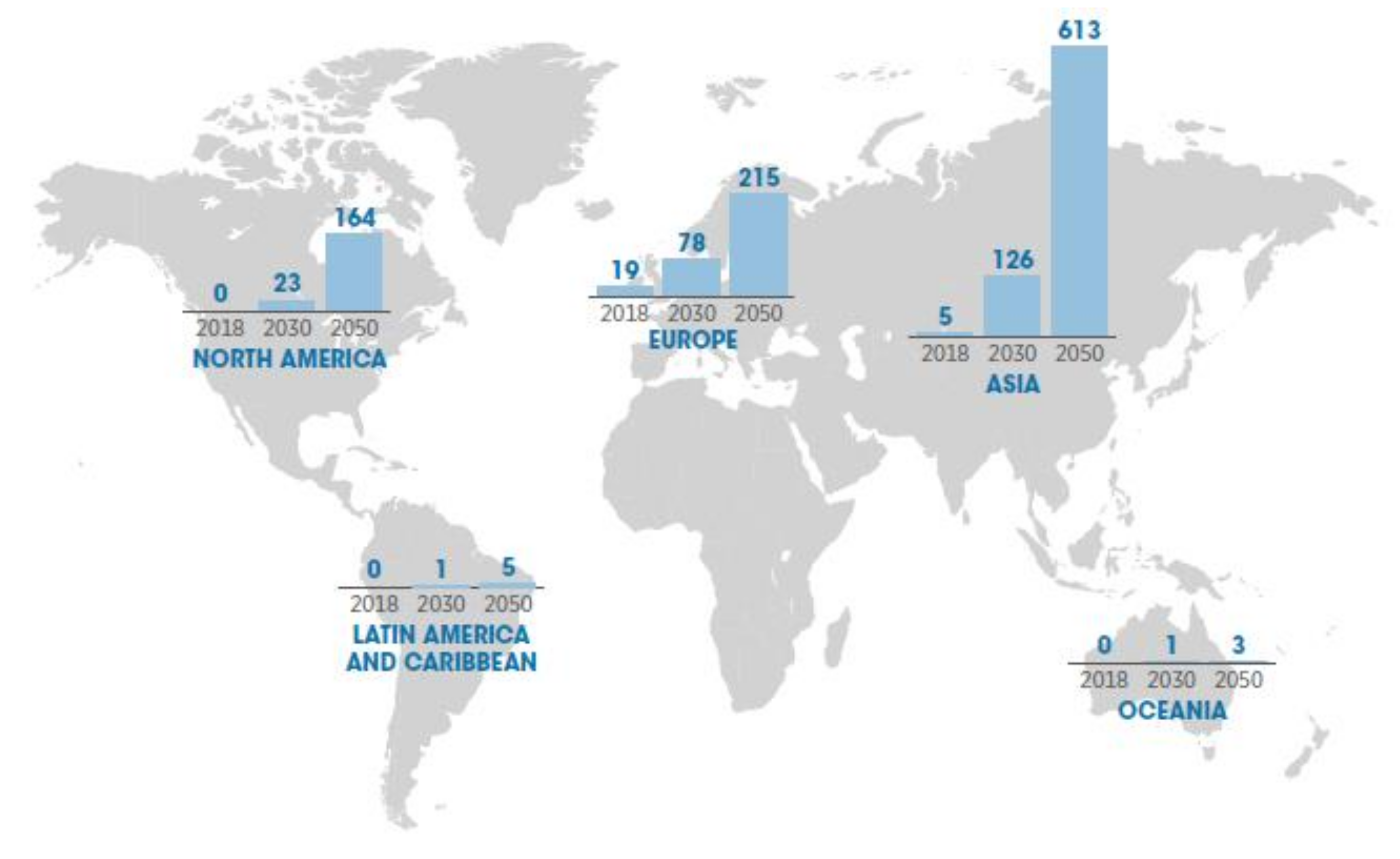
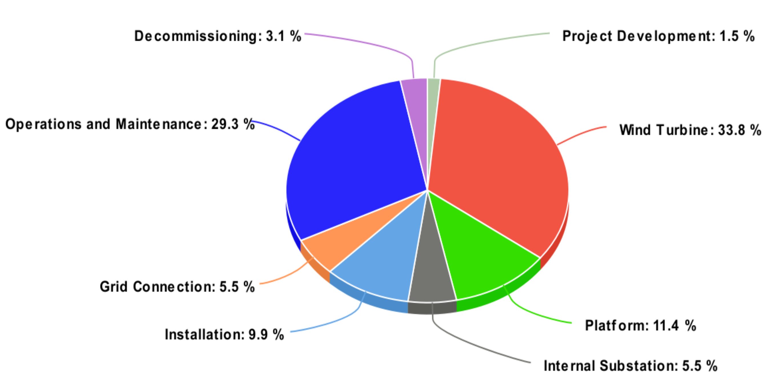
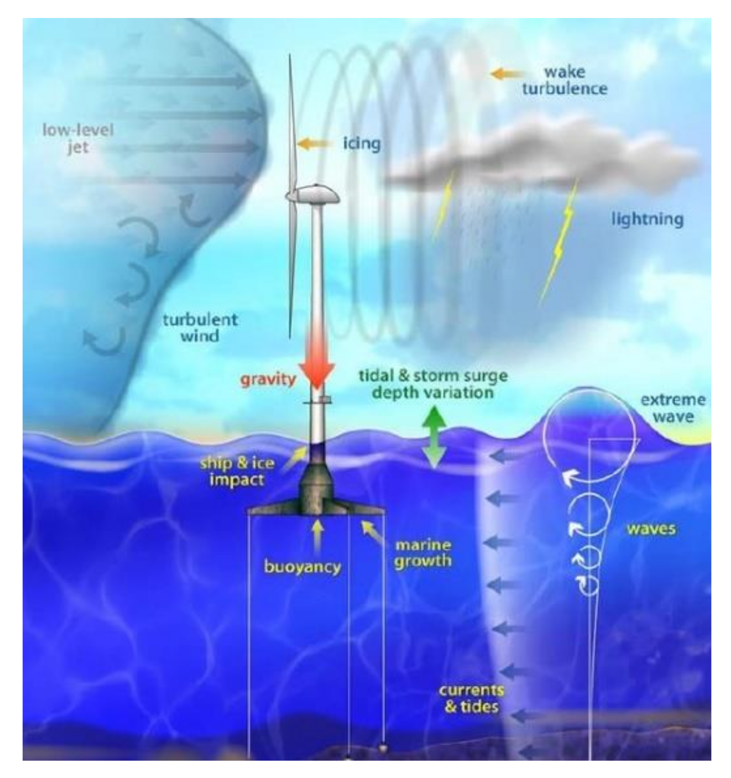
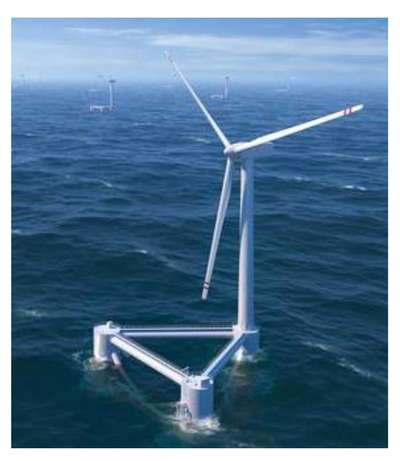
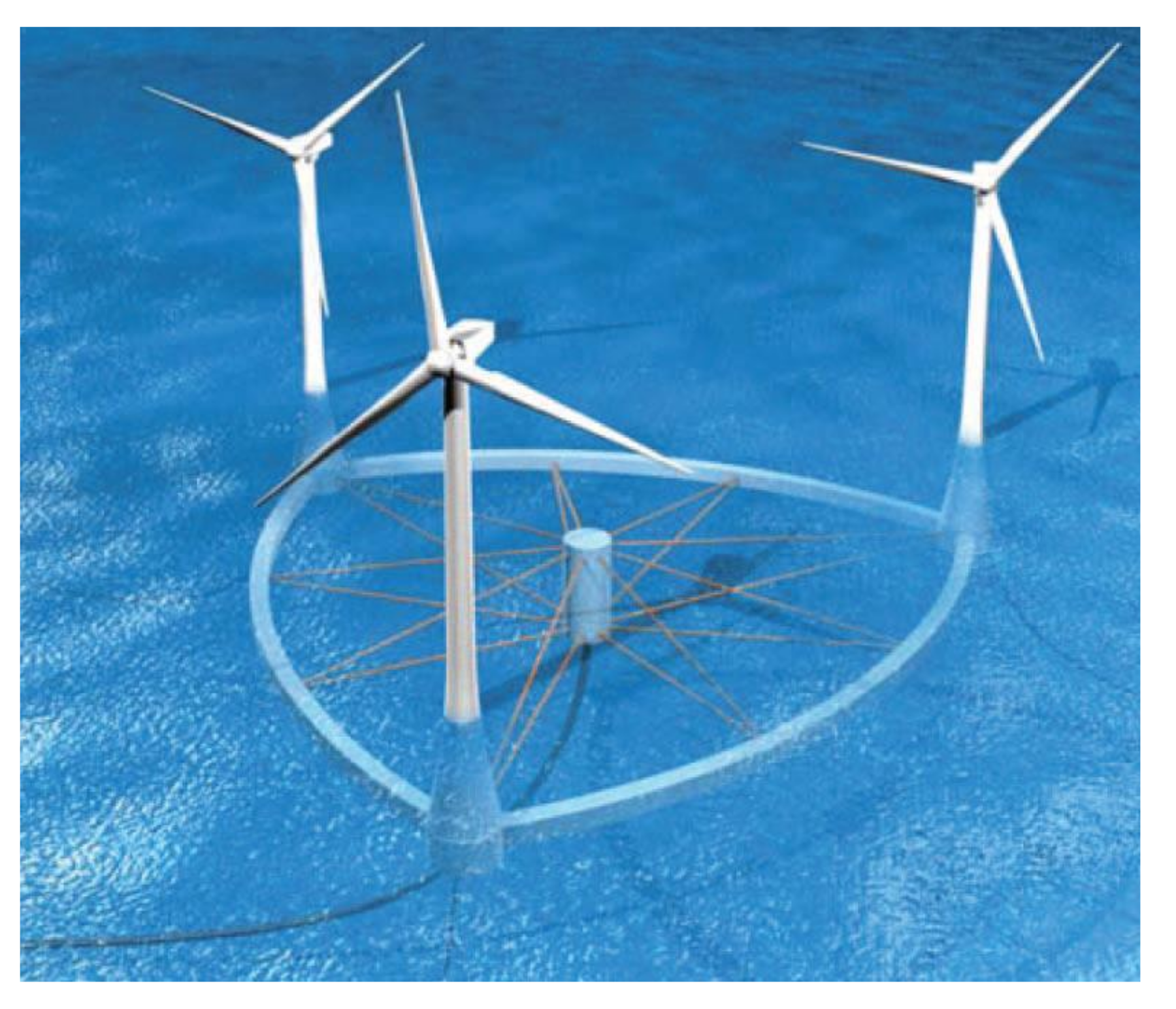
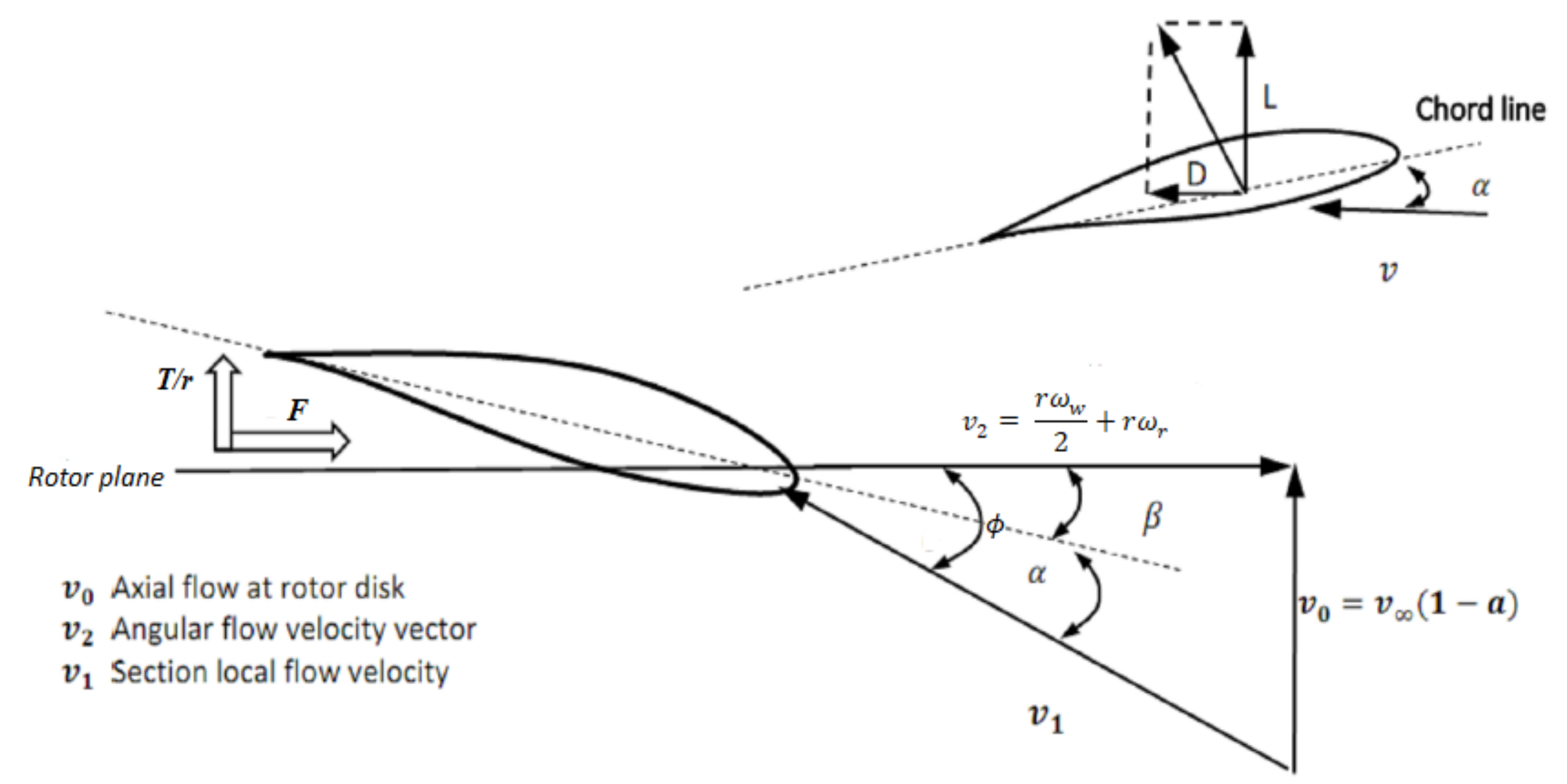
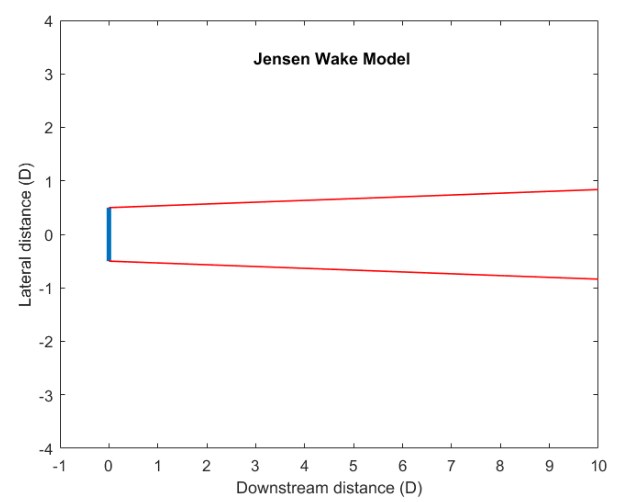
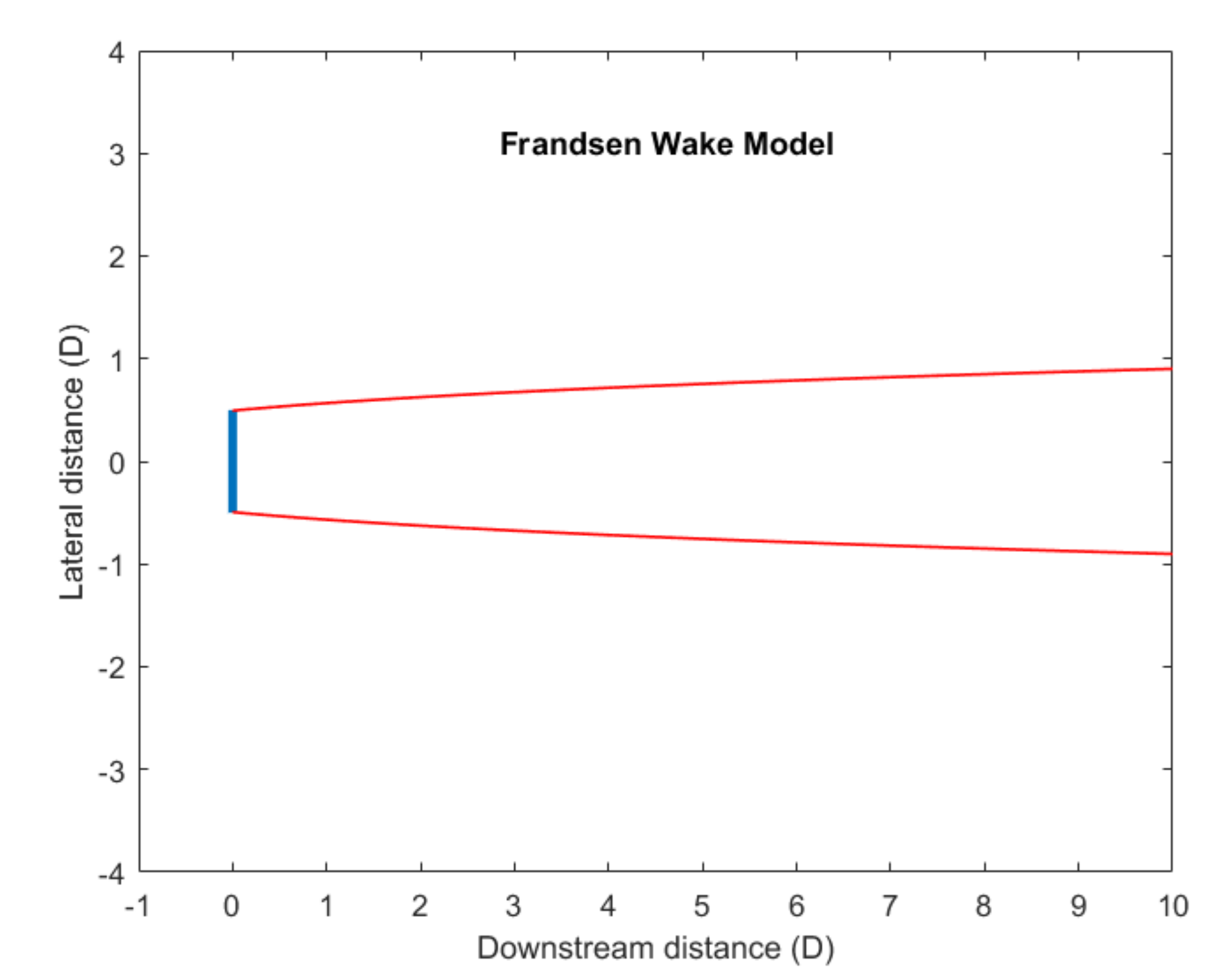
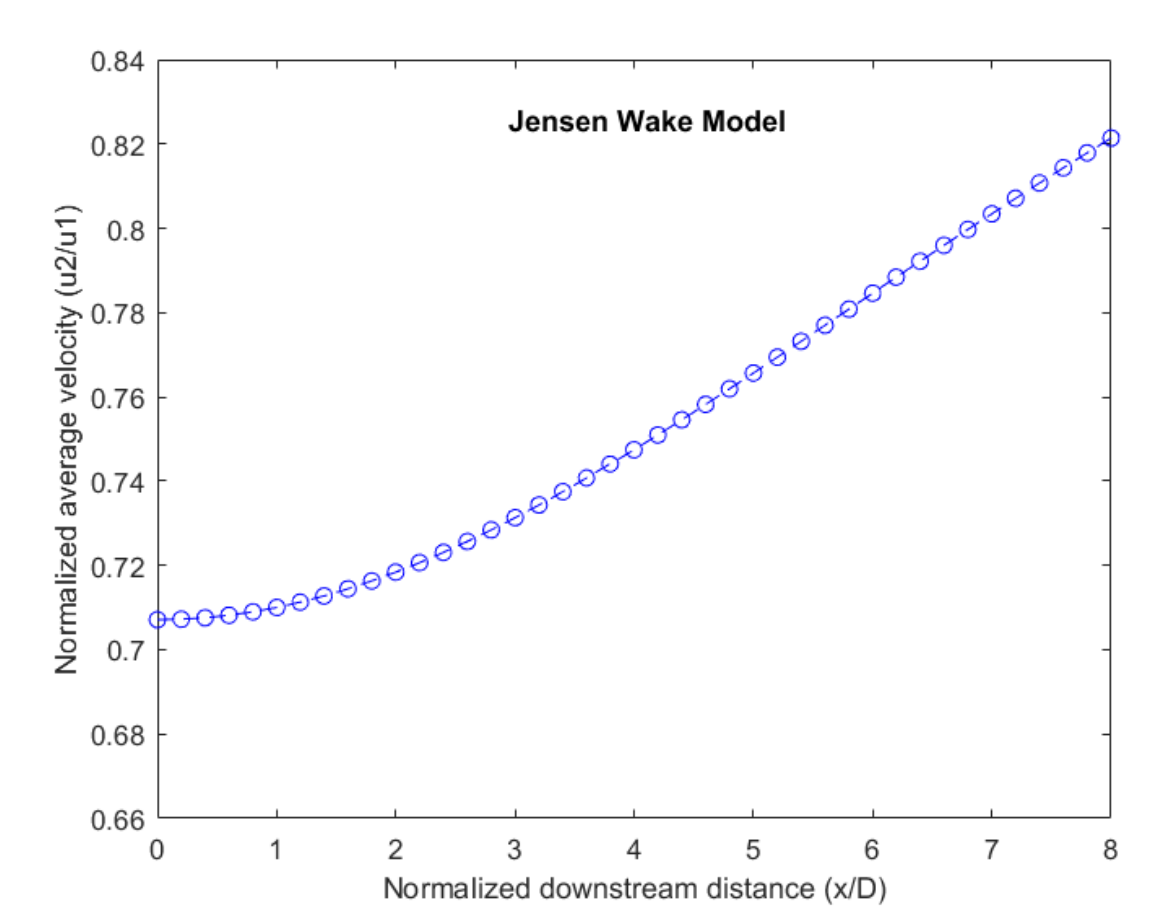
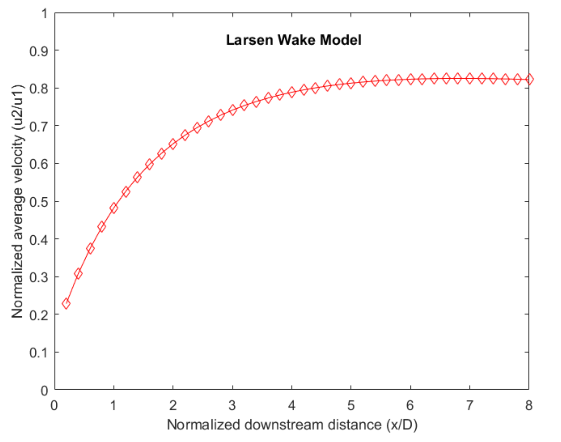
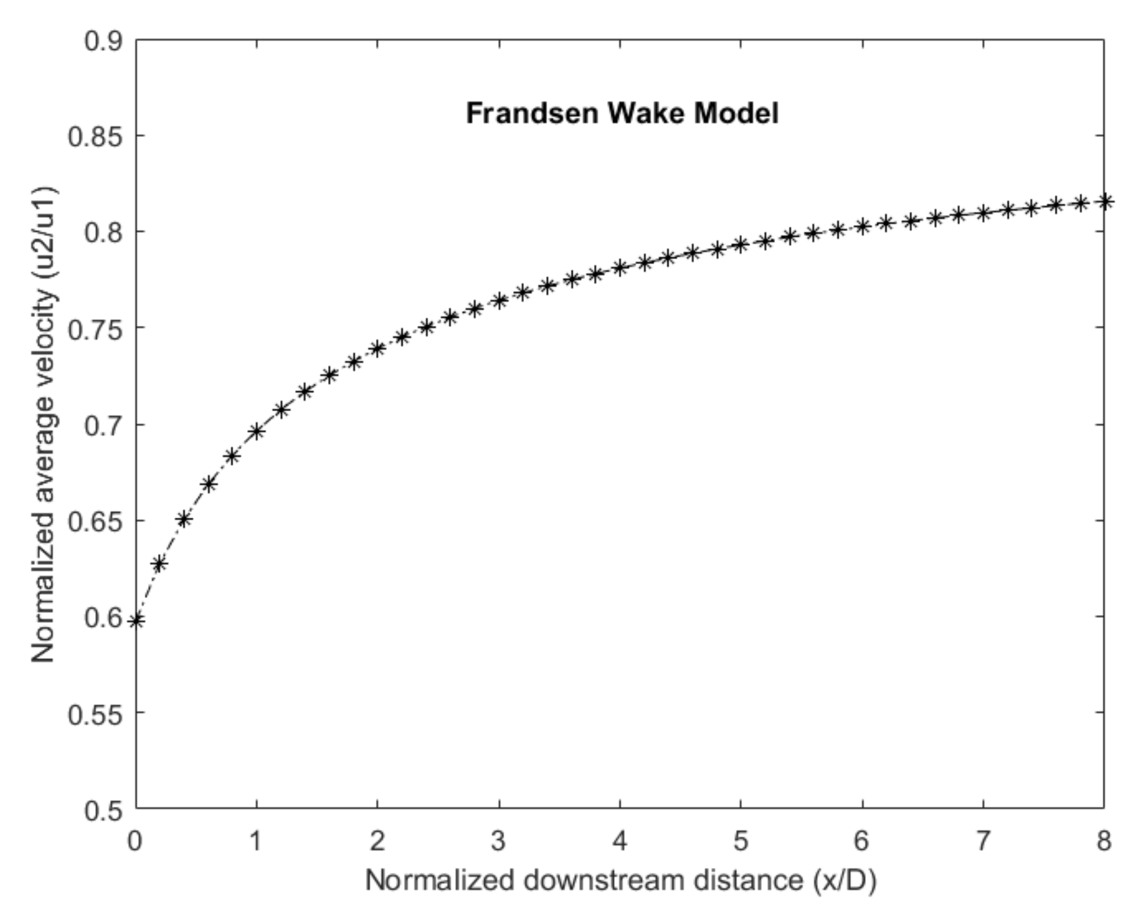
Table 1.
Comparison of different offshore floating platforms.
| Advantages | Disadvantages | |
|---|---|---|
| Semi-submersible platform |
|
|
| Barge platform |
|
|
| Spar buoy platform |
|
|
| TLP platform |
|
|
Table 2.
Assessment of primary floating platforms.
| Semi-Submersible | Tension Leg Platform | Spar-Buoy | |
|---|---|---|---|
| Turbine weight | 1 | 0 | −1 |
| Moorings | −1 | 1 | −1 |
| Anchors | 1 | −1 | 1 |
| Construction and installation | 1 | −1 | −1 |
| Operation and Maintenance | 1 | 1 | 0 |
| Wave sensitivity | −1 | 0 | 1 |
| Coupled motion | −1 | 1 | 0 |
| Natural periods | −1 | 1 | 0 |
| LCOE | 1 | −1 | 1 |
Table 3.
Comparison of single and multiple wind turbine floating platforms.
| Advantages | Disadvantages | |
|---|---|---|
| Single wind turbine floating platform |
|
|
| Multi-Wind-Turbine floating platform |
|
|
Publisher’s Note: MDPI stays neutral with regard to jurisdictional claims in published maps and institutional affiliations. |
© 2021 by the authors. Licensee MDPI, Basel, Switzerland. This article is an open access article distributed under the terms and conditions of the Creative Commons Attribution (CC BY) license (https://creativecommons.org/licenses/by/4.0/).
Share and Cite
MDPI and ACS Style
Bashetty, S.; Ozcelik, S. Review on Dynamics of Offshore Floating Wind Turbine Platforms. Energies 2021, 14, 6026. https://doi.org/10.3390/en14196026
AMA Style
Bashetty S, Ozcelik S. Review on Dynamics of Offshore Floating Wind Turbine Platforms. Energies. 2021; 14(19):6026. https://doi.org/10.3390/en14196026
Chicago/Turabian StyleBashetty, Srikanth, and Selahattin Ozcelik. 2021. "Review on Dynamics of Offshore Floating Wind Turbine Platforms" Energies 14, no. 19: 6026. https://doi.org/10.3390/en14196026
Note that from the first issue of 2016, this journal uses article numbers instead of page numbers. See further details here.